patent · US6087579
Method and apparatus for directing solar energy to solar energy collecting cells
11 July 2000
Page 1 — bibliographic record
United States Patent (19) 11 Patent Number: 6,087,579 Muskatevc (45) Date of Patent: Jul. 11, 2000 54 METHOD AND APPARATUS FOR 4,933,020 6/1990 Wenzel .................................... 136/246 DIRECTING SOLAR ENERGY TO SOLAR 5,009.243 4/1991 Barker ..... ... 136/246 ENERGY COLLECTING CELLS 5,344,497 9/1994 Fraas et al. ............................. 136/246 5,437,735 8/1995 Younan et al. ......................... 136/251 5,520,747 5/1996 Marks ..................................... 136/245 76 Inventor: Mark S. Muskatevc, 2006 N. 119 St., 2- 1 - 2
Wauwatosa, Wis. 53226 5,538,563 7/1996 Fink ....................................... 136/246
FOREIGN PATENT DOCUMENTS
21 Appl. No.: 09/035,451 59-231358 12/1984 Japan ................................. F24J 3/02 22 Filed: Mar.e 5,as 1998 2054826 2/1981 United Kingdom ............... F24J 3/02 O O Primary Examiner Bernard Codd
Related U.S. Application Data Attorney, Agent, or Firm Andrus, Sceales, Starke & 60 Provisional application No. 60/041.212, Mar. 26, 1997. Sawall 51) Int. Cl." ....................... H01L 31/048; H01L 31/052; 57 ABSTRACT
52 U.S. Cl. ........................... 136,251; 136/246; 136/248. A photovoltaic array includes a plurality of generally planar 58 Field of Search ..................................... 136/245, 246 cells, arranged in panels, a light collecting body having a 136/248,251 Solar energy collecting Surface adapted to be oriented for s receiving Solar energy in a nominal direction which defines 56) References Cited a nominal light Source direction. The panels are Spaced apart from each other in a direction perpendicular to the nominal
3,152.926 10/1964 Power ..................................... 12 on the body at an angle of less than 90° relative to the 3,419,434 12/1968 Colehower ....... ... 136/246 nominal light Source direction. The light collecting body is 3,627,585 12/1971 Dollert et al. ... ... 136/245 transmissive for redirecting light received on the light col 4,200,472 4/1980 Chappell et al. ... 136/246 lecting Surface onto the active Surfaces of the panels. 4,395,582 7/1983 Damsker .............. ... 136/248 4,410,757 10/1983 Stamminger et al. .................. 136/248 17 Claims, 8 Drawing Sheets
Page 2
Drawing sheet — no readable text.
Page 3
Drawing sheet — no readable text.
Page 4
Drawing sheet — no readable text.
Page 5
Drawing sheet — no readable text.
Page 6
Drawing sheet — no readable text.
Page 7
Drawing sheet — no readable text.
Page 8
Drawing sheet — no readable text.
Page 9
Drawing sheet — no readable text.
Page 10
METHOD AND APPARATUS FOR medium, and redirecting the Solar energy from the input DIRECTING SOLAR ENERGY TO SOLAR Surface through the optic medium and into the panels. ENERGY COLLECTING CELLS It is a general object of the invention to provide a new and improved photovoltaic array.
RELATED APPLICATION
Another object of the invention is to provide a photovol
This application relates to Provisional Application Ser. taic array which provides a greater energy output for a given No.: 60/041,212 filed Mar. 26, 1997. facial Surface area.
FIELD OF THE INVENTION
A further object of the present invention is to provide a photovoltaic array that can be used in applications having
This invention relates to photovoltaic cells and more limited Surface area.
particularly to a high efficiency photovoltaic cell. Yet another object of the present invention to provide for a photovoltaic array wherein Solar energy is collected and
BACKGROUND PRIOR ART redirected onto the Surface of Solar panels.
Solar energy cells are a Safe, non-polluting, inexhaustible 15 It is a further object of the present invention to provide a Source of energy. These generally take the form of a flat photovoltaic array wherein Solar energy is enhanced and panel collector array orientated generally perpendicularly to redirected onto Solar cells.
the Sun's rays. However, because of the relatively low power These and other features and advantages of the invention output of Such Systems, their use has been generally limited will become apparent upon review of the following detailed to Such remote applications as control Systems, Small elec description of embodiments of the invention, claims and tric motors and lighting in remote areas where conventional drawings.
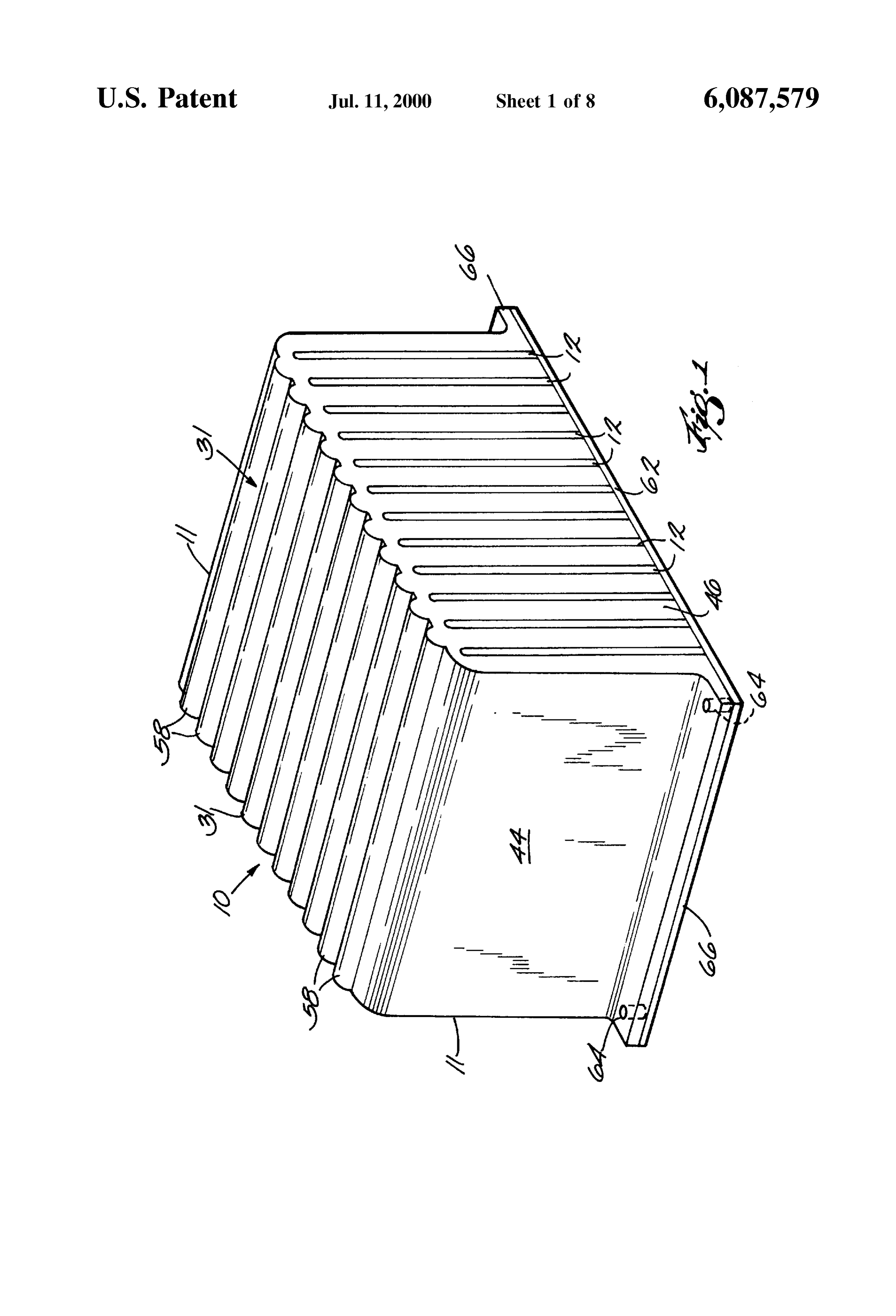
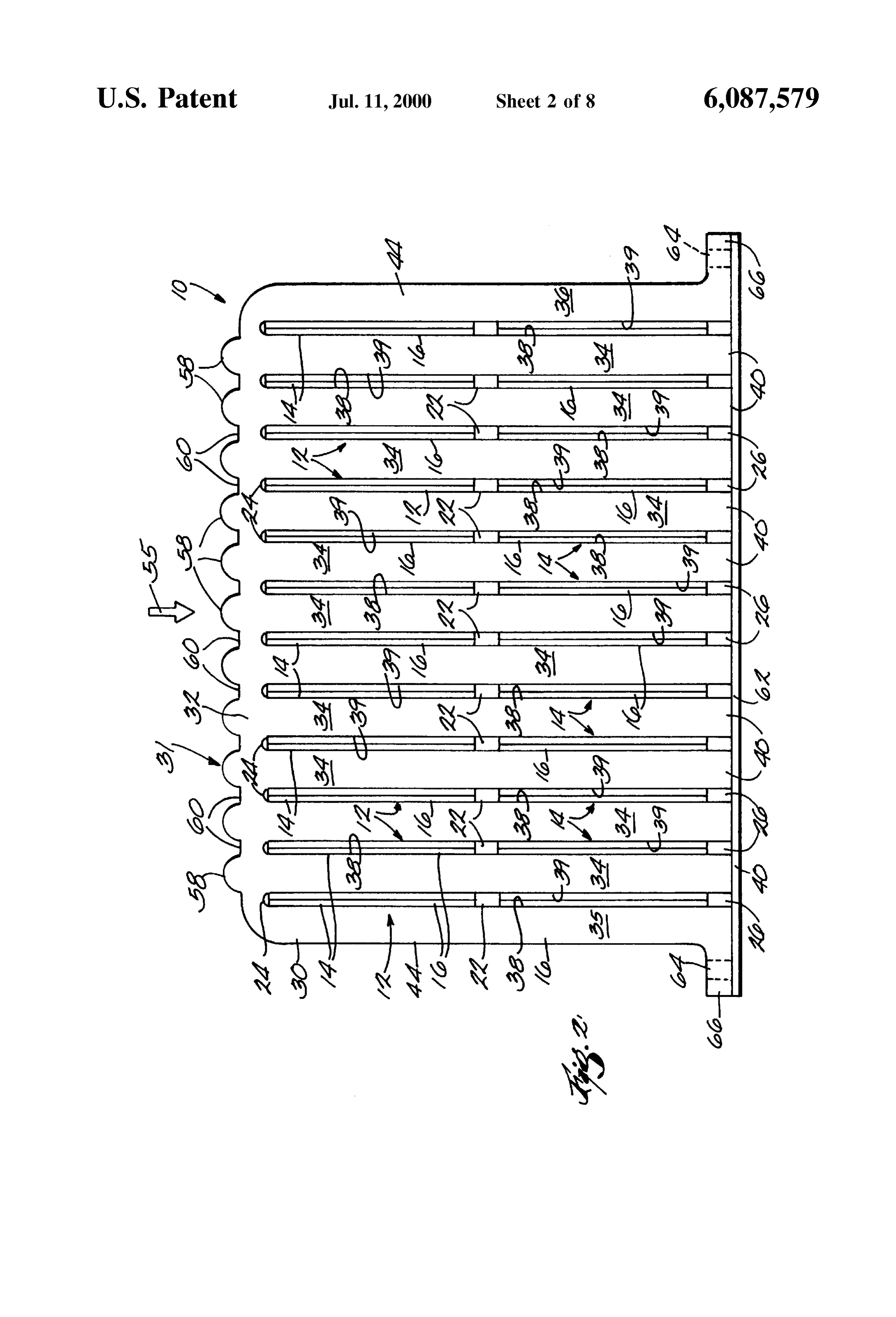
energy Sources are not readily available. Because of the limited output of conventional prior art Solar cell Systems, BRIEF DESCRIPTION OF THE DRAWINGS most efforts regarding their use involves attempts to reduce the power requirements of devices which rely on Solar 25 FIG. 1 is a perspective view of a solar module embodying energy and increasing the output of the cells by increasing the present invention;
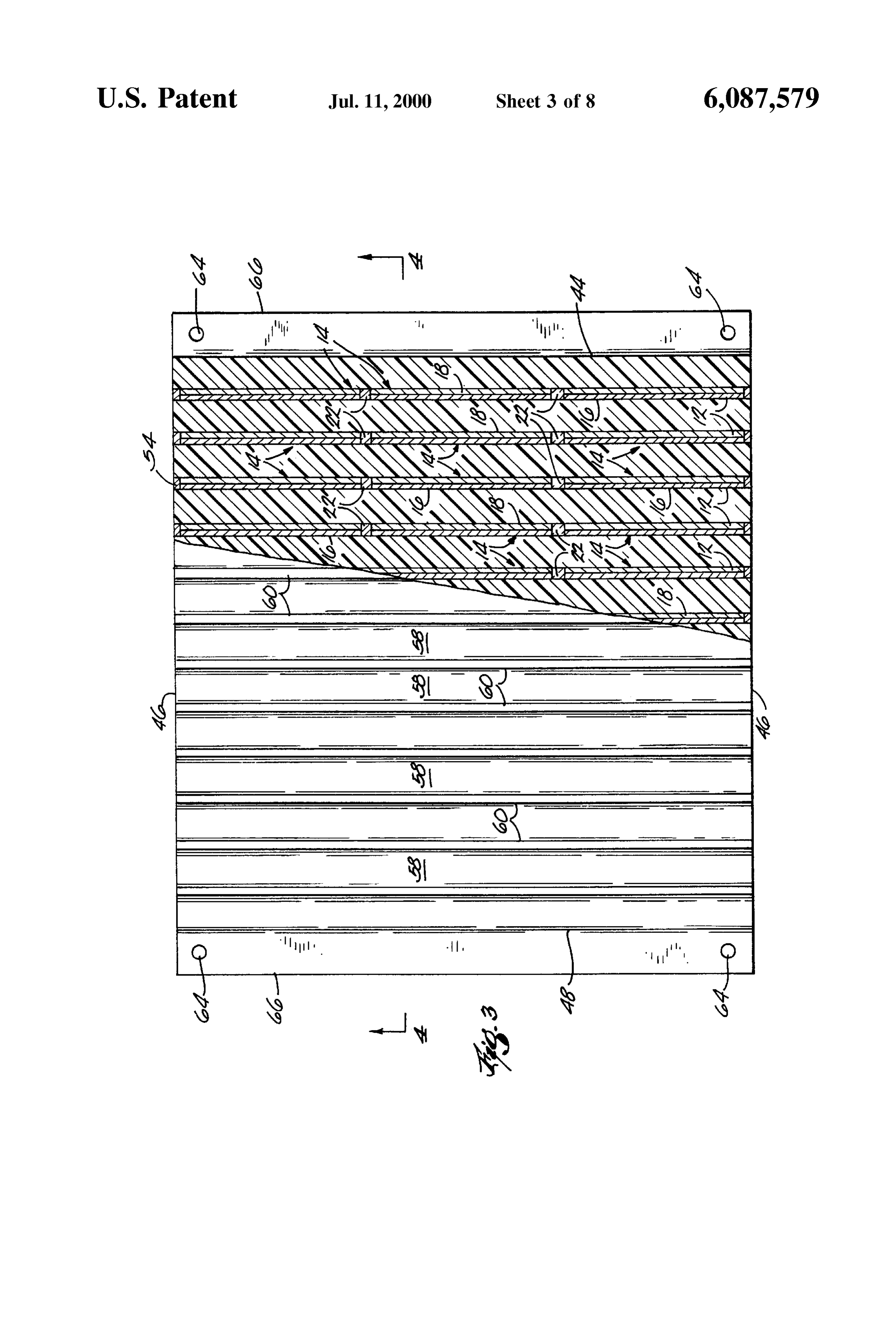
the quality of the materials used. However, in many Such FIG. 2 is a side view of the module of FIG. 1; applications, Space limitations often limit the number of FIG. 3 is a partial sectional top view of the module of FIG. panels that can be employed in a particular location. 1;
One attempt to render Solar cells more efficient includes FIG. 4 is a croSS Sectional view taken along line 4-4, of orienting a plurality of bi-facial Solar cells parallel to the FIG. 3;
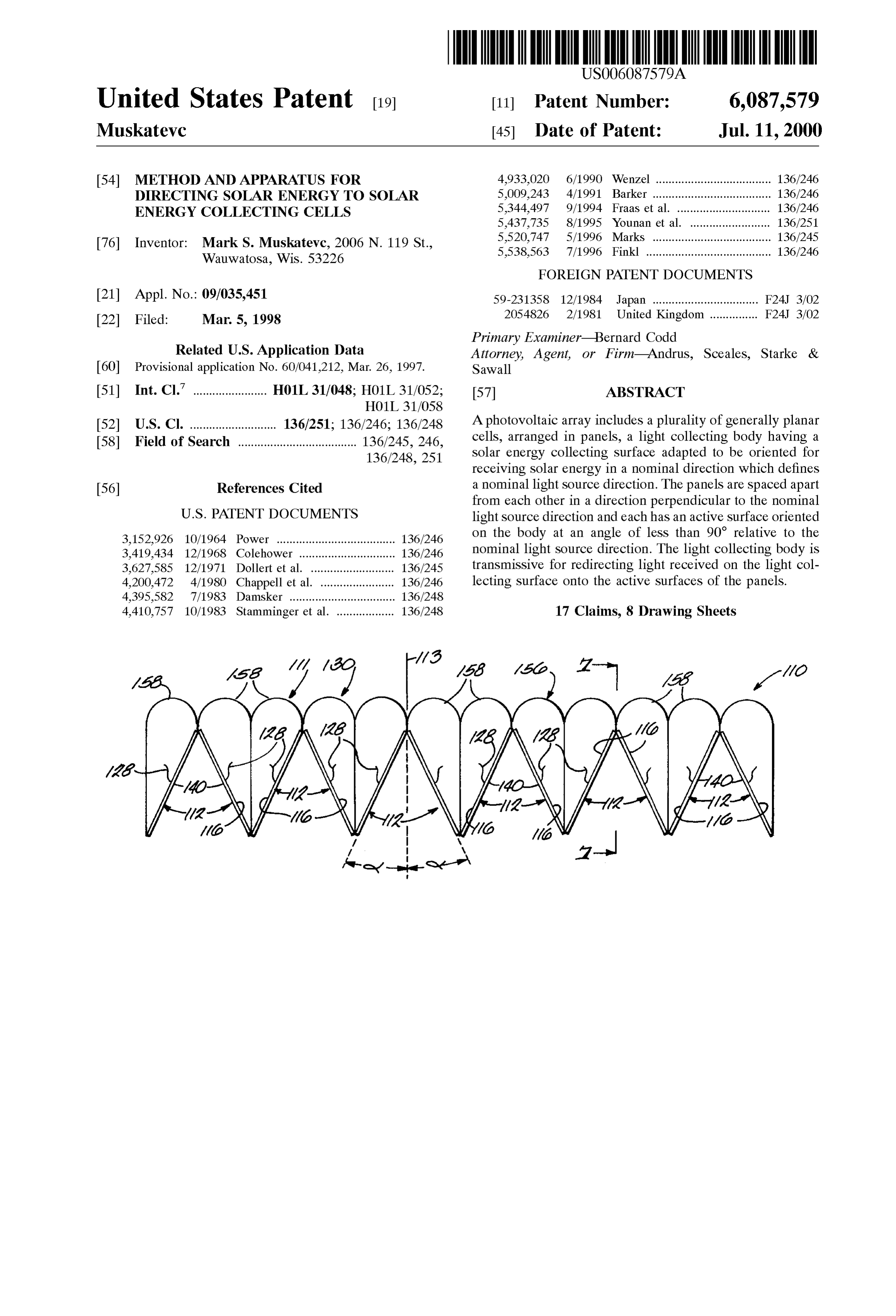
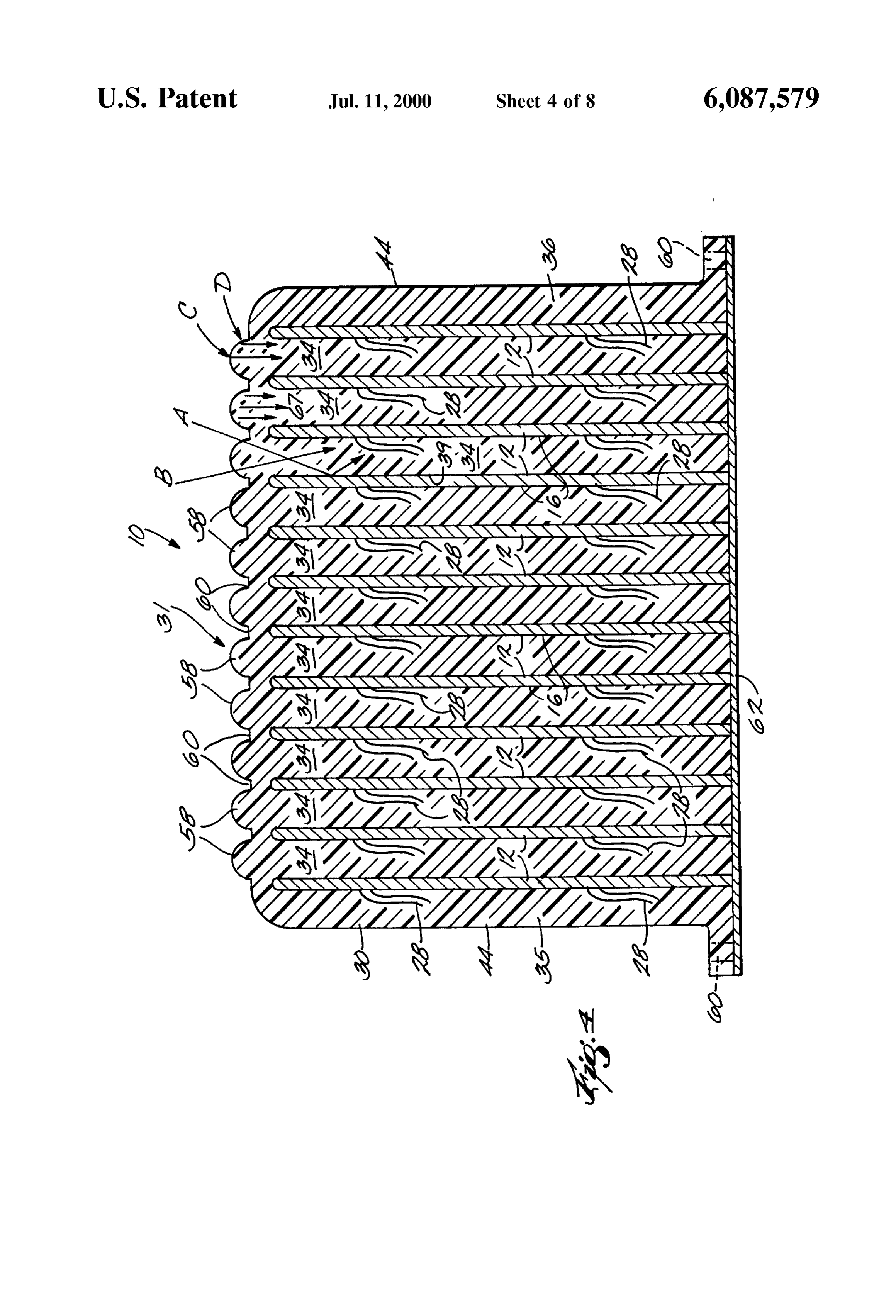
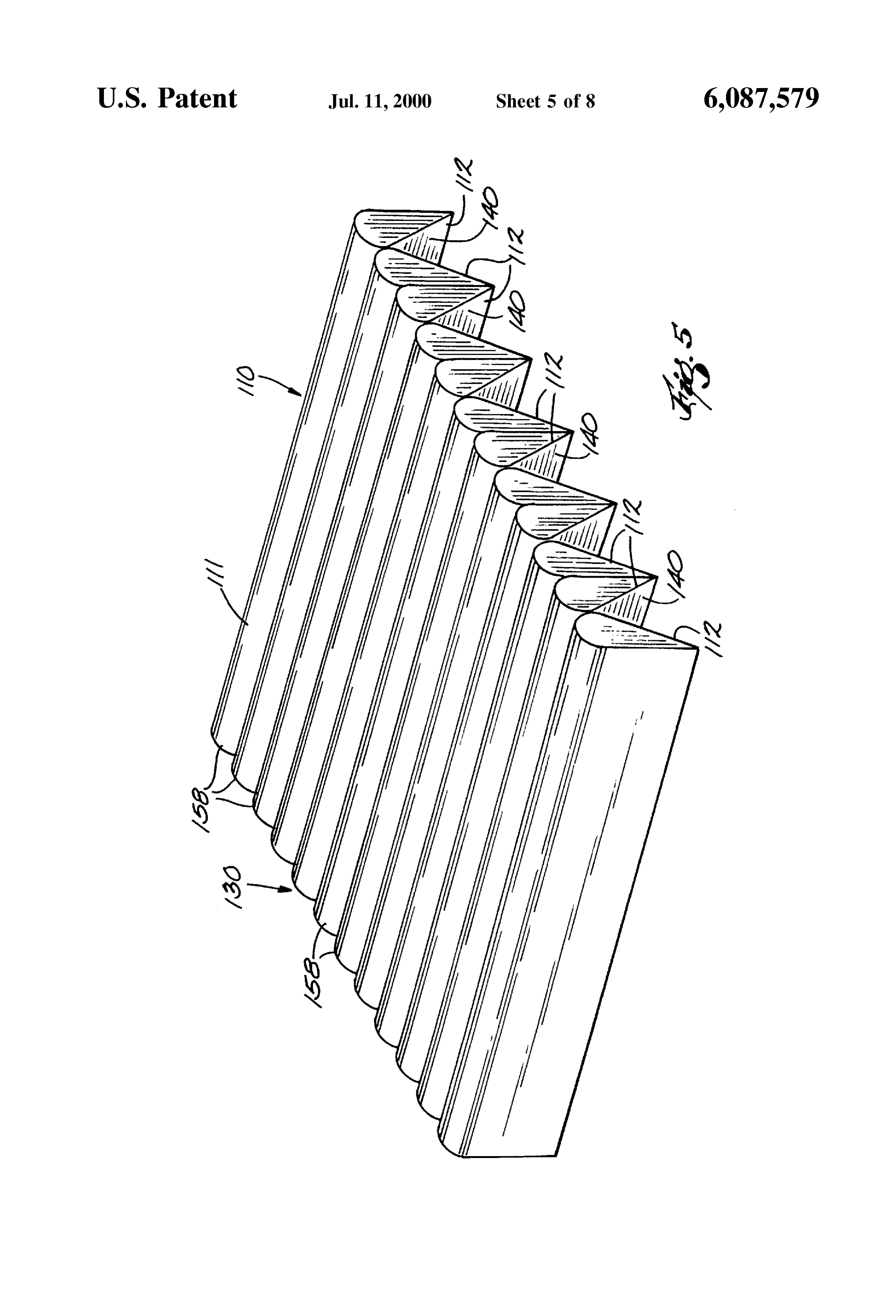
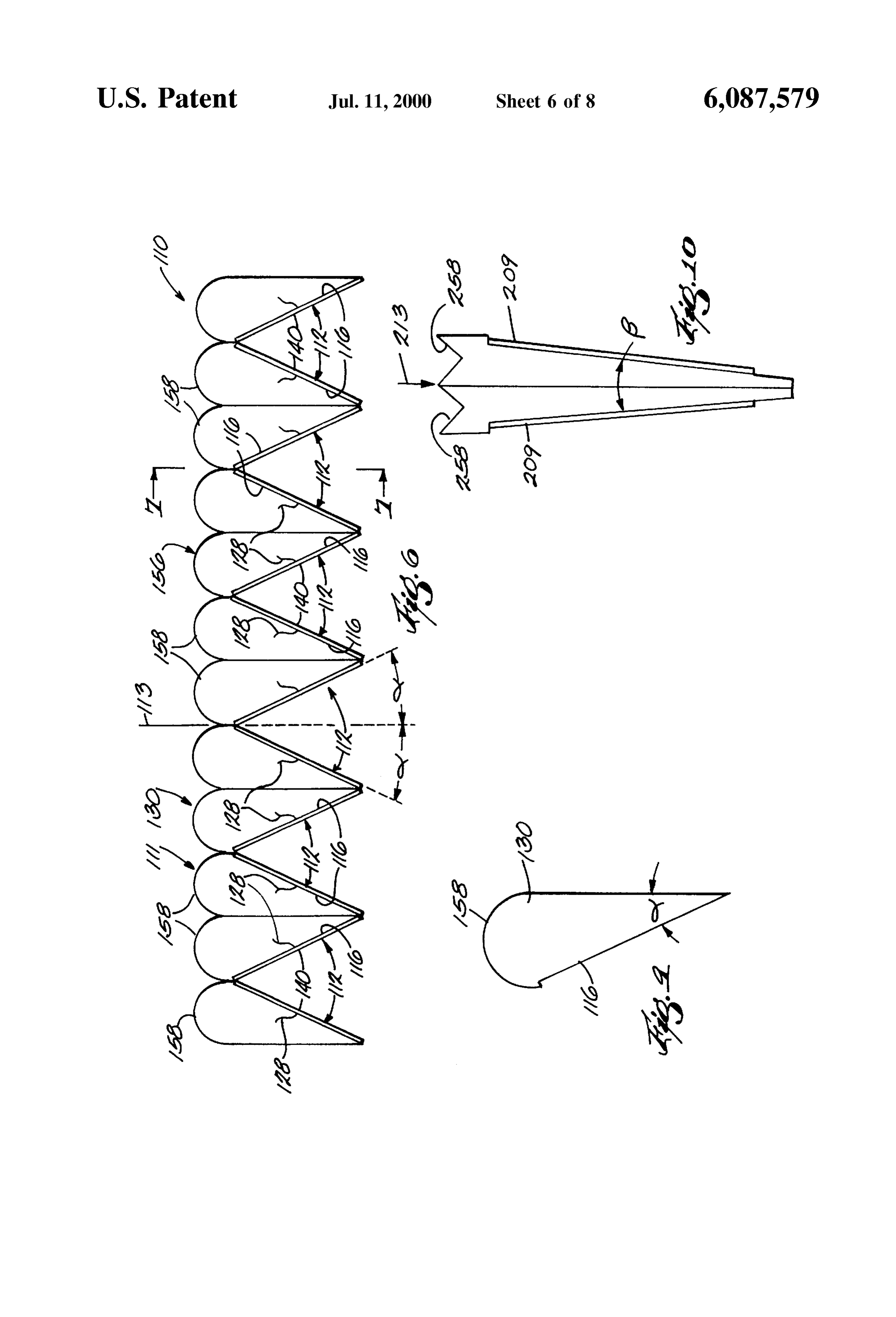
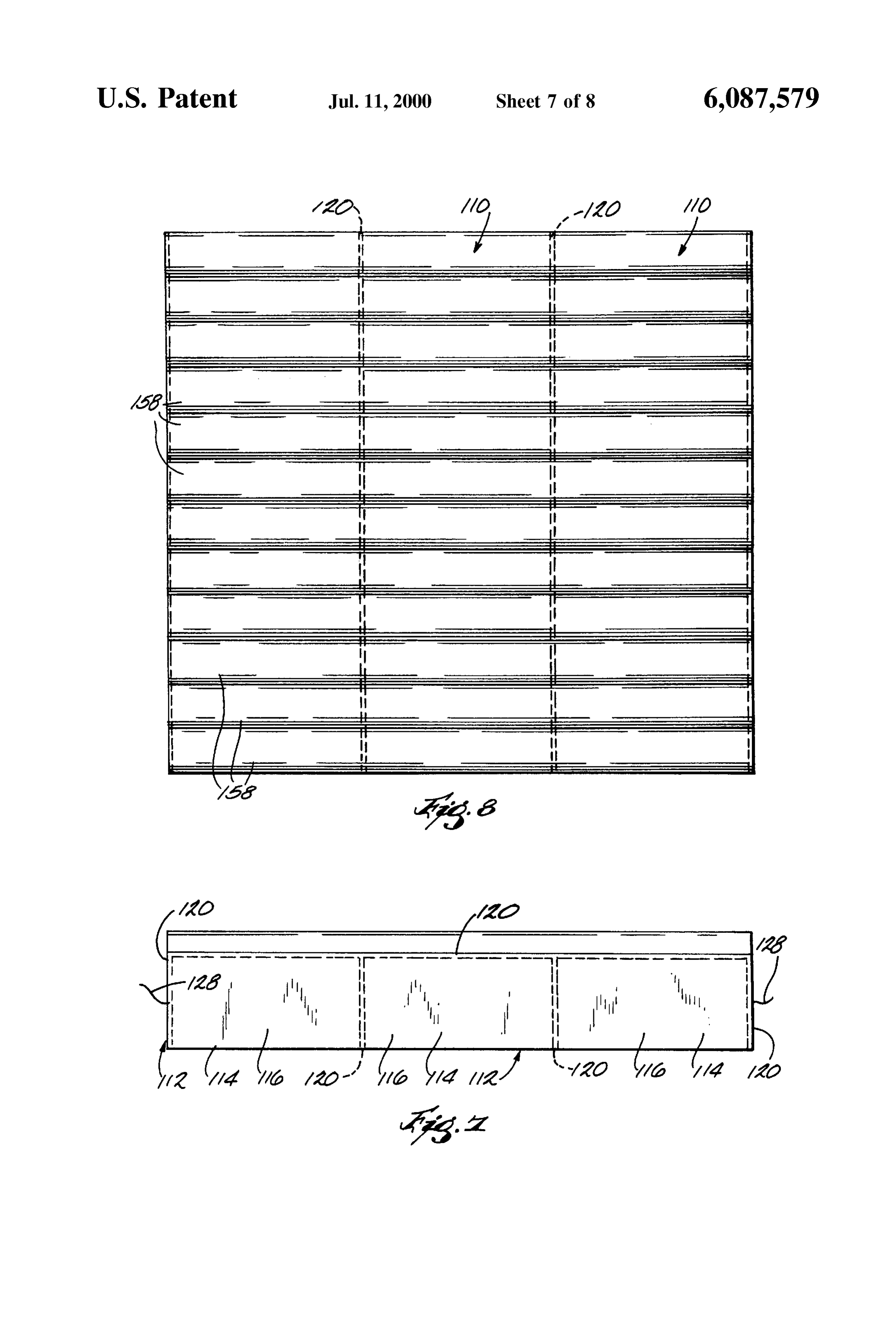
incident Solar rays and positioning reflectors therebetween FIG. 5 is a perspective view of a solar module incorpo for redirecting solar radiation onto the surfaces of the cells, rating the preferred embodiment of the invention; Such as that disclosed in U.S. Pat. No. 5,538,563. 35 FIG. 6 is an end view of the module shown in FIG. 5; SUMMARY OF THE INVENTION FIG. 7 is a view taken along lines 7-7 of FIG. 6; The invention provides photovoltaic cell array and Solar FIG. 8 is a top view of the module shown in FIG. 5; collector and concentrator. The Solar energy collector and FIG. 9 is an end view of a portion of the module shown concentrator is provided that can be used in applications that 40 in FIG. 5;
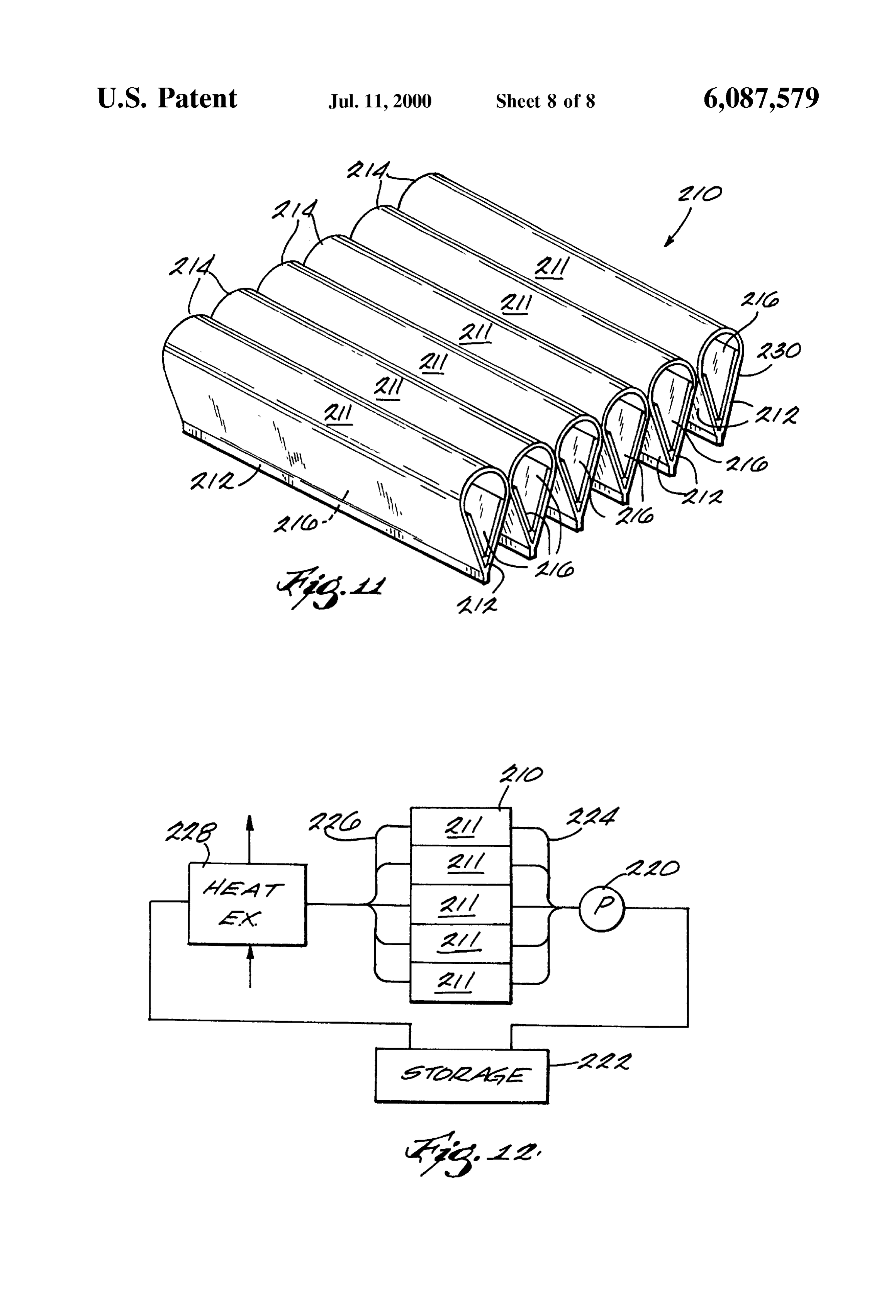
have limited Space for Solar panels. Additionally, the inven FIG. 10 is a further alternate embodiment of the inven tion provides a solar collector that allows for the efficient tion; and collection of Solar energy. FIGS. 11 and 12 show alternate embodiments of the One embodiment of the invention includes a Solar energy invention.
collector and a plurality of Solar cells each having a reactive 45 cell Surface. An optic medium is disposed between the Solar DETAILED DESCRIPTION OF THE cells and is adapted to receive and redirect Solar energy into EMBODIMENTS the reactive cell Surface. In general terms, the invention comprises a photovaltaic The invention includes a Solar energy collector and a array including a plurality of photovaltaic cells arranged in plurality of generally planar photovoltaic panels. Each of the 50 panels and a Solar energy or light collecting body having a panels has at least one reactive cell Surface. According to Solar energy or light collecting Surface adapted to be ori one embodiment of the invention, the panels are arranged ented for receiving Solar energy or light in a direction which generally parallel to one another and the nominal direction defines a nominal Solar energy direction. The panels are of the Solar energy. According to another embodiment of the arranged in an array which extends in a direction perpen invention, the panels are arranged at an acute angle relative 55 dicular to the nominal Solar energy direction and the panels to the nominal direction of the Solar energy. An optic are oriented on the light collecting body at an angle of leSS medium envelopes and is disposed between the panels. The than 90 relative to the nominal Solar energy direction. In the optic medium is adapted to concentrate and direct Solar embodiment shown in FIGS. 1-4, the panels are generally energy into the panels. Partially and fully reflective Surfaces parallel to the nominal Solar energy direction or, in other on the collector concentrate and redirect the light onto the 60 words, at an angle of 0. In the embodiment shown in FIGS. photovoltaic panels. 5-9, the panels are oriented at an acute angle relative to the The invention also includes a method for generating light source direction and in the embodiment of FIG. 10, the electrical energy from Solar energy and including the Steps panels are arranged at an angle between the embodiment of of providing a plurality of generally planar Solar panels FIGS. 1-4 and the embodiment of FIGS. 5–9. The light arranged generally parallel to one another and an optic 65 collecting body is characterized by an ability to refract and medium disposed in a Surrounding relation to the panels, redirect the Solar energy received at the Solar energy col receiving Solar energy in an input Surface of the optic lecting Surface onto the active Surface of the panels.
Page 11
FIGS. 1-4 show a first embodiment of the invention to A Solar energy collecting Surface 31 defines the upper comprise a Solar module 10 including a Solar energy col margin of the Web 32 and includes a plurality of Solar energy lector 11 and a plurality of photovoltaic panels 12 arranged collecting Sub-Surfaces 58 which are arcuate in transverse in a generally parallel relation to each other and to the croSS Section and extend in the first direction and parallel to nominal direction of the Solar energy. It would be appreci the panels 12. The sub-surfaces 58 are disposed in the gap ated that as a result of the earth's rotation, the angle of between the upper edges of the panels 12 and there is a flat incidence of the Solar energy will vary with the time of day area 60 between each of the Sub-Surfaces 58 and located and the elevation of the Sun relative to the horizon. above the upper edges of the panels 12 and are generally Accordingly, the term nominal Solar energy direction as used perpendicular to the nominal Solar energy direction 55. herein means an average angle of incidence of the Solar 1O The side Surfaces 46, end Surfaces 44, the lower Surface energy or light. Also, for purposes of discussion, it is 40, the upper edge 58 of the panels 12 and fin side surfaces assumed that the Solar module 10 of FIGS. 1-4 and 110 of 39 are all preferably treated Such as by roughening So as to FIGS. 5-9 are oriented so that they are symmetrical relative diffuse the Solar energy. Alternatively they may be coated to a plane containing the average angle of incidence. with a partially or substantially totally reflective film made Panels 12 may comprise one or more individual Solar cells 15 up of reflective material. AS used herein, "reflective mate 14 depending upon the Size of the module and the geom etries of the System and each cell has at least one active cell rial” includes any material that can be used to coat the Surface 16 for collecting energy. A Suitable Solar cell 14 Surfaces of the optic material to form a Substantially light which may be used in the embodiments of the invention is reflective surface.
reflective Suitable reflective material may include:
colored paints, Such as white gloSS, glass bead
Kyocera type PSC100H. Such cells may typically have maximum output of about 0.47 volts and 2.87 amps and a other Silver, glass bead chrome, mirrors, polished metals, or any maximum power output of about 1.35 watts. In the embodi reflective material known in the art. The reflective ment illustrated in FIGS. 1-4, there are 3 cells arranged end material can be glued, vacuum Sealed, Silk Screened, or to end in two rows which are electrically connected in Series. applied between two pieces of clear plastic film and lami The active surfaces 16 of the cells 14 in each panel 12 are nated onto the Surface of the medium to form the reflective oriented in the same direction. The cells 14 in each row are 25 film. It is preferable that reflective colored paints, Such as Separated by Spacers 22 and Spacers 24 and 26 are disposed white gloSS, glass bead Silver, or glass bead chrome, be used at the upper and lower edges of the rows of cells. Preferably, and Silk Screened onto the Surfaces of the optic medium to all of the spacers are colored white so that they do not absorb form the reflective film. The reflective film can be applied light energy. Leads 28 are connected to each of the panels 12 during or after the molding or forming of the optical medium for electrically connecting the cells to the load or System 30.
being energized. It will be appreciated that while a specific The fin side Surfaces 38 which abuts the active Surface of number of cells are illustrated in the embodiment of FIGS. the adjacent panel 12 and the convex sub-surfaces 58 of the 1-4, any number may be employed depending upon the size Solar energy collecting Surface 56 are also treated So as to and geometries of the System and the power requirements. diffuse the Solar energy. Alternatively they may be coated The module 10 also includes an optic medium 30 com 35 with a film which is partially reflective and partially con posed of an optic material that is disposed between the active ductive of Solar energy. The partially conductive film may Surfaces of the panels. AS used herein, optic material means include any material that can be applied to the Surfaces of the Substantially optically transparent material that is optic material and which allows most of the Solar energy machineable, moldable or shapeable into Structures in accor travelling in one direction to pass, and which also reflects dance with the invention. It is preferable that the optic 40 most of the Solar energy travelling in the opposite direction. material be plastic, glass or Silicon fibre but other materials Generally, the partially reflective film can be made up of the are also usable. One material found to be acceptable is a cast same reflective material as the totally reflective film, but the acrylic Supplied by Athoaas, model Plexiglass G. In the medium 30 by any suitable fastening device which extends embodiments of the invention, this material is molded into through openings 64 in flanges 66. Base plate 62 acts to hold the indicated shapes. 45 the Solar panels 12 in place within the medium 30. The The optical medium 30 includes a Solar energy or light flanges 66 may be omitted and the plate through openings in collecting Surface 31 positioned to receive Solar energy and the module So that spacing between modules can be mini defining the upper margin of a web 32. A plurality of fins 34 mized. The entire module 10 can be enclosed in a weather extend downwardly in a parallel relation from the web 32 tight housing (not shown), the design of which will prevent and fill the Spaces between the panels 12. There is also a pair 50 interference with the absorbing of Solar energy. The design of exterior fins 35 and 36 extending downwardly from the of the enclosure will be determined by the application for web 32 on each end of the module 10. A first Surface 38 of which the Solar module 10 will be used. each of the interior fins 34 and end fin 35 contacts the front In operation, the module 10 is placed in a position Such or active Surface 16 of the adjacent panel 12 and a Second that the input Surface 31 is exposed to Solar radiation and Surface 39 of each interior fin 34 and the other end fin 36 55 preferably is oriented So that Surface 31 is generally per contacts the rear or inactive Surface. The outer Surfaces of pendicular to the nominal energy Source direction. Direct fins 35 and 36 define end Surfaces 44, the lower ends and and ambient Solar radiation enters the module through the sides of the fins define a lower Surface 40 and side Surfaces Solar energy collecting Surface 31 including the flat areas 60 46, respectively. and the one-way reflective coated Surfaces 58. The Solar The configuration of the fins 34 positions the panels 60 energy collecting Surface 31, along with the other reflective parallel to the nominal Solar energy direction 55 which in Surfaces in the medium 30 act to direct the Solar energy to FIG. 2 is shown to be perpendicular to the Solar energy the solar panels 12. For example, referring to FIG. 4, if solar receiving Surface 32. The panels 12 also extending in a first energy A enters the medium 30 at flat area 60 from one side, direction generally perpendicular to the nominal Solar the Solar energy A is refracted downwardly and onto the energy direction. In addition, the panels 12 are Spaced apart 65 reflective Surface 39 for redirection onto the active Surface along a horizontal line which is also perpendicular to the 16 of the panel 12. Solar energy Bentering at an angle from nominal Solar energy direction and also the first direction. the other side is refracted downwardly between the panels.
Page 12
S 6
Solar energy C and D entering the convex surfaces 58, is are connected to each of the panels 112 for proper electrical directed downwardly into one of the fins 34. Moreover the connection in accordance with the use of the Solar module Surfaces 58 are configured Such that it reflects Solar energy 110.
67 downwardly in a generally parallel relation. The module 110 also includes an optic medium 130 which Once the Solar energy enters the fins 34, it may reflect off 5 at least fills the Spaces between the active cell Surfaces. All of a totally reflective side surface 39 into one of the partially of the surface of the medium 130 are clear for transmitting reflective side surfaces 38, or it may flow directly to one of Solar energy. The medium 130 may be composed of the same the partially reflective side surfaces 38. The partially reflec material as discussed with respect to the embodiments of tive side Surfaces 38 act as a Solar energy output Surface Such FIGS. 1-4. The back faces 140 each of the panels 112 may that the majority of the Solar energy is directed in a generally be covered by an opaque material and the Space between the perpendicular relation onto the reactive Surface 16 of the Surfaces 140 may be open for purposes of economy. Solar panels 12. The remainder of the energy is reflected A Solar energy input Surface 156 is provided at the upper back towards the reflective side surface 38, which again end of the optic medium 130 and is subdivided into a reflects the remaining energy towards an output Surface 38. plurality of convex sub-surfaces 158 each of which extends AS the Solar energy is reflected down the fins 34, Substan 15 in the first direction, which is also the direction in which the tially all of the Solar energy that enters the fins 34 is directed panels 112 extend. Each of the sub-surfaces 158 may be through the output surface 38 and is absorbed by the solar generally parabolic in cross-section and each has an end cells 14. adjacent to the upper edge of each panel and a Second edge Both ambient and direct Solar energy enters the collecting in a plane which bisects the angle formed by the lower edges Surface 31, and through the reflective action of the Surfaces of the adjacent panels and which is parallel to the energy in directing the energy into the fins, often the reflected Solar Source direction 113. This provides one of the sub-surfaces energy combines with and enhances other Solar energy 158 above each of the panels 112.
within the optic medium 30. This results in the amplification In operation, the module 110 is positioned such that the of the Solar energy as it passes through the optic medium30. 25 input surface 156 is exposed to Solar radiation. Direct and AS the Solar energy is collected by the Solar panels 12, the ambient solar radiation enters the module 110 through the Solar energy is converted into electrical energy. The electri Solar energy collecting surface 156. The sub-surfaces 158 cal energy is then transferred from the Solar panels 12, and tend to refract the Solar energy downwardly onto the active collected for use. In Some applications, the energy is Stored surfaces 116 of the Solar panels 112. It has been found that in an electrical energy storage device, Such as a battery (not the energy output from the configuration shown in FIGS. shown). In other applications, the energy is put to immediate 5-9 provides about twice the power output for a given input Sc. Surface area than a conventional Solar panel array having the In other embodiments of the invention, bifacial Solar cells Same input area. Facial Surface area as used herein means the could be used, or Solar cells could be placed back to back area defined by the length and width of the module 110 as Such that both sides of the panel contain reactive cell 35 viewed in FIG. 8.
Surfaces. In Such an embodiment, the Surfaces 38 and 39 of The angle C. between each panel and the nominal direction the fins 34 would all be semi-reflective and act as output of the Solar energy 113 is determined by the number of Solar Surfaces. Additionally, in other embodiments, multiple mod panels 112 that are desired to be positioned within the ules can be interconnected to form an array of Solar energy module 110 having a given facial Surface area. By decreas collecting devices. 40 ing the angle C, the number of Solar panels 112 increase for FIGS. 5-9 show a solar module 110 embodying one a given facial area. Since the number of panels 112 not only preferred embodiment of the invention. The Solar module increase the output but also the cost, there is a power 110 includes a solar energy collector 111 and a plurality of expense trade off.
Solar panels 112 all arranged at the same acute angle a FIG. 10 shows an alternate embodiment of the invention relative to the nominal direction of Solar energy 113. As 45 wherein the Solar panels 209 are positioned at an angle B shown in FIG. 7, the solar panels 112 each includes at least relative to the nominal Solar energy direction 213. The angle one solar cell 114 having at least one active cell Surface 116 B is Smaller than the angle C. and permits the use of a larger for Solar energy. One suitable Solar cell 114 which may be number of Solar panels 209. The size of the angle between used is a Kyrocera type PSC100H. Such cells may typically Solar panels is inversley related to the number of panels. have a maximum output of about 0.47 volts and 2.87 amps 50 Also, the Sub-Surfaces 258 in the embodiment of FIG. 10, and a maximum power output of about 1.35 Watts. consists of V-shaped grooves for receiving and refracting In the embodiment FIGS. 5-9, each panel consists of a Solar energy.
plurality of cells 114 arranged end to end and electrically FIG. 11 is a perspective view of a preferred embodiment connected in Series, with Spacers 120 disposed between the of the invention and is similar to the embodiment of FIGS. cells and along the upper, lower and outside edges. 55 5-9 except that the Solar energy collector 210 consists of a The panels 112 are oriented Such that adjacent panels lie plurality of hollow bodies 211 joined in a side-by-side in interSecting planes and alternate panels are oriented in relation and each having a pair of Sidewalls 212 formed at parallel planes So that the angle between each adjacent pair an angle of 2C. relative to each other. The side of the bodies of panels forms an angle of C. With the nominal Solar 211 opposite the junction of the Sidewalls 212 comprises an direction for an angle of 2 C. relative to an adjacent panel. 60 arcuate Solar collector 214 which is generally parabolic in Also, the panels 112 extend in a first direction perpendicular transverse croSS Section and is composed of the Same optic to the nominal Solar energy direction 113 and are arranged material which is transparent to Solar energy as discussed in a row extending in a direction which is perpendicular both with respect to the embodiments of FIGS. 1-4. A Solar panel to the direction in which the panels extend and the nominal 216, such as that discussed with respect to FIGS. 5-9, is Solar energy direction 113. In addition, the active Surfaces 65 positioned on the inner surface of each of the side walls 212 116 of the panels 112 are on the side of the panel which faces and with their active Surfaces facing inwardly. The ends of upwardly and inwardly. As seen in FIGS. 6 and 7, leads 128 the bodies 211 may be closed and the hollow interior may be
Page 13
filled with a clear liquid, Such as water, or an inert gas, Such 5. The photovoltaic array of claim 1 wherein the active as, argon or nitrogen. Solar energy impinging on the col Surface of each Solar cell is positioned in contact with one of lectors 211 is redirected downwardly onto the active Sur the sidewalls of the light collecting body. faces of panels 216 for conversion into electrical energy. 6. The photovoltaic array of claim 1 wherein each solar The photovaltaic assembly shown in FIG. 11 may be used panel attached to the light collecting body is oriented at the not only to convert Solar energy to electrical energy, but heat Same acute angle relative to the nominal light Source direc energy as well. Such an installation is shown Schematically tion.
in FIG. 12. Here, the hollow interior of each of the hollow 7. The photovoltaic array of claim 1 wherein adjacent bodies 211 is connected to a fluid circulation System con Solar panels of the plurality of aligned Solar energy collec Sisting of a recirculation pump 220 having an inlet con tors in the photovoltaic array are oriented in interSecting nected to a storage container 222 and an outlet connected to planes and alternate Solar panels are oriented in parallel a manifold 224. Individual pipes of the manifold 224 are planes.
each connected to one end of the chambers formed by the 8. The photovoltaic array of claim 1 wherein the entire hollow interiors of the housings 211. The opposite ends of light collecting body is light transmissive. each of the chambers is connected by a second manifold 226 15
to the inlet of a heat exchanger 228. The outlet of the heat energy collection photovoltaic array of claim 1 wherein the solar eXchanger 228 is connected to the Storage vessel 222. Any Surface includes an arcuate SubSurface formed to direct the
Suitable clear fluid, Such as water, may be circulated through Surface of the Solar cells. received Solar energy onto the active the hollow bodies 211. Solar energy impacting the arcuate
Solar energy collectorS 214 is not only converted to electrical 10. A Solar energy collector for receiving Solar energy, the energy by the photovaltaic panels 212, but also acts to heat Solar energy collector comprising:
the circulating fluid. This heat is extracted by the heat a Solid light transmissive light collecting body extending eXchanger 228 to provide a Source of thermal energy. In this in a nominal light Source direction and having a first installation, the Solar panels 216 may be disposed on the Sidewall and a Second Sidewall, the first and Second outer Surfaces of the sidewalls 212 which would be formed 25 Sidewalls being divergent from each other and posi of the same material as the Solar collectors 214. While a tioned at an acute angle relative to the nominal light particular fluid circulation System and a heat eXchanger have Source direction, both the first sidewall and the second been disclosed, these are merely intended as examples. Any Sidewall being light transmissive; System for circulating fluid and any device for recovering heat energy from the circulating fluid may be employed. a Solar panel attached to each of the first and Second Sidewalls, each Solar panel including a plurality of
While only a few embodiments of the invention have been generally planar Solar cells having an active Surface for illustrated and described, they are not intended to be limited collecting the Solar energy; and thereby, but only by the Scope of the appended claims.
What is claimed is: a Solar energy collection Surface formed on the light 1. A photovoltaic array for receiving Solar energy, the 35 collecting body, the Solar energy collection Surface array comprising: being formed to refract the received Solar energy onto a plurality of aligned Solar energy collectors positioned to the active Surface of the Solar cells attached to the light receive the Solar energy, each Solar energy collector collecting body.
11. The Solar energy collector of claim 10 wherein the a light transmissive light collecting body extending in Solar energy collection Surface includes a plurality of arcuate a nominal light Source direction and having a first SubSurfaces each formed to direct the received Solar energy Sidewall and a Second Sidewall, the first and Second onto the active Surface of the Solar cells. Sidewalls being divergent from each other and posi 12. The Solar energy collector of claim 10 wherein each tioned at an acute angle relative to the nominal light 45 of the Solar panels is aligned beneath one of the arcuate Source direction, both the first sidewall and the SubSurfaces when viewed along the nominal light Source Second Sidewall being light transmissive; direction.
a Solar panel attached to each of the first and Second 13. The solar energy collector of claim 10 wherein the Sidewalls, each Solar panel including a plurality of Solar energy collection Surface extends between the first generally planar Solar cells having an active Surface 50 Sidewall and the Second Sidewall.
for collecting the Solar energy; and 14. The solar energy collector of claim 10 wherein the a Solar energy collection Surface formed on the light active Surface of each Solar cell is positioned in contact with collecting body, the Solar energy collection Surface being formed to refract the received Solar energy one15.ofThe the sidewalls of the light collecting body. Solar energy collector of claim 10 wherein each onto the active Surface of the Solar cells attached to 55 the light collecting body. Solar panel attached to the light collecting body is oriented at the same acute angle relative to the nominal light Source 2. The photovoltaic array of claim 1 wherein the Solar direction.
energy collection Surface includes a plurality of arcuate
Subsurfaces each formed to direct the received Solar energy 16. The solar energy collector of claim 10 wherein the onto the active Surface of the Solar cells. 60 entire light collecting body is light transmissive.
3. The photovoltaic array of claim 2 wherein each of the 17. The solar energy collector of claim 10 wherein the Solar panels is aligned beneath one of the arcuate SubSur Solar energy collection Surface includes an arcuate SubSur faces when Viewed along the nominal light Source direction. face formed to direct the received Solar energy onto the 4. The photovoltaic array of claim 1 wherein the Solar active Surface of the Solar cells.
energy collection Surface extends between the first Sidewall and the Second Sidewall.
Provenance
- Collection
- Cited prior art
- Original PDF
- patentimages.storage.googleapis.com →
- Filed
- 1998-03-05
- Pages
- 13
- Method
- pdftotext (the PDF's own text layer) + pdftoppm 300dpi page scans
- Source
- Google Patents bibliographic record
- Granted
- 2000-07-11
- Inventors
- Mark S. Muskatevc
- Transcribed from
- patentimages.storage.googleapis.com →