patent · US6067966
Engine fuel supply system
30 May 2000
Page 1 — bibliographic record
United States Patent (19) 11 Patent Number: 6,067,966 Saito et al. (45) Date of Patent: May 30, 2000 54) ENGINE FUEL SUPPLY SYSTEM 5,758,622 6/1998 Rembold et al. ....................... 123/456 5,797,378 8/1998 Kato ........................................ 123/516 75 Inventors: Chitoshi Saito; Masahiko Kato; 5,832,902 11/1998 Davis et al. ............................ 123/514 Masafumi Sougawa, all of Hamamatsu, 5,855,197 1/1999 Kato ........ . . 123/516 Japan 5,890,472 4/1999 Saito ....................................... 123/516 73 Assignee: Sanshin Kogyo Kabushiki Kaisha,
Hamamatsu, Japan Primary Examiner Thomas N. Moulis
Attorney, Agent, or Firm- Knobbe, Martens, Olson & Bear 21 Appl. No.: 09/098,088 LLP 22 Filed: Jun. 16, 1998 57 ABSTRACT Related U.S. Application Data
A fuel Supply System for providing fuel from a fuel Source 63 Continuation-in-part of application No. 08/932.231, Sep. 17, to a combustion chamber of an engine is disclosed. The fuel 1997, Pat. No. 5,890,472. Supply System includes a vapor separator in which vapor is 30 Foreign Application Priority Data Separated from fuel Supplied from the fuel Source. A pre Sep. 17, 1996 JP Japan ... preSSurizing pump pressurizes fuel from the vapor Separator Mar. 3, 1997 JP Japan ... to a first preSSure and delivers it to a high pressure pump. Jun. 18, 1997 JP Japan ... The high pressure pump pressurizes the fuel to a preSSure Aug. 20, 1997 JP Japan .................................... 9-223822 above the first pressure and delivers it to a fuel rail to which (51) Int. Cl. ............................................... F02M 37/04 is connected a fuel injector for delivering fuel into the 52 U.S. Cl. .................. ... 123/514; 123/516 combustion chamber. A fuel return line extends from the fuel 58 Field of Search ..................................... 123/510, 511, rail for returning undelivered fuel back to the fuel system. A 123/516, 514,541 valve controls the flow of fuel through the return line and 56) References Cited maintains the fuel at high preSSure in the fuel rail. A fuel cooler is provided along the return fuel line.
5,579,740 12/1996 Cotton et al. ........................... 123/516 15 Claims, 19 Drawing Sheets
Page 2
Drawing sheet — no readable text.
Page 3
Drawing sheet — no readable text.
Page 4
Drawing sheet — no readable text.
Page 5
Drawing sheet — no readable text.
Page 6
Drawing sheet — no readable text.
Page 7
Drawing sheet — no readable text.
Page 8
Drawing sheet — no readable text.
Page 9
Drawing sheet — no readable text.
Page 10
Drawing sheet — no readable text.
Page 11
Drawing sheet — no readable text.
Page 12
Drawing sheet — no readable text.
Page 13
Drawing sheet — no readable text.
Page 14
Drawing sheet — no readable text.
Page 15
Drawing sheet — no readable text.
Page 16
Drawing sheet — no readable text.
Page 17
Drawing sheet — no readable text.
Page 18
Drawing sheet — no readable text.
Page 19
Drawing sheet — no readable text.
Page 20
Drawing sheet — no readable text.
Page 21
ENGINE FUEL SUPPLY SYSTEM Speeds, and thus achieves high temperatures. When the fuel is hot, vapor creation within the fuel is accelerated, wors
RELATED APPLICATIONS ening the above-Stated problems.
This application is a continuation-in-part of U.S. patent A fuel Supply System for delivering fuel from a fuel Source application Ser. No. 08/932,231, filed Sep. 17, 1997, now to a combustion chamber of an engine through a fuel injector U.S. Pat. No. 5,890,472. at high pressure and without the above-Stated problems is desired.
FIELD OF THE INVENTION
SUMMARY OF THE INVENTION
The present invention is a fuel Supply System for an internal combustion engine. More particularly, the invention In accordance with the present invention, there is pro is a fuel Supply System arranged to deliver vapor-free high Vided an improved fuel Supply System for Supplying fuel preSSure fuel to a fuel injector for injection into a combus from a fuel Source, Such as a fuel tank, to a combustion tion chamber of the engine. chamber of an engine.
15 The fuel Supply System includes a vapor separator in
BACKGROUND OF THE INVENTION which vapor is separated from fuel Supplied from the fuel Internal combustion engines operating on a two-cycle Vapor Source. A pre-pressurizing pump pressurizes fuel from the principal have traditionally been arranged So that fuel is preSSureseparatorpump.
to a first pressure and delivers it to a high
The high pressure pump pressurizes the fuel delivered into an incoming air Supply. The fuel and air to a pressure above the first pressure and delivers it to a fuel mixture passes into a crankcase chamber for crankcase rail to which is connected a fuel injector for delivering fuel compression, and is then delivered through a Scavenge into the combustion chamber.
passage to a combustion chamber of the engine for com bustion therein. A fuel return line extends from the fuel rail for returning AS is well known in the operating cycle of a two-cycle undelivered fuel back to the fuel system. A valve controls the engine, an exhaust port leading from the combustion cham 25 flow of fuel through the return line and maintains the fuel at high preSSure in the fuel rail. A fuel cooler is provided along ber is open during at least part of the time the Scavenge the return fuel line.
passage is open. Thus, exhaust along with a portion of the air and fuel charge being delivered through the Scavenge port Further objects, features, and advantages of the present flow through the exhaust port into the exhaust System. invention over the prior art will become apparent from the In this arrangement, and especially at low engine Speeds, detailed description of the drawings which follows, when considered with the attached figures.
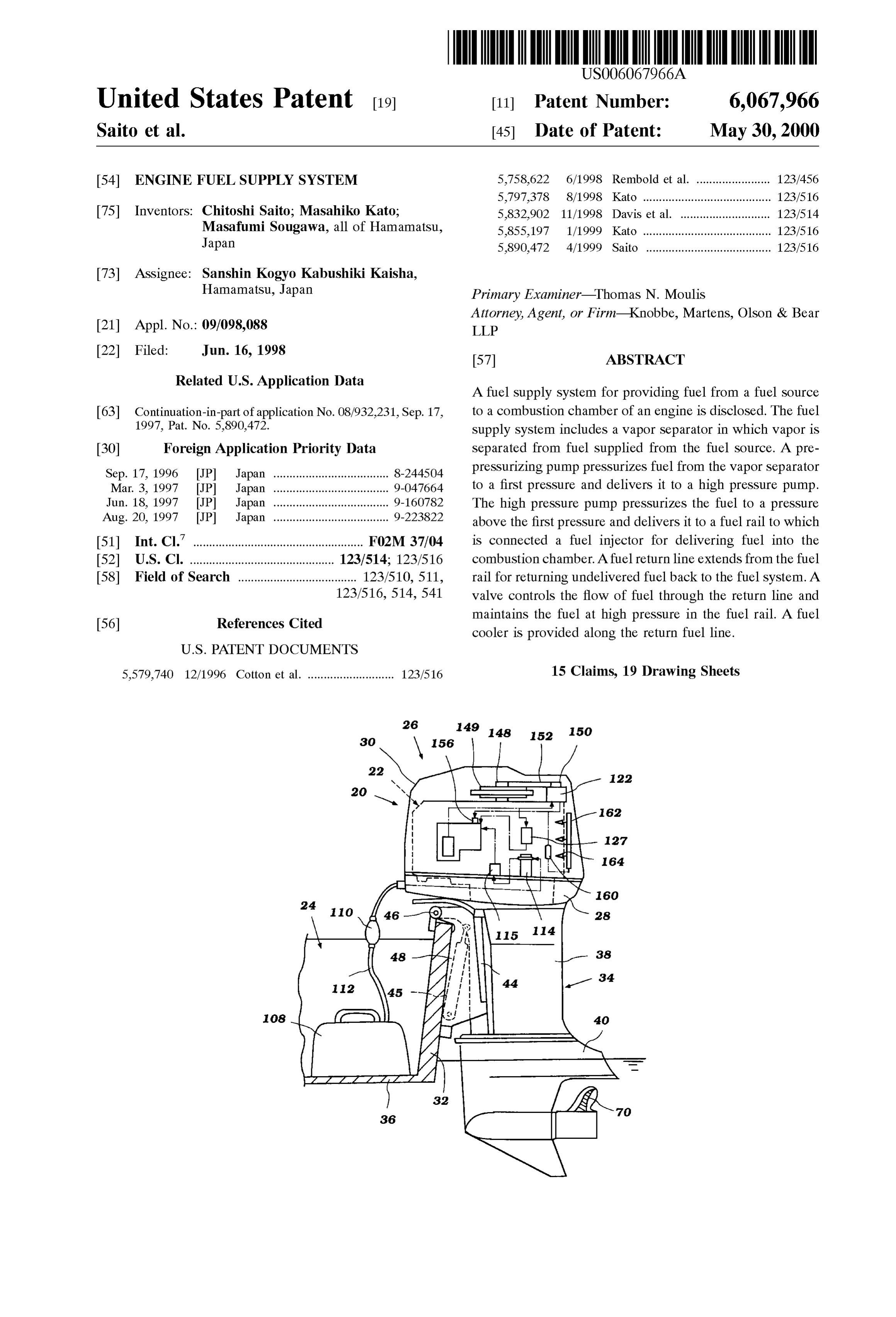
a large amount of fuel must be added to the air to compen sate for the loss of fuel flowing through the cylinder and BRIEF DESCRIPTION OF THE DRAWINGS directly out the exhaust port. Supplying excessive fuel, however, is costly and can result in Stalling of the engine. In 35 FIG. 1 is a side view of an outboard motor propelling a addition, the quantities of fuel flowing into the exhaust may watercraft, illustrated partially and in cross-section, the foul a catalyst positioned in the exhaust System. motor powered by an engine having a fuel Supply System in AS one attempt to Solve the above-Stated problems, Some accordance with the present invention and illustrated in two-cycle engines have been arranged to have fuel directly phantom;
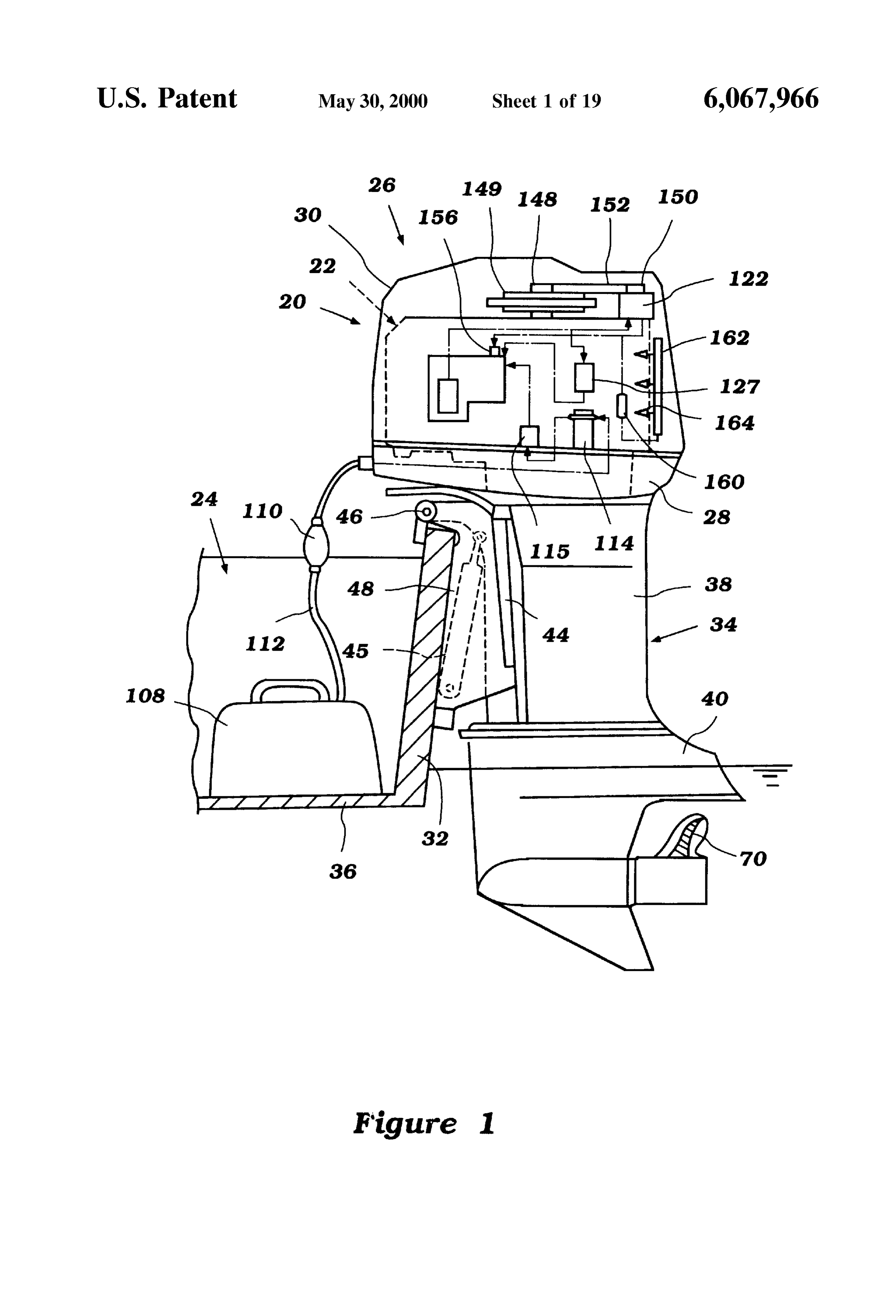
injected into the combustion chamber. A fresh air charge is 40 FIG. 2 is a cross-sectional view of the engine powering Supplied to each combustion chamber through the crankcase the motor illustrated in FIG. 1;
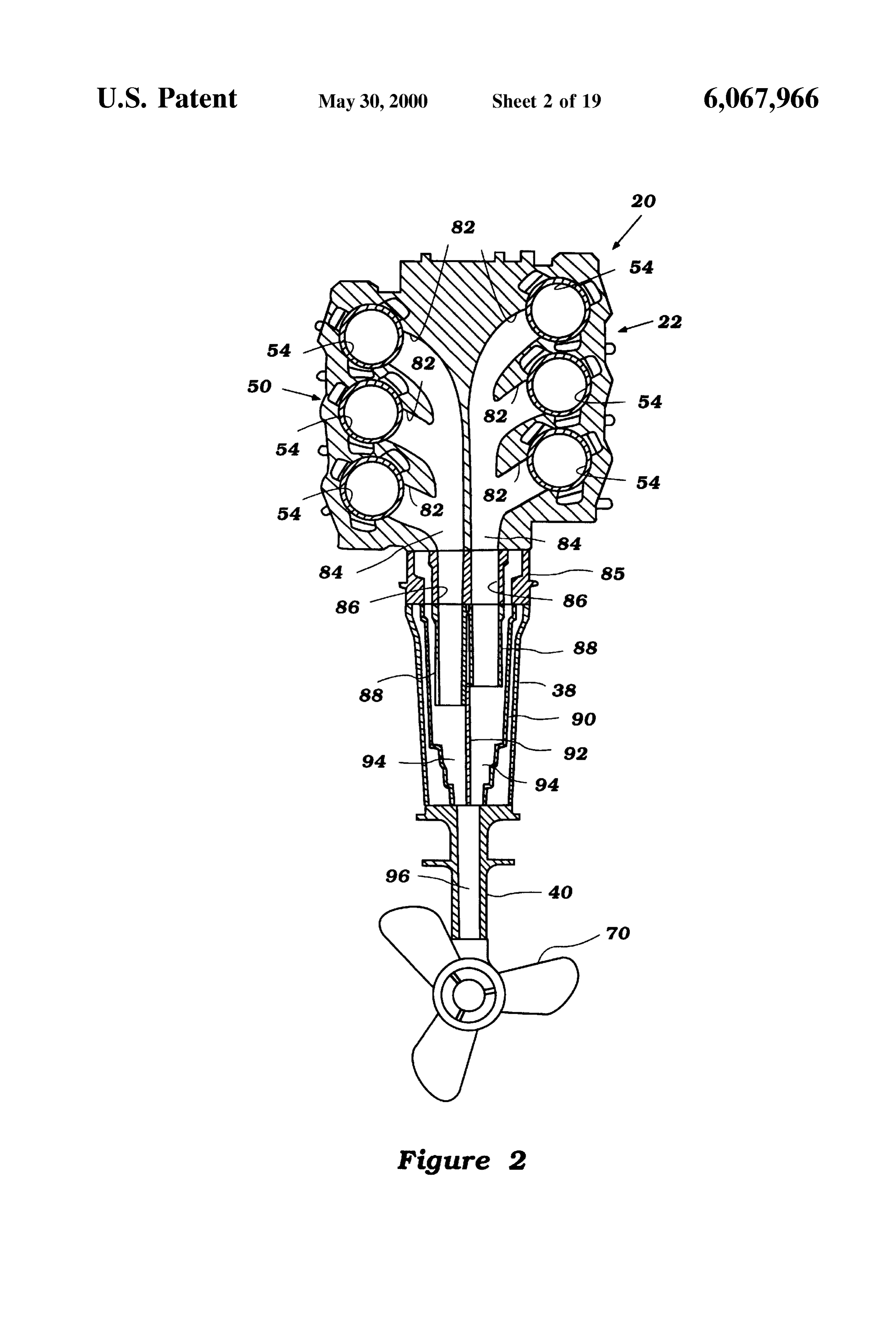
and a Scavenge port. Once air is Supplied to the combustion FIG. 3 is an enlarged cross-sectional view of a cylinder of chamber and the exhaust port is closed, a fuel injector injects the engine illustrated in FIG. 2;
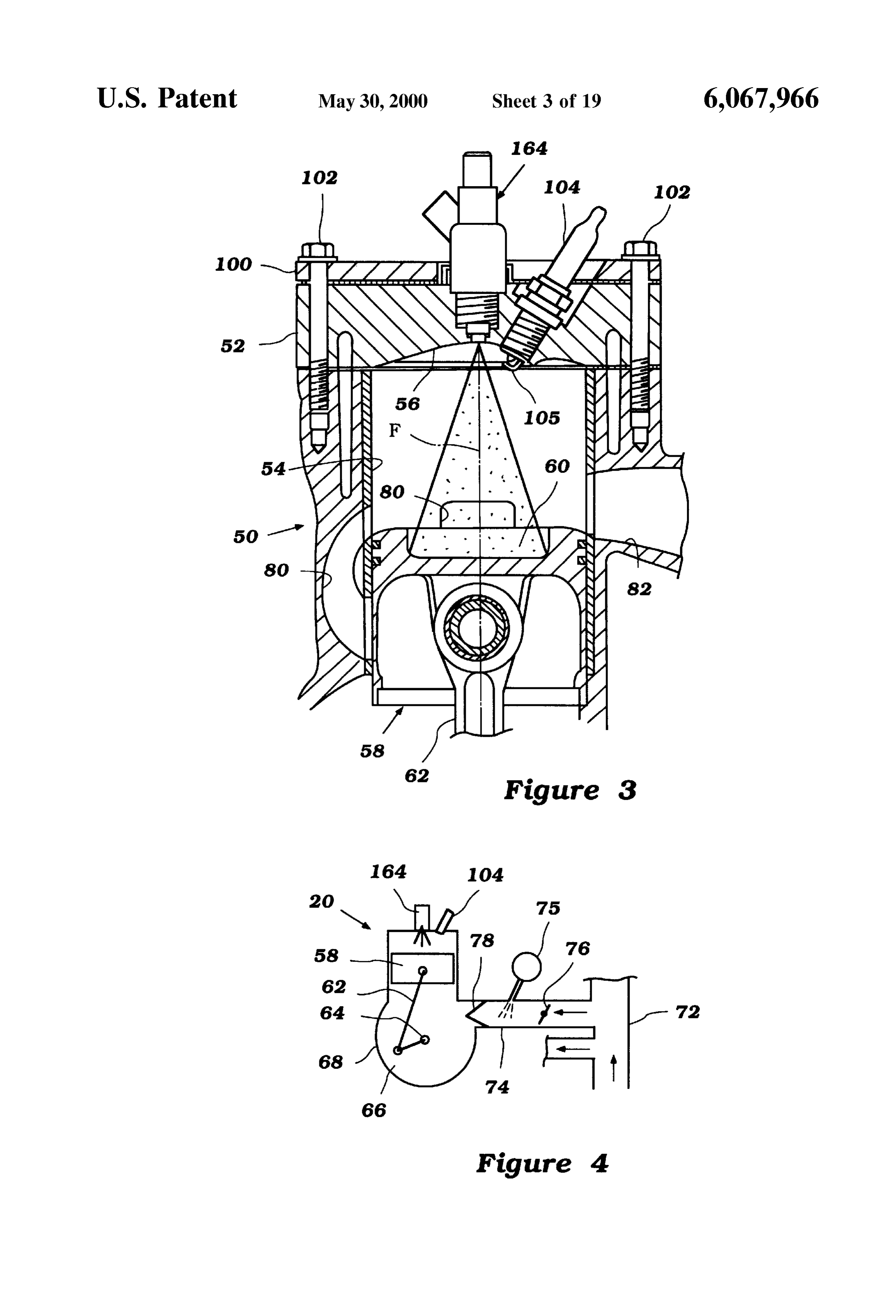
fuel directly into the combustion chamber for mixing with FIG. 4 is a Schematic illustrating the arrangement of the the air. 45 engine illustrated in FIG. 2;
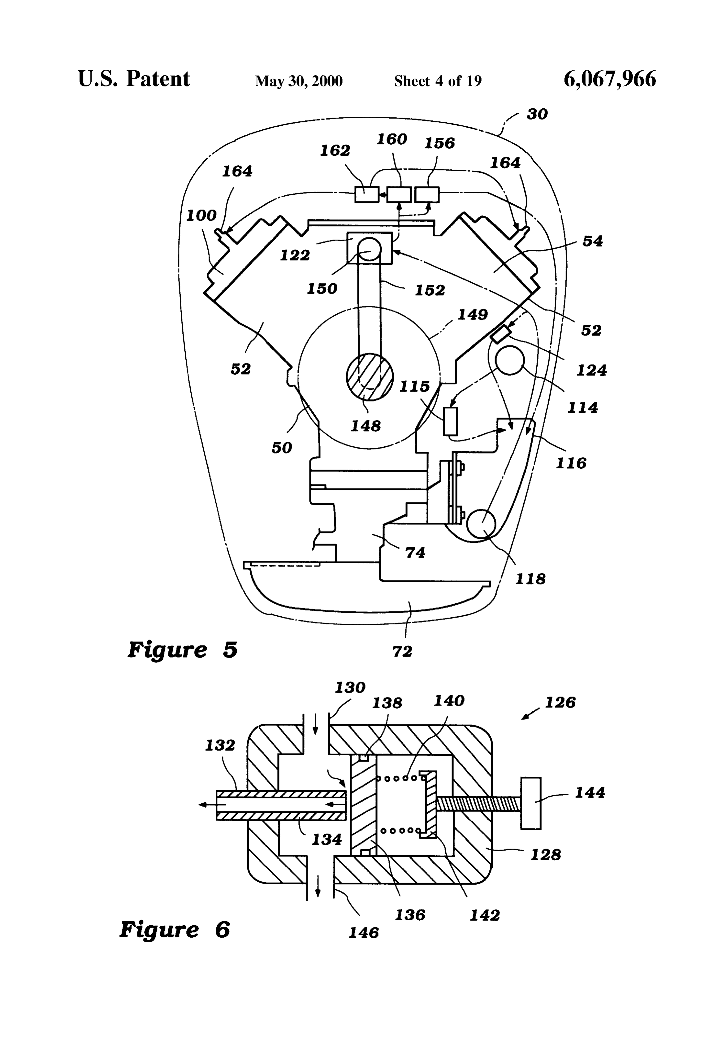
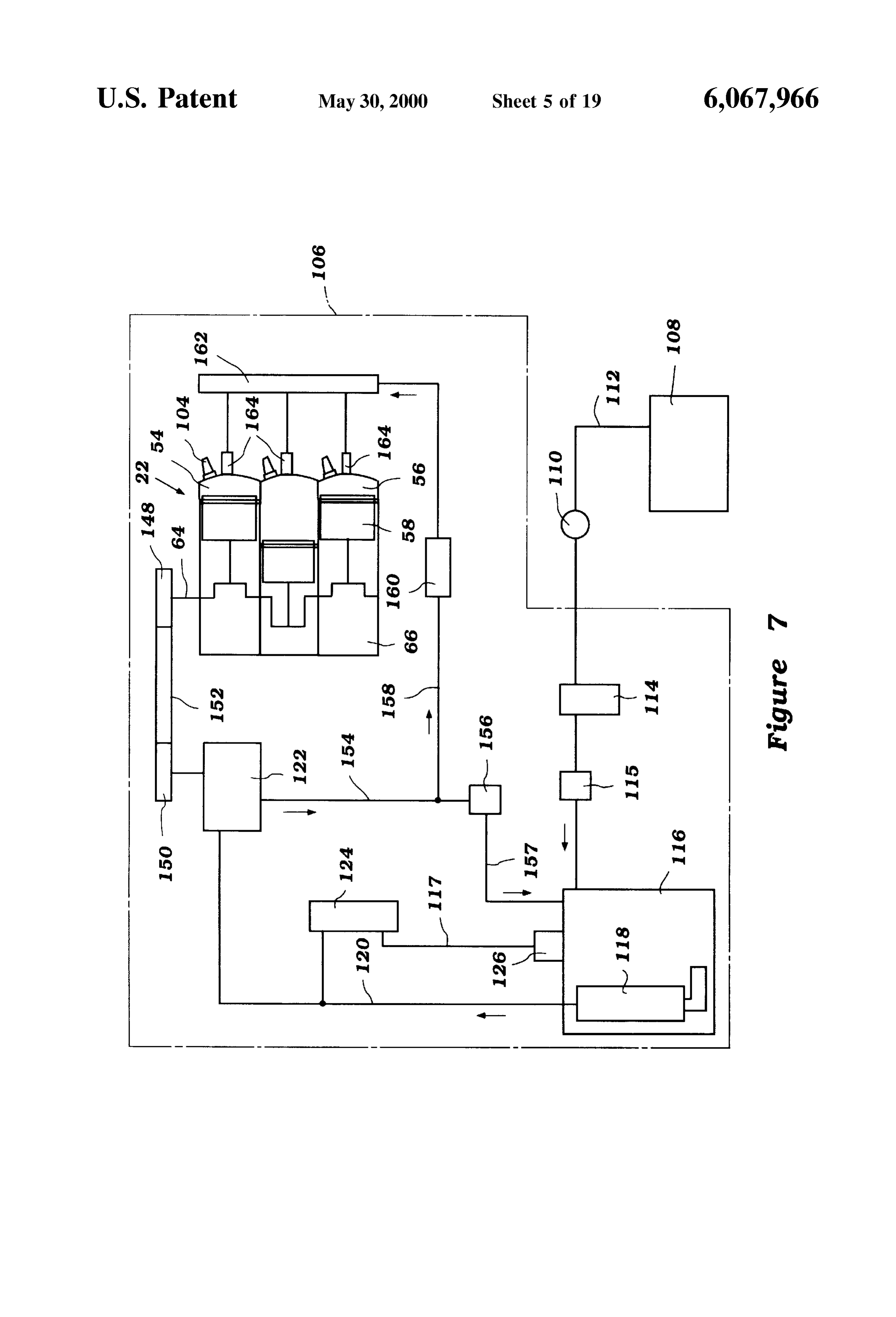
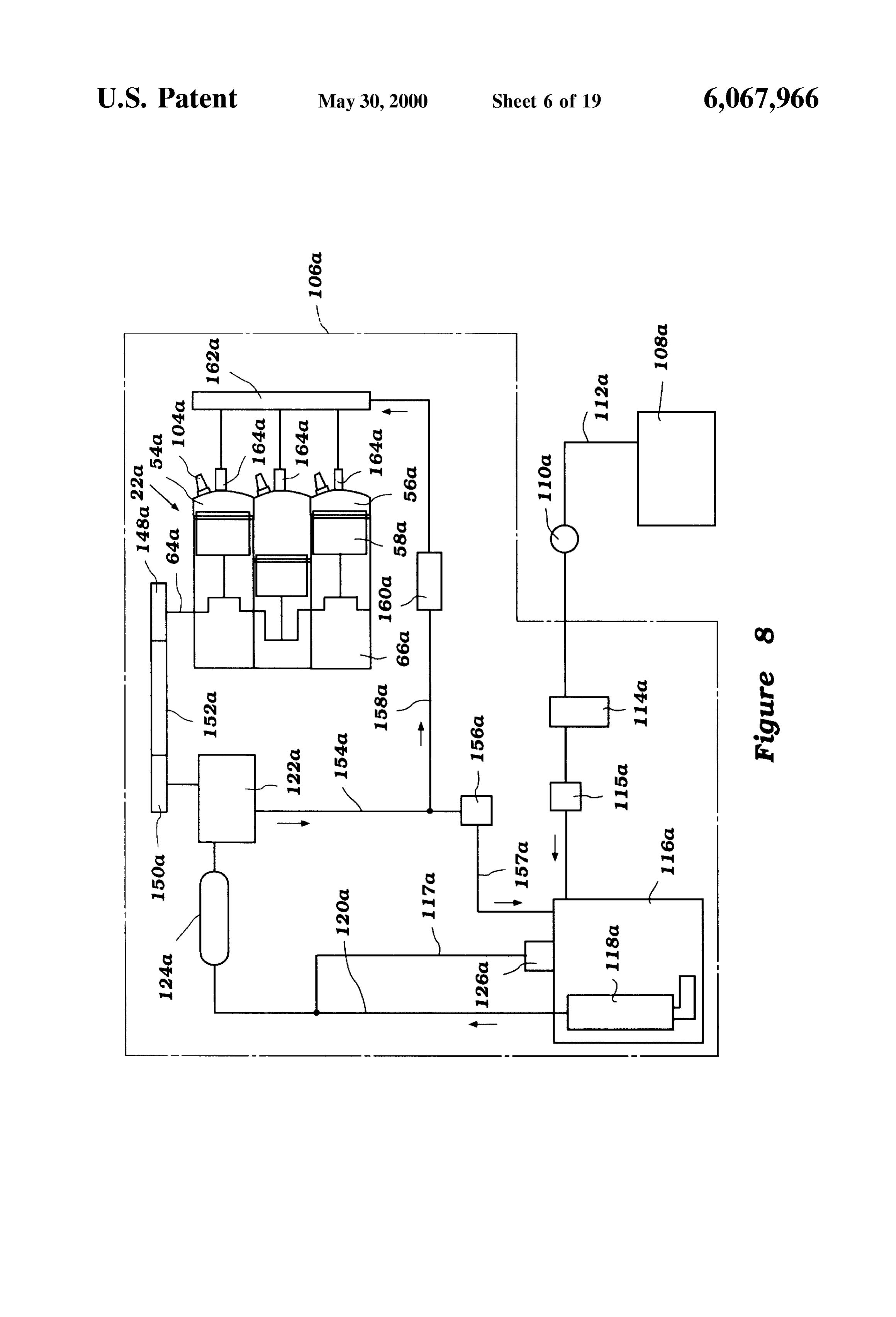
This arrangement has the benefit that little of the fuel FIG. 5 is a top view of the motor illustrated in FIG. 1, flows unburned into the exhaust System, and the amount of illustrating the engine having a fuel Supply System therein; fuel Supplied to each combustion chamber may be closely FIG. 6 is a cross-sectional view of a check valve of the controlled. On the other hand, in order for this system to fuel Supply system of the engine illustrated in FIG. 1; work, fuel must be Supplied to the fuel injector under high 50 FIG. 7 is a Schematic illustrating a fuel Supply System in preSSure. In particular, a large amount of fuel must be accordance with a first embodiment of the present invention. Sprayed into the combustion chamber in a short time, and in FIG. 8 is a Schematic illustrating a fuel Supply System in a manner which atomizes the fuel. Thus, these Systems have accordance with a Second embodiment of the present inven a fuel Supply which includes a fuel tank and a high pressure tion;
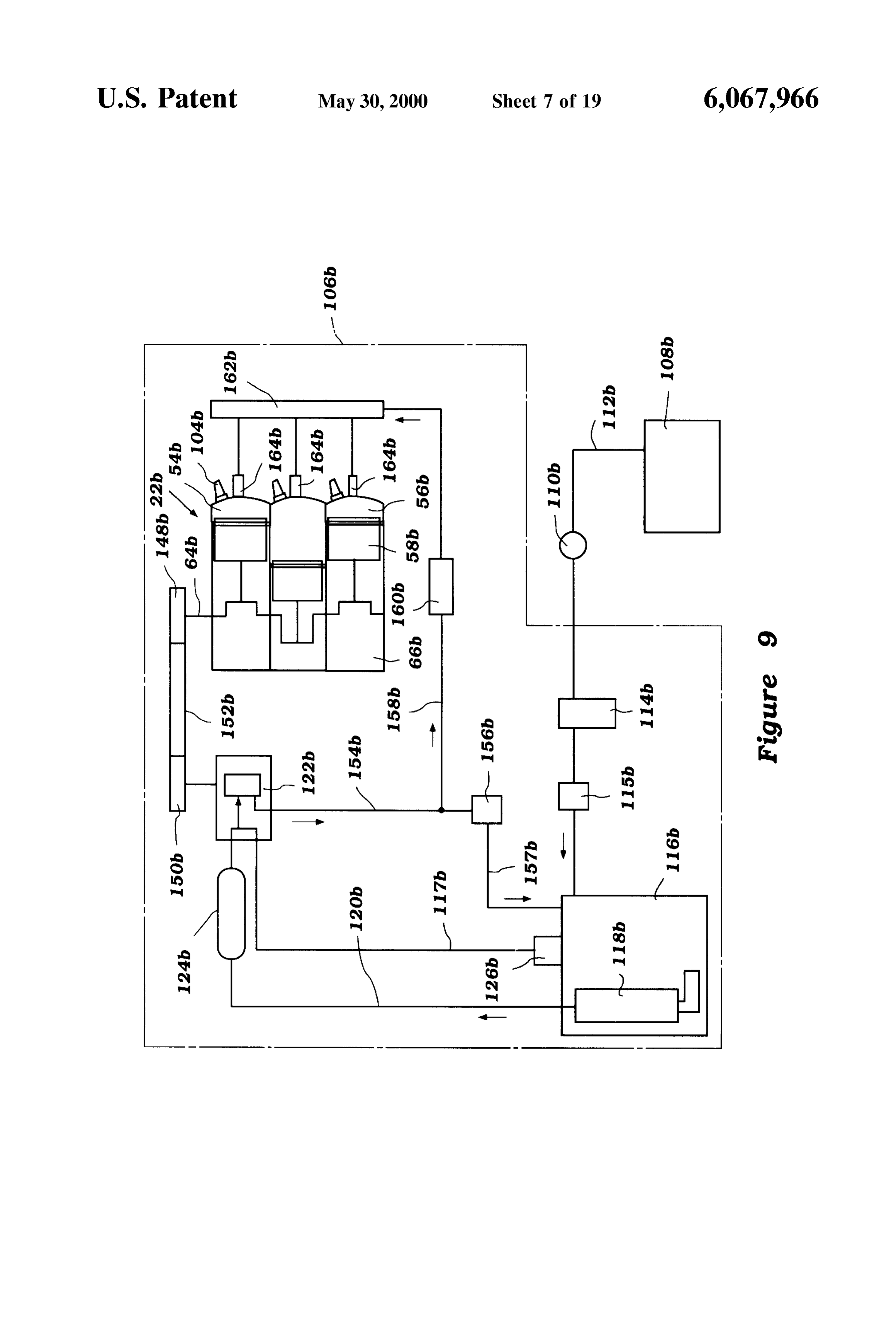
pump for pumping fuel from the tank and Supplying it under 55 high pressure to the fuel injector. FIG. 9 is a Schematic illustrating a fuel Supply System in A problem with this arrangementarises in pressurizing the accordance with a third embodiment of the present inven fuel from tank pressure (typically atmospheric pressure) to tion;
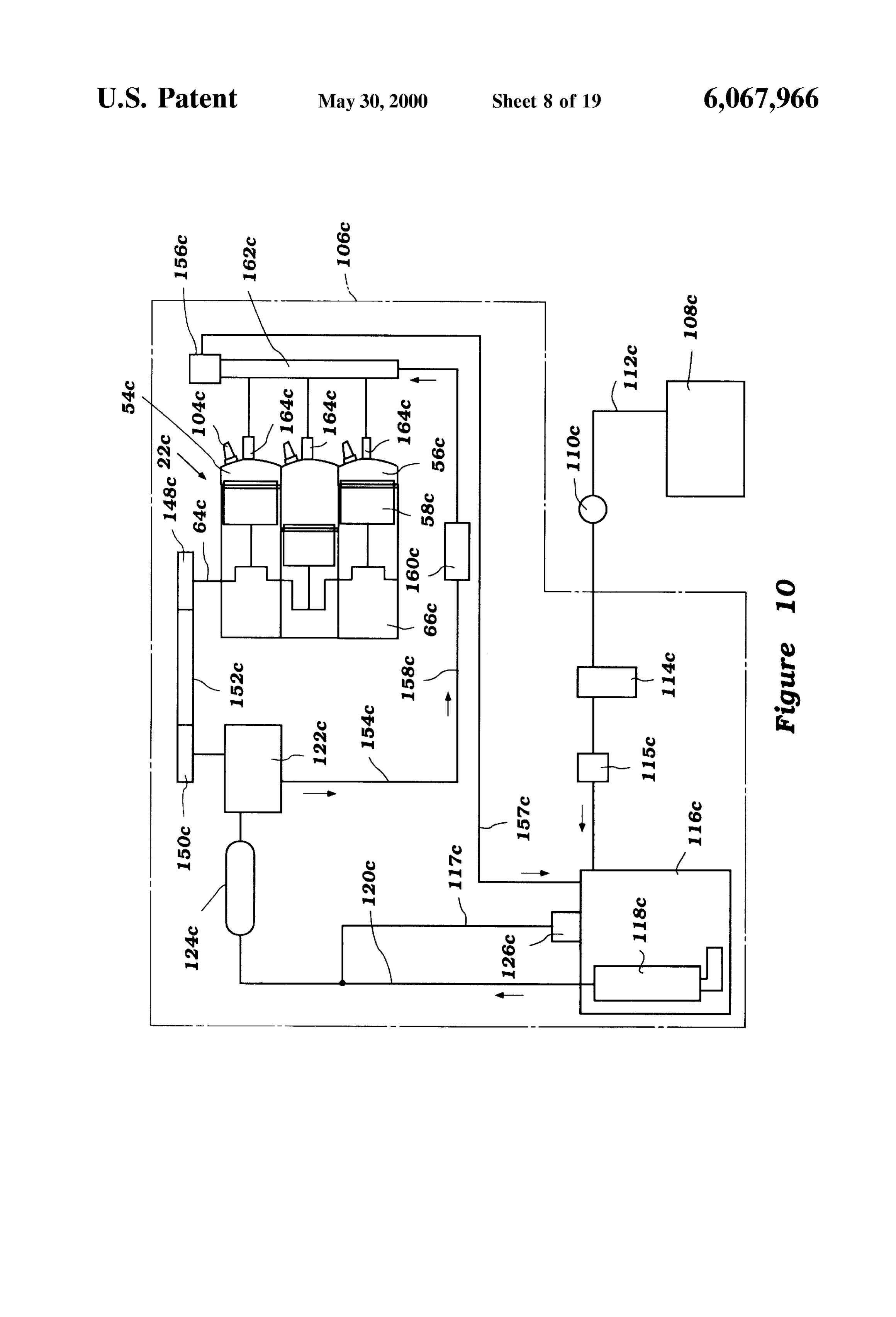
this high pressure by the high pressure pump. First, if a FIG. 10 is a schematic illustrating a fuel Supply system in Single pump is used, for the pump to create the large pressure 60 accordance with a fourth embodiment of the present inven head in the Single Step, its capacity must be very low and tion;
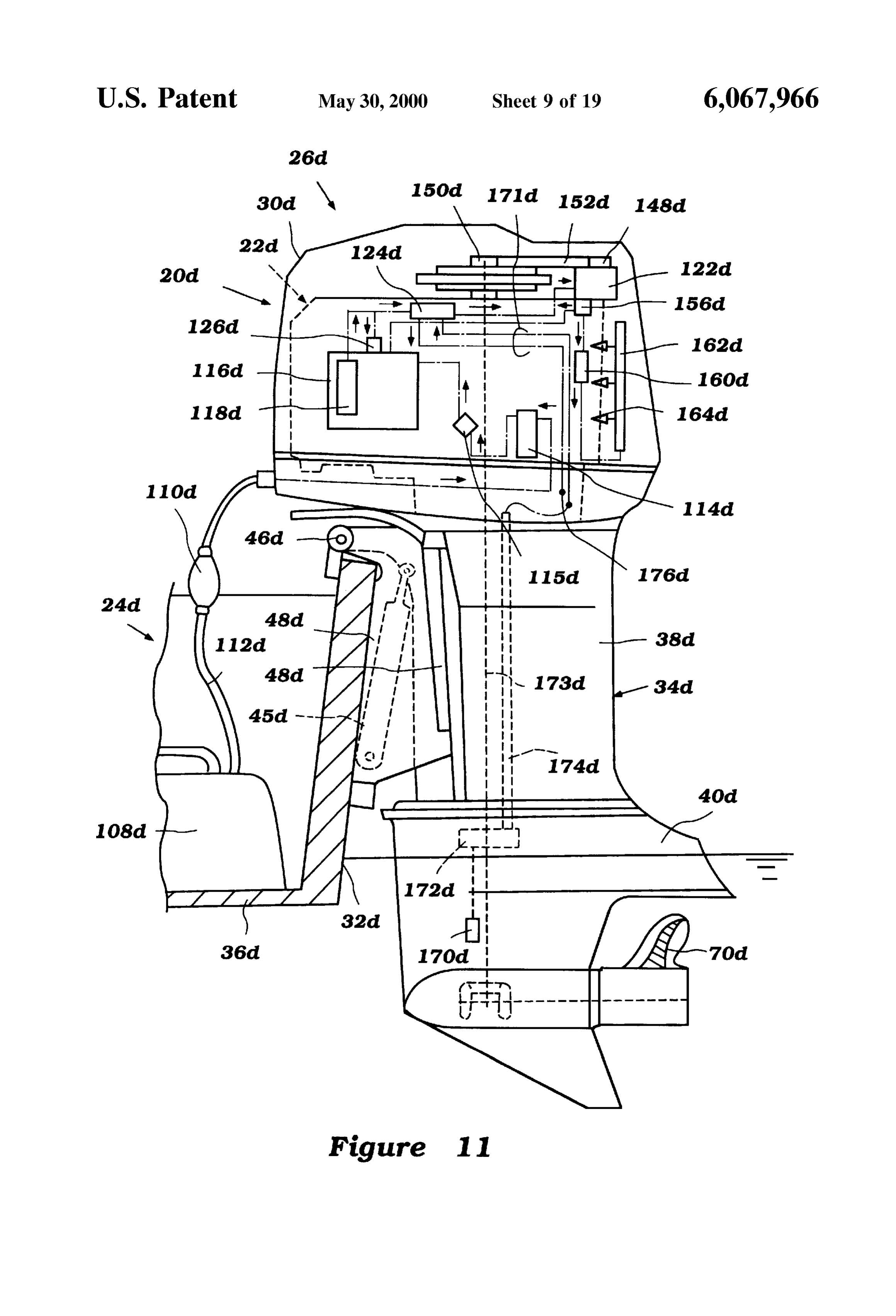
insufficient fuel may be Supplied to the engine. Another FIG. 11 is a side view of an outboard motor powered by problem is the introduction of large amounts of vapor into an engine having a fuel Supply System in accordance with the fuel. This vapor may cause a vapor lock in the System the present invention and including a first embodiment fuel and alters the amount of fuel which is actually delivered to 65 cooling arrangement;
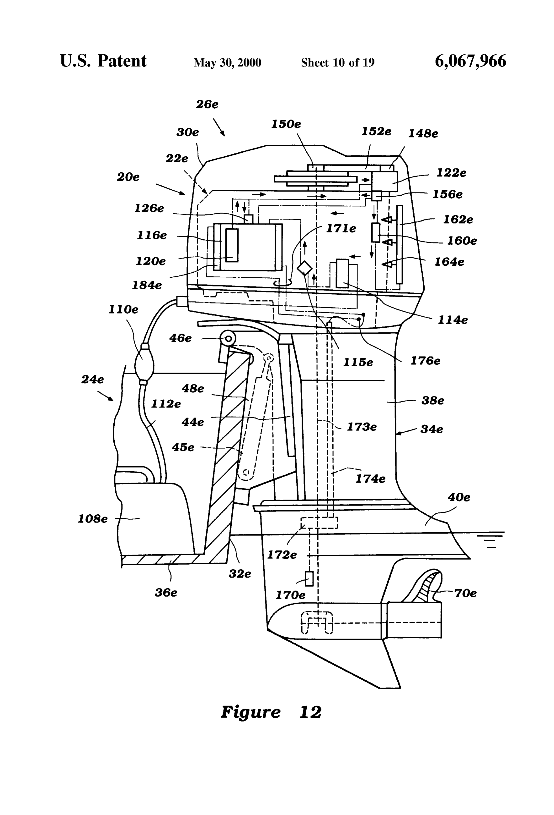
the combustion chamber during a desired fuel delivery time. FIG. 12 is a side view of an outboard motor powered by Thirdly, Such a high pressure pump must operate at high an engine having a fuel Supply System in accordance with
Page 22
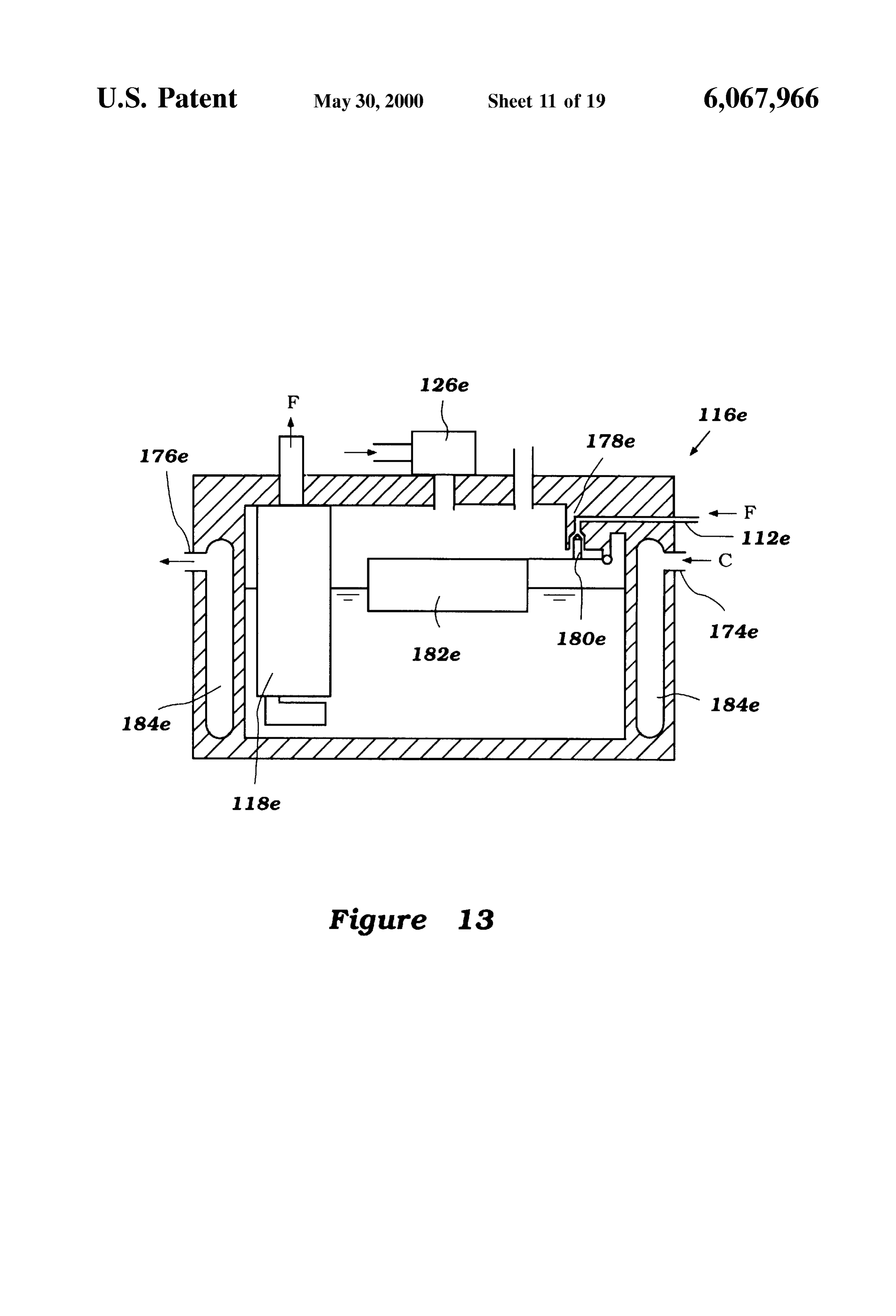
the present invention and including a Second embodiment for Steering movement about a vertically extending axis fuel cooling arrangement; within a swivel or steering bracket 44. The Swivel bracket 44 FIG. 13 is a cross-sectional view of a vapor Separator and is connected by means of a pivot pin 46 to a clamping fuel cooler of the fuel Supply System with fuel cooling bracket 48 which is attached to a transom portion 32 of a hull arrangement illustrated in FIG. 12; 36 of the watercraft 24. The pivot pin 46 permits the FIG. 14 is a Schematic illustrating a fuel Supply System in outboard motor 20 to be trimmed and tilted up about the accordance with a fifth embodiment of the present invention; horizontally filled cylinder disposed axis formed by the pivot pin 46. An oil 45 may be used to assist in this movement.
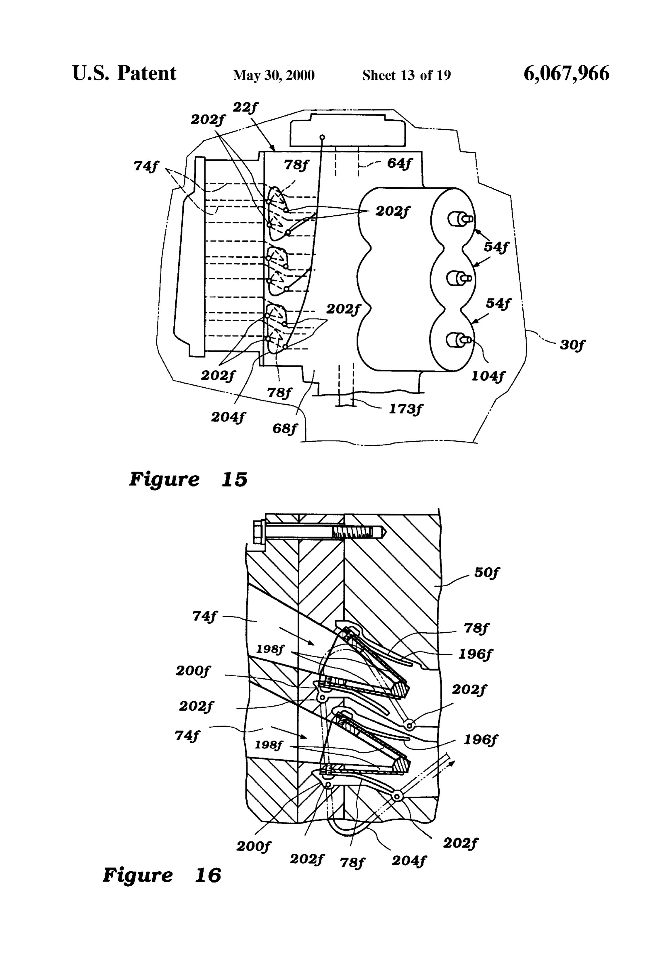
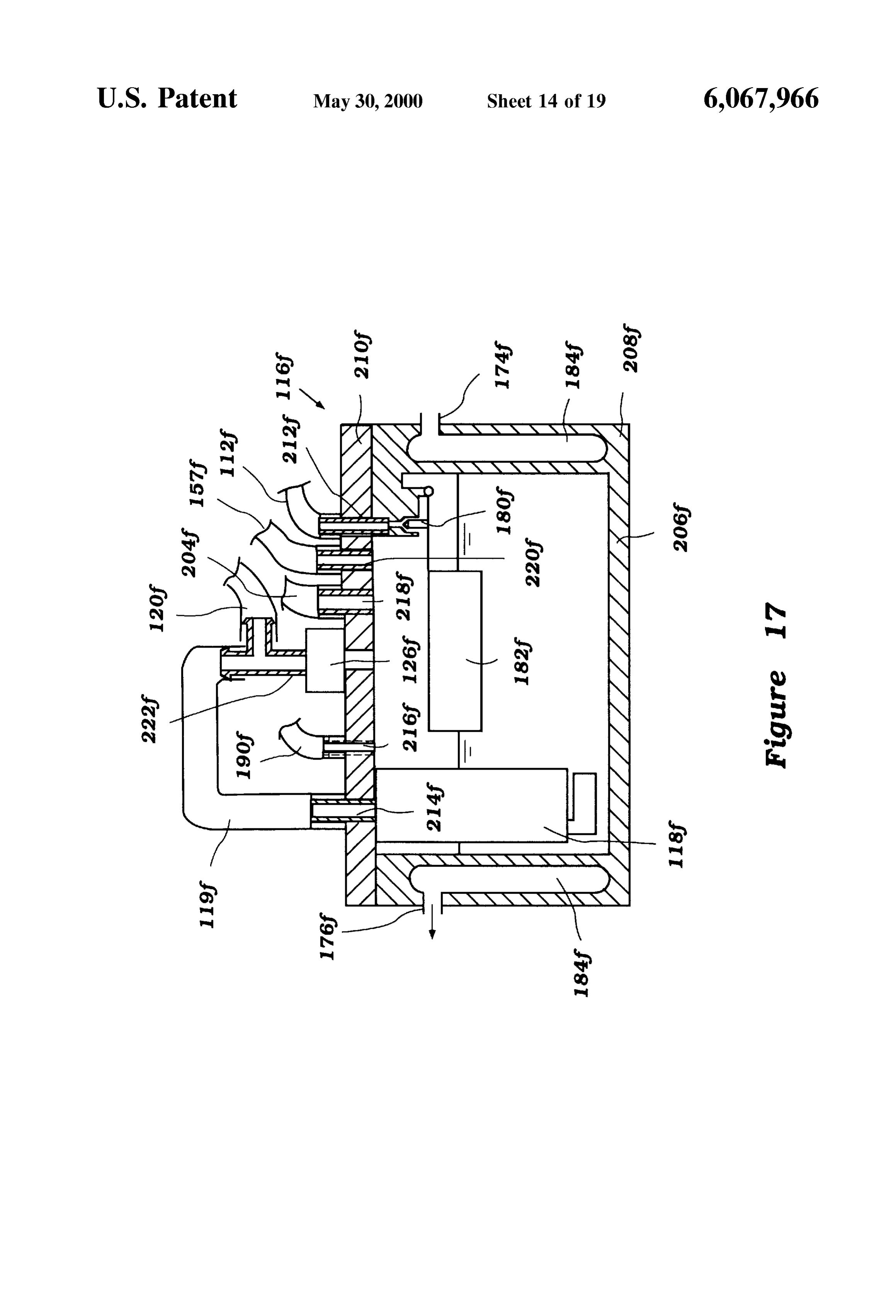
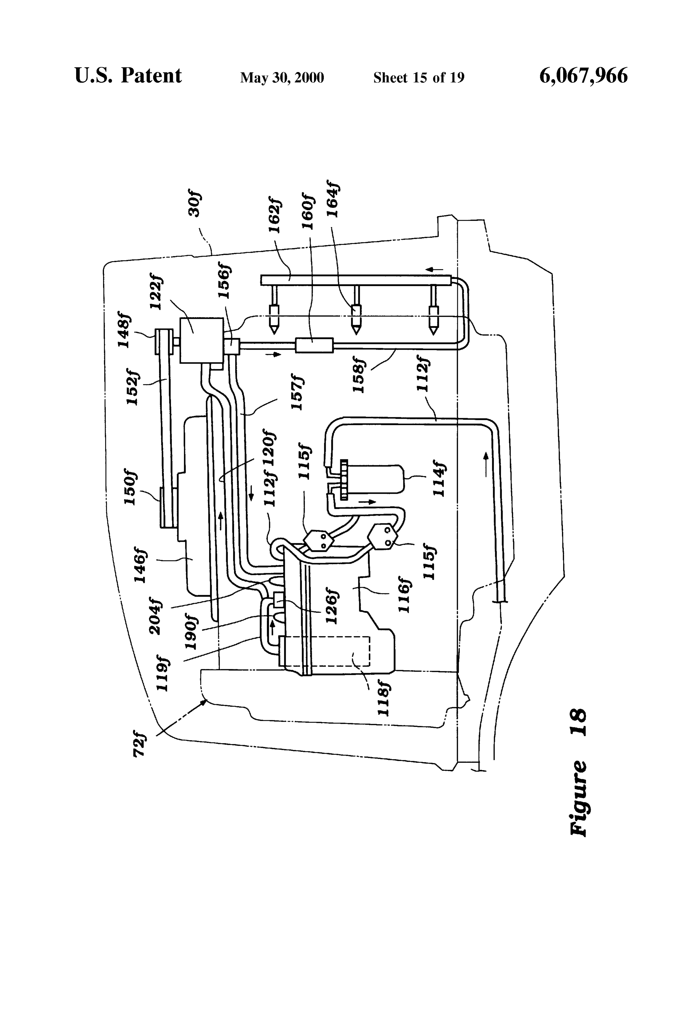
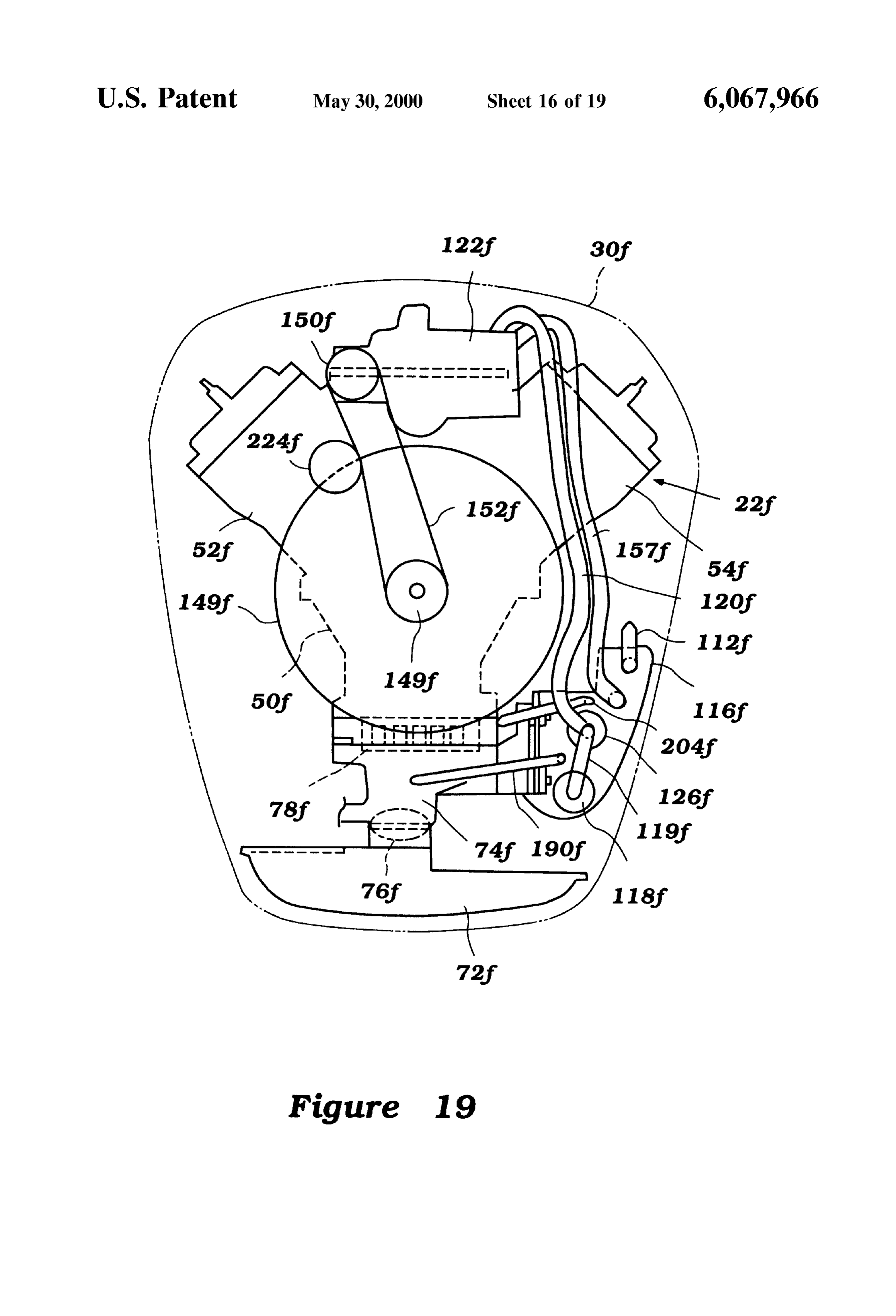
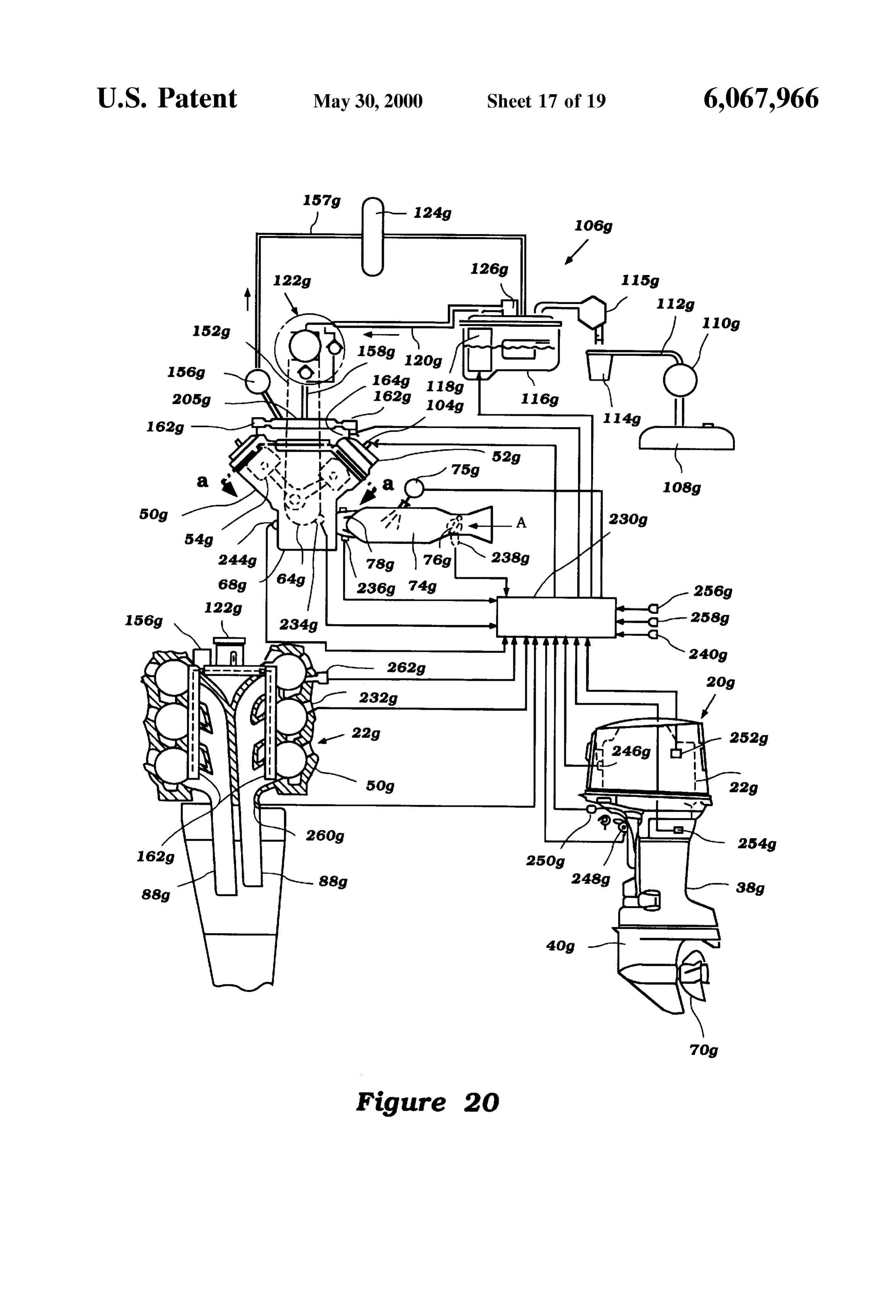
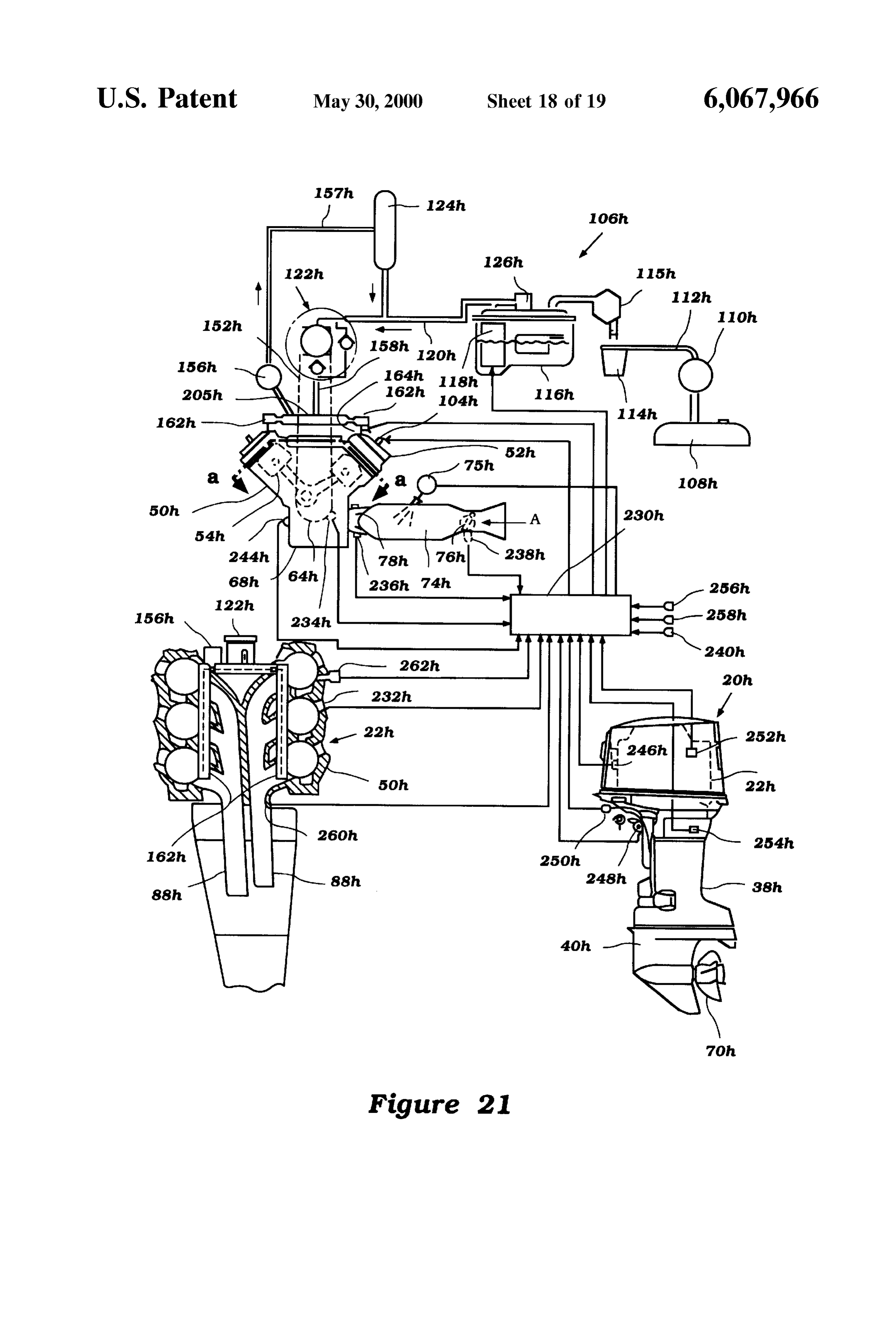
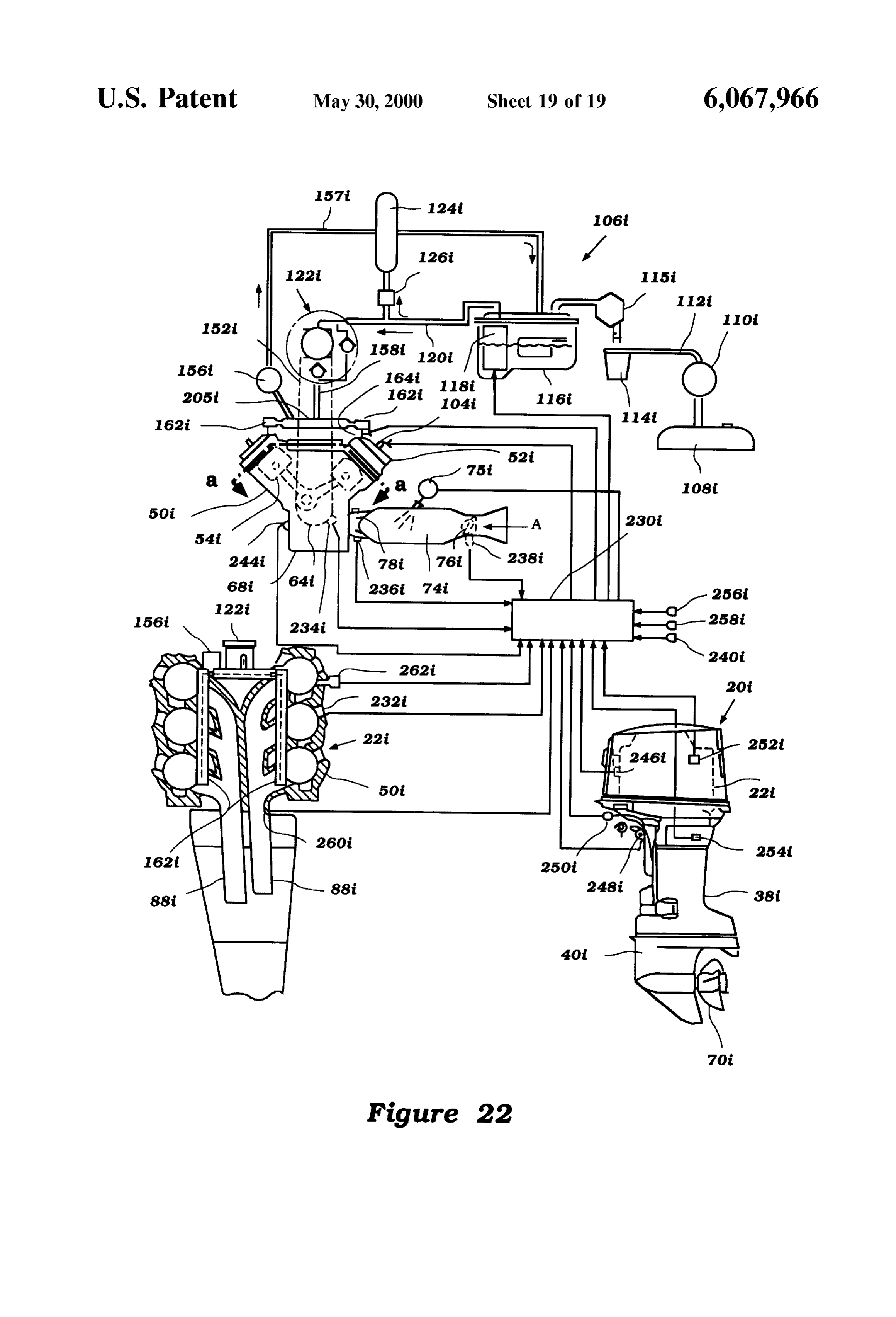
FIG. 15 is a side view of an outboard motor including an Referring to FIGS. 1 and 5, the engine 22 is positioned engine positioned in a cowling (illustrated in phantom) and within the cowling 30 of the motor 20. As best illustrated in including the fifth embodiment fuel Supply System; FIGS. 2 and 5, the engine 22 is preferably of the six-cylinder FIG. 16 is a partial cross-sectional view of the engine variety, operating on a two-cycle principle, and arranged in illustrated in FIG. 15; “V” fashion. In this arrangement, the engine 22 has a FIG. 17 is a cross-sectional view of a vapor Separator and cylinder block 50 with a pair of cylinder heads 52 connected fuel cooler of the fifth embodiment fuel Supply system of the 15 thereto. Each cylinder head 52 cooperates with the block 50 present invention; to define three cylinders 54. A combustion chamber 56 is FIG. 18 illustrates components of the fifth embodiment defined within each cylinder 54, preferably partly by a fuel System positioned within the cowling of the motor recessed area within the cylinder head 52. illustrated in FIG. 15; Referring to FIGS. 3 and 4, a piston 58 is movably FIG. 19 is a top view of the outboard motor illustrated in hasmounted within each cylinder 54. The piston 58 preferably FIG. 18, with a cowling thereof illustrated in phantom; a recessed top Surface area 60 of a shape known to those FIG. 20 schematically illustrates a fuel Supply system in skilled in the art for inducing fuel and air mixing within the cylinder 54. The piston 58 is connected by a connecting rod accordance with a sixth embodiment of the present invention 62 to a crankshaft 64. The crankshaft 64 is rotatably used to Supply fuel to an engine powering an outboard mounted in a crankcase 66 defined by the engine block 50 motor, the engine illustrated in a plan view and in a 25 and a crankcase cover 68 connected thereto. croSS-Sectional view taken along line a-a of the plan view, As illustrated in FIG. 2, the engine 22 is preferably and illustrating the outboard motor in a Side view, mounted within the cowling 30 so that its cylinders 54 are FIG. 21 schematically illustrates a fuel Supply system in generally horizontally extending. So arranged, the crank accordance with a Seventh embodiment of the present inven shaft 64 is generally vertically extending. The crankshaft 64 tion used to Supply fuel to an engine powering an outboard is arranged to drive a means for propelling the watercraft. motor, the engine illustrated in a plan view and in a Preferably, this means comprises a propeller 70. croSS-Sectional view taken along line a-a of the plan view, In this arrangement, the crankshaft 64 is connected to a and illustrating the outboard motor in a side view; and top end of a drive shaft (not shown) which extends down FIG. 22 Schematically illustrates a fuel Supply System in accordance with a eighth embodiment of the present inven 35 wardly gear and through the lower unit 34, where it drives a bevel a conventional forward-neutral-reverse transmis tion used to Supply fuel to an engine powering an outboard sion. A control (not shown) is preferably provided for motor, the engine illustrated in a plan view and in a allowing an operator croSS-Sectional view taken along line a-a of the plan view, from the watercraft 24.to remotely control the transmission and illustrating the outboard motor in a Side view. The transmission drives a propeller shaft (not shown)
DETAILED DESCRIPTION OF THE which is journalled within the lower section 40 of the lower PREFERRED EMBODIMENTS OF THE unit 34 in a known manner. A hub of the propeller 70 is INVENTION coupled to the drive shaft, rotation of the propeller moving In general, the present invention comprises a fuel Supply water which effectuates movement of the watercraft 24. System for an internal combustion engine. The fuel Supply 45 As illustrated in FIGS. 4 and 5, the engine 22 includes an System is arranged to deliver fuel at high preSSure for intake system for providing air to each cylinder 54. The injection into each combustion chamber of the engine, and intake manifold preferably includes an air intake 72. Air is yet is arranged to prevent the creation and delivery of vapor drawn from outside the cowling 30 of the motor through a within the fuel to the combustion chamber. vent (not shown) and into the air intake 72. Air passing Referring to FIG. 1, there is illustrated an outboard motor 50 through the air intake 72 is divided and passes through an 20 powered by an engine 22 and having a fuel Supply System intake passage 74 corresponding to each cylinder 54. in accordance with the present invention. The engine 22 Means are provided for controlling the flow rate of air to having the fuel Supply System is described for use with an each cylinder 54. In the present embodiment, this means outboard motor 20 Since this particular application is one for comprises a throttle valve 76 movably positioned in each which the engine 22 described is particularly useful. It 55 passage 74. Each valve 76 preferably comprises a butterfly should be understood, however, that the engine 22 which is type valve which is controlled remotely by the operator of Supplied with fuel with the fuel Supply System arranged as the watercraft 24.
described may be used in other applications. Each intake passage 74 leads to a chamber within the As illustrated in FIG. 1, the outboard motor 20 is of the crankcase 66 corresponding to one of the cylinders 54. A type utilized to propel a watercraft 24. The outboard motor 60 reed-valve 78 is preferably provided in each intake passage 20 has a powerhead area 26 comprised of a lower tray 74 for permitting only one-way passage of the air into each portion 28 and a main cowling portion 30. The motor 20 crankcase chamber.
includes a lower unit 34 extending downwardly from the Lubricant may be added to the air passing through the cowling portion 30. The lower unit 34 comprises an upper or intake passage 74 by a lubricant delivery mechanism 75, as “drive shaft housing” section 38 and a lower section 40. 65 well known to those of skill in the art. The powerhead area 26 of the motor 20 is connected to a AS Stated above, the engine 22 operates on the well known Steering shaft (not shown). The Steering shaft is Supported two-cycle principle. AS Such, during a crankcase compres
Page 23
S 6
Sion cycle, air within the crankcase chamber is compressed creation within the fuel during the preSSurizing by the high and flows through one or more Scavenge passageS 80 leading pressure pump 122 may be minimized. Preferably, this from the chamber into the cylinder 54. means comprises a fuel cooler 124. AS described in more detail below, a fuel Supply System In accordance with this embodiment, a portion of the fuel provides fuel to each cylinder 54 for combustion therein delivered by the pump 118 through the line 120 is diverted with the air Supplied as Stated above. through the fuel cooler 124 and returned to the vapor Referring to FIG. 2, exhaust generated during the com separator 116 through a return line 117. As illustrated, the bustion process is routed from each cylinder 54 through an amount of fuel diverted is determined by a Setting of a exhaust port 82. Each exhaust port 82 comprises a passage pressure-regulator type check valve 126. The fuel cooler 124 leading through the engine block 50 from cylinder 54. The thus cools fuel which is mixed with the fuel in the vapor exhaust ports 82 for the cylinders 54 of each bank join into Separator 116, thus lowering the temperature of the fuel a common exhaust passage 84. The common exhaust pas therein which is delivered to the high pressure pump 122. sages 84 lead downwardly to the bottom end of the engine The valve 126 controlling the amount of fuel diverted 22. through the fuel cooler 124 is illustrated in more detail in Means are provided for routing the exhaust from the 15 FIG. 6. As illustrated therein, the valve 126 has a body 128 bottom of the engine 22 to a point external to the motor 20. defining a chamber having at least one inlet 130 and an Preferably, the engine 22 is positioned above an exhaust outlet 132. The outlet 132 is defined by a pipe 134 extending guide 85 within the motor 20. A pair of passages 86 extend into the chamber. A piston member 136 is movably posi through the exhaust guide 85 corresponding to the common tioned in the chamber adjacent an end of the pipe. The piston exhaust passageS 84 leading through the engine 22. 136 is sealed by an O-ring 138 or similar seal, preventing A muffler 90 is positioned in the upper section 38 of the fuel from flowing therepast to the portion of the chamber on lower unit 34. An exhaust pipe 88 extends down from each the opposite Side thereof.
passage 86 through the exhaust guide 85 into the muffler 90 The piston 136 is biased in the direction of the end of the for directing the exhaust into the muffler 90. Exhaust from 25 pipe 134 by a spring 140. An opposite end of the spring 140 each exhaust pipe 88 is kept separate by a divider 92, with is positioned against a retainer 142 mounted on the end of an the exhaust from each exhaust pipe 88 directed into one of adjuster 144. The spring 140 presses the piston 136 in the two exhaust expansion areas 94 defined within the muffler direction of the end of the pipe 134, thereby having the 90. The exhaust is routed from the muffler 90 through an natural tendency to close the end of the pipe 134 and prevent exhaust passage 96 extending through the lower Section 40 the flow of fuel from the inlet 130 through the chamber and of the lower unit 40 to a through the hub exhaust discharge, out the outlet, in which case the fuel may be returned to the as is well known in the art. supply through an alternative relief outlet 146. As illustrated in FIG. 3, a cover 100 extends over each When the fuel pressure within the chamber reaches a cylinder head 52. Bolts 102 or other fasteners are used to Sufficient level, the Spring force is overcome and the piston connect the cover 100, head 52 and block 50. 35 134 is moved from the end of the pipe 134, permitting fuel Referring to FIG. 3, means are provided for igniting the to flow through the outlet 132 (and, for example, to the vapor air and fuel supplied to each cylinder 54. Preferably, this separator 118).
means comprises a spark plug 104 having its electrode 105 The adjuster 144, which threadingly engages the housing positioned within the combustion chamber 56 of the cylinder 128, may be used to move the retainer 142 towards and away 54. An ignition circuit, as is known to those skilled in the art, 40 from the end of the pipe 134. As may be understood, the is provided for inducing a spark at the electrode tip 105 of closer the retainer 142 is moved to the end of the pipe 134, the Spark plug 104 at a determined time for igniting an air the greater the Spring force and thus the higher the fuel and fuel mixture within the cylinder 54. preSSure which must be achieved to permit flow through the In accordance with the present invention, a fuel Supply outlet 132.
system 106 provided fuel to each cylinder 54 for combustion 45 As illustrated in FIGS. 5 and 7, the high pressure fuel therein. A fuel Supply system 106 in accordance with a first pump 122 is preferably driven by the crankshaft 64 of the embodiment of the invention will be described with refer engine 22. In particular, a drive pulley 148 is mounted on the ence initially to FIGS. 1 and 7. crankshaft 64 above a flywheel 149. A similar pulley 150 is The fuel Supply system 106 draws fuel from a fuel supply positioned on a drive shaft of the pump 122. A belt 152 or Source, Such as a fuel tank 108 or reservoir. As illustrated, 50 extends between the pulleys 148,150, whereby the drive the tank 108 is positioned within the hull 36 of the watercraft pulley 148 drives the pump 122.
24. A first low preSSure or primer type pump 110 is posi The pump 122 pressurizes the fuel to a Second pressure tioned along a fuel delivery line 112 leading from the tank above the first pressure and delivers it through a line 154. In 108. The delivery line 112 leads to a fuel filter 114, and accordance with the present invention, a portion of the fuel thereon to a Second low pressure pump 115 and then a vapor 55 Supplied by the pump 122 is returned back to the vapor separator 116. Preferably, the second pump 114 is of the separator 116. Preferably, the fuel is diverted by a pressure electrically operated variety. activated valve 156 back to the vapor separator 116 through The vapor separator 116 is utilized to remove air from the a line 157. This valve 156 is similar to that illustrated in FIG. fuel, as is known in the art. The fuel is then pumped by a first 6 and described above.
or pre-pressurizing pump 118 through a line 120 to a high 60 The remainder of the fuel is delivered through a main pressure pump 122. The pump 118 is preferably of the delivery line 158 through a fuel filter 160 to a high pressure electrically-operated type and positioned within the vapor fuel rail 162. A fuel injector 164 is provided corresponding separator 116. The first pump 118 pressurizes the fuel to a to each cylinder 54, as illustrated in FIG. 3, and is arranged first pressure above the pressure of the fuel within the vapor to spray fuel F into the cylinder 54. The fuel injector 164 is separator 116. 65 arranged to draw fuel from the fuel rail 162. Means are provided for cooling at least a portion of the In accordance with the fuel Supply system 106 of the fuel Supplied to the high pressure pump 122, whereby vapor present invention the pump 118 pre-pressurizes the fuel, So
Page 24
that the high pressure pump 122 need not further pressurize In addition to the advantages described above, this the fuel in as great of a preSSure rise to reach the desired fuel embodiment has the further advantage that the valve 156c Supply pressure. Because the degree to which the high which is used to return a portion of the fuel to the vapor preSSure pump 122 must pressurize the fuel is reduced, the Separator 116c is also utilized to control the pressure within amount of vapor produced during the preSSurizing Step is the fuel rail 162c.
minimized. FIG. 11 illustrates an outboard motor 20d having a fuel In addition, the fuel cooler 124 lowers the temperature of Supply System 106d with a Specific fuel cooling arrange the fuel flowing through the fuel System. LeSS Vaporization ment. With the exception of the fuel cooling arrangement, or air-entry into the low temperature fuel occurs. the fuel Supply system 106d is similar to that illustrated in In this embodiment, the valve 156 diverts a portion of the FIG.8. Like reference numerals are used with to designate Similar parts in the description and illustration of this fuel back to the vapor separator 116. The valve 156 is useful embodiment in diverting what little vapor may be present in the System to those of the embodiment illustrated in FIG. back to the Separator 116 for Separation, with the remaining 8, except that a “d” designator has been added thereto. fuel being delivered to the fuel injectors 164. In this embodiment, the fuel is cooled in the fuel cooler 15 124d by cooling water drawn from the body of water in
A second embodiment fuel Supply system 106a is illus which the motor 20d is operating. trated in FIG. 8. In the description and illustration of this embodiment, Similar parts have been given like reference AS illustrated, cooling water is drawn through an inlet numerals to those used in the embodiment described above 170d in the motor 20d by a pump 172d. The pump 172d is and illustrated in FIGS. 1-7, except that an “a” designator preferably powered off of a drive shaft 173d extending has been added thereto. between the crankshaft of the engine 22d and the transmis AS illustrated, this embodiment System is Similar to the Sion. one
Water is delivered through a delivery line 174d through or more coolant passages 171d to the fuel cooler 124d.
last. In this embodiment, however, a portion of the fuel This water delivered by the pump 118a through the line 120a is returned cooler 124d,is and used to cool the fuel passing through the fuel then is drained back to the body of water directly back to the vapor separator 116a (as governed by a 25 in which the motor 20d is operating through one or more valve 126a) without passing through a fuel cooler. Instead, coolant passages 171d leading to a drain port 176d. a fuel cooler 124a is positioned along the portion of the line This arrangement has the advantage that the fuel is cooled 120a leading to the high pressure pump 122a, cooling the fuel which is delivered directly thereto. before delivery to the fuel injectors 164d. In addition, since In addition to those advantages described above, this most outboard motors have their engines provided with a liquid cooling System already, Simply by providing a Small embodiment fuel supply system 106a has the further advan amount of this coolant to a fuel cooler, the fuel cooling tage that all of the fuel delivered to the high pressure pump advantages are achieved.
122a is cooled.
Another fuel cooling arrangement is illustrated in FIGS.
A third embodiment fuel Supply system 106b is illustrated 12 and 13. In the description and illustration of this
in FIG. 9. In the description and illustration of this embodiment, like reference numerals have been utilized for embodiment, Similar parts have been given like reference like parts to those of the embodiments described and illus numerals to those used in the above embodiments illustrated trated above, except than an “e' designator has been added in FIGS. 1-8, except that a “b” designator has been added thereto.
thereto.
In this embodiment, the fuel is cooled within the vapor
In this embodiment, the fuel pump 118b delivers fuel 40 Separator 116e. In this arrangement, the Separator 116e through a fuel line 120b to a fuel cooler 124b and thereon to includes a housing 178e. Fuel is delivered through the fuel the high preSSure fuel pump 122b. In this embodiment, a line 112e to the separator 116e. Preferably, the rate of fuel portion of the fuel delivered to the pump 122b is diverted delivery is controlled by a control pin 180e actuated by a back to the vapor separator 116b through a return line. The 45 float 182e in the separator 116e. When the separator 116e is amount of fuel returned is governed by a valve 126b similar full, the float 182e rises upwardly, forcing the pin 180e to that described above and illustrated in FIG. 6. upwardly as well, blocking the incoming fuel line. This embodiment fuel Supply system 106b has the advan A water or cooling jacket 184e is formed within the body tage that vapor within the fuel delivered to the high pressure 178e of the separator 116e. Coolant “C” is delivered through pump 122b is diverted back to the vapor separator 116b 50 the delivery line 174e into the jacket 184e. The coolant flows before being further preSSurized by the high preSSure pump through the jacket 184e, cooling the fuel within the Separator 122b. 116e, and then flows out an outlet to the discharge port 176e, A fourth embodiment fuel Supply system 106c is illus as described above.
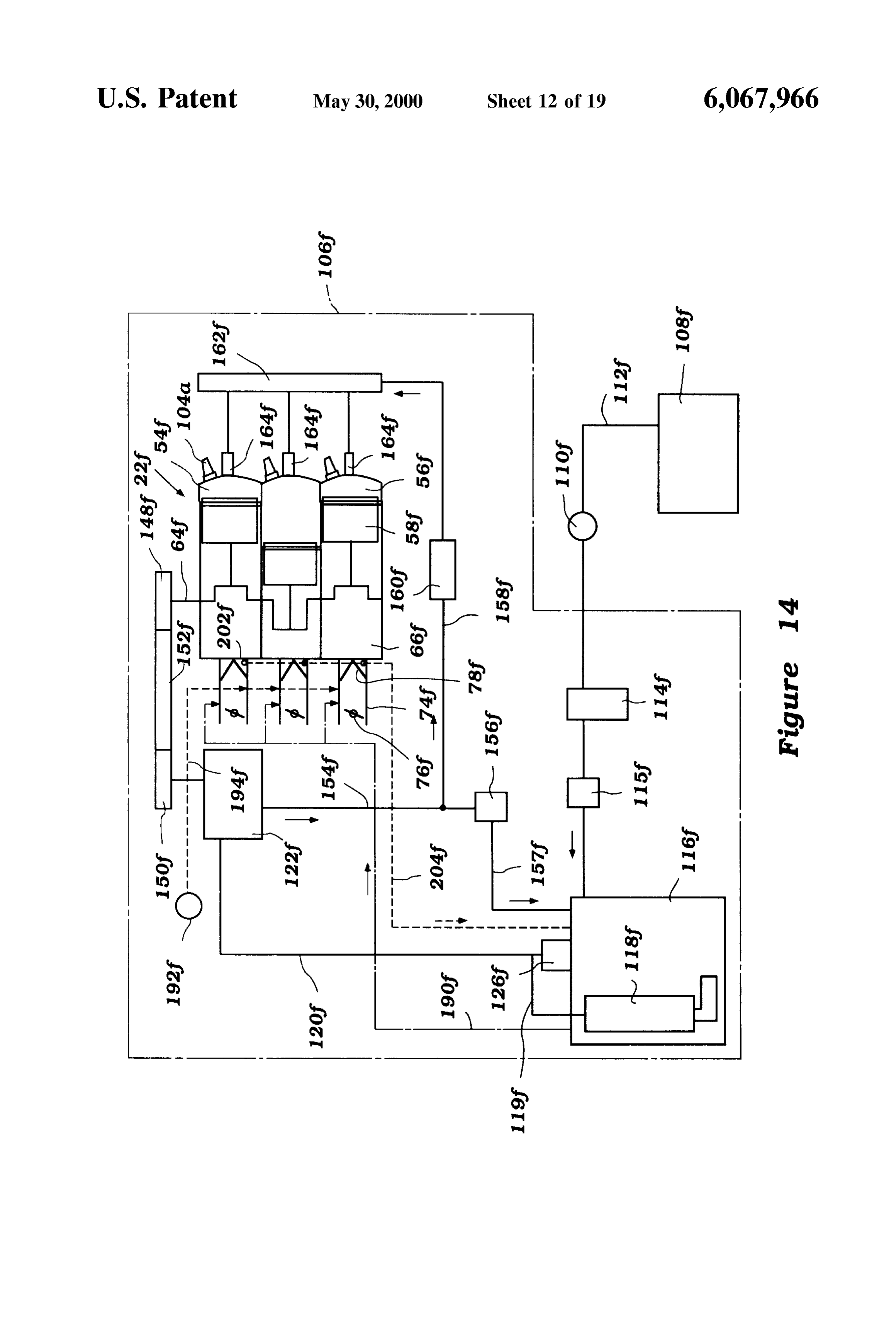
trated in FIG. 10. In the description and illustration of this Like the last embodiment, this embodiment has the embodiment, Similar parts have been given like reference 55 advantage that fuel cooling can be achieved with little numerals to those used in the above embodiments, except modification to the outboard and engine motor, in that most that a “c” designator has been added thereto. motorS already generally include water cooling Systems for This embodiment is similar to that illustrated in FIG. 8, their engine. In addition, in this embodiment, the fuel cooler that a fuel return is provided after the fuel rail 162c. In is incorporated into the vapor Separator, eliminating the need particular, fuel is delivered through the fuel line 154c from 60 for a separate Space consuming fuel cooler. the high pressure pump 122c through the filter 160c to the A fifth embodiment fuel Supply system 106f is illustrated fuel rail 162c. Fuel which is delivered to the rail, but not in FIGS. 14-19. In the description and illustrations of this delivered by the injectors 164c is selectively returned to the embodiment, Similar parts have been given like reference vapor separator 116c through a return line. A valve 156c is numerals to those used in the above embodiments, except preferably positioned at the end of the fuel rail 162c for 65 that an “f” designator has been added thereto. controlling the preSSure in the rail and the amount of fuel In this embodiment, the fuel which is delivered by the returned to the separator 116c. pre-pressurizing pump 118f is delivered through a line 119f
Page 25
which connects to the line 120f leading to the high pressure A sixth embodiment fuel Supply system 106g is illustrated pump 122f. As illustrated, the line 119f intersects the line in FIG. 20. In the description and illustration of this 120f between a pressure regulating check valve 126f and the embodiment, Similar parts have been given like reference pump 122f, the valve 126f arranged to route fuel back to the numerals to those used in the above embodiments, except Vapor Separator 116f in the event the fuel preSSure in the 5 that a “g designator has been added thereto. lines 119?, 120f becomes too high. In this embodiment, the engine 22g is of the “V'-type, This embodiment fuel Supply system 106f is similar to having a two cylinder heads 52g connected to the Single that illustrated in FIG. 8, except that a fuel cooler is not cylinder block 50g and cooperating therewith to define to provided and but instead a vapor relief line 190f extends banks of cylinders 54g. In the embodiment illustrated, each from the vapor separator 116f to the air intake passages 74f. bank contains three cylinderS 54g, but the banks may contain The vapor relief line 190f delivers fuel vapor to the air a greater or lesser number of cylinders as well known to passing through the passages 74f for combustion in the those of skill in the art.
engine 22f
In addition, a lubricant delivery System provides lubricant The fuel Supply system 106f is similar to that illustrated to the intake system and fuel Supply system 106f of the 15 in FIG. 10, except that a fuel cooler 124g is provided along engine 22f AS illustrated, lubricant is delivered from a a return line 157g instead of between the pre-pressurizing supply 192f through a supply line 194f to the intake passages and high pressure pumps as illustrated in FIG. 10. In 74f. addition, a fuel rail 162g is provided corresponding to each Referring to FIGS. 14-16, some of the lubricant which is cylinder bank, with each fuel rail 162g Supplying fuel to a delivered to the intake passages 74f does not flow directly to fuel injector 164g corresponding to each cylinder 54g of that the engine 22f but is instead routed to the vapor separator bank.
116f for mixing with the fuel. Fuel is delivered from the high pressure pump 122g As illustrated in FIG. 16, each reed valve 78f comprises through a high pressure line 158g. This line 158g splits or a valve member 196f positioned between an inner support bifurcates into a pair of feed lines 205g. Each feed line 205g 198f and an outer support 200f. The construction of these 25 leads to one of the fuel rails 162g. Fuel which is delivered types of valves 78f is well known. to the fuel rails 162g but not delivered by the injectors 164g A lubricant pool 202f is provided in at least one location selectively passes through the valve 156g and through the in each intake passage 74f. Preferably, a lubricant pool 202f return line 157g back to the vapor separator 116.g. is provided near a front end of each reed valve 78f and AS Stated above, a fuel cooler 124g is provided along this downstream of each reed valve 78f. The lubricant pools 202f return line 157g for cooling the fuel and reducing its vapor comprise channels or slots in the lower Surface of the intake content before it is returned to the vapor separator 116.g. Of passage 74f. course, this cooler fuel also reduces the temperature of the Each lubricant pool 202f is in communication with a fuel already in the Separator 116g. AS illustrated, an elec lubricant passage 204f Lubricant which is trapped in the tronic engine control unit or “ECU” 230g is used to control pools 178f is drawn through the passage 180f to the vapor is various of the engine components. The ECU 230g receives separator 116f, as illustrated in FIG. 14. The lubricant mixes information from various Sensors for use in controlling the with the fuel therein, and is delivered to the engine 22f engine 22g.
through the fuel Supply system 106f, including the fuel These Sensors include an engine temperature Sensor 232g, injectors 164f. This lubricant maintains the fuel injectors a crankshaft rotational position Sensor 234g, an intake air 164f free of corrosion. 40 temperature Sensor 236g, a throttle position Sensor 238g, an The arrangement of the vapor separator 116f of this ambient air pressure Sensor 240g, a crankcase chamber embodiment fuel Supply system 106f is illustrated in FIG. preSSure Sensor 244g, an engine vibration Sensor 246g, a 17. The vapor separator 116f comprises a body 206f defining motor trim position Sensor 248g, a motor height position a fuel chamber. The body 206f is comprised of a base 208f Sensor 250g, a cooling water temperature Sensor 252g, a having a lid 210f removably connected thereto. 45 transmission position or neutral Sensor 254g, a watercraft The fuel Supply line 112f is connected to a nipple 212f Speed Sensor 256g, a watercraft position Sensor 258g, an extending from the lid 210f. Likewise, the fuel line 119?, exhaust backpressure Sensor 260g, and an exhaust content or vapor line 190f, return line 157fand lubricant line or passage oxygen Sensor 262g. Other Sensors may also be provided. 204f are all connected to similar nipples 214f, 216f, 218?, Based on the various information received from the 220?, respectively. Like the embodiment vapor Separator 50 sensors, the ECU 230g controls the timing of the firing of the 116e illustrated in FIG. 13, this embodiment vapor separator Spark plugs 104g, and where the fuel injectors 164g include 116f preferably includes a coolantjacket 184f formed in the an electrically powered Solenoid and are not Solely pressure base 208f through which coolant passes for cooling the fuel operated, the opening and closing of the injectorS 164g. The therein. ECU 230g may be used to control a wide variety of other AS also illustrated in FIG. 17, the connection between the 55 components or engine functions, Such as the pre fuel line 119f and line 120f may comprise a “T”-fitting 222f pressurizing pump 118g (when electrically powered). These which is connected to a hose comprising the lines 119?, 120f, types of controls are well known to those of skill in the art and which is also connected to the valve 126f and may vary from that described above. FIGS. 18 and 19 best illustrate the layout of the fuel A seventh embodiment fuel Supply system 106h is illus supply system 106f components of this embodiment of the 60 trated in FIG. 21. In the description and illustration of this invention. AS illustrated, the components are primarily embodiment, Similar parts have been given like reference located in a Space along the Side of the engine 22f near the numerals to those used in the above embodiments, except air intake 72f. This arrangement permits the engine 22f to that an “h” designator has been added thereto. have a Small size and helps keep the fuel System cool. This embodiment fuel Supply system 106h is very similar Referring to FIG. 19, an idler pulley 224f is used to tension 65 to the last embodiment illustrated in FIG. 20. In this the drive belt 152f which drives the high pressure pump embodiment, the return line 157h extends from the control 150f or check valve 152h to the fuel line 120h and not the vapor
Page 26
Separator 116h. In this arrangement, the cooled fuel which is Separator and delivering Said fuel at a first preSSure above a returning through the return line 157h is mixed with the preSSure of Said fuel within Said vapor Separator to a high Smaller volume of fuel passing through the line 120h (i.e., preSSure pump, Said high preSSure pump pressurizing Said the fuel is returned to a point upstream of the vapor separator fuel to a pressure above Said first preSSure and delivering 116h along the fuel delivery path). This arrangement has the said fuel to a fuel rail through which fuel is delivered to said benefit of cooling the fuel being delivered through the fuel injector for delivery into Said combustion chamber, a passage 120h and the returned fuel, which is at a high return line extending from Said fuel rail to Said vapor preSSure, lessens the Volume of fuel which must be Separator for returning fuel delivered to Said fuel rail but not repumped by the pre-pressurizing pump 118h from the low delivered by Said fuel injector back to Said vapor separator, pressure fuel chamber of the separator 116h. Since less fuel an adjustment valve for regulating the flow of fuel through must be pumped, leSS fuel vapor is generated in the pumping Said return line and maintaining the fuel in Said fuel rail at proceSS by the pre-pressurizing pump 118h. high pressure, and further including a fuel cooler positioned An eighth embodiment fuel Supply system 106i is illus between Said adjustment valve and Said vapor Separator trated in FIG. 22. In the description and illustration of this along Said return line for cooling Said fuel passing there embodiment, Similar parts have been given like reference 15 through.
numerals to those used in the above embodiments, except 2. The fuel Supply System in accordance with claim 1, that an “i' designator has been added thereto. further including a relief valve for relieving fuel over a This embodiment fuel Supply system 106i is similar to predetermined high pressure from the fuel System between Said pre-pressurizing pump and Said high pressure pump that illustrated in FIG. 21 and described above. In accor dance with this embodiment, fuel which is returned through back to Said vapor Separator.
the return line 157i again passes through a fuel cooler 124i 3. The fuel Supply System in accordance with claim 1, and thereon back to the vapor Separator 116i. wherein Said pre-pressurizing pump is positioned within Said Fuel is pumped from the vapor separator 116i by the Vapor Separator.
4. The fuel Supply System in accordance with claim 1, pre-pressurizing pump 118i and delivered to the high pres 25 wherein sure pump 122i through a fuel line 120i. In the event the fuel Separator.Said fuel cooler comprises a water-cooled vapor preSSure in this line 120i exceeds a predetermined preSSure, 5. The fuel Supply System in accordance with claim 1, fuel is relieved through a check valve 126i through the fuel including a control operating Said pre-pressurizing pump at cooler 124i into the return line 157i.
In this arrangement, the fuel at high pressure which is a low speed when a Speed of Said engine is low. 6. The relieved and may contain a significant vapor content passes wherein at least fuel Supply System in accordance with claim 1, through the fuel cooler. a portion of the fuel Supplied by Said pre-pressurizing pump to Said high pressure pump is
In the embodiments of the invention described above, it returned through a line back to said vapor separator. should be understood that the various fuel, lubricant and 7. The fuel Supply System in accordance with claim 1, Vapor lines may comprise any number of materials as known 35 wherein at least a portion of the fuel Supplied by Said to those skilled in the art. For example, the fuel lines may pre-pressurizing pump passes through a fuel cooler and is comprise rubber hose, metal piping, and even one or more returned to Said vapor separator.
passages formed within a portion of the engine Such as the 8. A fuel Supply System for Supplying fuel from a fuel cylinder block. Source to an engine powering an outboard motor, the engine In the embodiments of the fuel system described above, it 40 having at least one combustion chamber, Said fuel Supply should be understood that the pre-pressurizing pump 188a-h System comprising a vapor Separator to which fuel is deliv may be driven or operated at a speed which is proportional ered from the fuel Source for Separation of vapor from the to engine Speed. For example, when the engine Speed is low, fuel, a pre-pressurizing pump for pressurizing fuel from the the pre-pressurizing pump 188a–h is preferably operated at Separator and delivering Said fuel at a first preSSure above a a low Speed, Since the fuel requirements of the engine 22a-h 45 preSSure of Said fuel within Said vapor Separator to a high are reduced. This may be accomplished through an elec preSSure pump, Said high preSSure pump pressurizing Said tronic control when the pre-pressurizing pump 118a–h is of fuel to a pressure above Said first preSSure and delivering the electric type. AS disclosed above, the high-pressure said fuel to a fuel rail through which fuel is delivered to said pump 122a-h is operated at a speed proportional to the fuel injector for delivery into Said combustion chamber, a engine Speed Since it is driven by the crankshaft of the 50 return line extending from Said fuel rail to a point along Said engine 22a-h. fuel System after Said pre-pressurizing pump for returning Those of skill in the art will appreciate that certain fuel delivered to said fuel rail but not delivered by said fuel features of one or more embodiments of each fuel Supply injector, an adjustment valve for regulating the flow of fuel system 106a-h described above may be used or incorporated through Said return line and maintaining the fuel in Said fuel into other embodiment fuel Supply Systems. 55 rail at high pressure, and further including a fuel cooler Of course, the foregoing description is that of preferred positioned along Said return line for cooling Said fuel embodiments of the invention, and various changes and passing therethrough.
modifications may be made without departing from the Spirit 9. The fuel supply system in accordance with claim 8, and Scope of the invention, as defined by the appended wherein Said pre-pressurizing pump is operated at a low claims. 60 Speed if a speed of Said engine is low. What is claimed is: 10. The fuel Supply system in accordance with claim 8, 1. A fuel Supply System for Supplying fuel from a fuel wherein Said valve is pressure operated and positioned along Source to an engine powering an outboard motor, the engine Said Second fuel line.
having at least one combustion chamber, Said fuel Supply 11. The fuel supply system in accordance with claim 8, System comprising a vapor Separator to which fuel is deliv 65 wherein said second fuel line leads to a first end of said fuel ered from the fuel Source for Separation of vapor from the rail and Said valve is pressure operated at positioned at a fuel, a pre-pressurizing pump for pressurizing fuel from the Second end of Said fuel rail.
Page 27
12. The fuel Supply System in accordance with claim 8, pre-pressurizing pump to Said high pressure pump is further including a fuel cooler positioned along Said fuel returned through a line back to Said vapor Separator. Supply System between said vapor separator and Said Second 15. The fuel Supply system in accordance with claim 8, pump. wherein at least a portion of the fuel Supplied by Said 13. The fuel Supply system in accordance with claim 8, pre-pressurizing pump passes through a fuel cooler and is further including a fuel filter positioned along Said fuel returned to Said vapor separator. Supply System between Said Second pump and Said fuel injector.
14. The fuel Supply system in accordance with claim 8, wherein at least a portion of the fuel Supplied by Said
Provenance
- Collection
- Cited prior art
- Original PDF
- patentimages.storage.googleapis.com →
- Filed
- 1998-06-16
- Pages
- 27
- Method
- pdftotext (the PDF's own text layer) + pdftoppm 300dpi page scans
- Source
- Google Patents bibliographic record
- Granted
- 2000-05-30
- Inventors
- Chitoshi Saito; Masahiko Kato; Masafumi Sougawa; Sanshin Kogyo KK
- Transcribed from
- patentimages.storage.googleapis.com →