patent · US6051776
Light condensing-type solar generator system
18 April 2000
Page 1 — bibliographic record
United States Patent (19) 11 Patent Number: 6,051,776 Kimata et al. (45) Date of Patent: Apr. 18, 2000 54) LIGHT CONDENSING-TYPE SOLAR 5,707,458 1/1998 Nagashima et al. .................... 136/246 GENERATOR SYSTEM FOREIGN PATENT DOCUMENTS 75 Inventors: Ryuichi Kimata; Noboru Kawaguchi, 7-231111 8/1995 Japan. both of Wako, Japan
Primary Examiner Nam Nguyen 73 Assignee: Honda Giken Kogyo Kabushiki Assistant Examiner Michael C. Miggins Kaisha, Tokyo, Japan Attorney, Agent, or Firm-Arent Fox Kintner; Plotkin & Kahn PLLC 21 Appl. No.: 09/265,572 57 ABSTRACT 22 Filed: Mar 10, 1999 A Solar battery cell of a back-electrode type is used to 30 Foreign Application Priority Data enhance the photo-electric efficiency in which the electrical connecting Structure for the Solar battery cell is simplified,
Mar. 11, 1998 JP Japan .................................. 10-0598.93 and the deterioration of connected portions can be pre 51 Int. Cl." .......................... H01L 31/052; H01L 31/05 vented. The Solar battery cell of a back-electrode type 52 U.S. Cl. ........................... 136/246; 136/256; 126/624 having Second electrodes on the back thereof, are placed on 58 Field of Search ..................................... 136/259, 246, and fixed to a board having first electrodes on its Surface, So that the first electrodes and the Second electrodes are elec 136/248, 256, 257; 250/239; 126/624 trically connected to each other. Output terminals are con nected to the first electrodes on the board outside of and to
the Side of the Solar battery cell, by Soldering. A truncated
as a light receiving end face is placed on and fixed to a 3.368,078 2/1968 Flint et al. .............................. 250/216 Surface of the Solar battery cell with the light receiving end 4,830,678 5/1989 Todorof et al. ......................... 136/259 face disposed in the vicinity of the focal point of the lens.
5,118,361 6/1992 Fraas et al. ............................. 136/246 5,460,659 10/1995 Krut ........................................ 136/246 6 Claims, 5 Drawing Sheets
Page 2
Drawing sheet — no readable text.
Page 3
Drawing sheet — no readable text.
Page 4
Drawing sheet — no readable text.
Page 5
Drawing sheet — no readable text.
Page 6
Drawing sheet — no readable text.
Page 7
LIGHT CONDENSING-TYPE SOLAR and fixed to the board, so that the first electrodes and the GENERATOR SYSTEM Second electrodes are electrically connected to each other; and the output terminals are connected to the first electrodes
BACKGROUND OF THE INVENTION on the board outside of and to the side of the Solar battery 1. Field of the Invention cell by brazing. A truncated conical light guide which has a larger diameter-end face Serving as a light receiving end
The present invention relates to a light condensing-type face, is placed on and fixed to a Surface of the Solar battery Solar generator System for condensing Sun rays into a Solar battery cell, to produce electric power by photo-electrical cell of with the light receiving end face disposed in the vicinity the focal point of the lens.
conversion.
With the above arrangement, the output terminals, which 2. Description of the Prior Art are separate from the board, are connected to the first A light condensing-type Solar generator System for con electrodes formed on the surface of the board by brazing and densing Sun rays into a Solar battery cell with a lens to therefore, the electrical connecting Structure is simple and effectively utilize the capability of the Solar battery cell, to moreover, the connecting proceSS is simplified. In addition, reduce generating cost is already known, for example, from 15 the Sun rays condensed by the lens are guided to the Surface Japanese Patent Application Laid-Open No. 7-231111. of the Solar battery cell by the light truncated conical guide The light condensing-type Solar generator System dis and hence, the focused Sun rays are not applied to the closed in the above Japanese Patent Application Laid-Open connected portions of the first electrodes and the output No. 7-231111 is of a structure wherein a small sized Solar terminals, whereby the deterioration of the connected por battery cell with one side as Small as 2 mm, is connected to tions due to the application of the Sun rays, is prevented. an IC type carrier Such as a dual in-line package or the like. The junctions of the output terminals to the first electrodes The carrier is mounted So that it is inset into a printed circuit are formed into a comb tooth shape. With such an board Such as a through-hole board, whereby a plurality of arrangement, when the output terminals are connected to the Solar battery cells are electrically connected to one another. first electrodes by brazing, the unnecessary diffusion of heat However, the electrical connecting arrangement of the 25 can be prevented, to thus carry out the connection operation known Solar generator System is difficult to apply where the easily and reliably. Moreover, it is possible to moderate the Size of the Solar battery cell is increased for obtaining large StreSS applied to the connected portions after completion of electric power. When a large-sized Solar battery cell is used, the connection.
a Soldering or brazing structure must be relied on. However, BRIEF DESCRIPTION OF THE DRAWINGS when the magnification of condensation of light rays to the
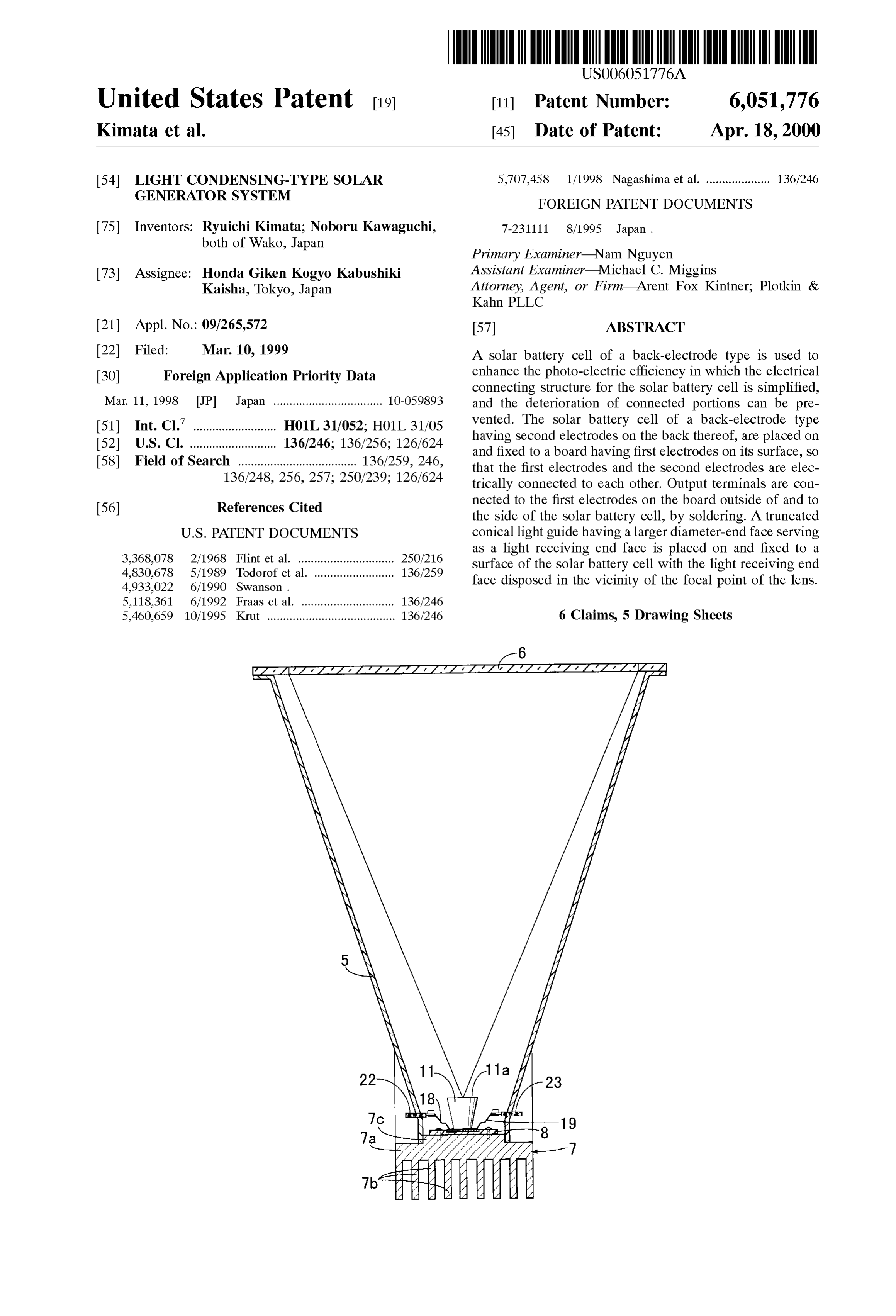
Solar battery cell exceeds 100, the deterioration of connected FIG. 1 is a vertical Sectional view of a light condensing portions provided by Soldering or the like is hastened, if the type Solar generator System according to an embodiment of converged light rays are applied to the connected portions. the present invention.
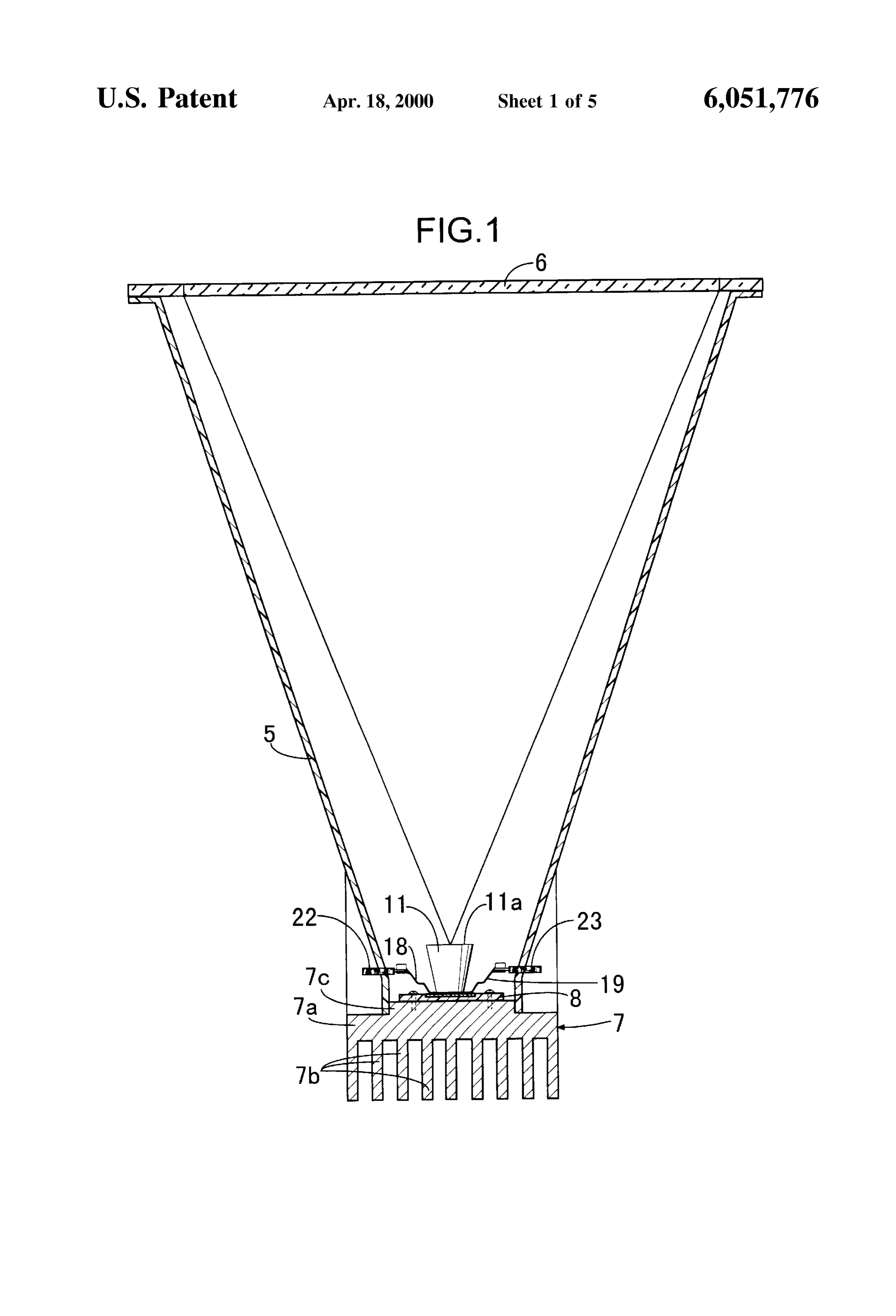
On the other hand, an attempt is made (in U.S. Pat. No. 35 FIG. 2 is an enlarged view of an essential portion shown 4,933,022) to use a solar battery cell of a back-electrode type in FIG. 1.
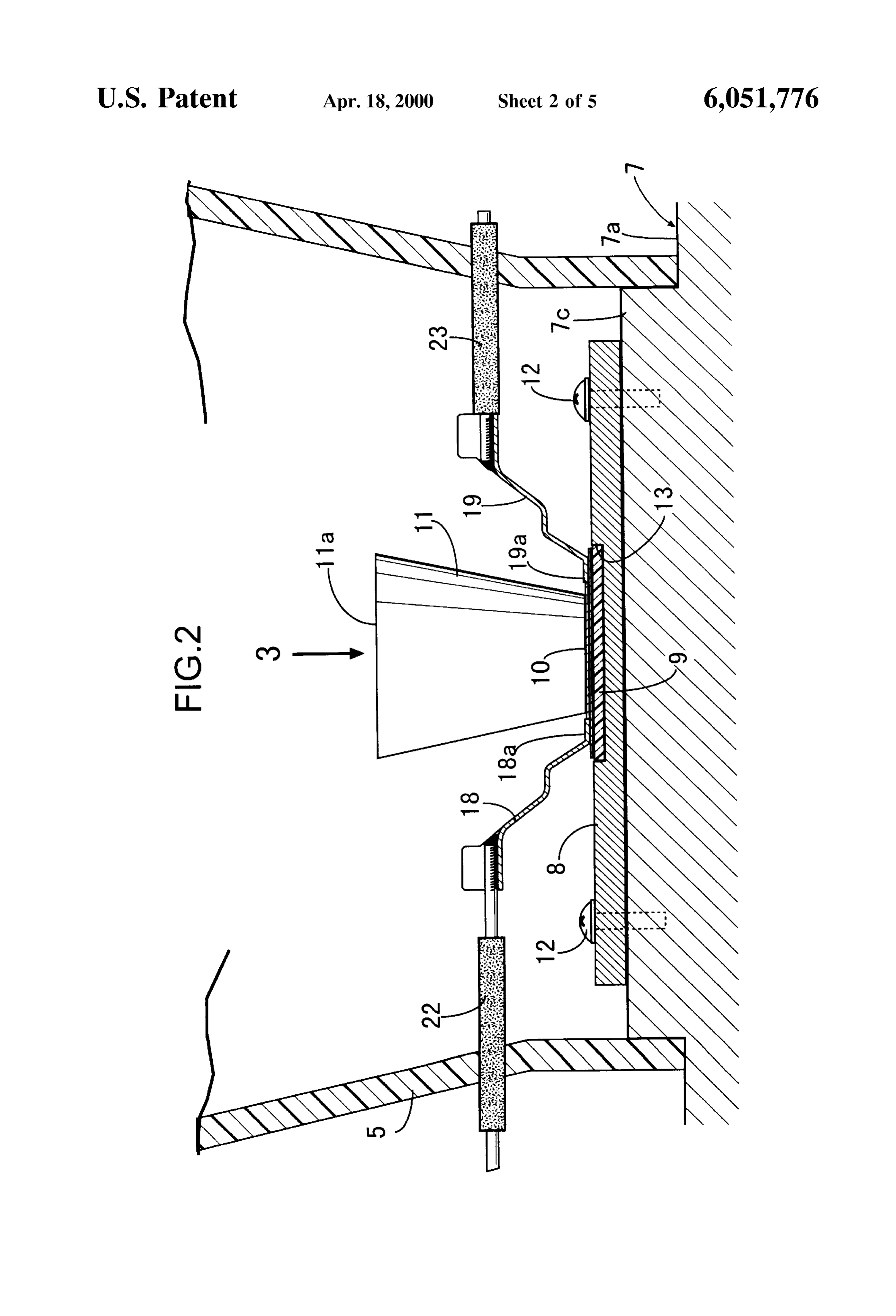
having an electrode on the back rather than on the Surface to which Sun rays are applied, for enhancing the photo in FIG. 3 is a plan view taken in a direction of an arrow 3
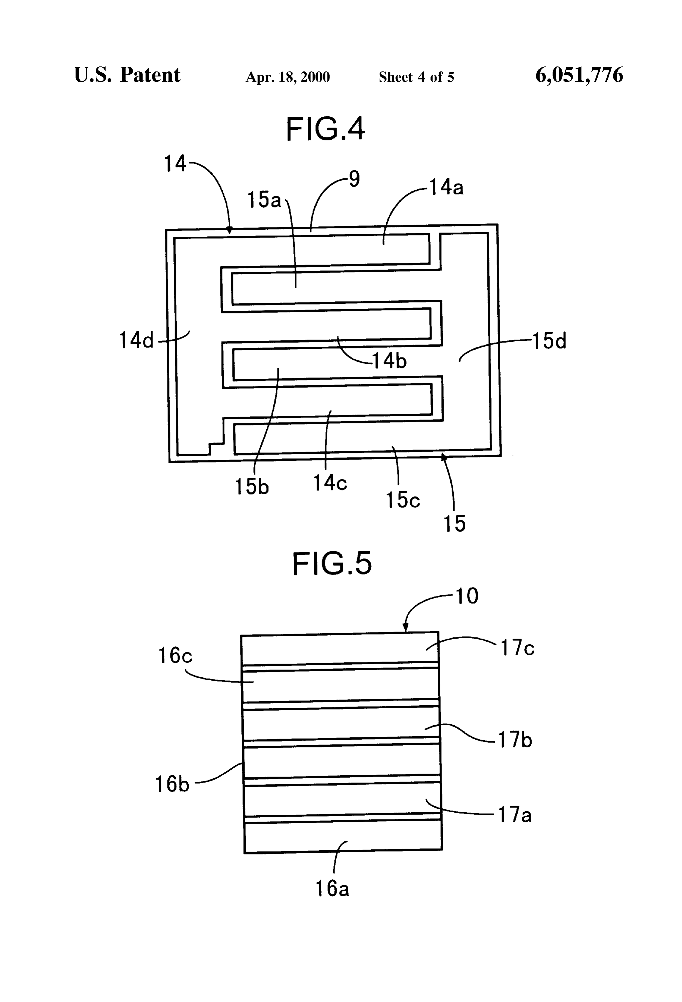
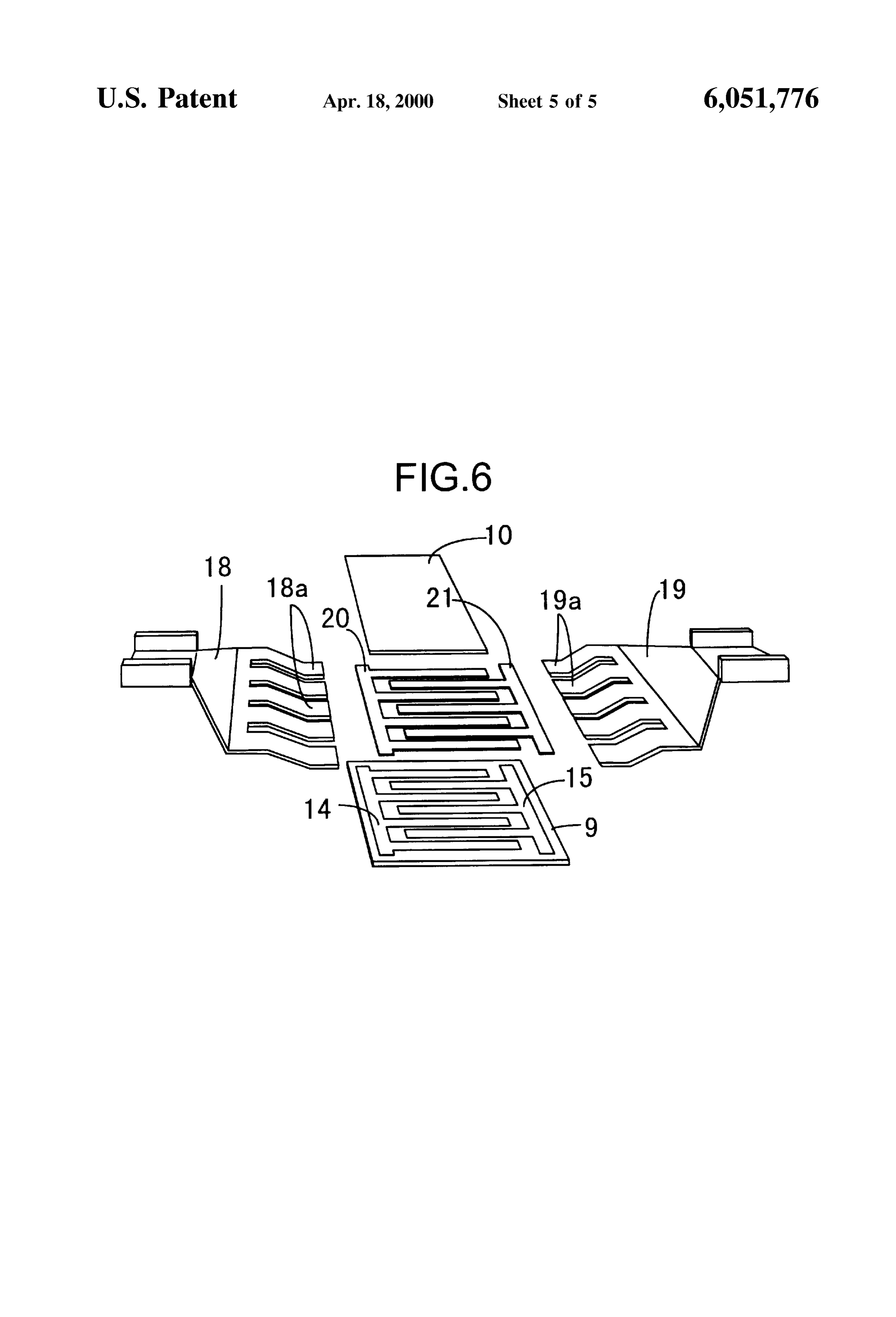
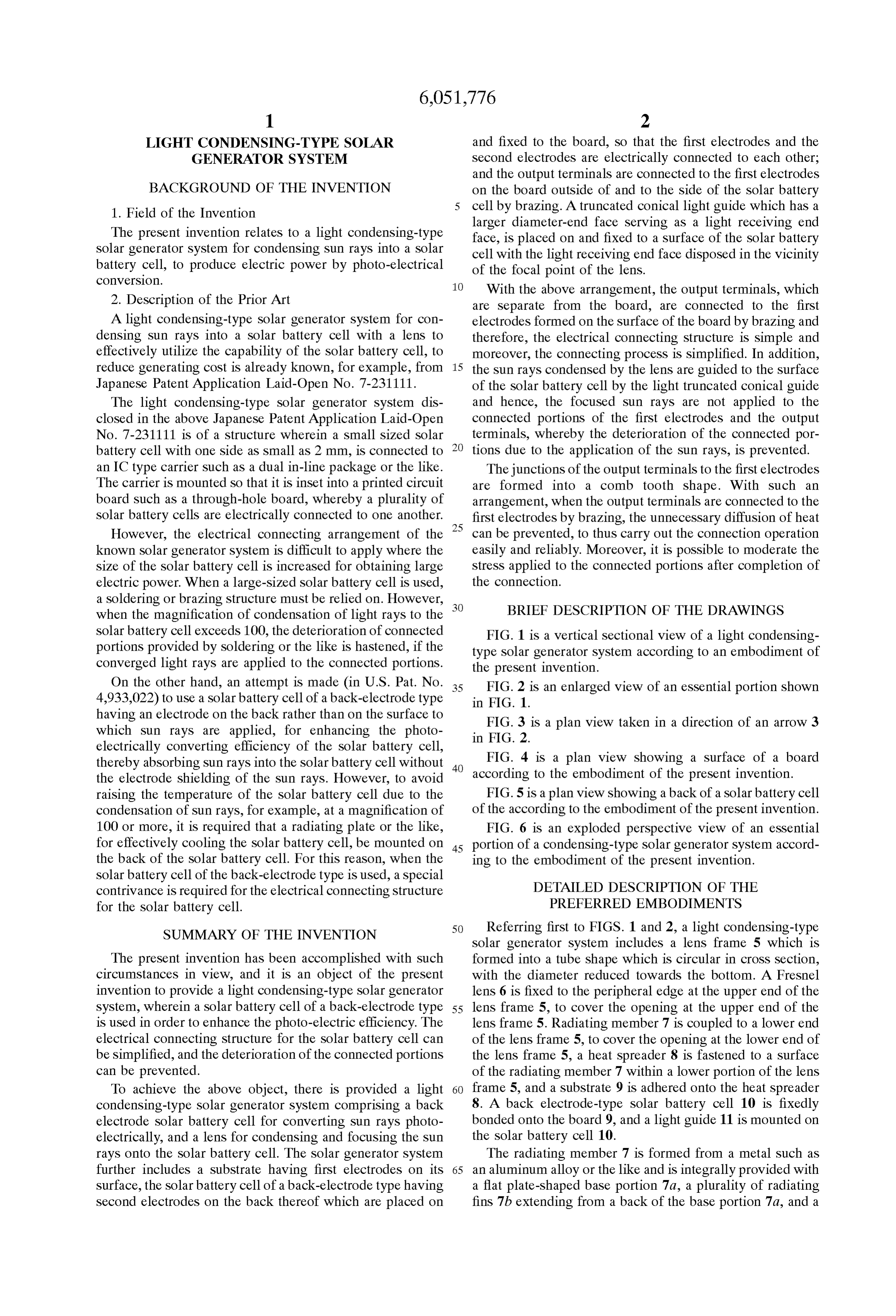
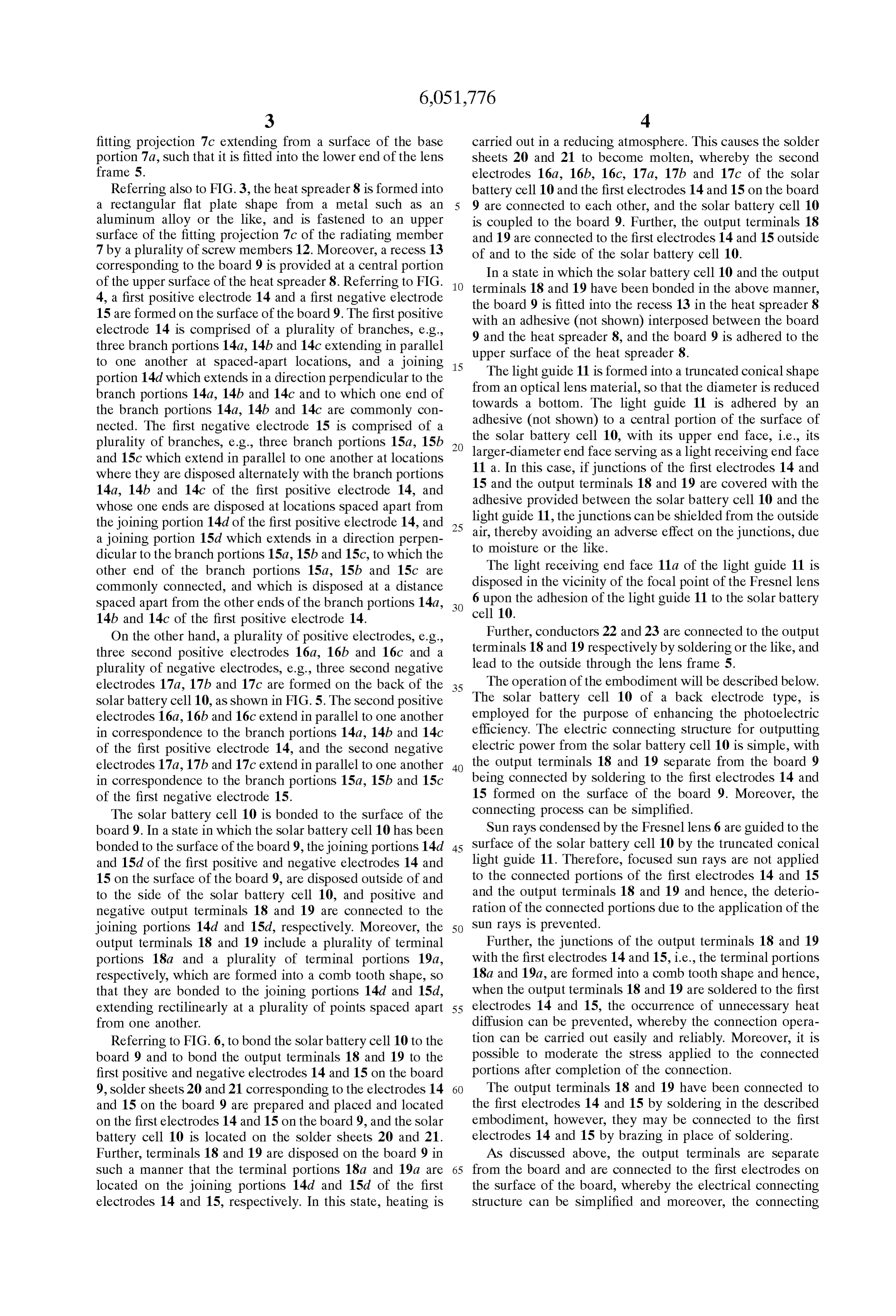
electrically converting efficiency of the Solar battery cell, thereby absorbing Sun rays into the Solar battery cell without 40 FIG. 4 is a plan view showing a surface of a board the electrode Shielding of the Sun rayS. However, to avoid according to the embodiment of the present invention. raising the temperature of the Solar battery cell due to the FIG. 5 is a plan view showing a back of a solar battery cell condensation of Sun rays, for example, at a magnification of of the according to the embodiment of the present invention. 100 or more, it is required that a radiating plate or the like, FIG. 6 is an exploded perspective view of an essential for effectively cooling the Solar battery cell, be mounted on 45 portion of a condensing-type Solar generator System accord the back of the Solar battery cell. For this reason, when the ing to the embodiment of the present invention. Solar battery cell of the back-electrode type is used, a special contrivance is required for the electrical connecting structure DETAILED DESCRIPTION OF THE for the solar battery cell. PREFERRED EMBODIMENTS
SUMMARY OF THE INVENTION 50 Referring first to FIGS. 1 and 2, a light condensing-type Solar generator System includes a lens frame 5 which is
The present invention has been accomplished with Such formed into a tube shape which is circular in croSS Section, circumstances in View, and it is an object of the present with the diameter reduced towards the bottom. A Fresnel invention to provide a light condensing-type Solar generator lens 6 is fixed to the peripheral edge at the upper end of the System, wherein a Solar battery cell of a back-electrode type 55 lens frame 5, to cover the opening at the upper end of the is used in order to enhance the photo-electric efficiency. The lens frame 5. Radiating member 7 is coupled to a lower end electrical connecting Structure for the Solar battery cell can of the lens frame 5, to cover the opening at the lower end of be simplified, and the deterioration of the connected portions the lens frame 5, a heat Spreader 8 is fastened to a Surface can be prevented. of the radiating member 7 within a lower portion of the lens To achieve the above object, there is provided a light 60 frame 5, and a substrate 9 is adhered onto the heat spreader condensing-type Solar generator System comprising a back 8. A back electrode-type solar battery cell 10 is fixedly electrode Solar battery cell for converting Sun rays photo bonded onto the board 9, and a light guide 11 is mounted on electrically, and a lens for condensing and focusing the Sun the Solar battery cell 10.
rays onto the Solar battery cell. The Solar generator System The radiating member 7 is formed from a metal such as further includes a Substrate having first electrodes on its 65 an aluminum alloy or the like and is integrally provided with Surface, the Solar battery cell of a back-electrode type having a flat plate-shaped base portion 7a, a plurality of radiating Second electrodes on the back thereof which are placed on fins 7b extending from a back of the base portion 7a, and a
Page 8
fitting projection 7c extending from a Surface of the base carried out in a reducing atmosphere. This causes the Solder portion 7a, such that it is fitted into the lower end of the lens sheets 20 and 21 to become molten, whereby the second frame 5. electrodes 16a, 16b, 16c, 17a, 17b and 17c of the Solar Referring also to FIG.3, the heat spreader 8 is formed into battery cell 10 and the first electrodes 14 and 15 on the board a rectangular flat plate shape from a metal Such as an 9 are connected to each other, and the Solar battery cell 10 aluminum alloy or the like, and is fastened to an upper is coupled to the board 9. Further, the output terminals 18 Surface of the fitting projection 7c of the radiating member and 19 are connected to the first electrodes 14 and 15 outside 7 by a plurality of screw members 12. Moreover, a recess 13 of and to the side of the Solar battery cell 10. corresponding to the board 9 is provided at a central portion In a state in which the Solar battery cell 10 and the output of the upper surface of the heat spreader 8. Referring to FIG. terminals 4, a first positive electrode 14 and a first negative electrode the board 18 9 and 19 have been bonded in the above manner, is fitted into the recess 13 in the heat spreader 8 15 are formed on the surface of the board 9. The first positive with an adhesive (not shown) interposed between the board electrode 14 is comprised of a plurality of branches, e.g., 9 and the heat spreader three branch portions 14a, 14b and 14c extending in parallel upper Surface of the heat8, spreader and the board 9 is adhered to the
to one another at Spaced-apart locations, and a joining 15 portion 14d which extends in a direction perpendicular to the The light guide 11 is formed into a truncated conical shape branch portions 14a, 14b and 14c and to which one end of towards a bottom. The light guidethe11diameter from an optical lens material, So that is reduced is adhered by an the branch portions 14a, 14b and 14c are commonly con nected. The first negative electrode 15 is comprised of a adhesive (not shown) to a central portion of the Surface of plurality of branches, e.g., three branch portions 15a, 15b the Solar battery cell 10, with its upper end face, i.e., its larger-diameter end face Serving as a light receiving end face and 15c which extend in parallel to one another at locations where they are disposed alternately with the branch portions 11 a. In this case, if junctions of the first electrodes 14 and 14a, 14b and 14c of the first positive electrode 14, and 15 and the output terminals 18 and 19 are covered with the adhesive provided between the solar battery cell 10 and the whose one ends are disposed at locations Spaced apart from light guide 11, the junctions can be shielded from the outside the joining portion 14d of the first positive electrode 14, and 25 air, thereby a joining portion 15d which extends in a direction perpen to moisture avoiding or the like.
an adverse effect on the junctions, due dicular to the branch portions 15a, 15b and 15c, to which the other end of the branch portions 15a, 15b and 15c are The light receiving end face 11a of the light guide 11 is commonly connected, and which is disposed at a distance disposed in the vicinity of the focal point of the Fresnel lens Spaced apart from the other ends of the branch portions 14a, cell 6 upon the adhesion of the light guide 11 to the solar battery 14b and 14c of the first positive electrode 14. 10.
On the other hand, a plurality of positive electrodes, e.g., Further, conductorS 22 and 23 are connected to the output three second positive electrodes 16a, 16b and 16c and a terminals 18 and 19 respectively by soldering or the like, and plurality of negative electrodes, e.g., three Second negative lead to the outside through the lens frame 5. electrodes 17a, 17b and 17c are formed on the back of the 35 The operation of the embodiment will be described below. Solar battery cell 10, as shown in FIG. 5. The second positive The Solar battery cell 10 of a back electrode type, is electrodes 16a, 16b and 16c extend in parallel to one another employed for the purpose of enhancing the photoelectric in correspondence to the branch portions 14a, 14b and 14c efficiency. The electric connecting structure for outputting of the first positive electrode 14, and the Second negative electric power from the Solar battery cell 10 is simple, with electrodes 17a, 17b and 17c extend in parallel to one another 40 the output terminals 18 and 19 Separate from the board 9 in correspondence to the branch portions 15a, 15b and 15c being connected by Soldering to the first electrodes 14 and of the first negative electrode 15. 15 formed on the Surface of the board 9. Moreover, the The solar battery cell 10 is bonded to the surface of the connecting process can be simplified.
board 9. In a state in which the Solar battery cell 10 has been Sun rays condensed by the Fresnel lens 6 are guided to the bonded to the surface of the board 9, the joining portions 14d 45 surface of the Solar battery cell 10 by the truncated conical and 15d of the first positive and negative electrodes 14 and light guide 11. Therefore, focused Sun rays are not applied 15 on the surface of the board 9, are disposed outside of and to the connected portions of the first electrodes 14 and 15 to the side of the Solar battery cell 10, and positive and and the output terminals 18 and 19 and hence, the deterio negative output terminals 18 and 19 are connected to the ration of the connected portions due to the application of the joining portions 14d and 15d, respectively. Moreover, the 50 Sun rays is prevented.
output terminals 18 and 19 include a plurality of terminal Further, the junctions of the output terminals 18 and 19 portions 18a and a plurality of terminal portions 19a, with the first electrodes 14 and 15, i.e., the terminal portions respectively, which are formed into a comb tooth shape, So 18a and 19a, are formed into a comb tooth shape and hence, that they are bonded to the joining portions 14d and 15d, when the output terminals 18 and 19 are soldered to the first extending rectilinearly at a plurality of points Spaced apart 55 electrodes 14 and 15, the occurrence of unnecessary heat from one another. diffusion can be prevented, whereby the connection opera Referring to FIG. 6, to bond the Solar battery cell 10 to the tion can be carried out easily and reliably. Moreover, it is board 9 and to bond the output terminals 18 and 19 to the possible to moderate the StreSS applied to the connected first positive and negative electrodes 14 and 15 on the board portions after completion of the connection. 9, solder sheets 20 and 21 corresponding to the electrodes 14 60 The output terminals 18 and 19 have been connected to and 15 on the board 9 are prepared and placed and located the first electrodes 14 and 15 by soldering in the described on the first electrodes 14 and 15 on the board 9, and the Solar embodiment, however, they may be connected to the first battery cell 10 is located on the solder sheets 20 and 21. electrodes 14 and 15 by brazing in place of soldering. Further, terminals 18 and 19 are disposed on the board 9 in AS discussed above, the output terminals are separate such a manner that the terminal portions 18a and 19a are 65 from the board and are connected to the first electrodes on located on the joining portions 14d and 15d of the first the Surface of the board, whereby the electrical connecting electrodes 14 and 15, respectively. In this State, heating is Structure can be simplified and moreover, the connecting
Page 9
S 6 proceSS can be simplified. In addition, the focused Sun rays a light guide having a truncated conical shape and having a are not applied to the connected portions of the first elec larger diameter end face Serving as a light receiving end trodes and the output terminals, whereby the deterioration of face, wherein a focal point of Said lens is disposed around the connected portions due to the application of the Sun rayS, Said light receiving end face of Said light guide, wherein Said can be prevented. light guide is fixed to a Surface of Said Solar battery cell, and When the output terminals are connected to the first wherein Said output terminals include a plurality of comb electrodes by brazing, the unnecessary diffusion of heat can tooth portions, Said comb-tooth portions being connected to be prevented and the connecting operation can be easily and Said first electrodes.
reliably performed, and after completion of the connection, 2. A light condensing Solar generator according to claim the StreSS applied to the connected portions can be moder 1, wherein Said focal point of Said lens is disposed in the ated. large diameter end face of Said light guide. Although the embodiment of the present invention has 3. A light condensing Solar generator System according to been described in detail, it will be understood that the any one of claims 1 and 2, wherein Said light guide is formed present invention is not limited to the above-described 15 from 4.
an optical lens material.
A light condensing Solar generator System according to embodiment, and various modifications may be made with out departing from the Subject matter of the present inven claim 1, wherein Said first and Second electrodes each tion. comprise a plurality of branch portions with distances ther What is claimed is: ebetween and joining portions for connecting Said branch 1. A light condensing Solar generator System comprising portions.
a back electrode Solar battery cell for converting Sun rays 5. A light condensing Solar generator System according to photo-electrically, a lens for condensing and focusing the claim 1, wherein Said first and Second electrodes each Sun rays onto Said Solar battery cell, a Substrate having first comprise a plurality of branch portions with distances ther electrodes on the Surface thereof, said Solar battery cell ebetween and joining portions for connecting Said branch having Second electrodes on a back thereof and being free of 25 portions.
6. A light condensing Solar generator System according to electrodes on a front Surface thereof, wherein Said Solar battery cell is directly fixed to said substrate by brazing such claim 5, wherein said comb-tooth portions of each of said that Said first electrodes and Said Second electrodes are output terminals are connected to Said joining portions of electrically connected to each other, output terminals con Said first electrodes, respectively.
nected to Said first electrodes on Said Substrate by brazing at locations outside of and to the Side of Said Solar battery cell,
Provenance
- Collection
- Cited prior art
- Original PDF
- patentimages.storage.googleapis.com →
- Filed
- 1999-03-10
- Pages
- 9
- Method
- pdftotext (the PDF's own text layer) + pdftoppm 300dpi page scans
- Source
- Google Patents bibliographic record
- Granted
- 2000-04-18
- Inventors
- Ryuichi Kimata; Noboru Kawaguchi; Honda Motor Co Ltd
- Transcribed from
- patentimages.storage.googleapis.com →