patent · US6044831
Fuel vapor feed controlling apparatus for lean burn type internal combustion engine
4 April 2000
Page 1 — bibliographic record
United States Patent (19) 11 Patent Number: 6,044,831 Takagi et al. (45) Date of Patent: Apr. 4, 2000 54 FUEL VAPOR FEED CONTROLLING 5,613,481 3/1997 Kitagawa et al. ...................... 123/698 APPARATUS FOR LEAN BURN TYPE 5,765,372 6/1998 Mitobe et al. .......................... 123/385 INTERNAL COMBUSTION ENGINE FOREIGN PATENT DOCUMENTS 75 Inventors: Naoya Takagi; Toshimi Murai, both of 44 02588 A1 8/1994 Germany. Susono; Yoshihiko Hyodo, Gotenba; 19538 786
Zenichiro Mashiki, Toyota; Tetsuji A1 4/1997 Germany.
Nagata, Kariya, all of Japan 4-194354 7/1992 Japan.
O O 5-71430 3/1993 Japan.
73 ASSignee: Eye desha Kabushiki Kaisha, 5-223017 8/1993 Japan. Oyola, Japan 6-137190 5/1994 Japan.
21 Appl. No.: 08/990,466 6-200794 7/1994 Japan.
O O Primary Examiner Erick R. Solis 30 Foreign Application Priority Data Attorney, Agent, or Firm-Oliff & Berridge, PLC Dec. 16, 1996 JP Japan .................................... 8-335.738
Dec. 19, 1996 JP Japan ... 07: 57 ABSTRACT Dec. 19, 1996 JP Japan ... 8-3397.87 A fuel vapor feed controlling apparatus of a lean burn Ny. . E. E. - - - - 36 internal combustion engine Suppresses either one of a rich N. 21, 1997 E. E. - - - - 6321st misfire or a Surge when fuel Vapor is fed into the engine. A • 4 u-2 Pall . . . . . . . . . . . . . . . . . . . . . . . . . . . . . . . . . . . . purge controlling unit controls an amount of fuel vapor fed (51) Int. Cl." ...................................................... F20D 41/04 from a fuel reservoir to the engine in response to an 52 U.S. Cl. ............ 123/698; 123/520 operational condition of the engine. A first compensation 58 Field of Search ..................................... 123/520, 698, unit compensates the amount of fuel vapor Such that an 123/295 engine revolution Speed of the engine may be identical with a target revolution Speed. The purge controlling unit per 56) References Cited forms a purge control based on a compensation value compensated by the first compensation unit.
5,438,967 8/1995 Ito . 22 Claims, 57 Drawing Sheets
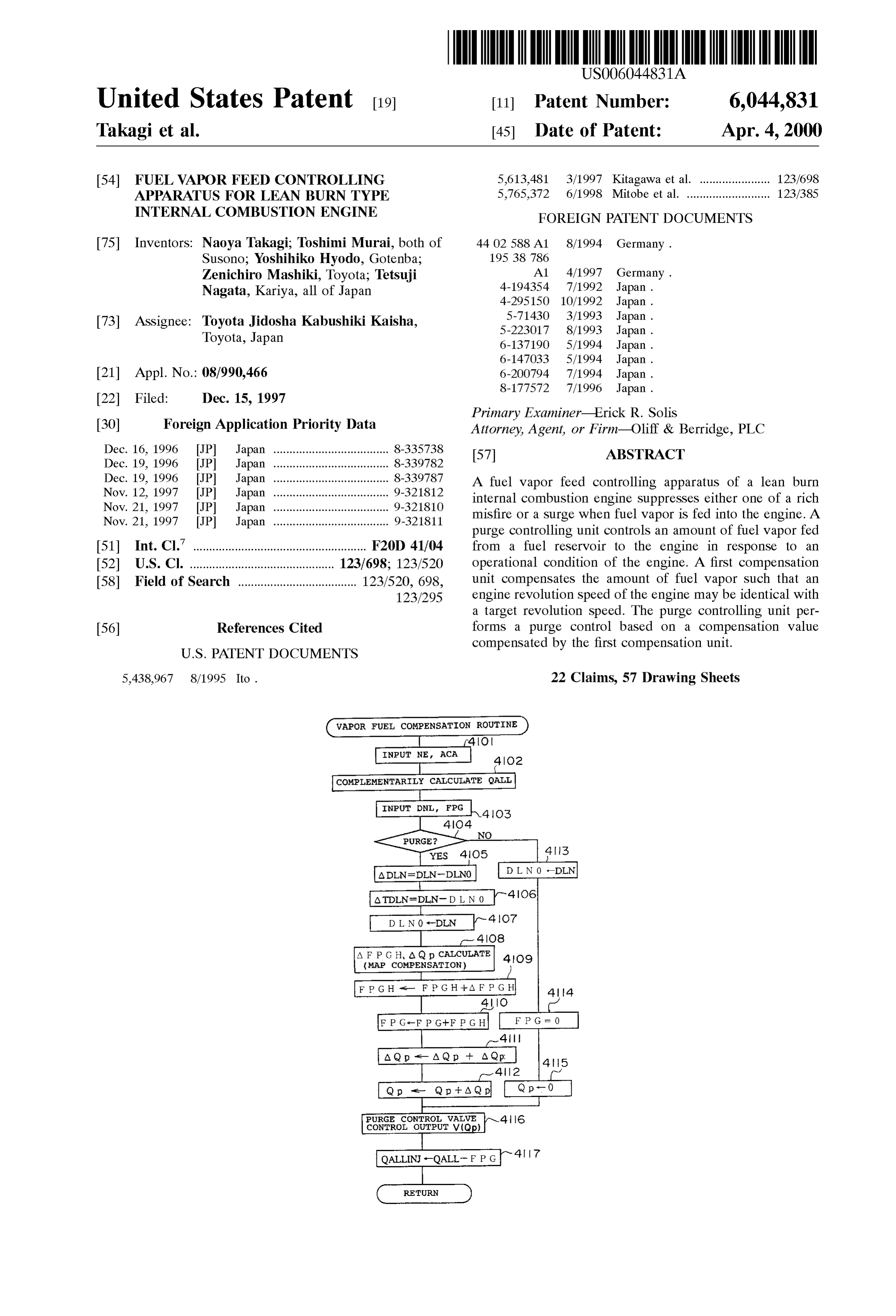
WAPOR FUEL COMPENSATION ROUTINE
INPUT NE ACA
COMPLEMENTARILY CALCULATE QALL
INPUT DNL, FPG
segreeds YES
A F P G H A Qp CALCULATE 4O9
(MAP compenSATION)
conTROL OUTPUT wop
RETURN
Page 2
Drawing sheet — no readable text.
Page 3
Drawing sheet — no readable text.
Page 4
Drawing sheet — no readable text.
Page 5
Drawing sheet — no readable text.
Page 6
Drawing sheet — no readable text.
Page 7
VAPOR FUEL COMPENSATION ROUTINE
INPUT NE ACA-6
COMPLEMENTALLY CALCULATE QALLh-7
YES
JUDGE COMBUSTION CONDITION 9
SET COMPENSATION COEFFICIENT O
YES
ppg - d. pc-1 kDP c tyEs so
Page 8
Drawing sheet — no readable text.
Page 9
Drawing sheet — no readable text.
Page 10
Drawing sheet — no readable text.
Page 11
Drawing sheet — no readable text.
Page 12
Drawing sheet — no readable text.
Page 13
Drawing sheet — no readable text.
Page 14
Drawing sheet — no readable text.
Page 15
Drawing sheet — no readable text.
Page 16
Drawing sheet — no readable text.
Page 17
Drawing sheet — no readable text.
Page 18
DPG
FPG
COMBUSTION MODE
COMBUSTION MODE A : COMBUSTION MODE B
FIG 21
DEGREE OF
CHANGE
DPG
DEGREE OF .
CHANGE
FPG
COMBUSTION MODE------
coMBUSTION MODE A : COMBUSTION MODE B
Page 19
Drawing sheet — no readable text.
Page 20
Drawing sheet — no readable text.
Page 21
Drawing sheet — no readable text.
Page 22
WAPOR FUEL COMPENSATION ROUTINE
COMPLEMENTARILY 7O2
CALCULATE OALL
No signed YES
CALCULATE QP
F PG=0 INPUT FGPRG
F P G-Qp x FOprg/ (NEx n/2) In NUMBER OF CYLINDERS
AINJ -AINJO+A AINJ (FPG)
RETURN
Page 23
Drawing sheet — no readable text.
Page 24
Drawing sheet — no readable text.
Page 25
Drawing sheet — no readable text.
Page 26
Drawing sheet — no readable text.
Page 27
Drawing sheet — no readable text.
Page 28
Drawing sheet — no readable text.
Page 29
Drawing sheet — no readable text.
Page 30
Drawing sheet — no readable text.
Page 31
Drawing sheet — no readable text.
Page 32
Drawing sheet — no readable text.
Page 33
Drawing sheet — no readable text.
Page 34
62-N OXYGEN SENSOR
PRESSURE
PRESSURE
TOP DEAD
CRANK ANGLE
ACCELERATOR
26A RAM
FULLY CLOSED
26B 33 ROM
STEPPING MOTOR
fe STEPPING MOTOR CPU
SLEEVE INTERIOR
11 n-INJECTION FUEL
NJECTION VALVE
FUEL, INJECTION
86 - SOLENOID VALVE
87 SOILENOID VALVE
881. SOLENOID VALVE
Page 35
Drawing sheet — no readable text.
Page 36
Drawing sheet — no readable text.
Page 37
Drawing sheet — no readable text.
Page 38
Drawing sheet — no readable text.
Page 39
Drawing sheet — no readable text.
Page 40
Drawing sheet — no readable text.
Page 41
Drawing sheet — no readable text.
Page 42
Drawing sheet — no readable text.
Page 43
Drawing sheet — no readable text.
Page 44
<PRIOR ART
TARGET A/F
LEAN
(4) A / F RICHEST
RICH
< CONTROL ONLY DPG >
LEAN
RICH
< CONTROL DPG, FPG > SUBTRACT GRADUALLY (TO RICH)
(TO LEAN)
RICH
RICH SPIKE
( . )COUNTERCO RICH SP
SPIKE
Page 45
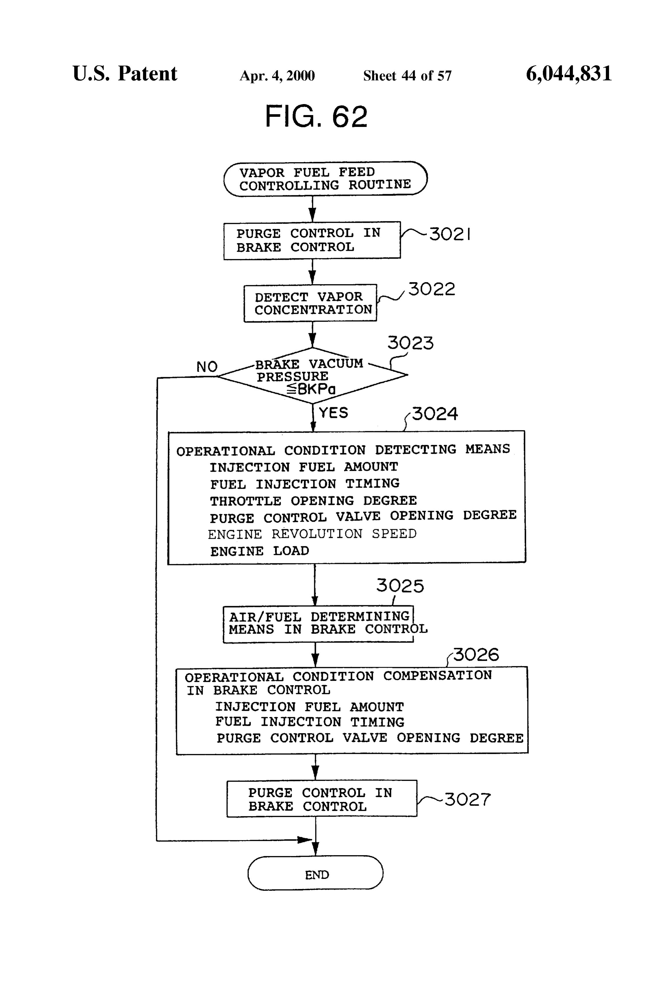
WAPOR FUEL FEED
CONTROLLING ROUTINE
PURGE CONTROL IN 3O2
BRAKE CONTROL
CONCENTRATION
NO BRAKE WACUUM
PRESSURE
SBKPO
OPERATIONAL CONDITION DETECTING MEANS
INJECTION FUEL AMOUNT
FUEL INJECTION TIMING
THROTTLE OPENING DEGREE
PURGE CONTROL VALVE OPENING DEGREE
ENGINE REVOLUTION SPEED
ENGINE LOAD
AIR/FUEL, DETERMINING
MEANS IN BRAKE CONTROL
OPERATIONAL CONDITION COMPENSATION
IN BRAKE CONTROL
INJECTION FUEL AMOUNT
FUEL INJECTION TIMING
PURGE CONTROL VALVE OPENING DEGREE
PURGE CONTROL IN
Page 46
Drawing sheet — no readable text.
Page 47
Drawing sheet — no readable text.
Page 48
Drawing sheet — no readable text.
Page 49
f NE INTERMEDIATE
NE LARGE
TA (THROTTLE OPENING
DEGREE
Q . OBTAINED FROM MAP IN
P OPERATIONAECONDITION
Qp : TARGET VALUE IN CASE OF
CONTROLLING FLOW RATE
A P = ATMOSPHERIC PRESSURE -
INTAKE MANIFOLD PRESURE
Page 50
Drawing sheet — no readable text.
Page 51
Drawing sheet — no readable text.
Page 52
Drawing sheet — no readable text.
Page 53
Drawing sheet — no readable text.
Page 54
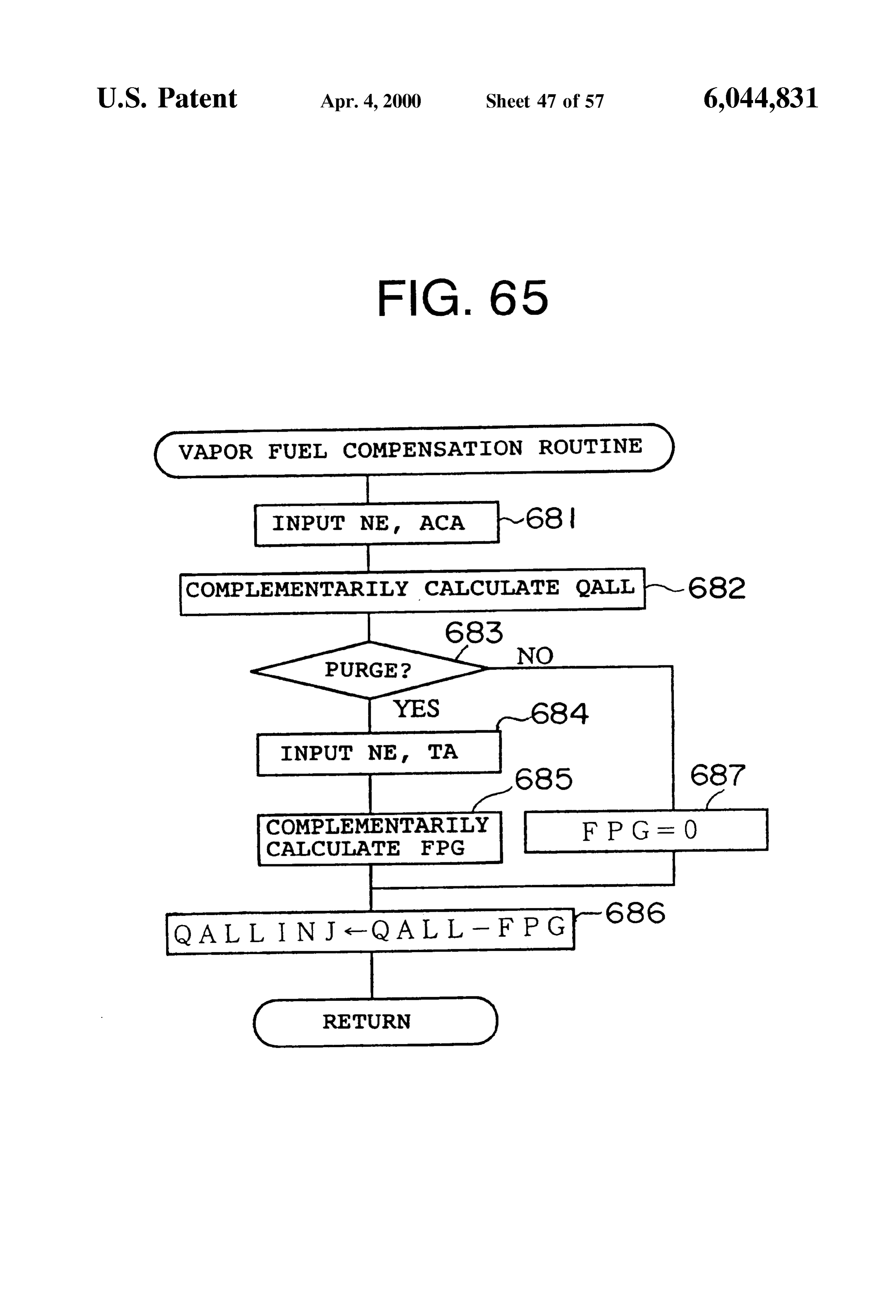
WAPOR FUEL COMPENSATION ROUTINE
COMPLEMENTARILY CALCULATE OALL 4OO2
segreed. No
INPUT DNL, FPG
CALCULATE
PURGE CONTROL VALVE 4O2
CONTROL OUTPUT V (Qp)
CALCULATION AINJ (FPG) BASED ON FPR
AINU-AINUO-AINJ (fpg)
Page 55
Drawing sheet — no readable text.
Page 56
Drawing sheet — no readable text.
Page 57
Drawing sheet — no readable text.
Page 58
Drawing sheet — no readable text.
Page 59
FUEL WAPOR FEED CONTROLLING By the way, a fuel vapor feed controlling apparatus for a APPARATUS FOR LEAN BURN TYPE lean burn type internal combustion engine for temporarily INTERNAL COMBUSTION ENGINE storing the fuel vapor (vapor) from the fuel reservoir or the like in a canister and feeding the Stored vapor into the intake
BACKGROUND OF THE INVENTION System in response to the operational condition of the 1. Field of the Invention internal combustion engine is well known (Japanese Patent Application Laid-Open No. Hei 4-194354).
The present invention relates to a fuel vapor feed con In this System, a purge control valve is interposed in a trolling apparatus for a lean burn type internal combustion purge passage for connecting the canister for fuel Vapor engine for feeding fuel vapor (vapor) generated in, for adsorption and the intake passage for fuel evaporation. example, a fuel reservoir to an intake System in response to Then, the purge control valve is controlled So that a Suitable an operational condition of the lean burn type internal amount of fuel purge (which is an amount of the vapor combustion engine. introduced into the intake passage, and which will herein 2. Description of the Related Art after be referred to as a purge amount) may be obtained in Conventionally, a generally used engine, the fuel from a 15 response to the operational condition of the engine (for fuel injection valve is injected to an intake port So that example, in the case where the engine load is large, the vapor uniform or homogeneous mixture of the fuel and air is fed is fed).
to a combustion chamber in advance. An intake passage is However, in the lean combustion region, Since the device opened/closed by a throttle Valve which works in coopera for detecting the air/fuel ratio is not provided, in many cases, tion with an accelerator operation. there is no indeX or factor for controlling the fuel purge An amount of intake air (finally, an amount of gas amount.
uniformly mixed fuel and air) to be fed in the combustion More Specifically, in the conventional internal combustion chamber of the engine is adjusted by the open/close opera engine, an air/fuel ratio Sensor Such as an oxygen Sensor or tion of the throttle valve to thereby control the engine output. the like is usually interposed in the exhaust passage, and the However, in the technology depending upon the above 25 actual air/fuel ratio is detected on the basis of the output described So-called homogeneous combustion, a large intake Signal therefrom. A fuel injection amount or the like is Vacuum is generated in the throttling action of the throttle suitably controlled in a feed-back manner so that the air/fuel Valve So that a pumping loSS is remarkable to reduce the ratio of the mixture Separately calculated may be the target efficiency. In contrast, a So-called “Stratified combustion' air/fuel ratio. However, in the above-described oxygen technology is well known in which the throttle degree of the Sensor, the detection is performed around the target air/fuel throttle valve is made small and the fuel is fed directly to the ratio (A/F) of, for example, 14.5. In the case where the combustion chamber whereby a combustible mixture is air/fuel ratio exceeds this, it is impossible to detect the purge present in the Vicinity of a Spark plug to increase an air/fuel amount.
ratio of the portion in question to enhance ignitability. In this For this reason, when the fuel vapor feed amount is technology, when the engine is operated in a low load, the 35 controlled in Such a lean combustion region, in the case injected fuel is locally fed to an around the Spark plug, and where the air/fuel ratio is not detected or in the case where at the same time, the throttle valve is fully opened to execute the precision of the detected air/fuel ratio is worse, the the Stratified combustion. As a result, the pumping loSS is precision of the calculation of the purge amount becomes reduced and the fuel consumption rate is enhanced. worse. Then, if the fuel vapor feed controlling apparatus is 40 controlled in accordance with the purge amount determined
The internal combustion engine for the above-described
"Stratified combustion” takes combustion conditions Such as by a vacuum pressure, there is a fear that a misfire or a Surge a Stratified combustion, a weak Stratified combustion, a would be generated when the vapor is rich. homogeneous lean combustion and a homogeneous com Also, the case where the load of the engine is shifted from bustion in this order when the load is changed from a low 45 a high level to a low level means the same as the case the level to a high level, for example. combustion condition is shifted from the homogeneous AS described above, the Stratified combustion means a combustion or homogeneous lean combustion to the Strati combustion in which a mixture gas layer having a high fied combustion or the weak stratified combustion or the air/fuel ratio is present in the vicinity of a Spark plug to form like. In Such a case, the purge-prohibition is Set. The a layer with respect to the other gas in the other portion. 50 combustion condition is unstable by the purge gas fed to the The weak Stratified combustion means the case where the combustion chamber with a time lag due to the purge Stratified degree is Small in comparison with the Stratified transfer delay through the intake pipe when the combustion combustion. conditions are changed. As a result, there is a fear that a rich The homogeneous lean combustion means the case where misfire and a Surge would be generated.
the fuel and air are homogeneous but the ratio of the fuel is 55 SUMMARY OF THE INVENTION low. In View of the above, the present invention has been made, The homogeneous combustion means the case where the and therefore an object of the present invention is to provide fuel and air are homogeneous and the ratio of the fuel is a fuel vapor feed controlling apparatus for a lean burn high. internal combustion engine, in which when a fuel vapor is Also, in the case where Such a “stratified combustion” 60 fed into the lean burn internal combustion engine, even in takes place or the lean burn takes place, in Some cases, Swirls the case where the air/fuel ratio is not detected, or in the case would be formed in the mixture of the injected fuel. Namely, where the detecting air/fuel ratio precision is not a swirl control valve (SCV) is provided in the intake port and Satisfactory, it is possible to Suppress a rich misfire or a Surge the opening degree of the SCV is adjusted to thereby control without degrading the calculation of the feed amount of the the Strength of the Swirls. As a result, it is possible to 65 fuel vapor.
enhance the combustion property with a Small amount offed Another object of the present invention is to provide a fuel fuel. Vapor feed controlling apparatus for a lean burn internal
Page 60
combustion engine, in the idle operation, the base fuel is injected from the fuel injection valve is compensated by the effectively saved and it is possible to keep a stability of the fuel purge amount.
idle Revolution Speed irrespective of the concentration of However, if this technology is applied to the engine that the vapor. may take the lean combustion, the following problems Still another object of the present invention is to provide occur. Namely, in the lean combustion region, it would be a fuel vapor feed controlling apparatus for a lean burn difficult to exactly detect the actual air/fuel ratio with the internal combustion engine, in which even in the case where current oxygen Sensor. There is a case where no indeX for the misfire or Surge due to the purge occurs, it is possible to exactly controlling the fuel purge amount is provided. effectively reduce the fuel and to keep a good drivability to More Specifically, an air/fuel ratio Sensor Such as an enhance the fuel consumption rate. oxygen Sensor is disposed in the exhaust passage of the Yet another object of the present invention is to provide a conventional engine, the actual air/fuel ratio is detected by fuel vapor feed controlling apparatus for a lean burn internal its output signal, and the fuel injection amount or the like is combustion engine, in which in Switching combustion fed back Suitably so that the air/fuel ratio of the mixture modes, it is possible to prevent the degradation of the 15 becomes the target air/fuel ratio calculated in another way. combustion. However, the above-described sensor detects the air/fuel By the way, in an internal combustion engine, in order to ratio in the case where the air/fuel ratio (A/F) is at, for purify the exhaust gas, in many cases, an NOx absorbing example, the Stoichiometric one. If the air/fuel ratio exceeds reducer catalyst is disposed in an exhaust passage. In the this, it is impossible to exactly detect the air/fuel ratio or to case where an NOX absorbing reducer catalyst is disposed in detect the purge amount.
an exhaust passage in order to purify the NOX contained in For this reason, in Such a lean combustion region, when the exhaust gas, in the lean combustion (Stratified the fuel vapor feed amount is to be controlled, in the case combustion) condition, it is likely that the NOx to be trapped where the air/fuel ratio is not detected or in the case where by the catalyst is Saturated and the vacuum pressure within the detected air/fuel ratio is not correct, the calculation a brake booster for assisting the brake operation with the 25 precision of the purge amount becomes worse. Then, if the Vacuum pressure would be insufficient. control based upon Such a poor precision detection is For this reason, it is necessary to forcibly discharge and executed, the exhaust emission is worse or the Spark Smoke purify the NOx absorbed, and in order to keep the brake or misfire would occur.
Vacuum preSSure, it is necessary to temporarily close the In addition, in the case where the purge amount is detected throttle valve to lower the air/fuel ratio to enrich the mixture more than the actual one, the fuel injection amount is in the Stoichiometric air/fuel ratio or in the rich condition. reduced by compensation. -In Such a case, if the injection Then, if the air/fuel ratio is controlled in the rich condition, timing is fixed, the fuel amount around the Spark plug is and the further fuel vapor is fed, there is a fear that the insufficient to cause a misfire.
air/fuel ratio to be controlled is deviated from the necessary Still further another object of the present invention is to air/fuel ratio. As a result, the combustion State is unstable to 35 provide a fuel vapor feed controlling apparatus for a lean cause a rich misfire. burn internal combustion engine, for feeding the fuel Vapor Also, in the lean combustion (stratified combustion) State, to the lean burn engine, in which it is possible to Suppress at a high land, an air density (intake density) is Small. an unstable combustion with an output variation, and the Accordingly, the air/fuel ratio tends to be rich in comparison Suitable fuel injection is maintained to keep the Suitable with the low land. Accordingly, if the purge is executed in 40 combustion.
Such a condition, the lean combustion or Stratified combus (1) According to the present invention, a first feature of tion is unstable. The misfire would occur. the invention resides in a fuel vapor feed controlling appa Further another object of the present invention is to ratus for a lean burn internal combustion engine comprising: provide a fuel vapor feed controlling apparatus for a lean a purge passage for purging fuel Vapor, generated from a fuel burn internal combustion engine, in which the purge is 45 Storing means for Storing fuel of the internal combustion effected to the intake System in the internal engine in order engine, to an intake System of the internal combustion to process the fuel vapor generated from the fuel Storing engine; a purge controlling means for controlling a fuel means, and in which the air/fuel ratio is Suitable controlled Vapor amount, to be introduced from the purge passage to in the lean combustion (Stratified combustion) state to the intake System, in response to an operational condition of thereby avoid the generation of the rich misfire caused by the 50 the internal combustion engine; and a first compensation turbulence of the air/fuel ratio. means for compensating for the fuel vapor amount So that an Next, an example of a fuel vapor feed controlling appa engine revolution Speed of the internal combustion engine ratus for feeding a Stored vapor into the intake System in may be identical with a target Revolution Speed, character response to the operational condition of the internal com ized in that the purge controlling means performs a purge bustion engine while Storing temporarily the fuel Vapor from 55 control on the basis of a compensation value compensated the fuel reservoir or the like in the canister is shown in for by the first compensation means. Japanese Patent Application Laid-Open No. 8-177572. The purge control means for controlling a fuel vapor In this technique, a purge control valve is provided in a amount, to be introduced from the purge passage to the purge passage, for fuel vapor, for connecting the canister for intake System, in response to an operational condition of the absorbing the fuel vapor and the intake passage. The purge 60 internal combustion engine may include, for example, a control valve is duty controlled in order to obtain the Suitable purge control valve disposed in the purge passage for fuel purge amount (introduction amount of the vapor to the controlling the fuel vapor amount of the fuel vapor to be intake passage, hereinafter referred to as a purge amount) in introduced into the intake System, an operational condition response to the operational condition of the engine. Also, in detecting means for detecting the operational condition of this technique, the learned control is performed to SuppreSS 65 the internal combustion engine and a purge control valve the variation of the air/fuel ratio by using an oxygen Sensor. controlling means for controlling an opening degree of the Then, in the lean control, the fuel injection amount actually purge control valve in response to the operational condition
Page 61
S 6 detected by the operational condition detecting means. In the amount is compensated for in response to the engine revo purge control, it is easiest to adjust the opening degree of the lution Speed by the Second compensation means. The purge purge control valve. The invention is not limited to this. This Valve opening degree is compensated for and controlled in may be applied also to the following features. However, for accordance with the compensation value. the Sake of simplification of the explanation, an example of In many cases, in the lean burn internal combustion the opening degree adjustment of the purge control valve is engine, in the normal operational condition, the throttle used for purge control. Valve is operated at a Substantially fully opened State. Since the fuel is injected directly to the interior of the sleeve, it is
The fuel vapor generated from the fuel Storing means is unnecessary fed through the purge passage to the intake System of the the intake air.to control the mixture condition by controlling internal combustion engine. In this case, the purge control For instance, if the throttle valve is fully opened substan Valve provided in the purge passage is controlled So that the tially fuel vapor amount of the fuel vapor to be introduced into the intakeover the entire region of the operation conditions, the intake System is controlled. Namely, the operational condi For this reason, ifi.e., air amount, the vacuum pressure is kept constant.
tion of the internal combustion engine is detected by the response to at leasttheonepurge amount is to be controlled in operational condition detecting means. The purge valve is (=air amount/engine revolutionairspeed), 15 of the intake amount, the load and intake pipe controlled by the purge control valve controlling means in its Vacuum pressure, in the case where the same amount of operational condition. In this case, the first compensation purge is effected for the Stratified combustion at a low means compensates for the fuel vapor amount So that an Revolution speed and for the homogeneous combustion at a engine revolution Speed of the internal combustion engine high Revolution speed, the combustion instability or misfire may be identical with a target Revolution Speed. The purge would occur on the low Revolution speed side. Therefore, in control valve controlling means controls the purge control the lean burn internal combustion engine in which the intake Valve on the basis of the compensation value compensated pipe Vacuum pressure is kept Substantially constant, the by the first compensation means. For this reason, the purge purge amount is controlled in response to the engine revo amount corresponds to the compensation value and the lution Speed.
engine revolution Speed is controlled Suitably to be identical 25 (3) According to the present invention, a third feature of with the target Revolution Speed. the invention resides in a fuel vapor feed controlling appa (1-1) In this case, the present invention may be Suitably ratus for a lean burn internal combustion engine comprising: applied to the case where the target Revolution Speed of the Storing passage a purge means for purging fuel Vapor, generated from a fuel for Storing fuel of the internal combustion internal combustion engine to be referenced by the first engine, to an intake System of the internal combustion compensation means is the idle Revolution Speed. engine; a purge controlling means for controlling a fuel Namely, if the control according to the present invention Vapor amount, to be introduced from the purge passage to is applied to the idle mode of the lean combustion State, it the intake System, in response to an operational condition of is possible to keep a Suitable lean combustion in the idle the internal combustion engine; and a third compensation mode.
35 means for compensating for the fuel vapor amount in (1-2) Furthermore, the fuel feed amount controlling response to an output variation of the internal combustion means for adjusting the fuel feed amount in correspondence engine, characterized in that the purge controlling means with the compensation result by the first compensation performs a purge control on the basis of a compensation means in the idle mode of the lean combustion State may be value compensated for by the third compensation means. provided. 40 In this case, the fuel vapor amount is compensated for in Thus, the Suitable fuel feed amount is ensured in the idle response to the output variation of the internal combustion mode in the lean combustion State. The good idle operation engine, and the purge is controlled in accordance with the is ensured. compensated amount. It is therefore possible to maintain the (2) According to the present invention, a second feature of Smooth operation of the internal combustion engine even if the invention resides in a fuel vapor feed controlling appa 45 the output variation occurs.
ratus for a lean burn internal combustion engine comprising: (3-1) In this case, it is possible to provide a fuel feed a purge passage for purging fuel Vapor, generated from a fuel amount controlling means for adjusting the fuel feed amount Storing means for Storing fuel of the internal combustion in response to the output variation of the internal combustion engine, to an intake System of the internal combustion engine. According to this, Since the fuel is fed in response to engine; a purge controlling means for controlling a fuel 50 the output variation of the internal combustion engine, it is Vapor amount, to be introduced from the purge passage to possible to further ensure the suitable fuel amount. the intake System, in response to an operational condition of (4) According to the present invention, a fourth feature of the internal combustion engine; and a Second compensation the invention resides in a fuel vapor feed controlling appa means for compensating for the fuel vapor amount in ratus for a lean burn internal combustion engine comprising: response to an engine revolution Speed of the internal 55 a purge passage for purging fuel Vapor, generated from a fuel combustion engine, wherein the purge controlling means Storing means for Storing fuel of the internal combustion performs a purge control on the basis of a compensation engine, to an intake System of the internal combustion value compensated for by the Second compensation means. engine; a purge controlling means for controlling a fuel It is preferable that the Second feature is applied to a lean Vapor amount, to be introduced from the purge passage to burn internal combustion engine (for example, a sleeve 60 the intake System, in response to an operational condition of interior injection type internal combustion engine) in which the internal combustion engine; and a fourth compensation a change of the intake pipe vacuum pressure is Small over means for compensating for the fuel vapor amount in the entire region of the operational condition (Substantially response to a combustion condition of the internal combus constant), or the intake air amount per unit revolution is kept tion engine, characterized in that the purge controlling Substantially constant. In the Second feature, Specifically, the 65 means performs a purge control on the basis of a compen opening degree of the purge valve is controlled in response sation value compensated for by the fourth compensation to the operational condition. In this case, the fuel vapor CS.
Page 62
In this case, the fuel vapor amount is compensated for in Storing means for Storing the fuel for driving the internal response to the combustion condition of the mixture. The combustion engine. Accordingly, according to the present combustion condition means the combustion State of the invention, the above-described purge passage may commu mixture in the combustion chamber, for example, the degree nicate the intake System of the internal combustion engine of the Stratified combustion, or the combustion Switching and the canister with each other. condition among the Stratified combustion, the weak Strati (5-4) The present invention may be applied to a wide fied combustion, homogeneous lean combustion and the variety of lean burn internal combustion engines including homogeneous combustion. The fuel vapor amount is com the intake pipe injection type one as well as the sleeve pensated in response to each condition to ensure the opti interior direct fuel injection type lean burn engine except for mum fuel amount in response to each condition. the above-described feature (2). (4-1) With respect to the fourth feature, a control delay (6) A fifth feature of the present invention is directed to means for delaying a time to start a change of an opening the case in which if the mixture would be abruptly enriched degree of a purge valve or a change of a fuel injection expectedmidwayin the
of the lean combustion operation, this is reduce the feed of the fuel vapor. The fifth condition change in Switching combustion conditions may feature of the invention be provided. By the delay, it is possible to prevent from ling apparatus for a leanresides 15 in a fuel vapor feed control burn internal combustion engine hunching in Switching. comprising: a purge passage for purging fuel Vapor, gener (4-2) Furthermore, a change speed controlling means for ated from a fuel Storing means for Storing fuel of the internal controlling an opening degree changing Speed of a purge combustion engine, to an intake System of the internal control valve or a fuel injection condition changing Speed in combustion engine; a purge controlling means for control response to the combustion condition may be provided. ling a fuel vapor amount, to be introduced from the purge Thus, the purge valve opening degree and the fuel injection passage to the intake System, in response to an operational condition are gradually changed in Switching the combus condition of the internal combustion engine; an air/fuel ratio tion states. Therefore, the combustion may be stabilized. judging means for judging a shift from an air/fuel ratio (4-3) In this case, it is possible to change the fuel injection 25 corresponding to a lean combustion to an air/fuel ratio that condition changing Speed at every combustion condition is richer than the former air/fuel ratio in the lean combustion Switch. Thus, the changing Speeds Such as the purge valve operation; and a fuel restricting means for restricting at least opening degree or the like in combustion condition Switch a purge amount out of the purge amount of fuel Vapor are made different from each other, the combustion stability determined by the purge control means and a fuel amount to may be further enhanced in comparison with the case like be injected from a fuel injection valve of the internal (4-3) in which the changing Speed is simply changed. combustion engine when the air/fuel ratio judging means (4-4) Furthermore, it is possible to provide a fuel vapor judges that the air/fuel ratio is to be enriched. feed controlling apparatus provided with a fuel feed amount In the lean burn internal combustion engine according to controlling means for adjusting the feed amount of the fuel the present invention, when the lean combustion operation is in response to the Switch mode upon Switching the combus 35 effected, the fuel Vapor generated in the fuel reservoir is fed tion States of the internal combustion engine. By changing to the intake System. In the lean combustion condition, a the feed amount of the fuel in the combustion mode Switch, Small amount of fuel is fed into a large amount of air. In Such the combustion may be further stabilized. a condition where the fuel amount is Small, the air/fuel ratio of the combustible mixture to be fed into the internal (5) In any one of the first to fourth features of the invention, it is possible to provide an injection condition 40 combustion engine is lean. Then, in the operational condi changing means for changing the fuel injection condition in tion where air/fuel ratio is enriched, the affect of the fuel response to the compensation of the fuel vapor amount. Vapor against the air/fuel ratio is considerably large. If the fuel injection condition of the fuel injection amount, Therefore, according to the present invention, in the case the fuel injection timing, the fuel injection direction or the whereof the it is judged by the judging means that the air/fuel ratio combustible mixture is richer than the air/fuel ratio of like is changed in response to the compensation of the fuel 45
Vapor amount, it is possible to ensure the more Stable the mixture in the normal lean combustion condition, at least combustion. the fuel vapor amount to be fed is restricted by the fuel (5-1) It is possible to provide a concentration detecting restricting
means. For this reason, the affect given to the ratio is reduced by the fuel vapor is reduced to means for detecting a concentration of the fuel Vapor and a 50 thereby suitably control the air/fuel ratio to prevent the rich fifth compensation means for compensating for an opening misfire without any turbulence. degree of a purge valve or a fuel injection condition in response to the concentration of the fuel vapor. In this case, including as the judgementjudging
In this case, the air/fuel means has a wide concept content not only the case where
Since the opening degree of the purge control valve or the the air/fuel ratio is actually directed fuel injection condition is compensated for in response to the 55 the case where the air/fuel ratio wouldonbetheexpected rich side but also to be rich concentration, the control precision is enhanced. in View of the various conditions. Also, in the air/fuel ratio (5-2) Furthermore, the injection condition changing means changes the injection amount compensation amount judging means, the richer air/fuel ratio than the air/fuel ratio corresponding to the lean combustion means the case where as the fuel injection condition. It is preferable to limit the the air/fuel ratio is relatively enriched. This may mean, for change of the injection amount compensation amount by the 60 example, the case where the Stratified combustion (Strong guard value. lean) to the homogeneous lean combustion (weak lean), the The guard value is used for the restriction So that the case where the lean combustion is changed to the Stoichio change of the compensation amount more than necessary metric air/fuel ratio combustion, the case where the lean may be Suppressed. It is possible to prevent the combustion combustion is changed to the rich combustion, and So on. instability or misfire due to the excessive compensation. 65 Also, the restriction by the fuel restricting means includes (5-3) Incidentally, conventionally, a regular vehicle has a the action for prohibiting the fuel injection or the purge and canister for Storing the fuel Vapor generated from the fuel the action for reducing the feed amount.
Page 63
(6-1) By the way, in a lean burn internal combustion In the case where the vacuum pressure amount detected engine, it is general that the nitrogen oxide reducer catalyst by the vacuum pressure amount detecting means is Smaller is provided in the exhaust System in order to remove the than a predetermined amount, this is the same as the case nitrogen oxide from the exhaust gas. where it is necessary to operate the vacuum pressure pro In this case, in the case where at least the lean combustion ducing means as described in the item (6-2). Accordingly, it Such as a Stratified combustion is effected, the air/fuel ratio is judged that the air/fuel ratio of the combustible mixture is of the combustible mixture is temporarily enriched by the enriched more than the air/fuel ratio of the normal lean rich Spike control means, So that the nitrogen oxide absorbed combustion (Stratified combustion) condition. In this case, it in the nitrogen oxide reducer catalyst provided in the is possible to reduce the purge amount and to prevent the exhaust passage of the internal combustion engine is misfire before the enrichment of the air/fuel ratio in the same released or purified. manner as in the item (6-2).
In Such a case, the air/fuel ratio judging means may be constructed to judge that the air/fuel ratio is in the rich ing an intake an (6-4) Also, intake density detecting means for detect condition when the amount of the nitrogen oxide absorbed judging meansdensity is provided So that the air/fuel ratio may make a judgement on the basis of the to the nitrogen oxide reducer catalyst is larger than a 15 predetermined amount. intake density detected by the intake density detecting
In the case where the amount of the nitrogen oxide absorbed to the nitrogen oxide reducer catalyst is larger than In the case where the intake density is lower than the a predetermined amount, the air/fuel ratio of the combustible reference value, it is judged that the air/fuel ratio of the mixture is temporarily enriched by the rich Spike controlling combustible mixture is enriched more than the air/fuel ratio means So that the nitrogen oxide absorbed in the nitrogen of the normal lean combustion (stratified combustion) con oxide reducer catalyst provided in the exhaust passage of the dition.
internal combustion engine is released or purified. In the case where the vehicle travels in highland, Since the Reversely, this may means that, in the case where the purge amount is reduced when the intake density is lowered, amount of the nitrogen oxide absorbed to the nitrogen oxide it is possible to prevent the misfire caused by the enrichment reducer catalyst is larger than the predetermined amount, the 25 of the air/fuel ratio under the condition that the oxygen per air/fuel ratio of the combustible mixture is richer than the unit volume is insufficient.
air/fuel ratio in the normal lean combustion (Stratified (6-5) When it is judged by the air/fuel judgement means combustion). The structure of air/fuel ratio judging means that the air/fuel ratio is enriched, it is possible to provide an may be simplified because the information to be used in the injection condition changing means for changing the fuel rich Spike controlling means may be used as its judgement injection condition together with the restriction of the purge condition.
amount by the fuel restricting means.
Then, Since the purge amount is reduced before the rich In this case, Since the injection amount is compensated for Spike, the rich misfire may be prevented in advance. as the purge amount is reduced, it is possible to ensure more (6–2) Subsequently, in Some cases, in a vehicle, there is 35 Suitable combustion.
provided a brake booster is provided for assisting a brake operation of the vehicle by utilizing a vacuum pressure (6-6) It is possible to provide a concentration detecting means within the intake passage. In this case, a vacuum producing pensation for detecting a fuel vapor concentration and a com means for producing the vacuum pressure for the brake by means for compensating for the fuel injection throttling the air flow rate of the intake passage is provided. 40 condition or the purge amount in response to the concen In this case, the above-described air/fuel ratio judging tration of the fuel vapor.
means may be constructed to make a judgement in accor Since the purge amount or the fuel injection condition is dance with the operational condition of the vacuum produc compensated for in response to the fuel vapor concentration, ing means. it is possible to ensure more Suitable combustion. The brake booster is operated on the basis of the vacuum 45 (6-7) Incidentally, conventionally, a regular vehicle has a preSSure within the intake passage. In order to maintain the canister for Storing the fuel Vapor generated from the fuel Vacuum preSSure for the brake booster, when the vacuum Storing means for Storing the fuel for driving the internal producing means is operated, the throttle valve is tempo combustion engine. Accordingly, according to the present rarily closed. the intake air amount is reduced to enrich the invention, the above-described purge passage may commu air/fuel ratio. Accordingly, if the case where the vacuum 50 nicate the intake System of the internal combustion engine producing means is to be operated is detected, it is possible and the canister with each other.
to judge that the air/fuel ratio of the combustible mixture is (6-8) The above-described features may be combined as richer than the air/fuel ratio of the normal lean combustion much as possible.
(stratified combustion). (7) According to the present invention, a sixth feature of In this case, the air/fuel ratio is judged directly from the 55 the invention resides in a fuel vapor feed controlling appa Vacuum pressure amount or from the operation for throttling ratus for a lean burn internal combustion engine comprising: the intake amount for increasing the intake pipe vacuum a purge passage for purging fuel Vapor, generated from a fuel preSSure for maintaining the brake vacuum. Accordingly, it Storing means for Storing fuel of the internal combustion is possible to reduce the purge amount before the air/fuel engine, to an intake System of the internal combustion ratio is enriched, to prevent the misfire in advance. 60 engine; a purge controlling means for controlling a fuel (6-3) Furthermore, in the case where the brake booster is Vapor amount, to be introduced from the purge passage to provided, a vacuum preSSure amount detecting means for the intake System, in response to an operational condition of detecting the vacuum preSSure amount within the brake the internal combustion engine; a fuel vapor compensation booster may be provided. In this case, the above-described means for compensating for the fuel vapor amount in air/fuel ratio judging means may be constructed to make a 65 response to an operation condition of the internal combus judgement in accordance with the vacuum amount detected tion engine; an injection amount changing means for chang by the vacuum pressure amount detecting means. ing the fuel injection amount to the internal combustion
Page 64
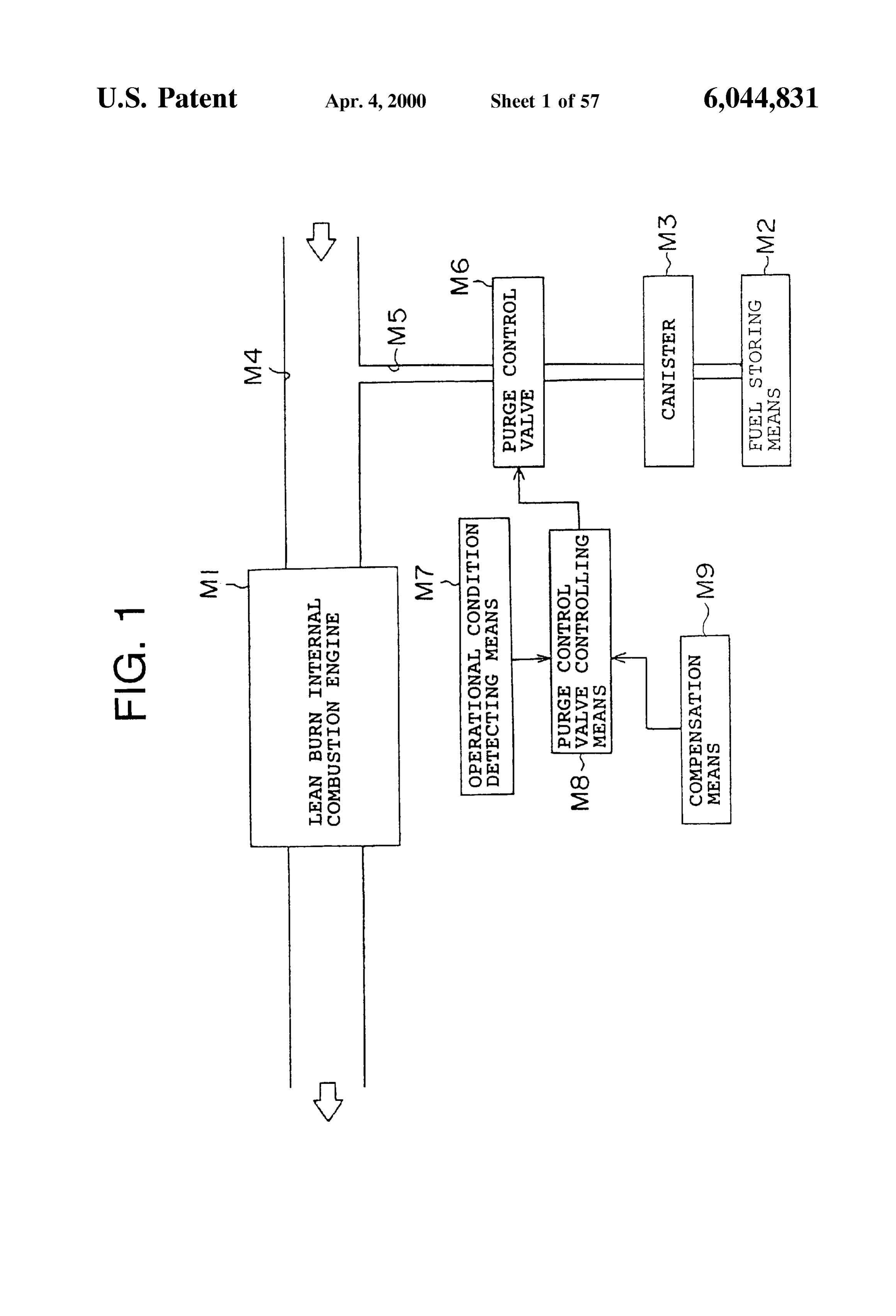
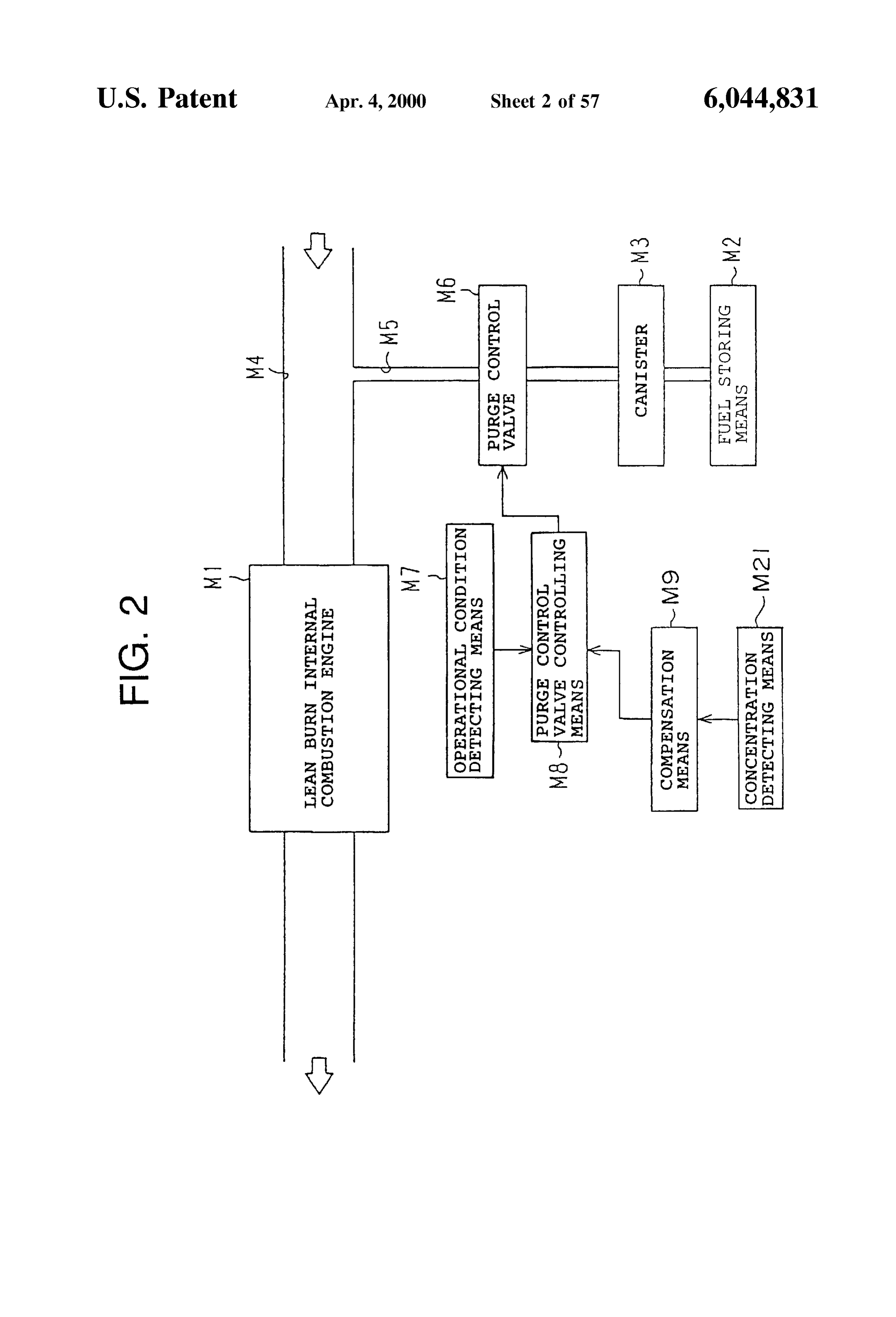
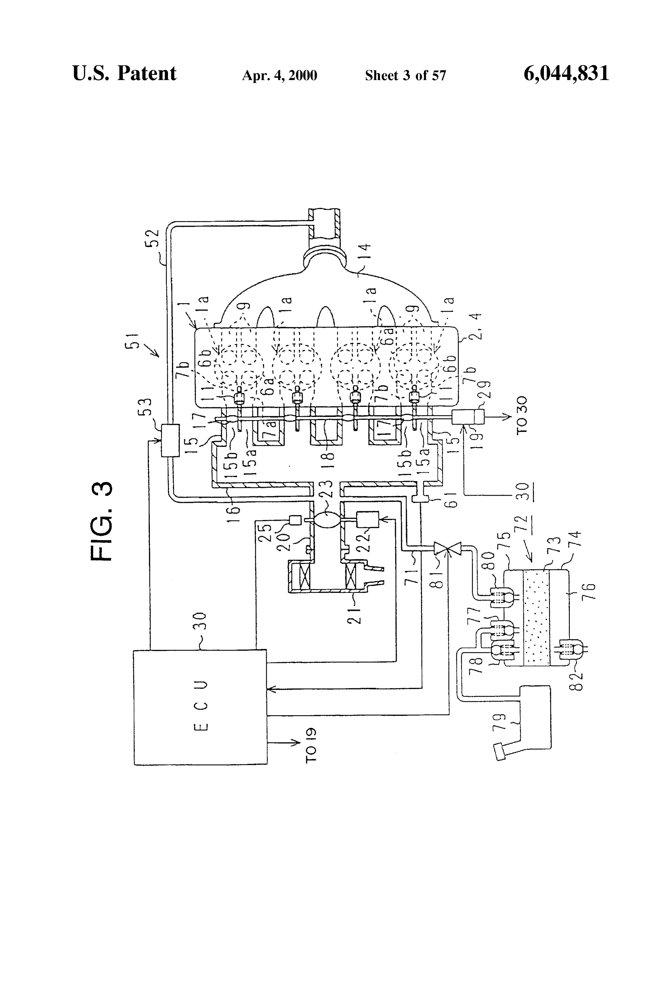
engine on the basis of the compensated fuel Vapor amount; BRIEF DESCRIPTION OF THE DRAWINGS and a correction controlling means for increasing and In the accompanying drawings: decreasing the fuel Vapor amount in response to the opera FIG. 1 is a Schematic diagram showing a basic concept of tional condition after the injection amount change and for the present invention;
controlling a fuel injection timing on an advance Side or on FIG. 2 is a basic conceptional view in case of provision a retard Side. of a concentration detecting means according to the present In this case, an output variation may be exemplified as the invention;
operational condition after the fuel injection amount has FIG. 3 is a schematic view showing a fuel vapor feed been changed. Within the scope of the spirit of the invention, controlling apparatus for an engine in accordance with an it is possible to use other elements showing other operational 1O embodiment of the invention;
conditions Such as an engine revolution Speed, a combustion FIG. 4 is an enlarged cross-sectional view showing a preSSure or the like. cylinder portion of the engine; In the case where the operational condition is not stable FIG. 5 is a mechatronic block diagram showing a Scheme after the fuel injection amount has been changed by the 15 of an ECU;
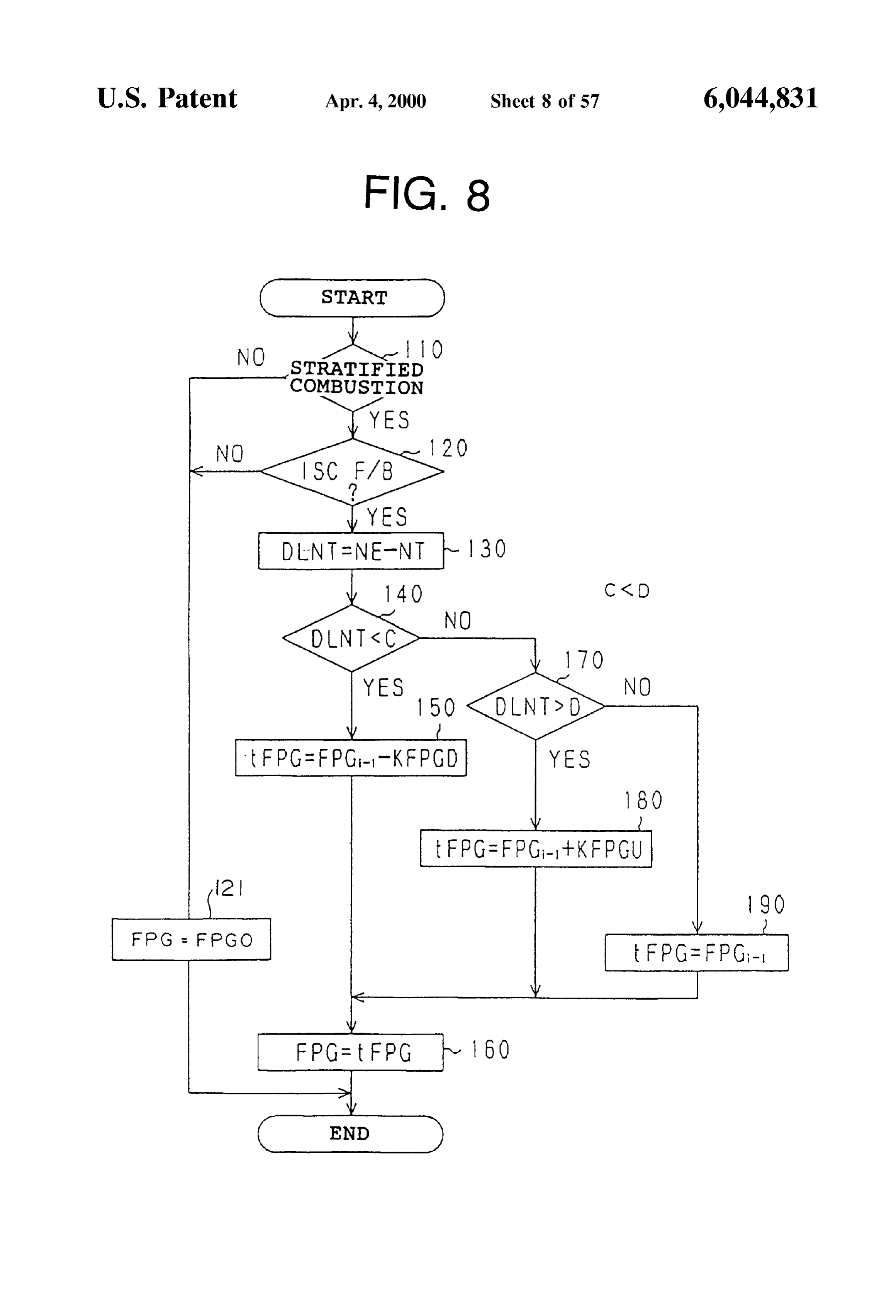
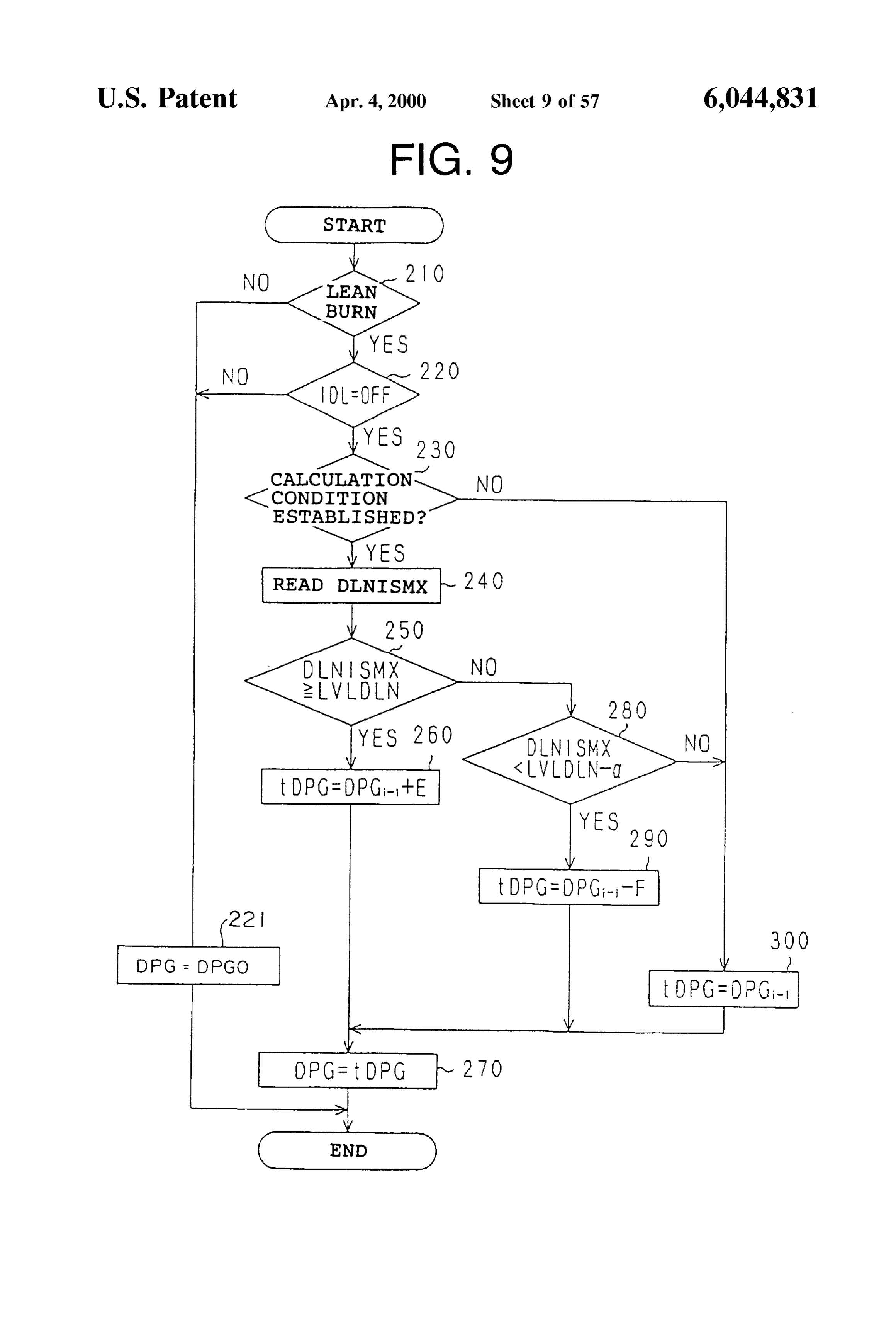
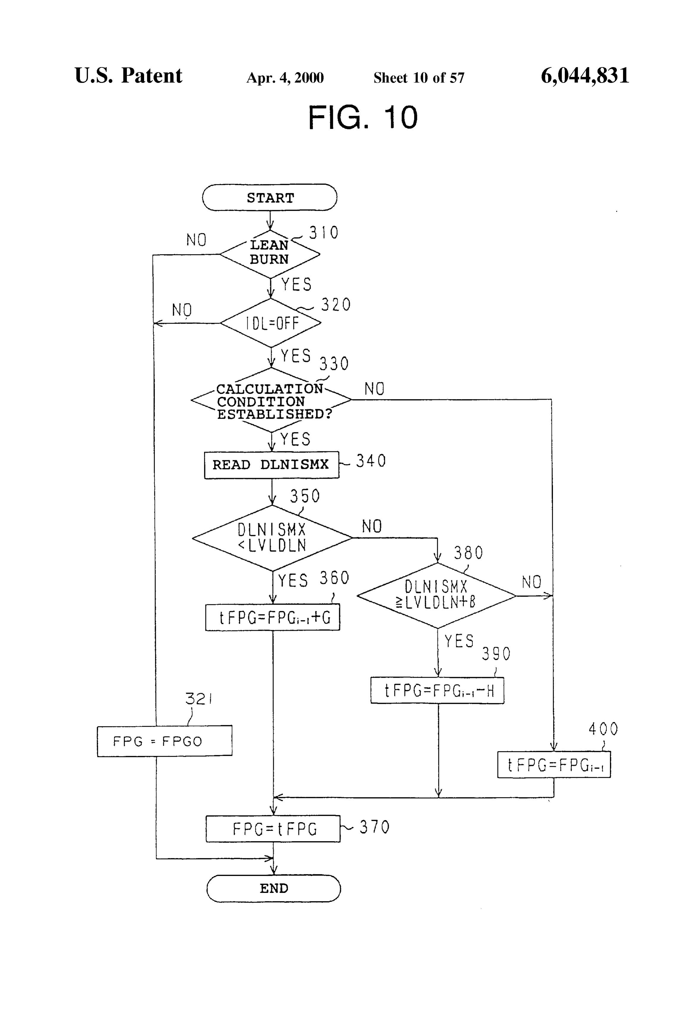
injection amount changing means, for example, in the case FIG. 6 is a flowchart showing a “purge control routine” in where the output variation is not Suppressed, the correction a standstill in an idle state executed by the ECU; controlling means decreases the fuel vapor amount to FIG. 7 is a graph showing a State of a duty control; change the injection timing on the advance Side. FIG. 8 is a flowchart showing a “fuel injection amount In the case where the operational condition is stable after compensation value calculating routine' in a Standstill in an the fuel injection amount has been changed by the injection idle state executed by the ECU;
amount changing means, for example, in the case where the FIG. 9 is a flowchart showing a “purge control routine” in output variation is Suppressed, the correction controlling an idle-off state executed by the ECU; means increases the fuel Vapor amount to change the injec FIG. 10 is a flowchart showing a “fuel injection amount tion timing on the retard Side. 25 compensation value calculating routine' in an idle-off State In the case where the operational condition is not stable executed by the ECU;
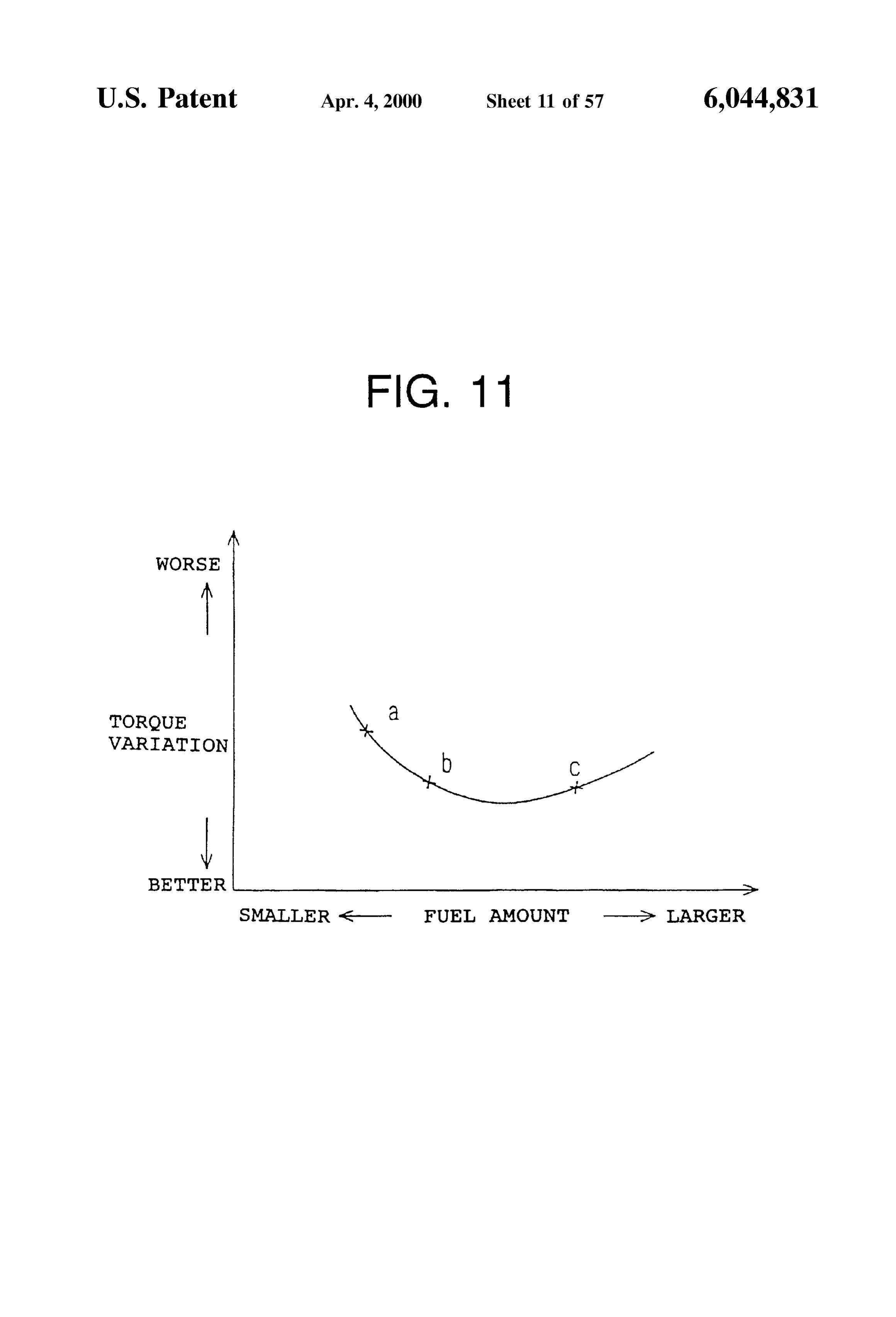
after the fuel injection amount has been changed by the FIG. 11 is a graph showing the characteristics between the injection amount changing means, like the large output torque variation and the fuel amount;
variation, the fuel vapor amount is decreased and at the same FIG. 12 is a flowchart (1) showing a “DPG and FPG time, the injection timing is changed on the advance Side. compensation calculating routine' in a combustion mode Accordingly, the output variation is Suppressed, and the Switch;
operational condition may be directed to the Stability. FIG. 13 is a flowchart (2) showing a “DPG and FPG Also, in the case where the operational condition is stable compensation calculating routine' in the combustion mode after the fuel injection amount has been changed by the Switch;
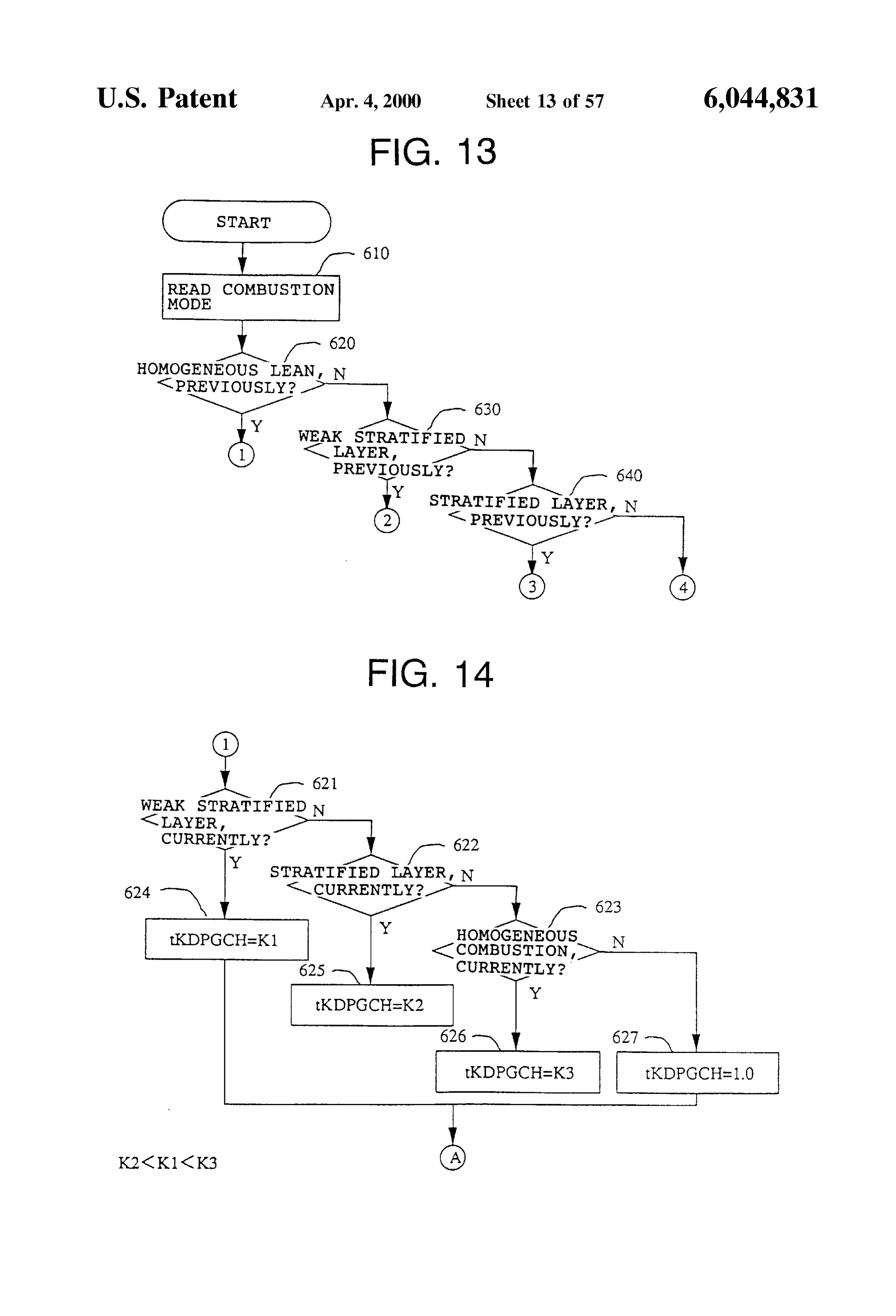
injection amount changing means, it is possible to increase 35 FIG. 14 is a flowchart (3) showing a “DPG and FPG the fuel Vapor amount Since the combustion is Stabilized. It compensation calculating routine' in the combustion mode is therefor possible to readily perform the process of the Switch;
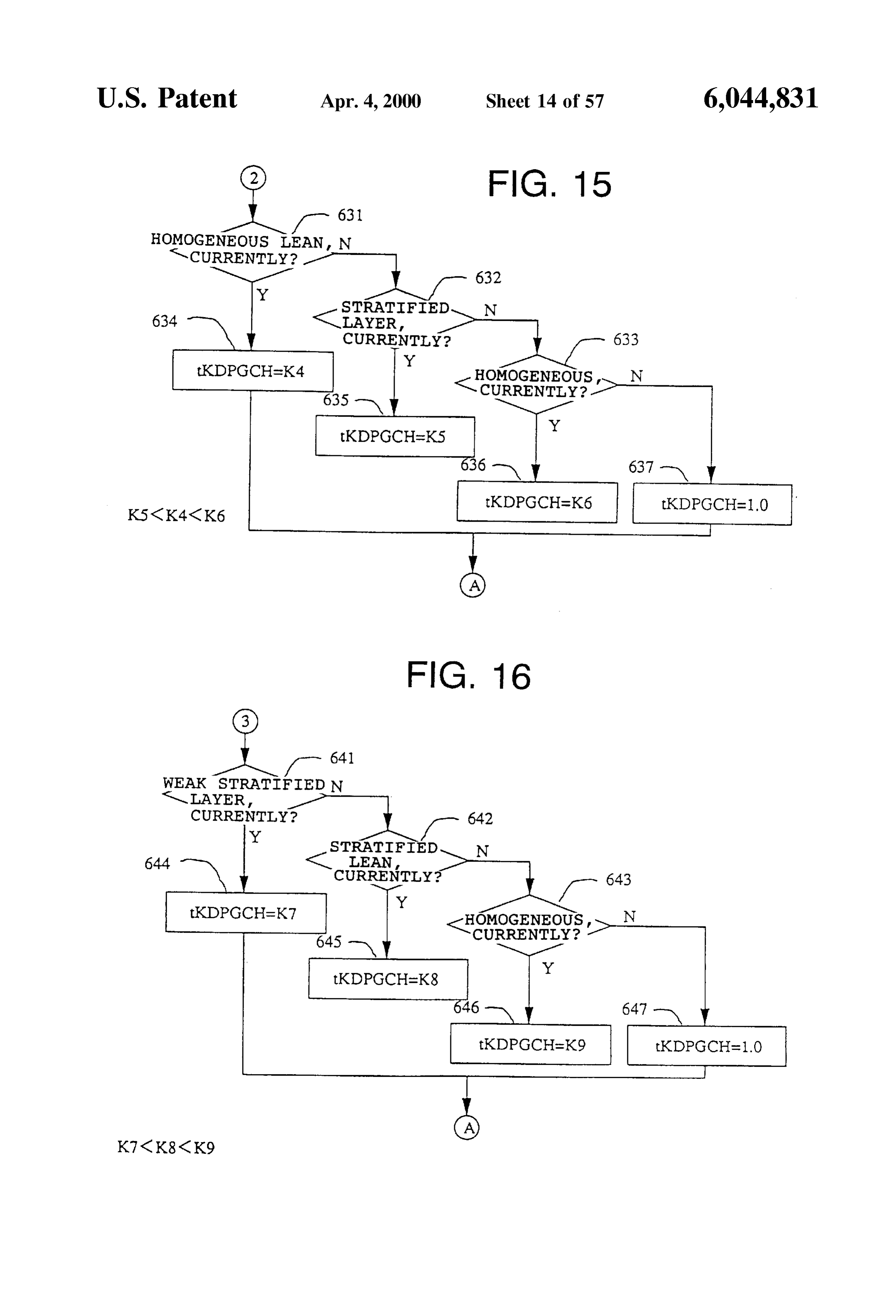
Vapor, and at the same time, it is possible to keep the Stable FIG. 15 is a flowchart (4) showing a “DPG and FPG combustion Since the injection timing is changed on the compensation calculating routine' in the combustion mode retard direction. 40 Switch;
(7-2) Also, it is possible to provide a reference value FIG. 16 is a flowchart (5) showing a “DPG and FPG Setting means for Setting a Stability judgment Standard of the compensation calculating routine' in the combustion mode operational condition in response to the engine revolution Switch;
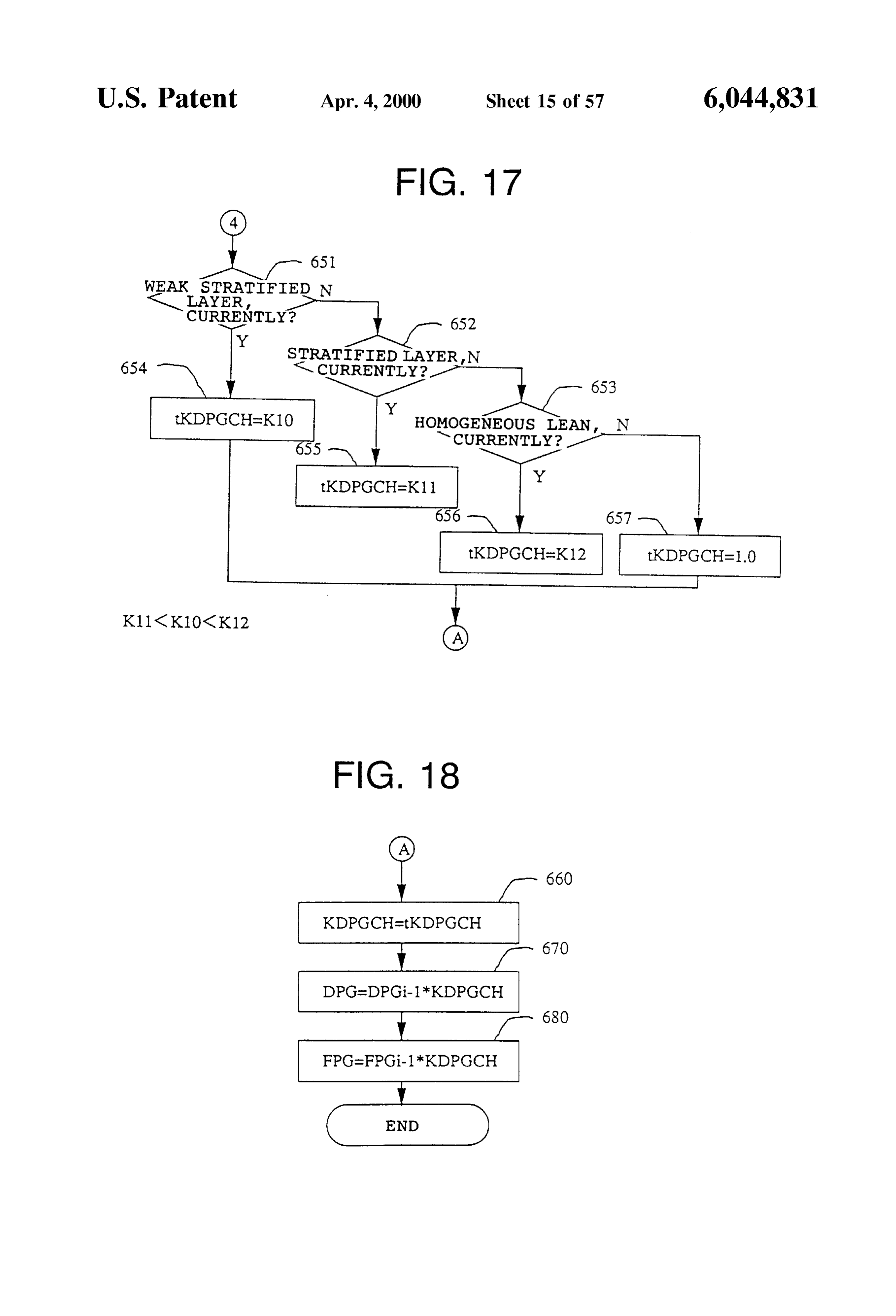
Speed and a Stability judgement means for judging the 45 FIG. 17 is a flowchart (6) showing a “DPG and FPG Stability of the internal combustion engine in accordance compensation calculating routine' in the combustion mode with a change width on the basis of the reference value Set Switch;
by the reference value Setting means. FIG. 18 is a flowchart (7) showing a “DPG and FPG Thus, it is possible to judge the Stability with a variation compensation calculating routine' in the combustion mode width from the reference value, and it is possible to control 50 Switch;
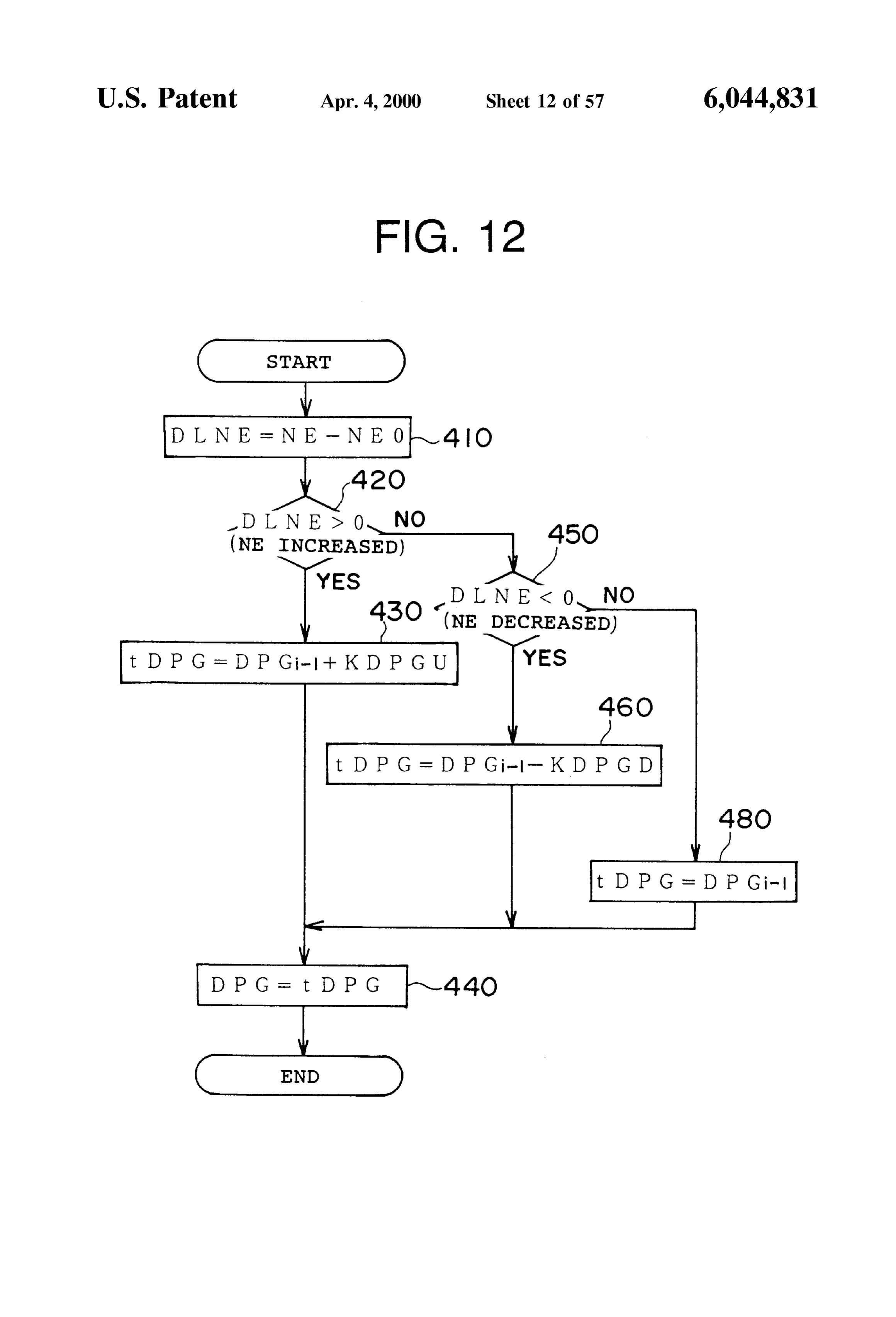
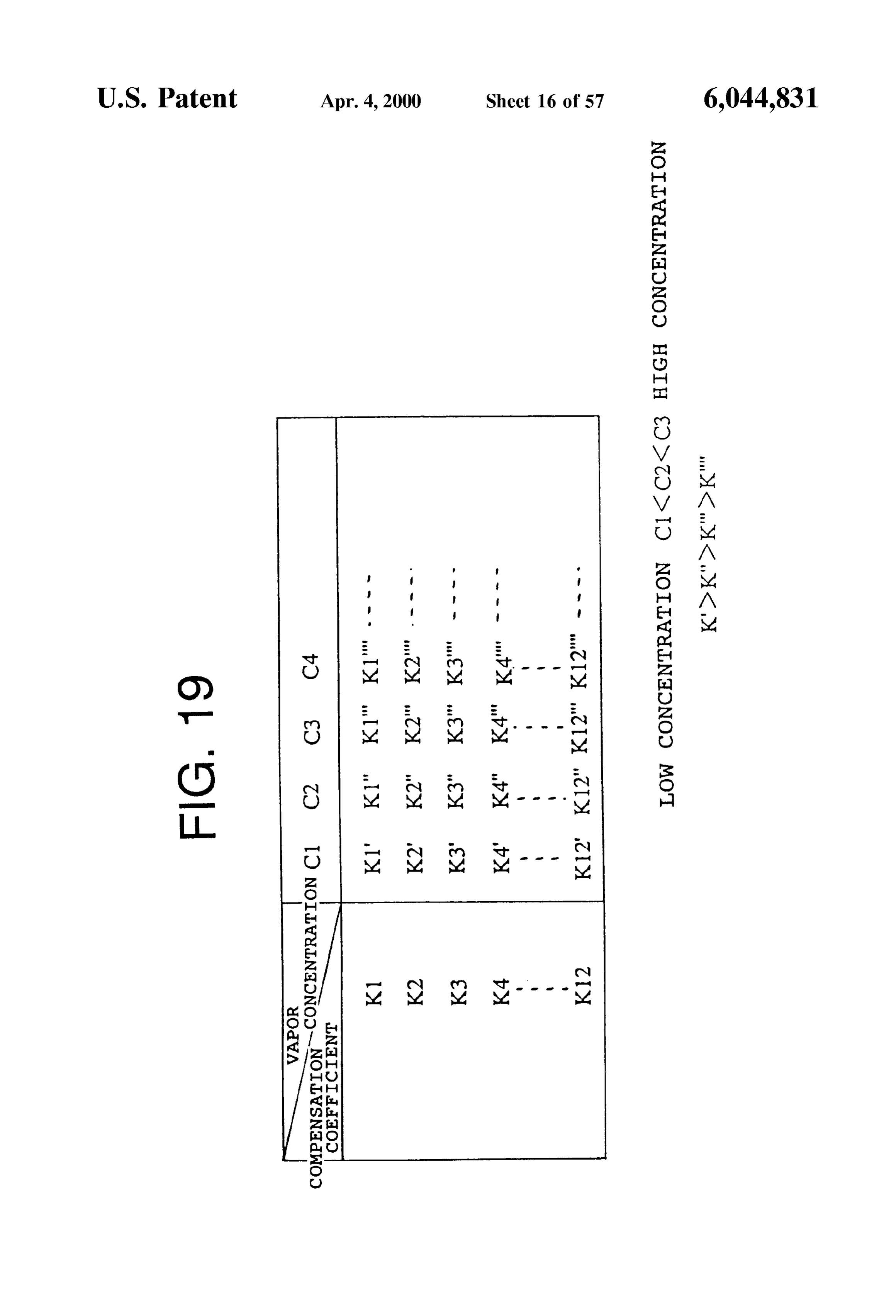
the fuel vapor amount in response to the variation width, to FIG. 19 is a chart showing a relationship between the make it easy the control. Also, at a high Revolution Speed or Vapor concentration and the compensation coefficient used in the homogeneous combustion, the variation width is in the control shown in FIGS. 12 to 18;
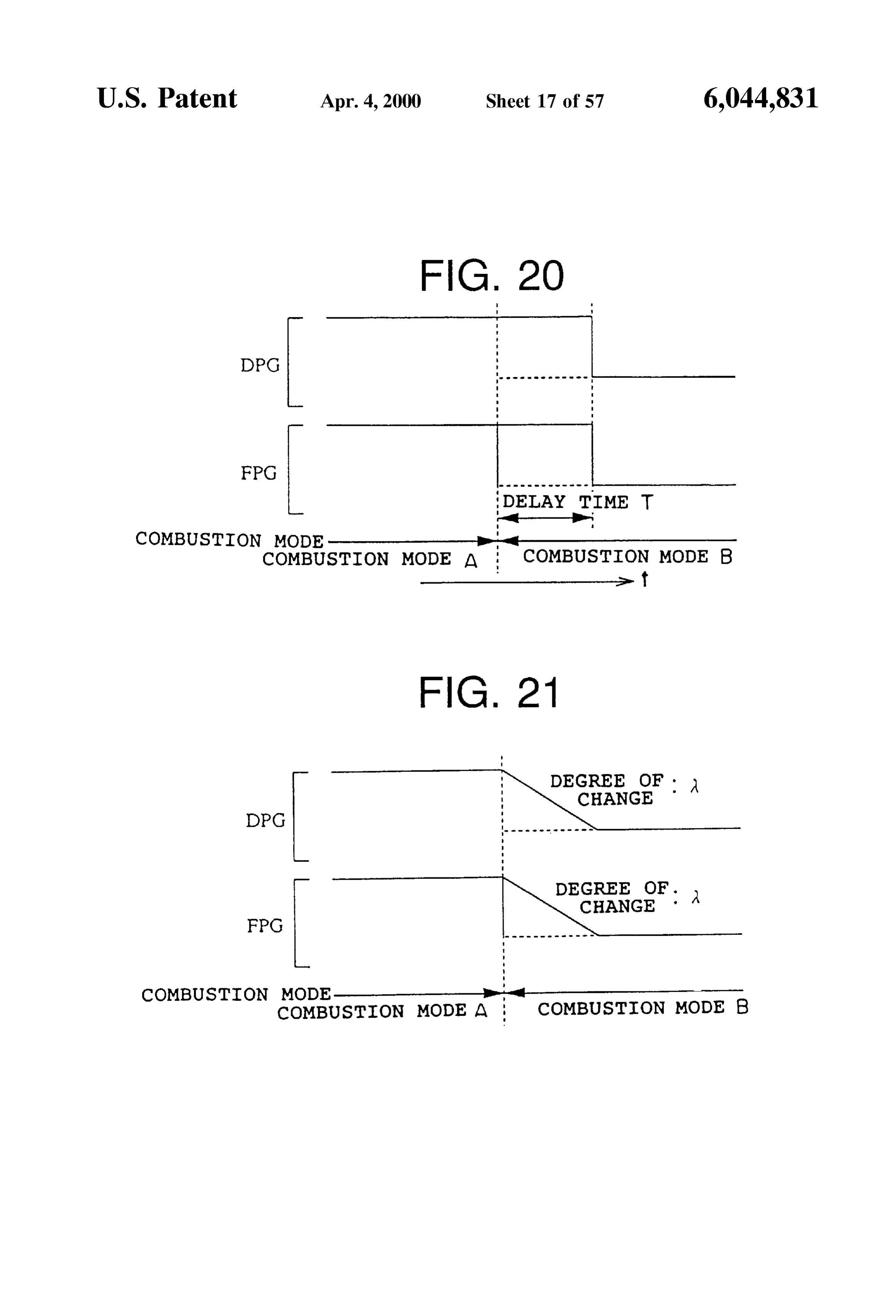
narrow. The compensation is Smaller than the compensation FIG. 20 is a timing chart showing a delay control by a amount at a low Revolution Speed or in the Stratified 55 control delay means upon Switching the mode, combustion (lean burn). As a result, it is possible to prevent FIG. 21 is a timing chart showing a condition in which the the malfunction of the compensation of the fuel injection change caused by the delay control shown in FIG. 20 is amount. made gentle;
(7-3) Furthermore, the operational condition includes a FIG. 22 is a concept view showing the change of the change rate ADLN of the torque variation of the internal 60 degree of change of the delay control caused by the Switch combustion engine and a torque variation change ATDLN of pattern;
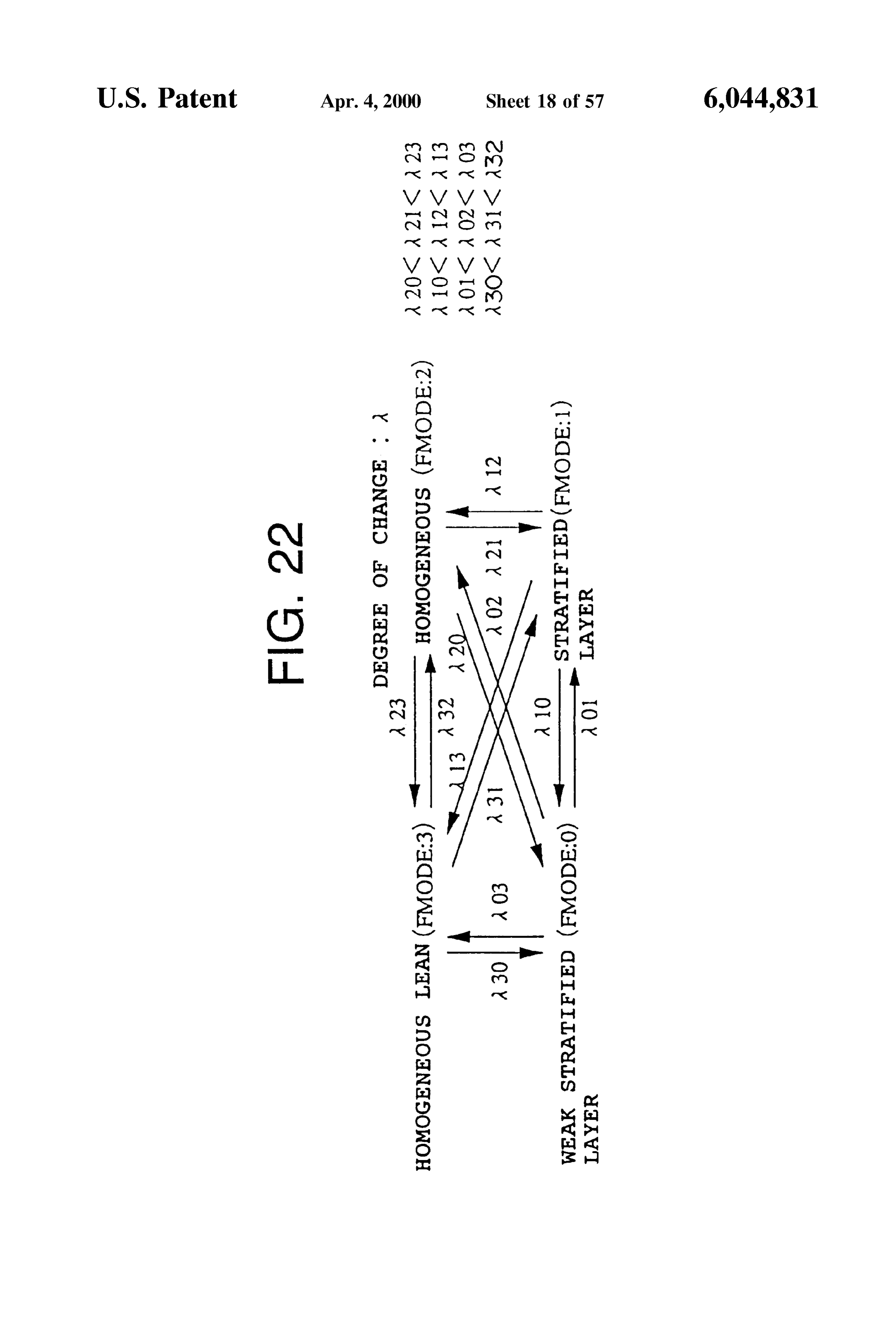
the internal combustion engine. It is possible to provide a FIG. 23 is a flowchart showing a compensation control compensation means for compensating for at least one of the example of a fuel vapor amount;
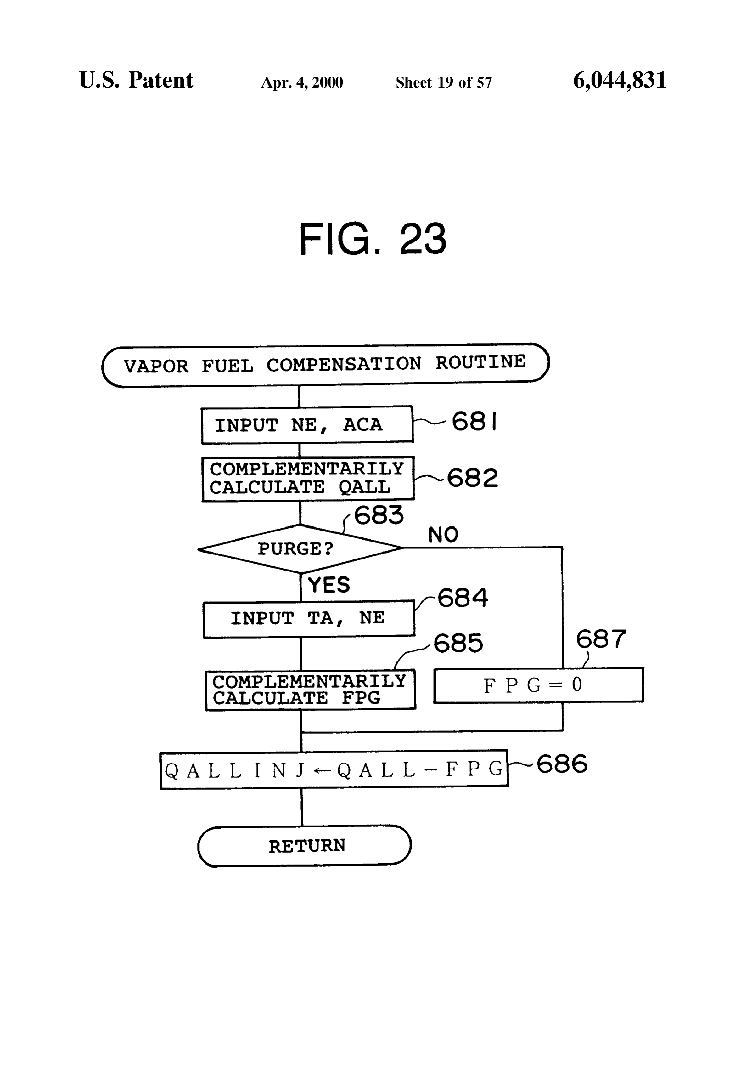
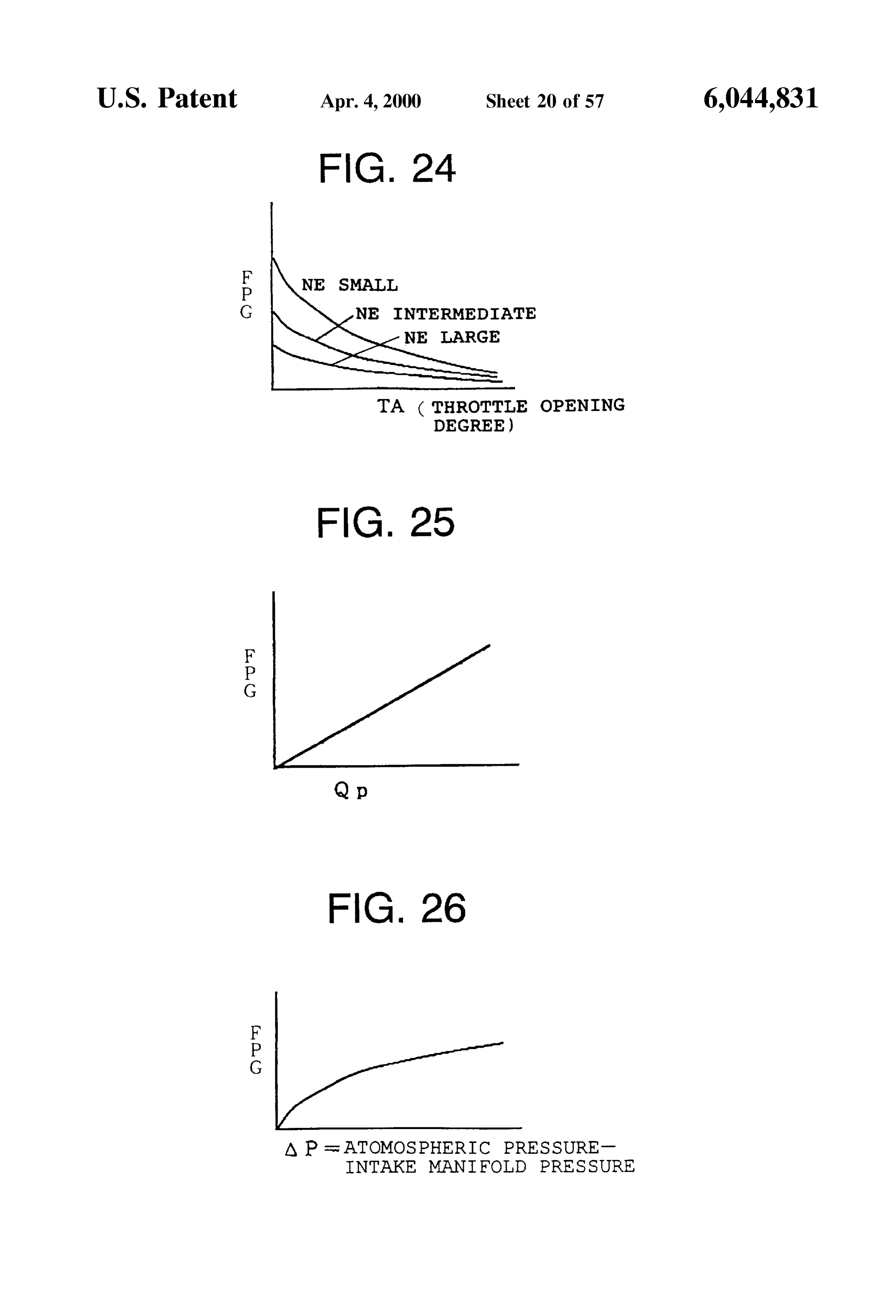
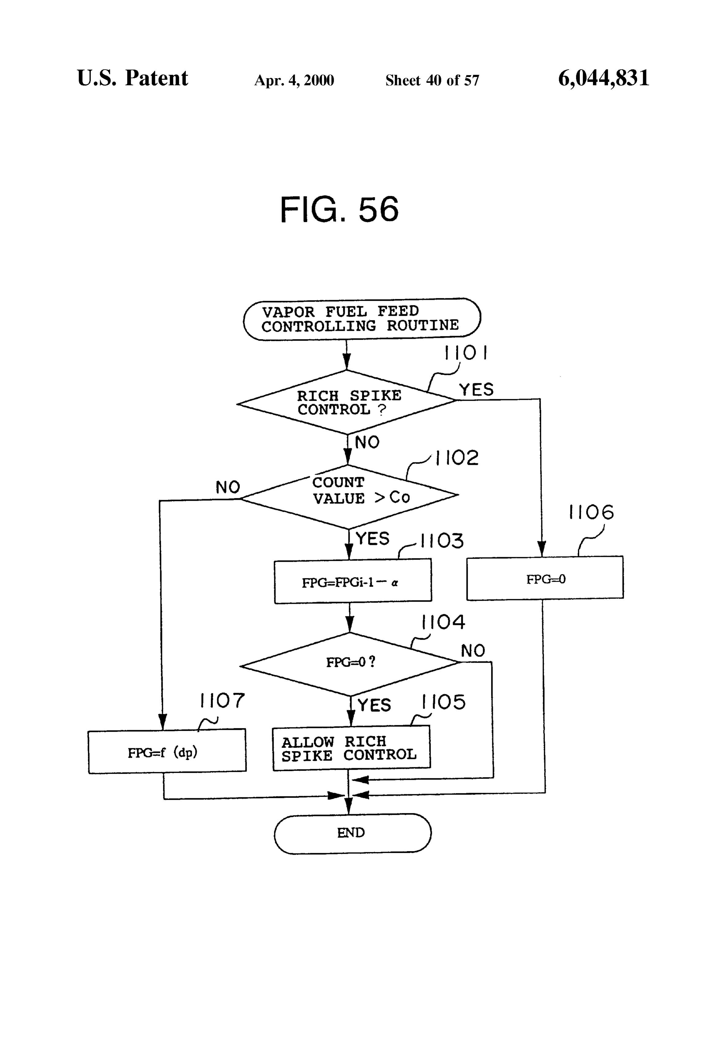
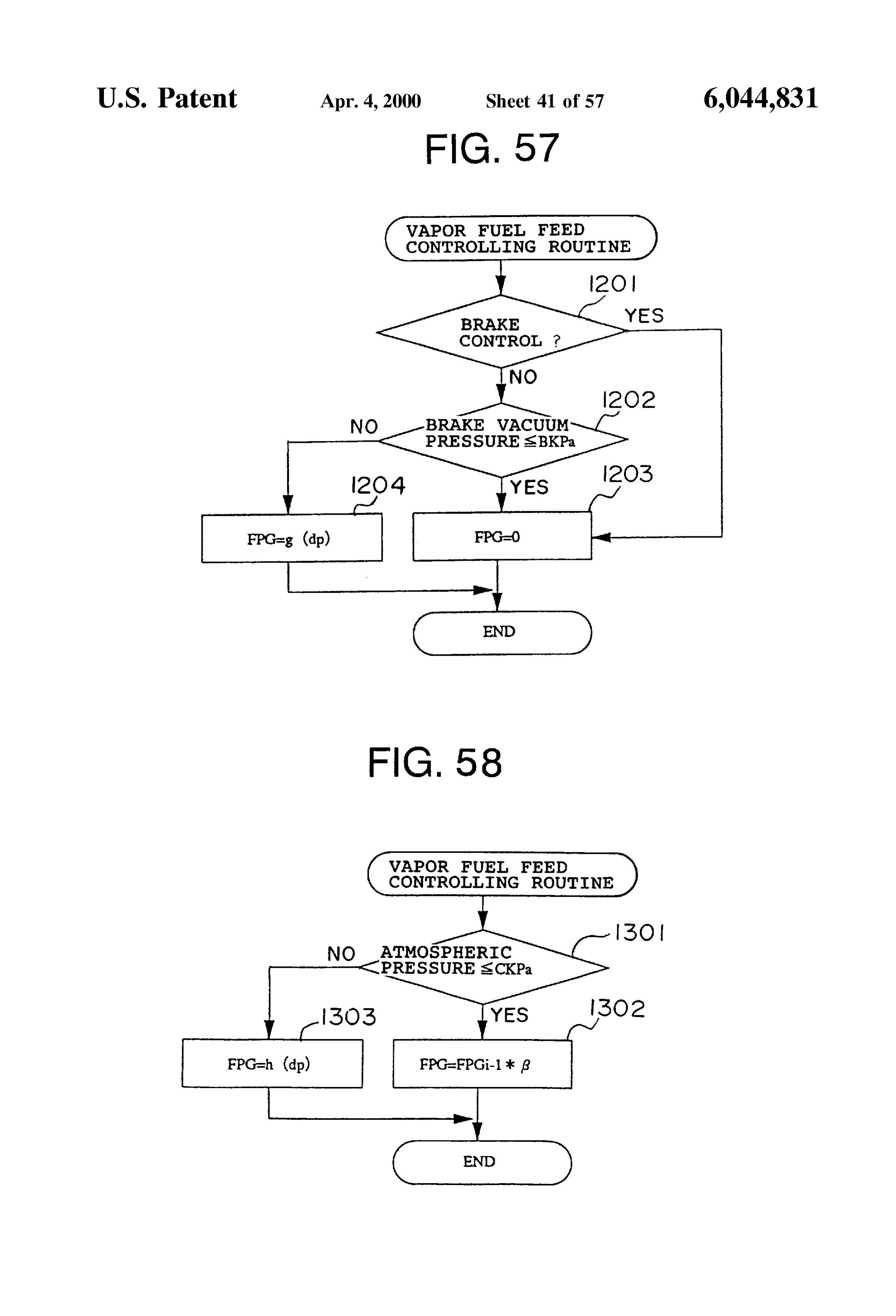
fuel Vapor amount and the fuel injection amount from the FIG.24 is a map for determining a relative relation among torque variation and the torque variation change. By this 65 a throttle Valve opening degree TA, a fuel vapor amount compensation, it is possible to prevent the rich misfire compensation amount FPG and an engine revolution speed caused by the purge with a more precision. NE;
Page 65
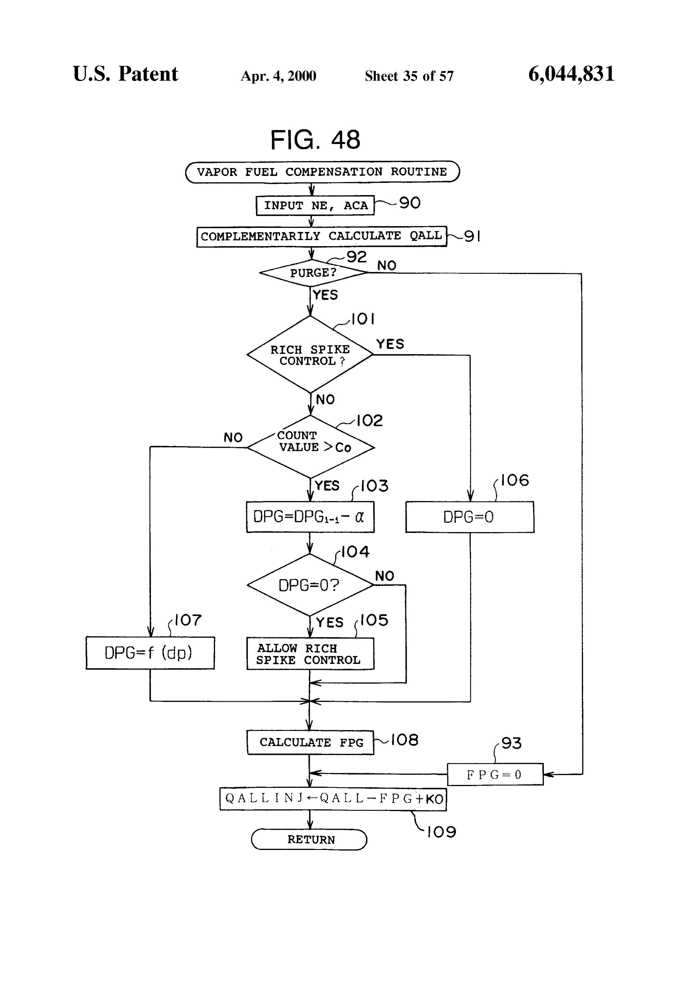
FIG. 25 is a map for determining a relationship between FIG. 48 is a flowchart showing a “fuel vapor feed con the fuel vapor amount compensation amount FPG and the trolling routine” executed by the ECU;
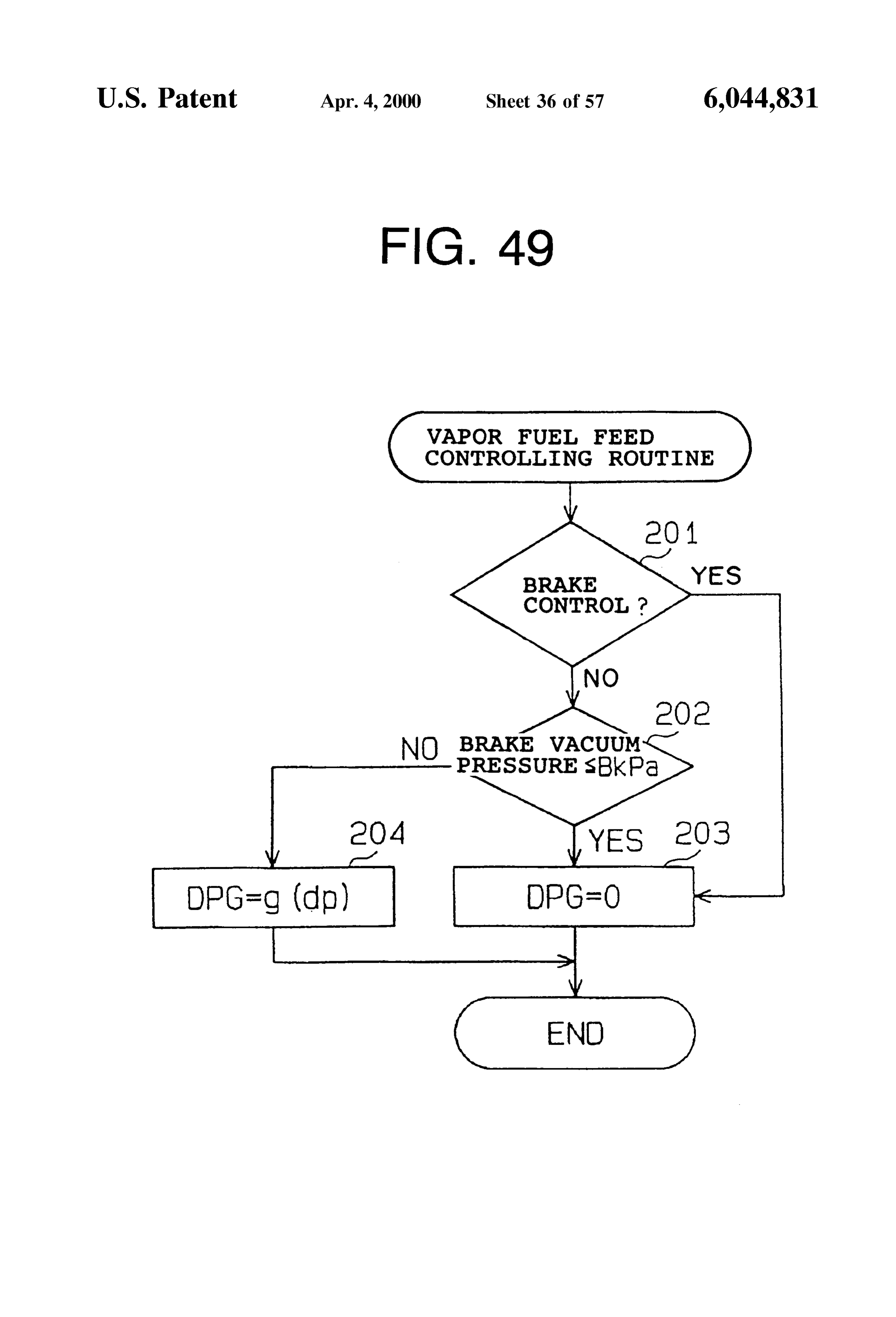
purge gas amount Qp, FIG. 49 is another flowchart showing a “fuel vapor feed FIG. 26 is a map for determining a relationship between controlling routine';
the fuel vapor amount compensation amount FPG and the FIG. 50 is still another flowchart showing a “fuel vapor difference between the atmospheric pressure and the intake feed controlling routine';
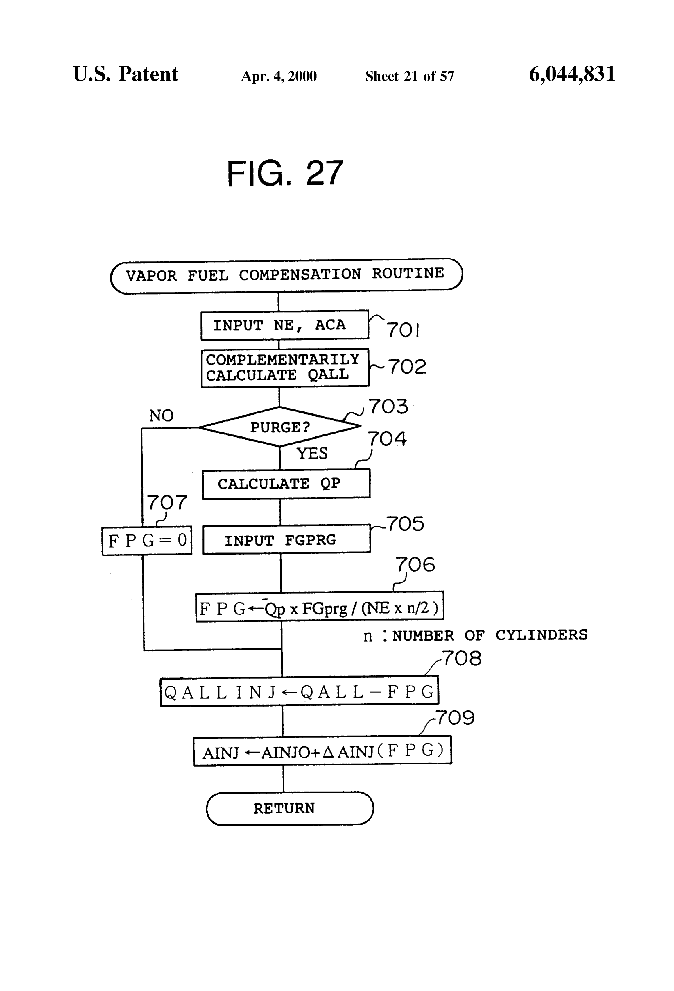
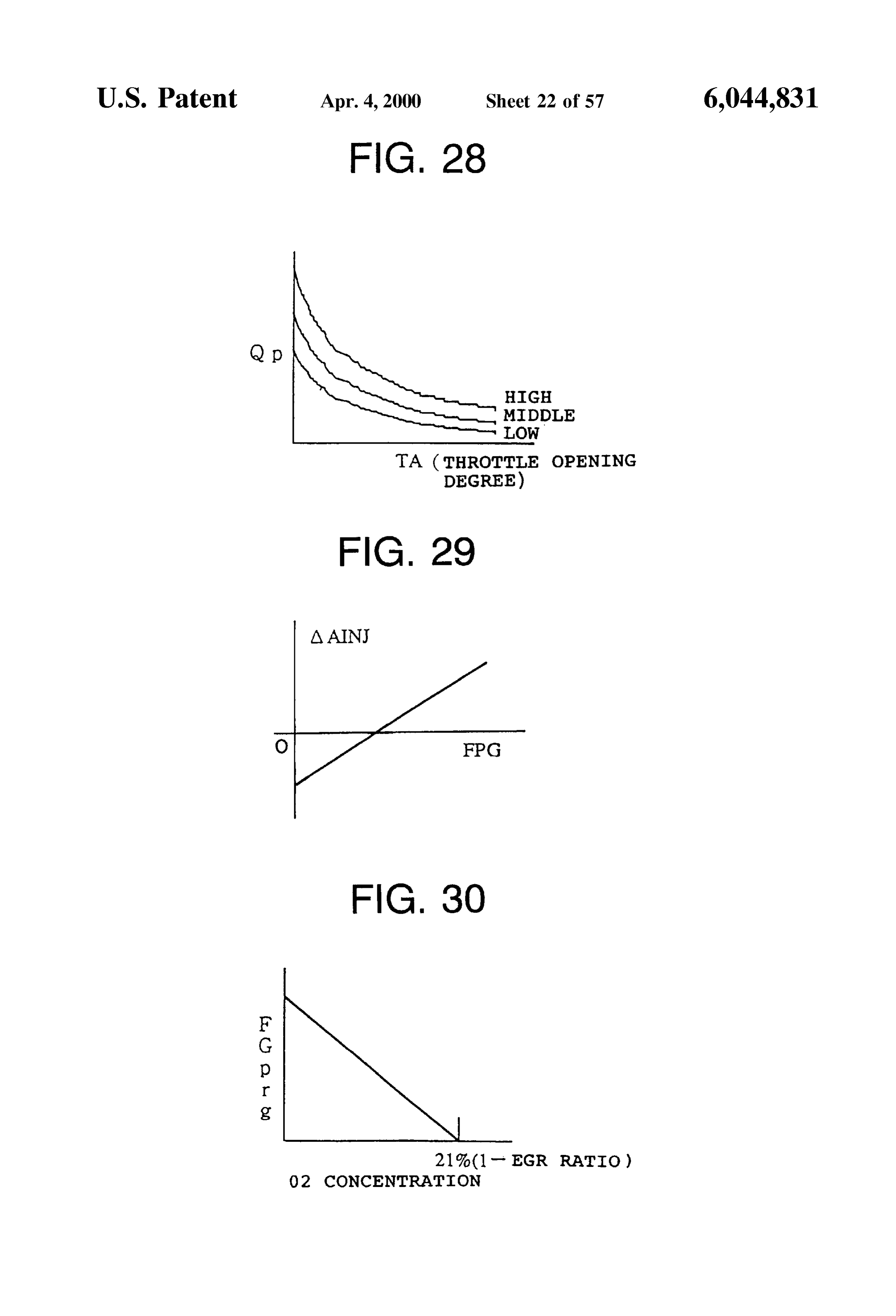
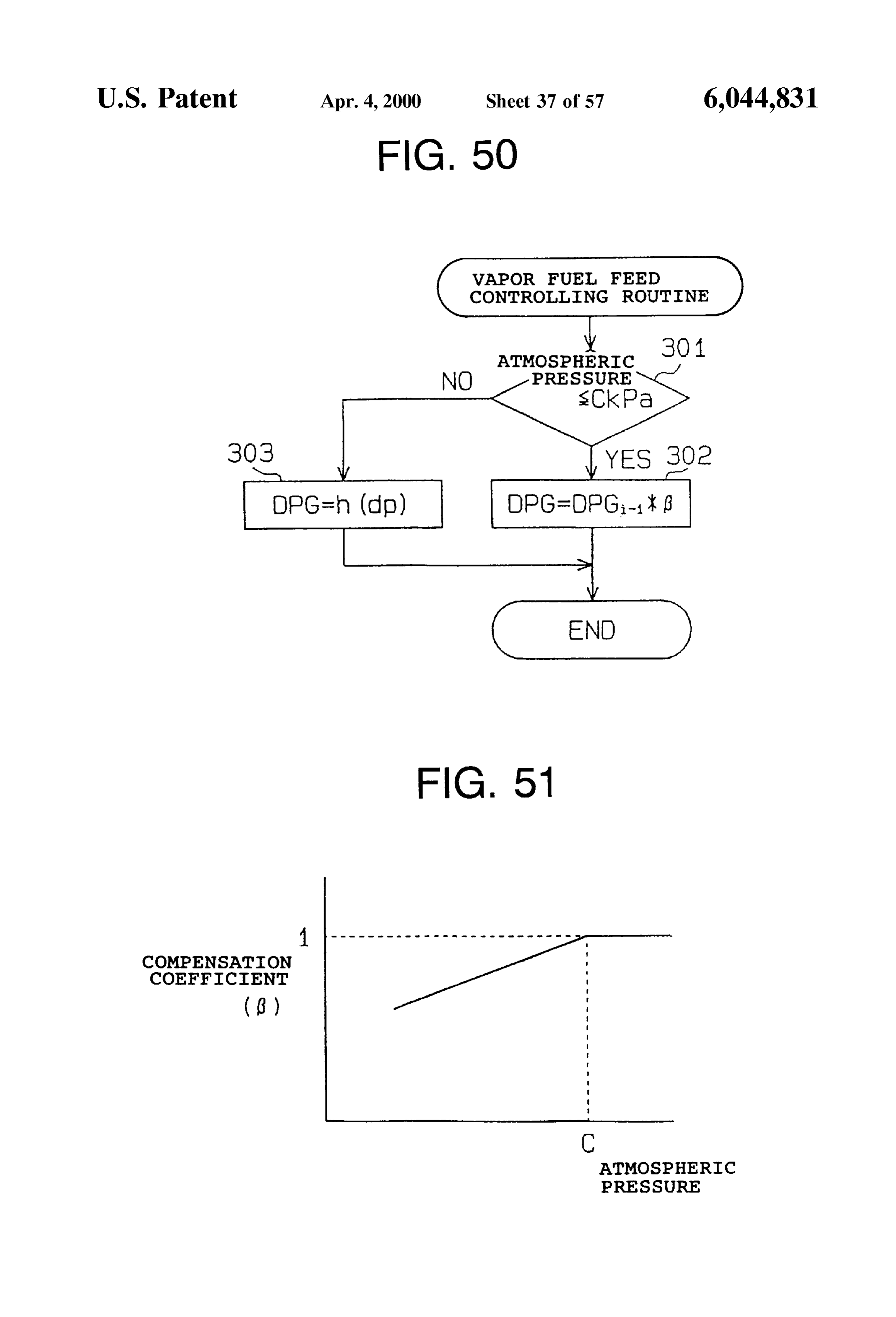
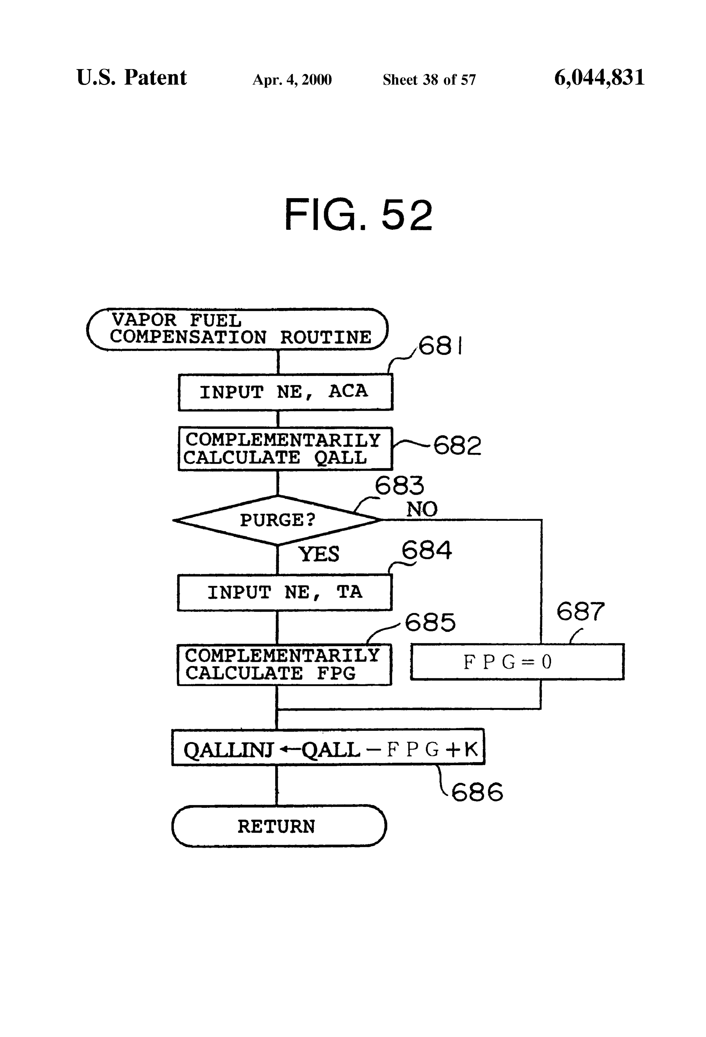
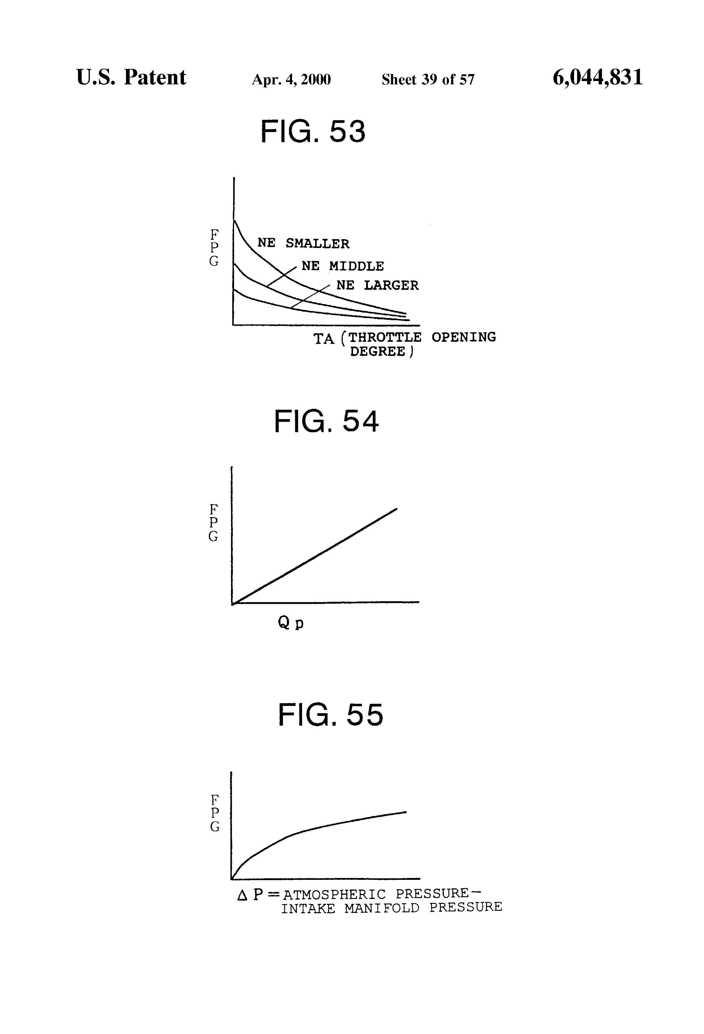
manifold preSSure, FIG. 51 is a map showing a relationship between the FIG. 27 is a flowchart showing an example for controlling atmospheric pressure and the compensation coefficient; the fuel injection timing in response to the fuel Vapor amount 1O FIG. 52 is a flowchart showing a compensation control compensation amount FPG; example of the fuel vapor amount; FIG. 28 is a map showing a relationship among the purge FIG. 53 is a map for determining a relative relation among gas amount Qp, the throttle valve opening degree TA and the a throttle Valve opening degree TA, a fuel vapor amount engine revolution Speed; compensation amount FPG and an engine revolution speed FIG. 29 is a map showing a relationship between the 15 NE;
change amount AAINJ of the fuel injection timing and the FIG. 54 is a map for determining a relationship between fuel vapor amount; the fuel vapor amount compensation amount FPG and the FIG. 30 is a map for detecting a concentration of the fuel purge gas amount Qp,
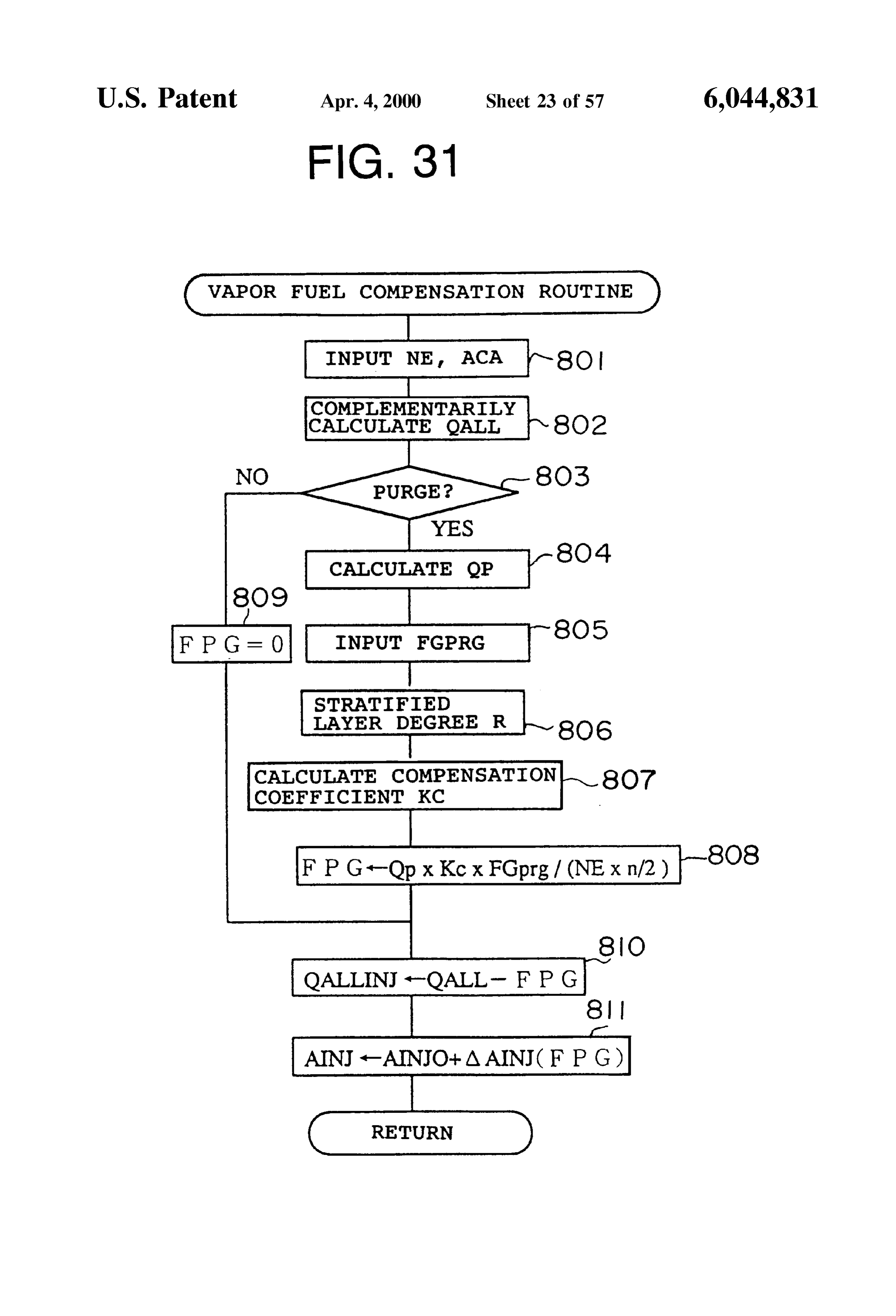
Vapor, FIG. 55 is a map for determining a relationship between FIG. 31 is a flowchart showing an example for compen the fuel vapor amount compensation amount FPG and the Sating for the fuel vapor amount in response to the combus difference between the atmospheric pressure and the intake tion condition (degree of Stratified combustion); manifold preSSure,
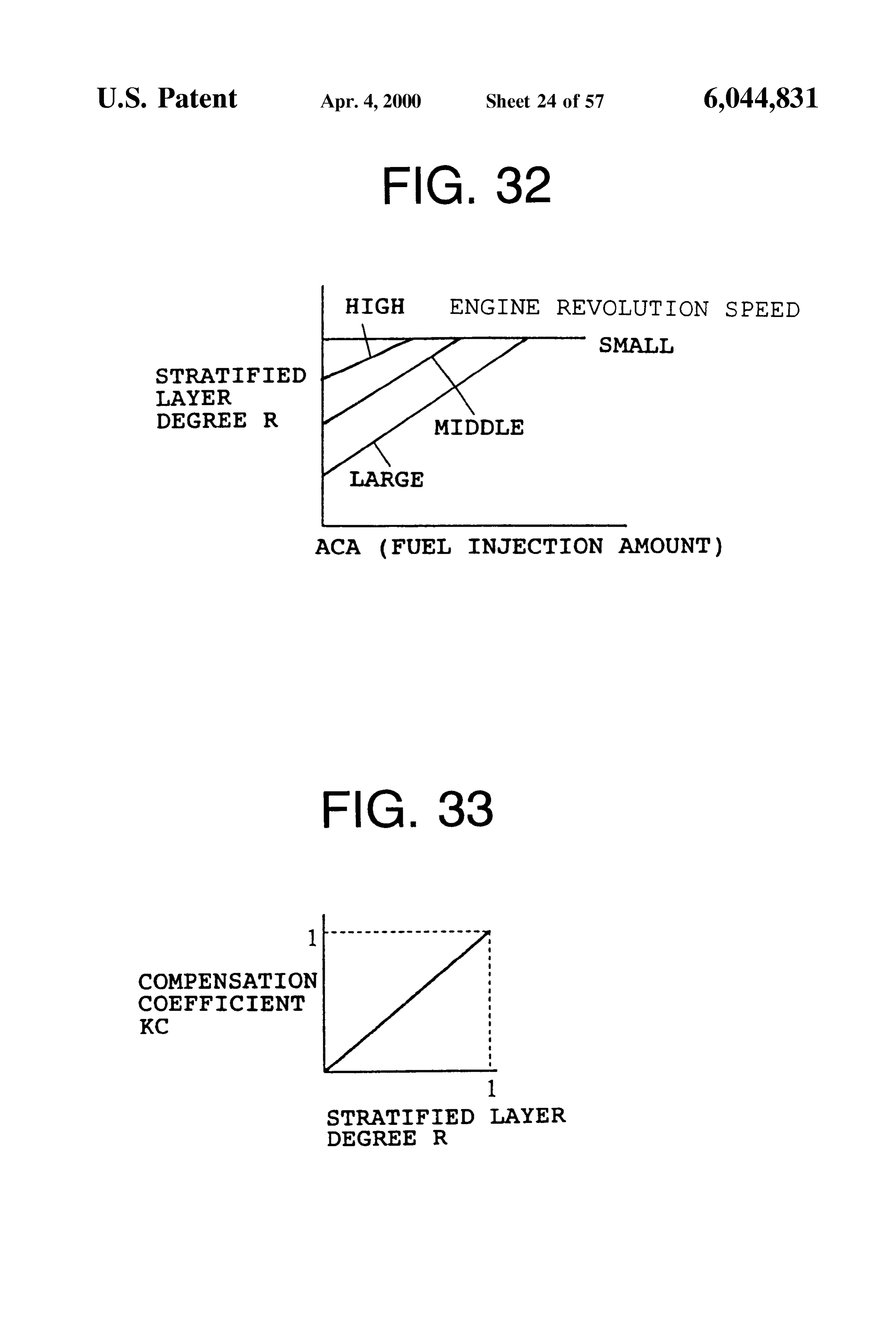
FIG. 32 is a map showing a relationship among a degree FIG. 56 is a flowchart showing a “fuel vapor feed con of Stratification, an accelerator opening degree (or fuel trolling routing” according to another embodiment of the injection amount) and an engine revolution speed; 25 invention;
FIG. 33 is a map showing a relationship between the FIG. 57 is a flowchart showing a “fuel vapor feed con Stratified combustion degree and the compensation coeffi trolling routing” according to Still another embodiment of cient; the invention;
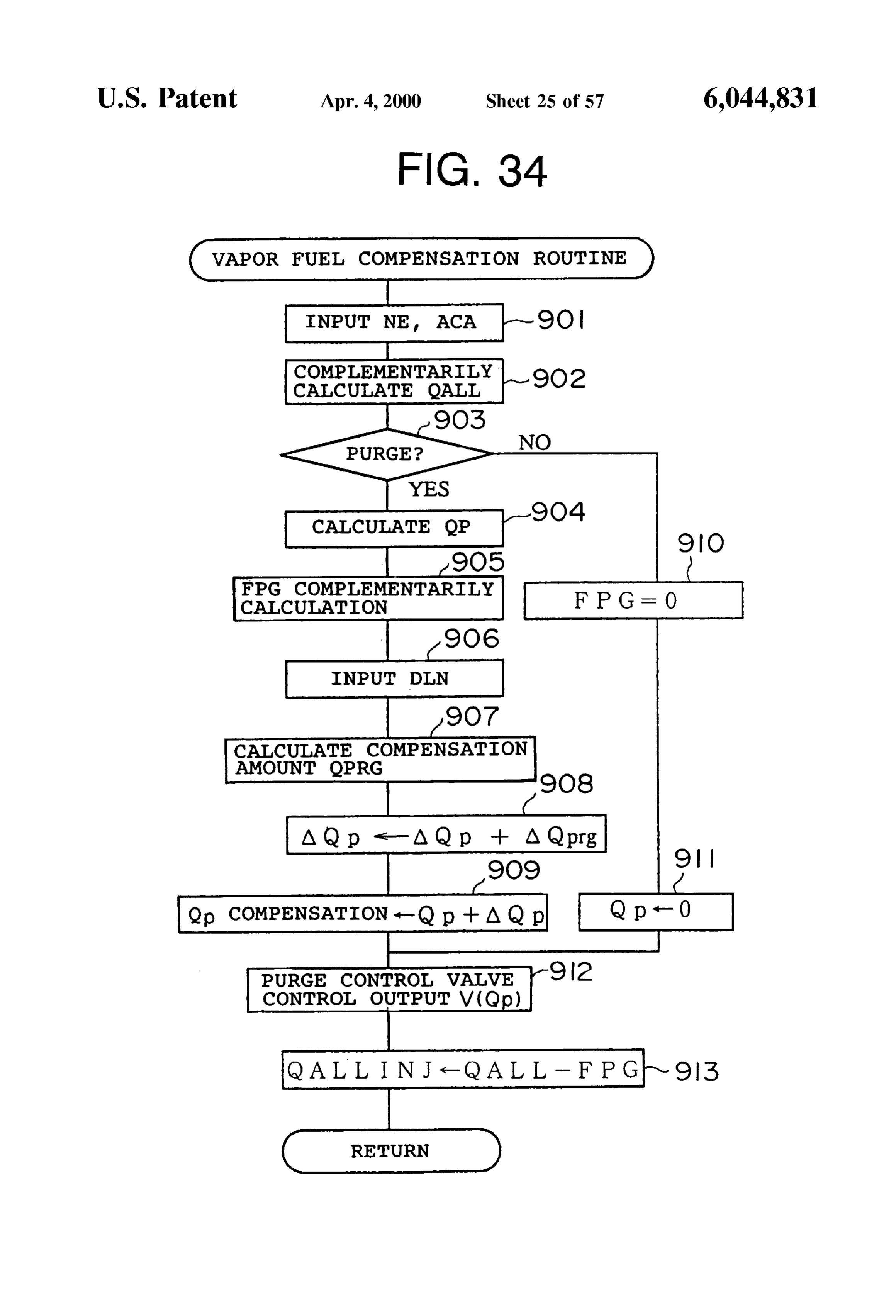
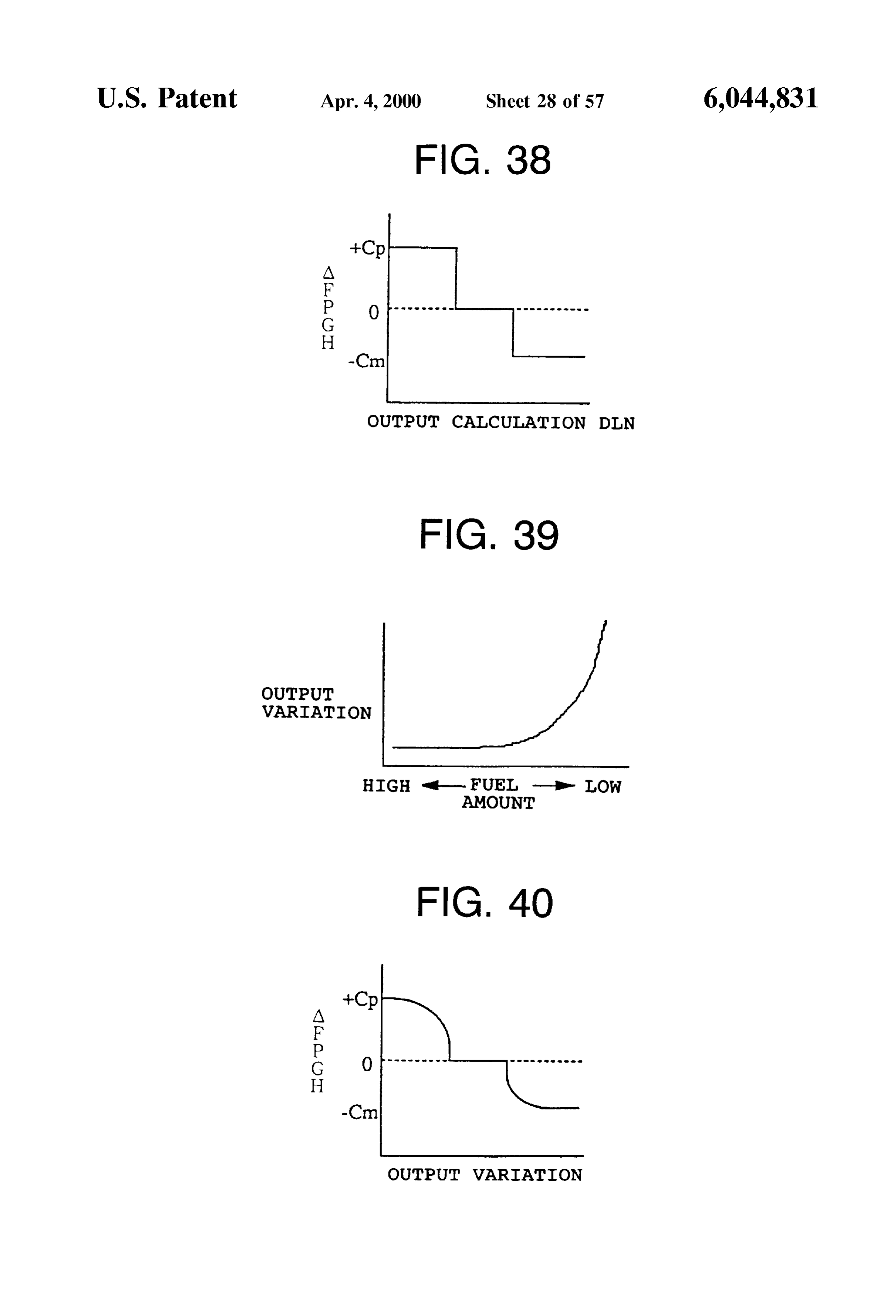
FIG.34 is a flowchart showing an example for controlling FIG. 58 is a flowchart showing a “fuel vapor feed con the purge gas amount Op in response to the output variation; trolling routing” according to Still another embodiment of FIG. 35 is a map showing a relationship between the the invention;
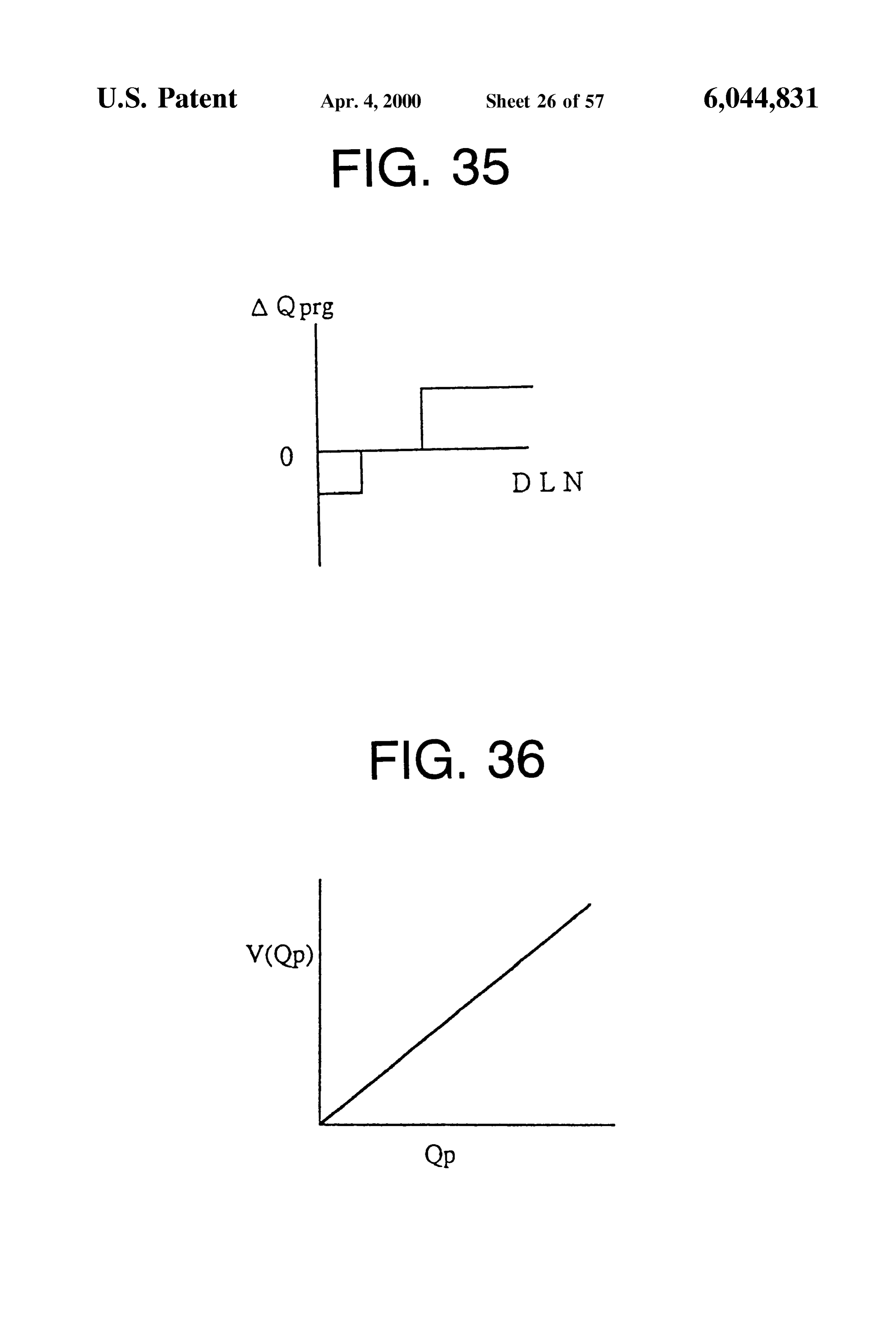
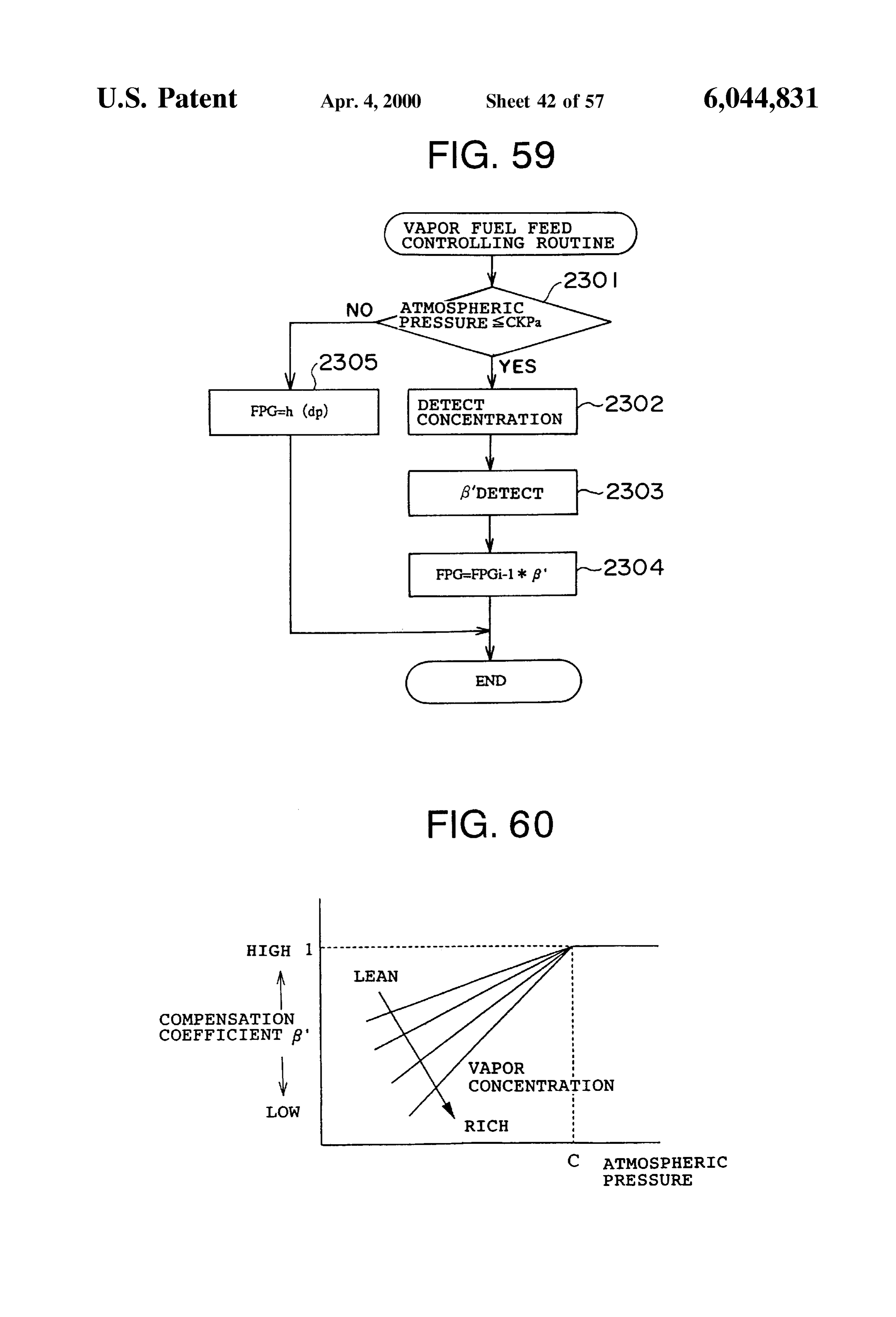
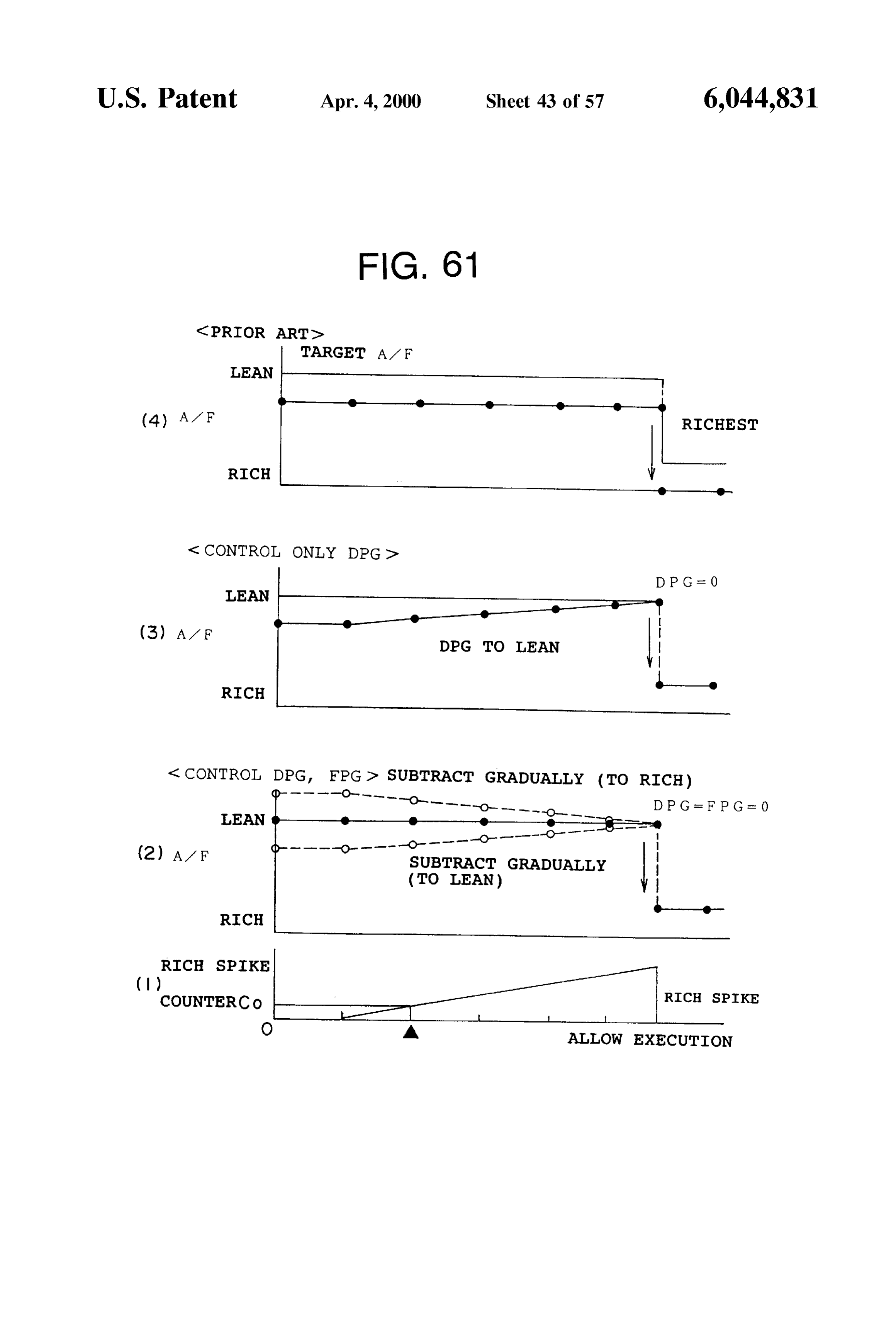
output variation and the purge gas compensation amount FIG. 59 is a flowchart showing a “fuel vapor feed con AOprg, trolling routing” according to Still another embodiment of FIG. 36 is a map showing a relationship between the 35 the invention;
purge gas amount Op and the purge control valve controlling FIG. 60 is a map showing a relationship between the output V (Qp); atmospheric pressure a nd the compensation coefficient FIG. 37 is a flowchart showing an example for compen relative to the vapor concentration;
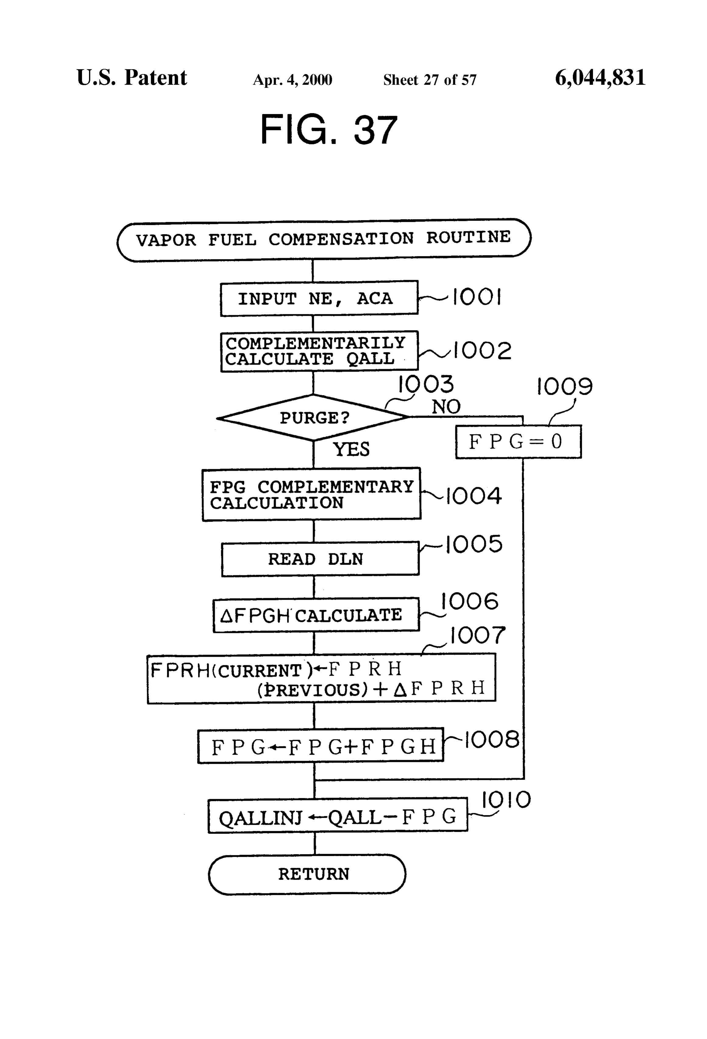
Sating the fuel vapor amount in response to the output FIGS. 61(1) to 61(4) are timing charts showing a rela variation; 40 tionship between the rich Spike control and the purge con FIG. 38 is a map showing a relationship between the trol;
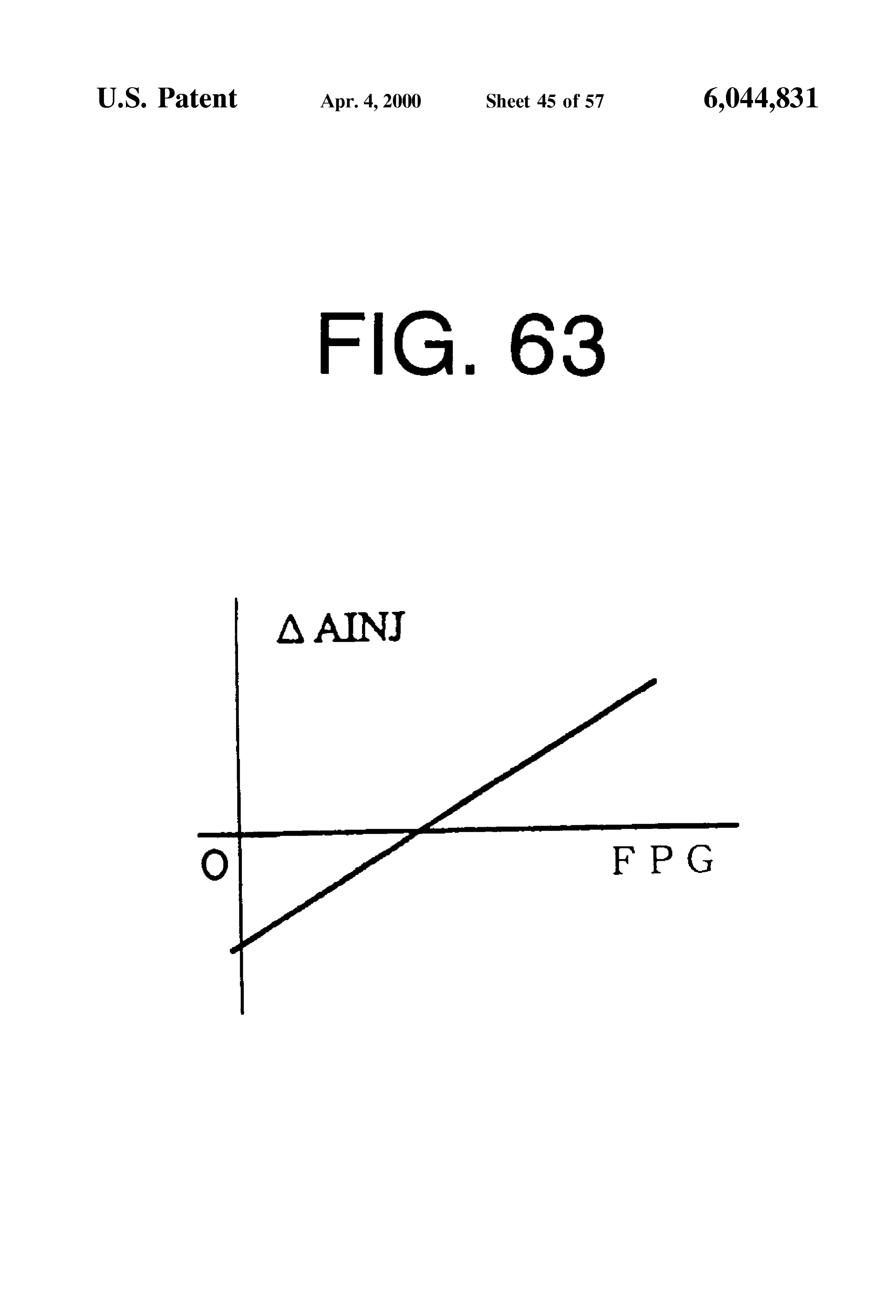
output variation and a fuel vapor amount compensation FIG. 62 is a flowchart showing a “fuel vapor feed con amount AFPGH; trolling routing” according to Still another embodiment of FIG. 39 is a map showing a relationship between the the invention;
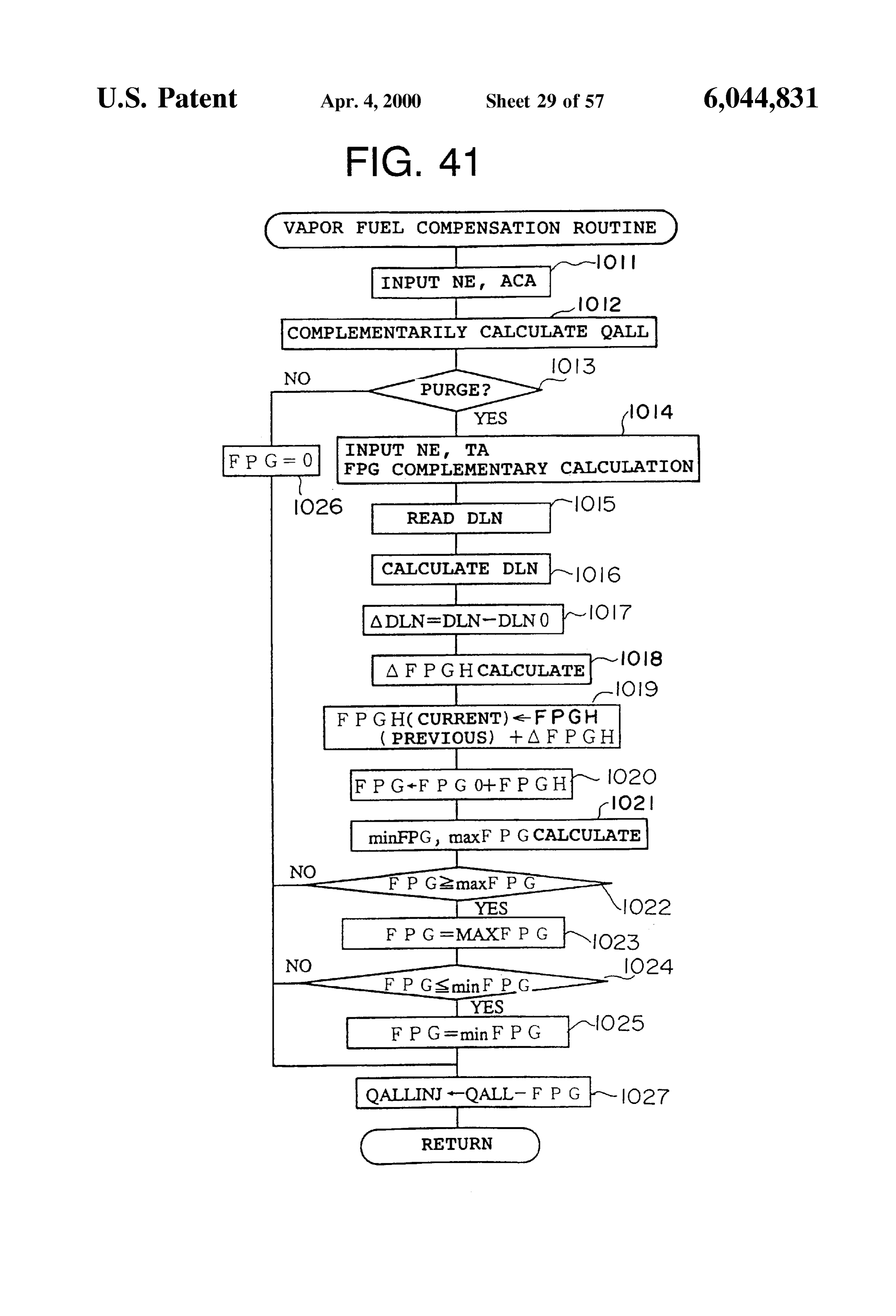
output variation and the fuel amount; 45 FIG. 63 is a map showing a relationship between the FIG. 40 is an example of a map showing a relationship change amount AAINJ of the fuel injection timing and the between the output variation and the fuel vapor amount fuel vapor amount compensation amount FPG; compensation amount AFPGH; FIG. 64 is a conceptional Structural view concerning the FIG. 41 is a flowchart showing an example in which the 50 fifth feature;
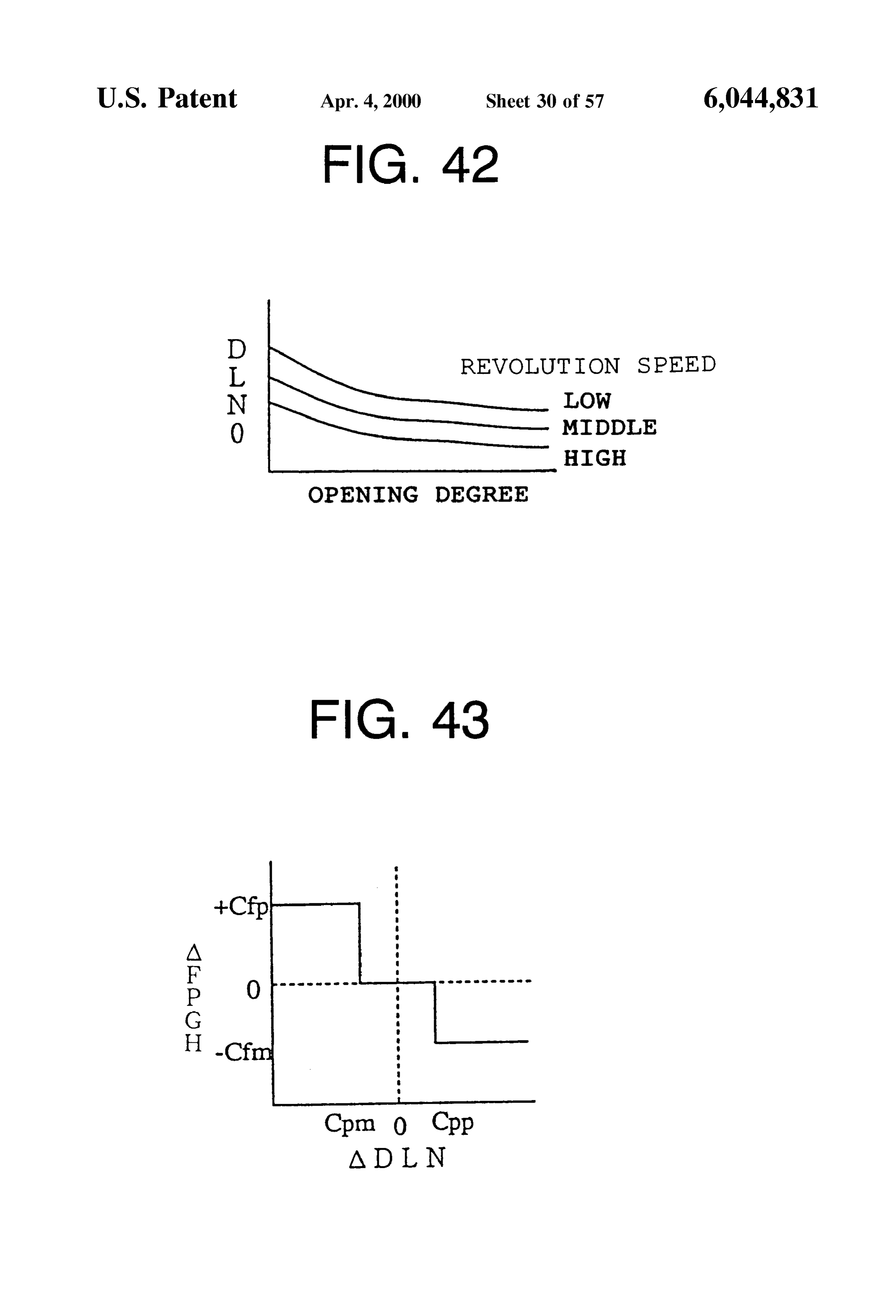
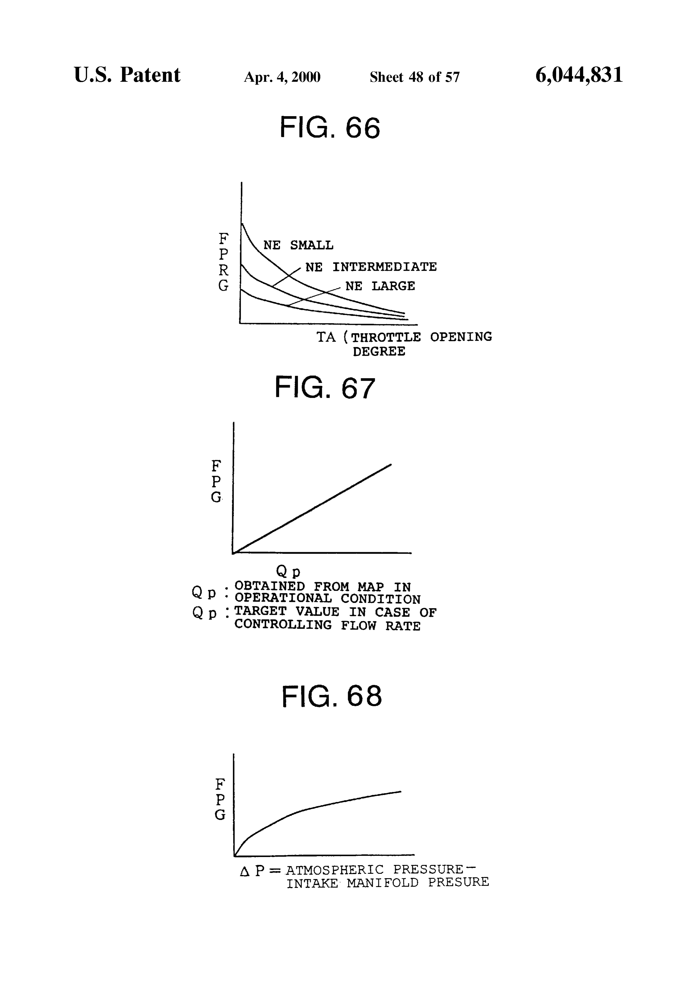
fuel vapor amount is compensated for in response to the FIG. 65 is a flowchart showing an example of the com output variation and a guard process is effected; pensation control of the fuel vapor amount; FIG. 42 is a map showing a relationship among the FIG. 66 is a map showing a relationship among the reference output variation DLN0, the accelerator opening throttle valve opening degree TA, the fuel vapor amount degree and the engine revolution Speed; 55 -compensation amount FPG and the engine revolution FIG. 43 is a map showing a relationship between the speed NE;
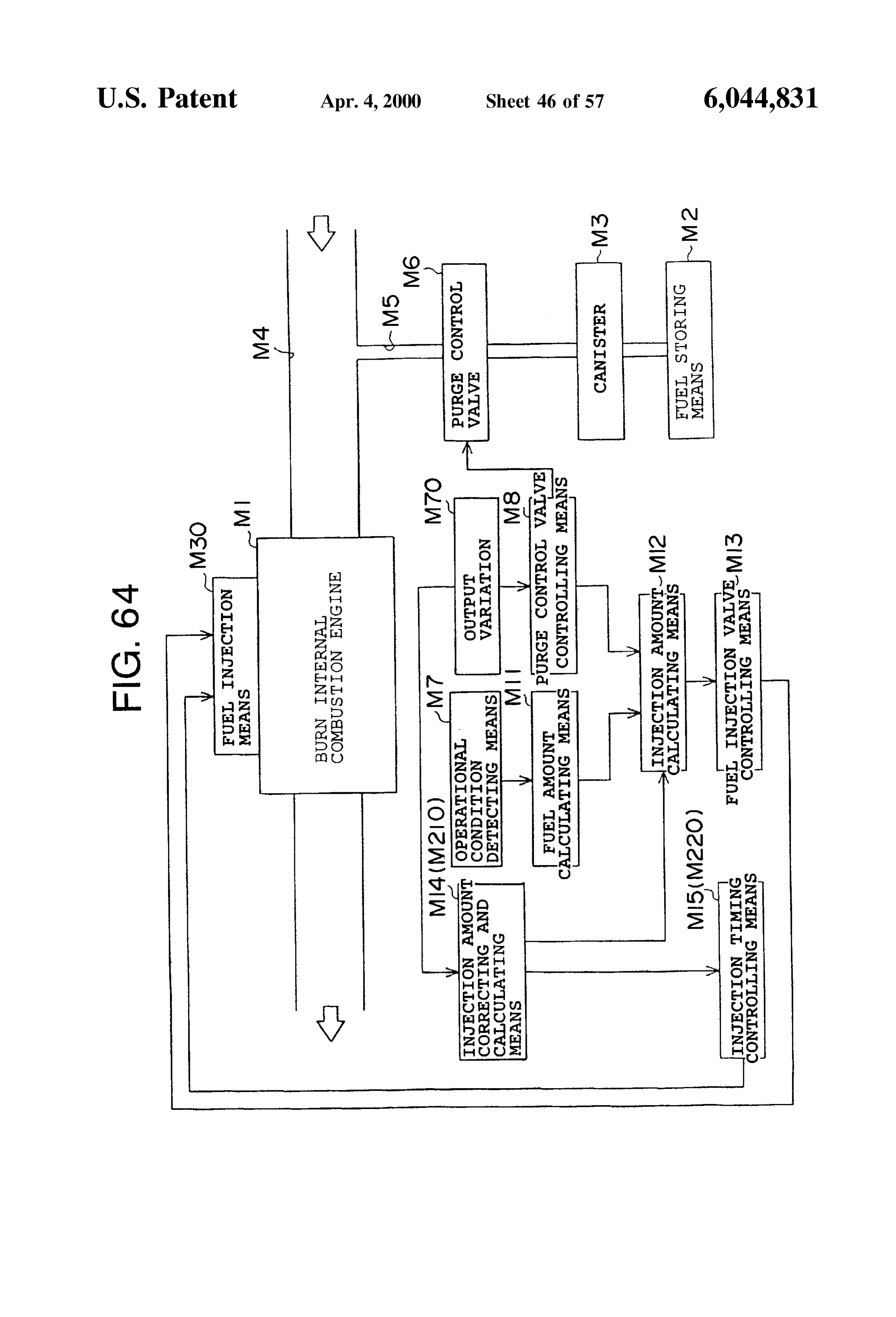
change amount ADLN of the output variation and the fuel FIG. 67 is a map showing a relationship between the fuel vapor amount compensation amount AFPGH; Vapor amount compensation amount FPG and the purge gas FIG. 44 is a conceptional structural view showing a fifth amount Op;
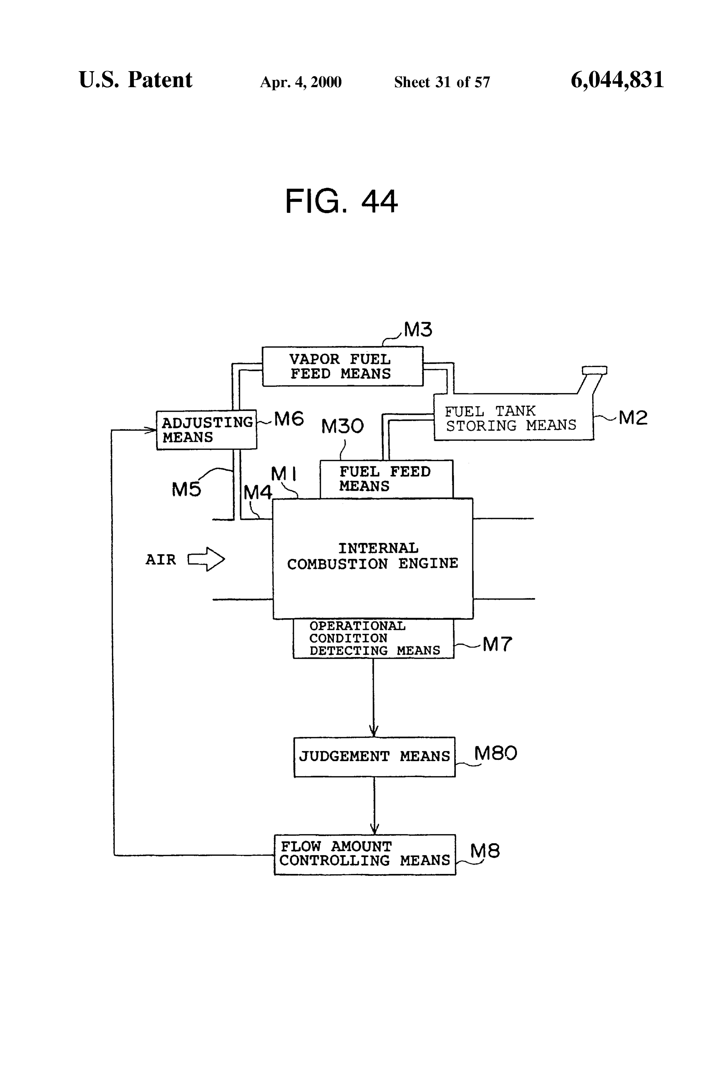
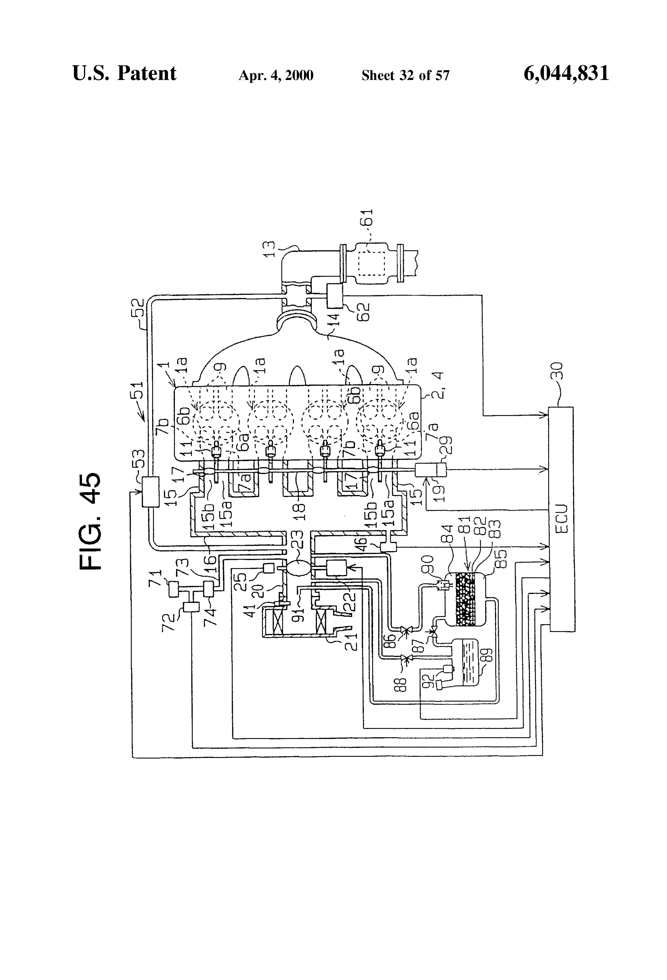
feature of the invention; 60 FIG. 68 is a map for determining a relationship between FIG. 45 is a schematic structural view showing a fuel the fuel vapor amount compensation amount FPG and the Vapor feed controlling apparatus for a sleeve interior injec difference between the atmospheric pressure and the intake tion engine in an embodiment of the invention; manifold preSSure,
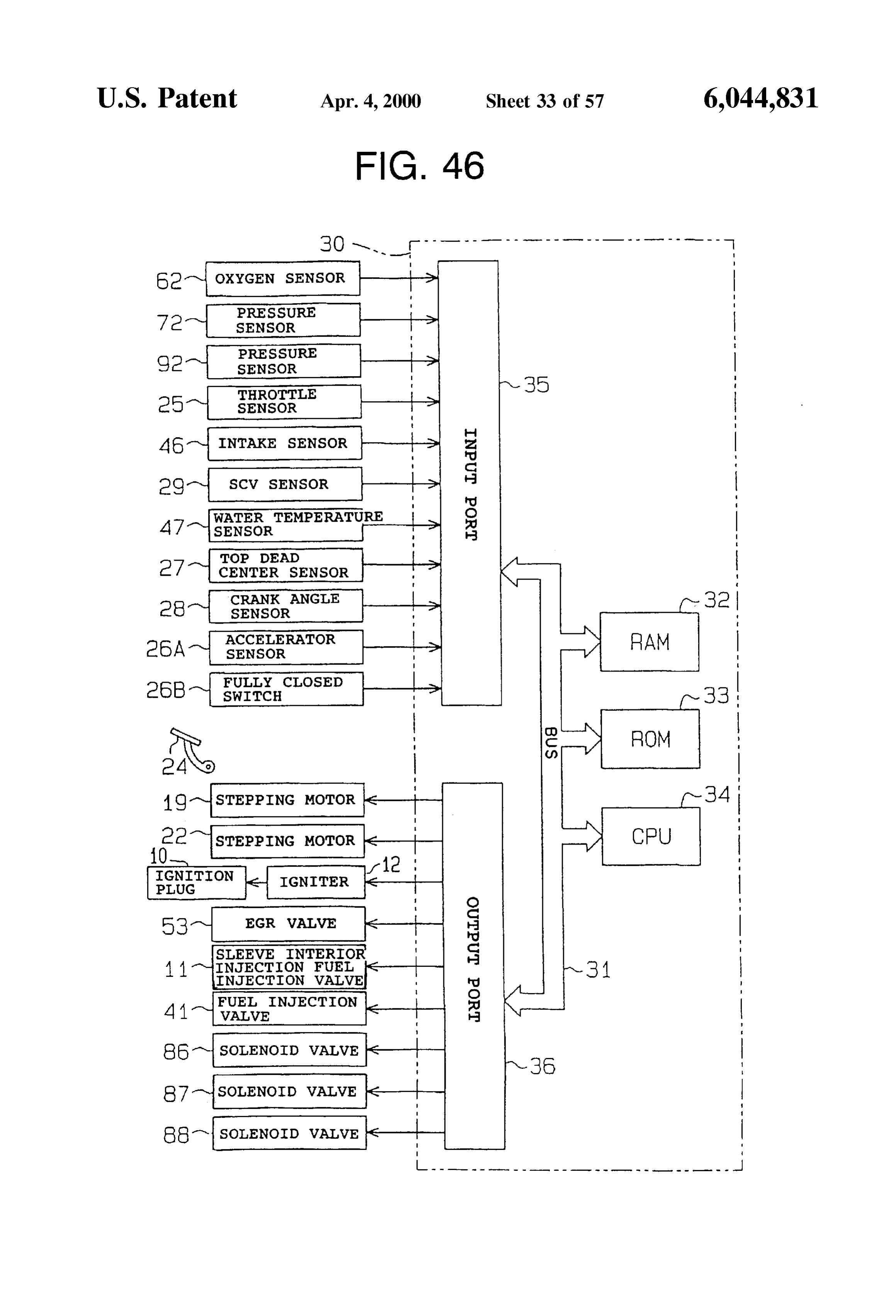
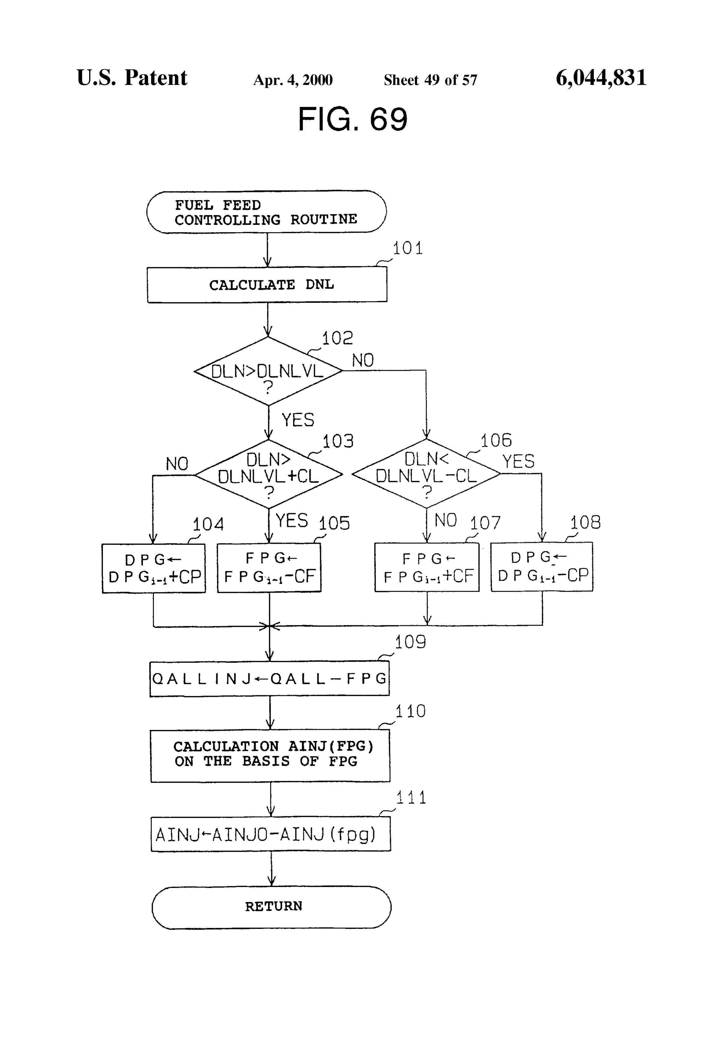
FIG. 46 is a block diagram showing an electric structure FIG. 69 is a flowchart showing a “fuel feed controlling of an ECU; 65 routine” executed by the ECU;
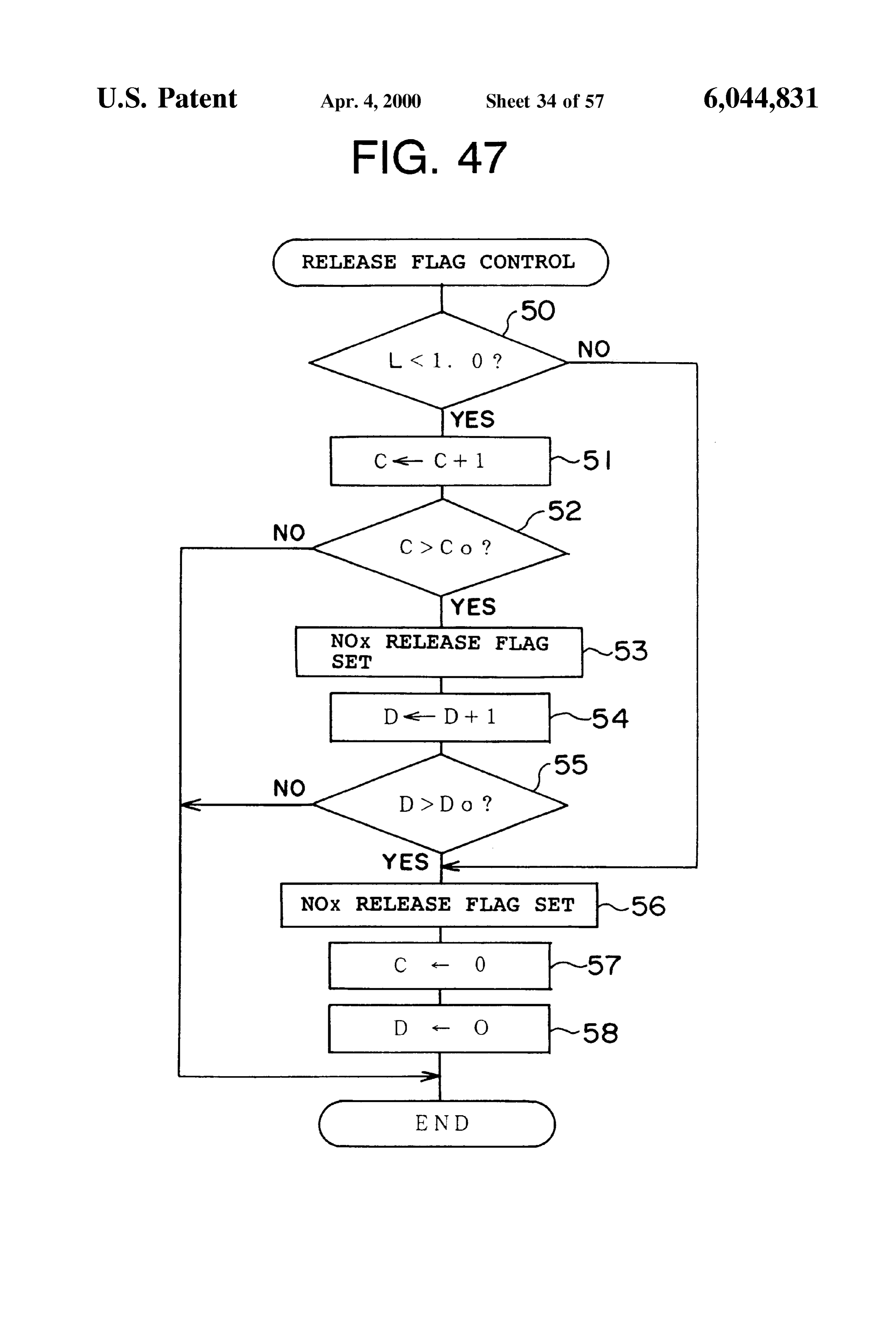
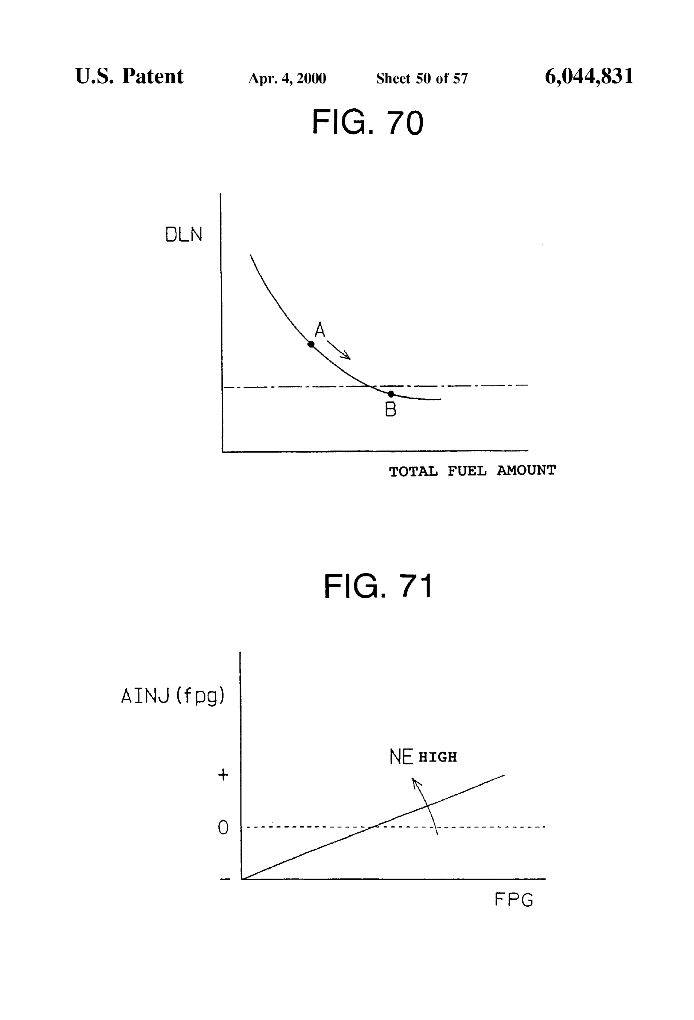
FIG. 47 is a flowchart showing an example of a control FIG. 70 is a graph showing a relationship of the torque routine of an NOx release flag; variation relative to the total fuel addition amount;
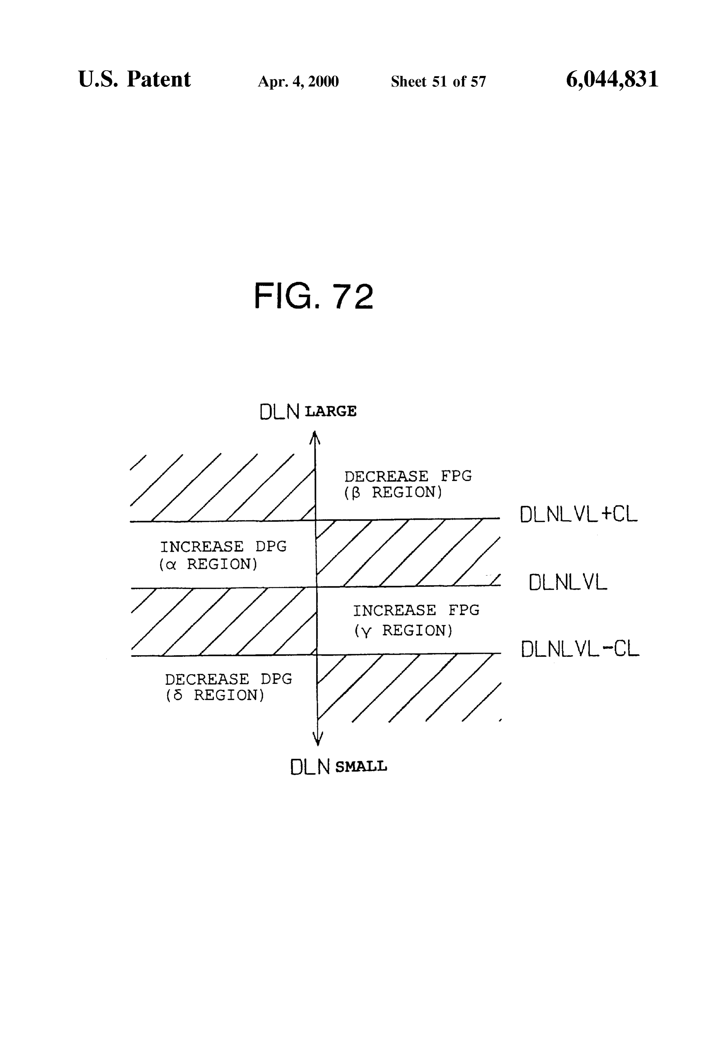
Page 66
FIG. 71 is a map showing a relationship of the injection (1) First Compensation Means timing item relative to the fuel vapor compensation amount; A first compensation means is a compensation means for FIG. 72 is a diagram showing the control contents Set in compensating for the fuel vapor amount So that the engine response to the value of the torque variation relative to the revolution Speed of the internal combustion engine is iden target torque variation; tical with the target Revolution Speed. FIG. 73 is a schematic view showing a relation or the like (2) Second Compensation Means of the fuel amount in the case where the Swirl is generated A Second compensation means is a compensation means for compensating for the fuel vapor amount in response to along the line F-F" and the behavior of the fuel around the the engine revolution Speed of the internal combustion Spark plug; engine.
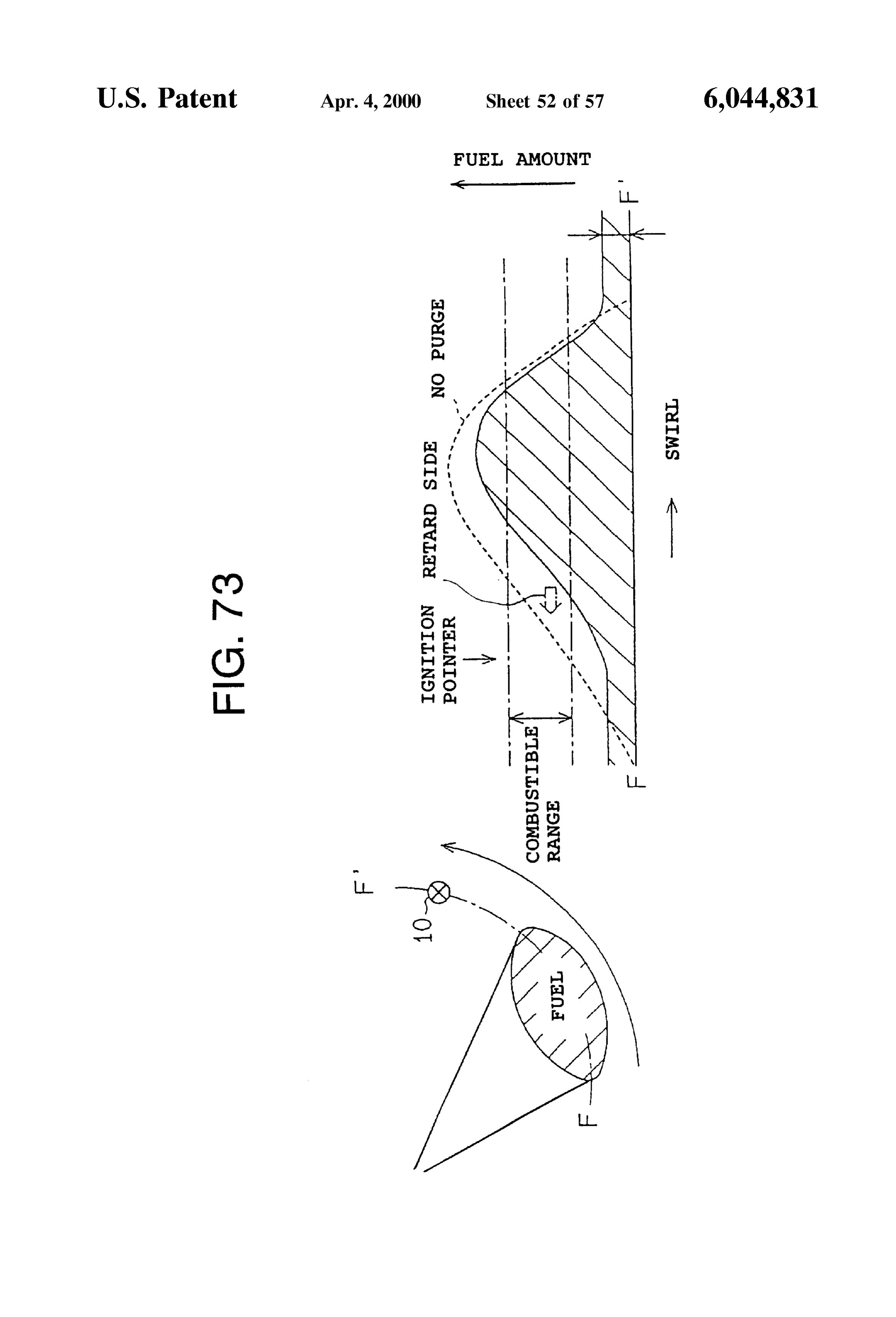
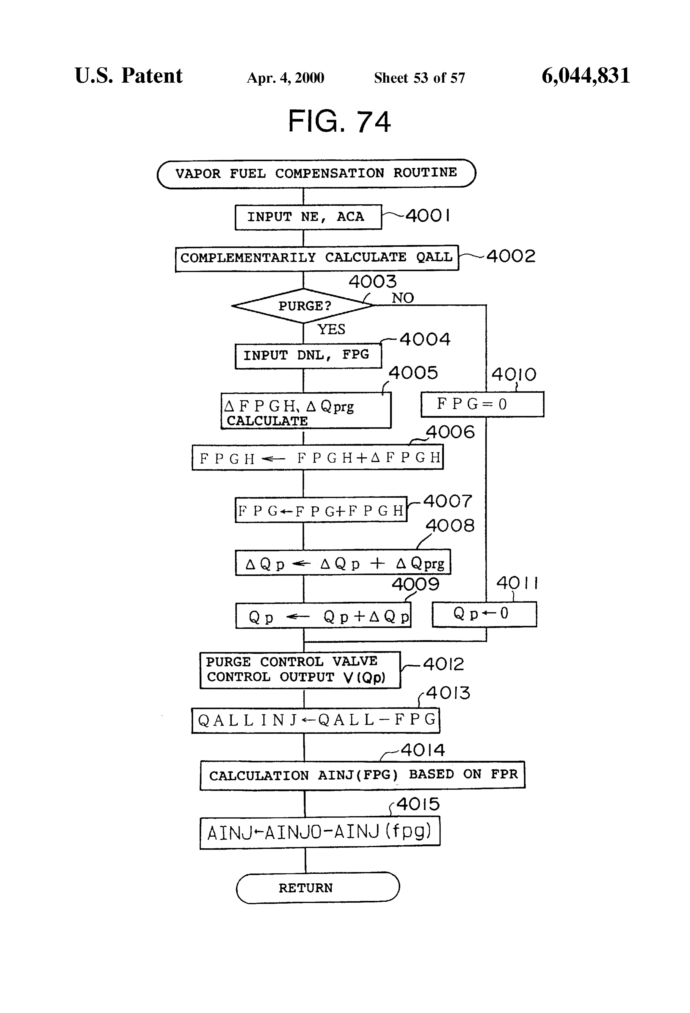
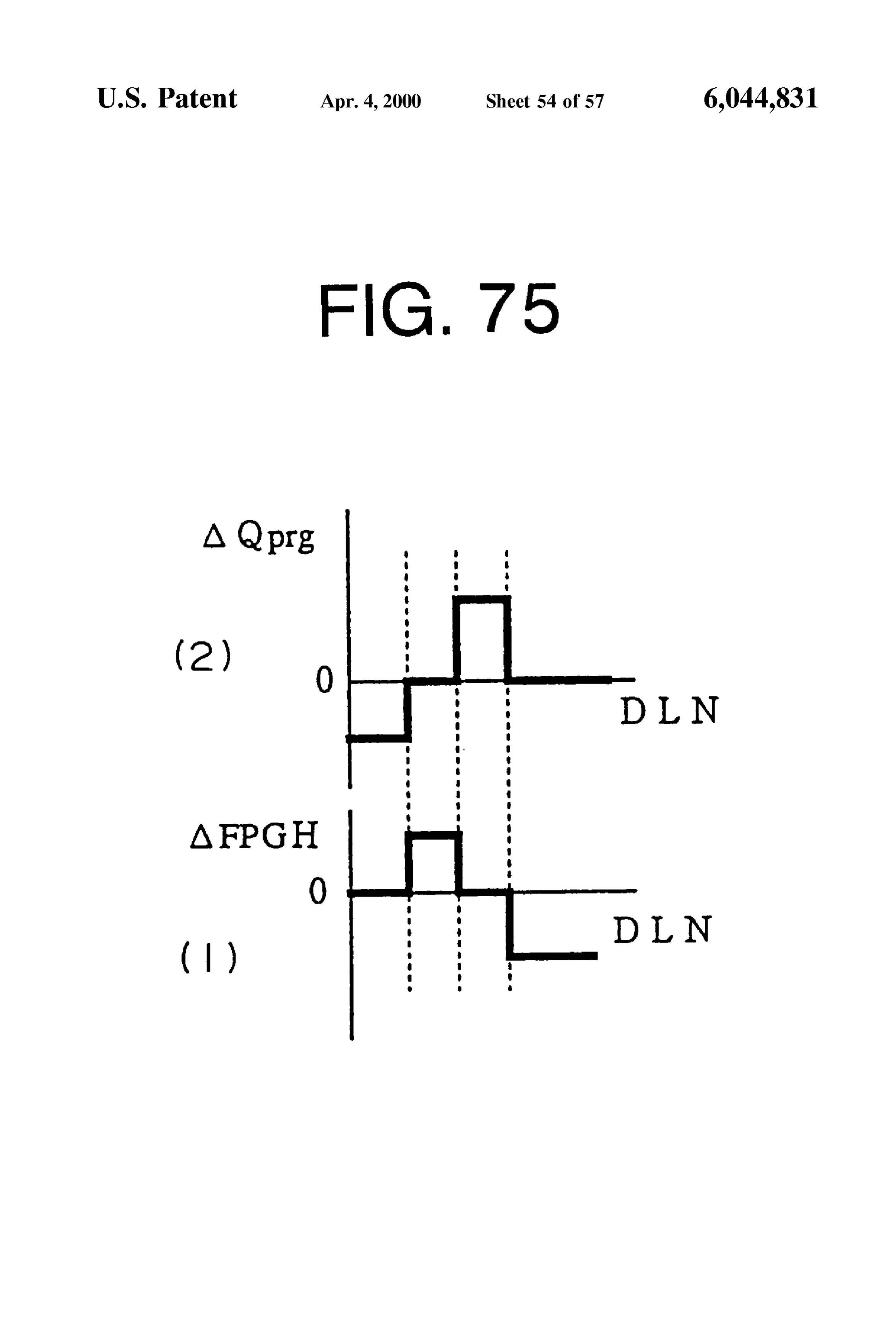
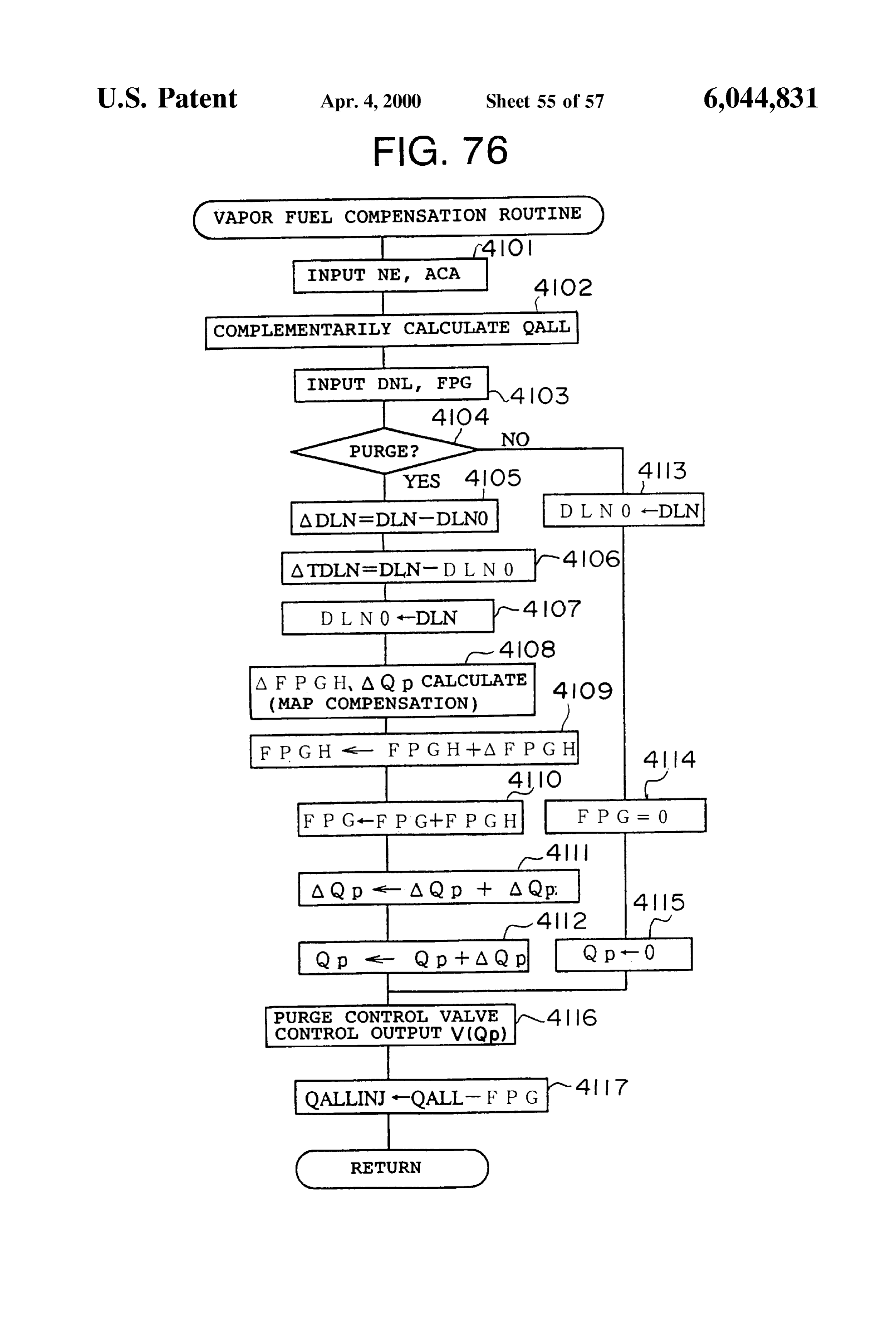
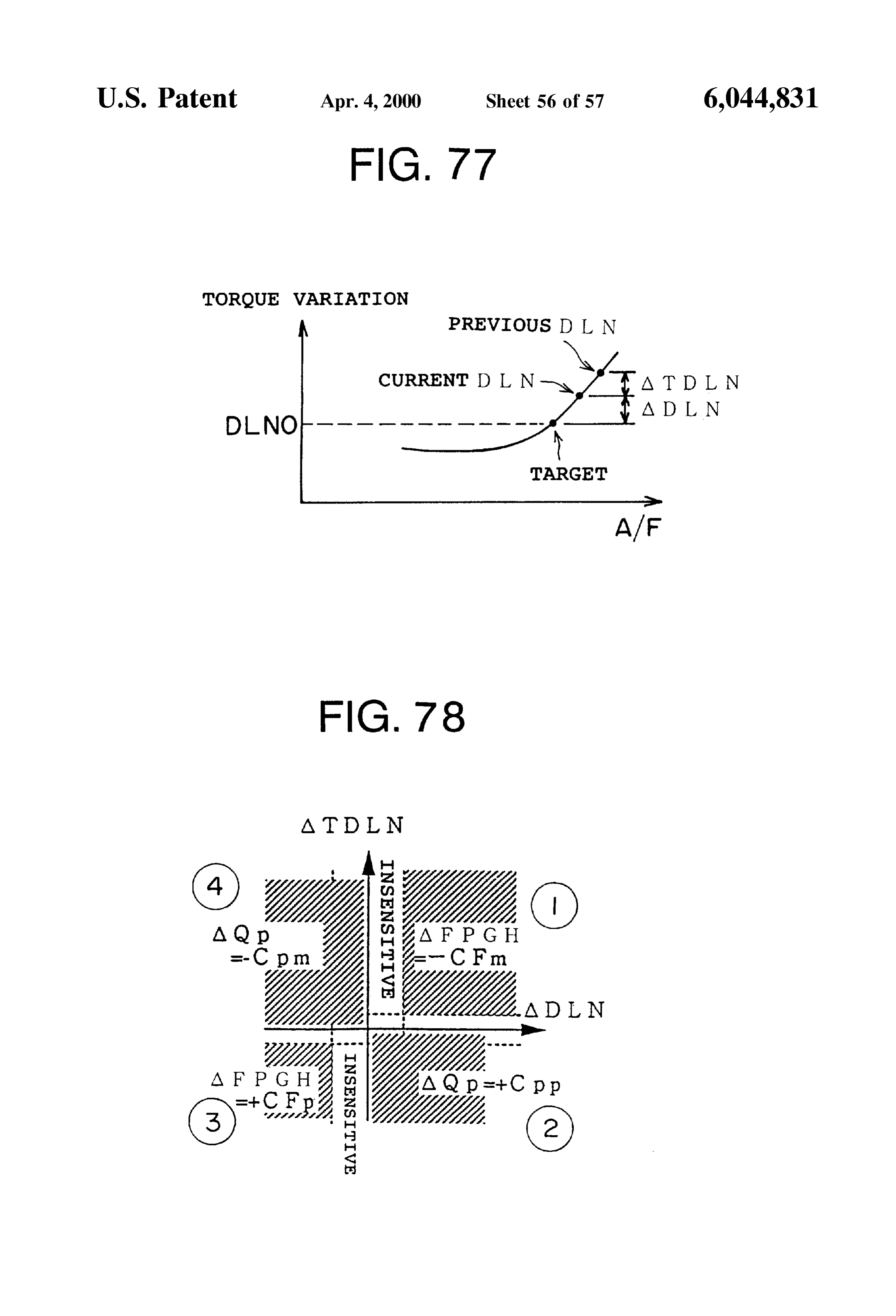
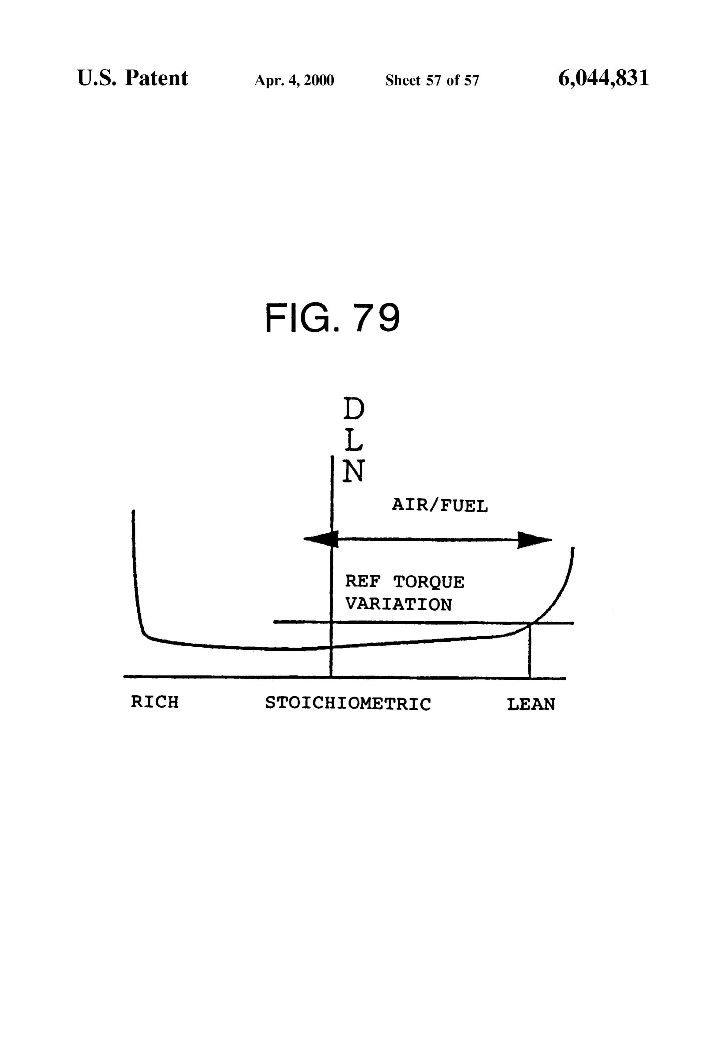
FIG. 74 is a flowchart showing another embodiment; (3) Third Compensation Means FIG. 75(1) is a map showing a relationship between DLN A third compensation means is a compensation means for and AQprg, and FIG. 75(2) is a map showing a relationship compensating for the fuel vapor amount in response to the between DLN and a fuel vapor amount compensation output variation of the internal combustion engine. amount AFPRFGH; 15 (4) Fourth Compensation Means FIG. 76 is a flowchart of another embodiment; A fourth compensation means is a compensation means FIG. 77 is a map for determining the relationship among for compensating for the fuel vapor amount in response to the torque variation, the air/fuel ratio A/F and the target the combustion of the internal combustion engine. torque variation; (5) Fifth Compensation Means FIG. 78 is a map for determining relationships among A fifth compensation means requires the provision of a ADLN and ATDLN and AQp and AFPGH; and concentration detecting means M21 for detecting the con FIG. 79 is a graph showing a relationship between the centration of the fuel vapor as a prerequisite as shown in torque variation and the air/fuel ratio. FIG. 2. Then, the fifth compensation means compensates for
the fuel injection condition or the opening degree of the
DESCRIPTION OF THE PREFERRED purge control valve in response to the concentration of the EMBODIMENTS fuel vapor detected by the In concentration detecting means. (6) Combination of Compensation Means
An embodiment of the present invention will now be The first to fourth means are applied independently or in described in greater detail with reference to the accompa any combination according to the present invention. The nying drawings. fifth compensation means is applied in parallel with the first FIGS. 1 through 43 show embodiments embodying the to fourth compensation means according to the present first to fourth features of the present invention. invention.
FIG. 1 is a view showing an outline of the apparatus FIG. 3 is a Schematic diagram showing a fuel vapor feed according to the present invention. In FIG. 1, M1 denotes a 35 controlling means of a sleeve interior injection type engine lean burn type internal combustion engine in which a fuel mounted on a vehicle. The engine 1 is provided with, for Storing means M2 for Storing fuel for driving the lean burn example, four cylinders 1a as an internal combustion engine. type internal combustion engine M1 is provided in a vehicle A structure of each cylinder 1a is shown in FIG. 4. As shown in FIGS. 3 and 4, the engine 1 is provided with pistons body (not shown). A canister M3 for storing evaporated fuel within generated from the fuel Storing means M2 is connected to 40 a cylinder block 2 which pistons are reciprocated the fuel storing means M2. within the cylinder block 2. A cylinder head 4 is provided in an upper
A purge passage M5 is provided for communicating the chamber 5 is formed portion of the cylinder block 2. A combustion between each piston and the cylinder canister M3 and an intake system M4 of the internal com head 4.
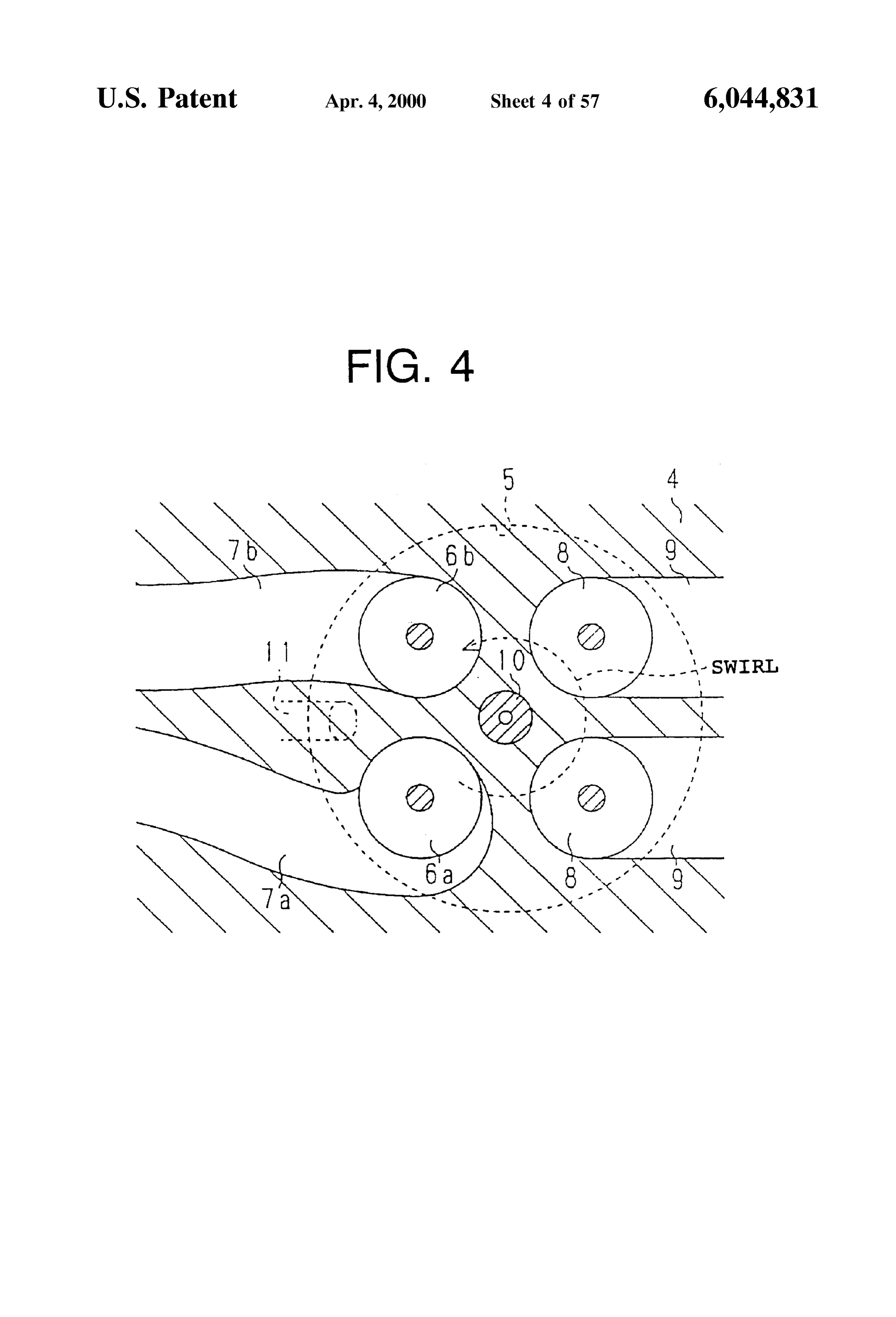
bustion engine M1 with each other. A purge control valve 45 Also, in this embodiment, as shown in FIG. 4, four valves M6 for controlling the fuel vapor amount of the evaporated are arranged per one cylinder 1a. More specifically, there are fuel to be introduced into the intake system M4 is provided provided a first intake Valve 6a, a Second intake valve 6b, a in the midway of the purge passage M5 as a purge control first intake port 7a, a Second intake port 7b, a pair of exhaust ling means for controlling, in response to the operational valves 8 and 8, and a pair of exhaust ports 9 and 9, condition of the internal combustion engine, the fuel vapor 50 respectively.
amount to be introduced from the purge passage M5 to the intake System. Also, the operational condition detecting As shown in FIG. 4, the first intake port 7a is a helical means M7 for detecting the operational condition of the intake port and the Second intake port 7b is a Straight port internal combustion engine is provided as a purge control extending Substantially Straightly. A Spark plug 10 is pro ling means. Furthermore, a purge control valve controlling 55 Vided in a central portion of an inner wall of the cylinder means M8 for controlling the purge control valve in head 4. A light Voltage is applied to the Spark plug 10 from response to the operational condition detected by the opera the ignitor 12 through a distributor (not shown). The spark ing timing of the Spark plug 10 is determined by the timing tional condition detecting means M7 is provided. of outputting the high Voltage from the ignitor 12. Furthermore, a compensation means M9 for compensat Furthermore, a fuel injection valve 11 is provided as a fuel ing the fuel vapor amount is connected to the purge control 60 injection means around the peripheral portion of the inner valve controlling means M8. The purge control valve con wall of the cylinder head in the vicinity of the first intake trolling means M8 compensates for and controls the purge valve 6a and the second intake valve 6b. Namely, in the control valve M6 on the basis of the compensation value of embodiment, the fuel from the fuel injection valve 11 is the fuel vapor amount compensated for by the compensation injected directly into the cylinder 1a. Thus, it is possible to means M9. 65 conduct So-called Stratified combustion (lean burn) together The following compensation means may be provided as with the effect of a Swirl control valve SCV 17 in addition an embodiment of the compensation means M9. to homogenous combustion.
Page 67
As shown in FIG. 3, the first intake port 7a and the secondNamely, the part of the exhaust gas is recirculated into the intake port 7b of each cylinder 1a are connected to a Surge Sucked mixture by the EGR system 51. At this time, the tank 16 through a first intake passage 15a and a Second opening degree of the EGR valve 53 is adjusted to adjust the intake passage 15b formed in each intake manifold 15. A recirculation amount of the exhaust gas. Swirl control valve (SCV) 17 is disposed in each second 5 A purge controlling unit 72 for feeding the fuel vapor into intake passage 15b. These SCVs 17 are connected to a the intake duct 20 is mounted on the intake duct 20. A Stepping motor 19 through a common Shaft 18. This Stepping canister 74 having an activated charcoal layer 73 is provided motor 19 is controlled on the basis of the output signal from in the purge controlling unit 72. A fuel vapor chamber 75 and an electronic controlling unit (hereinafter simply referred to an air chamber 76 are formed on both sides of the activated as “ECU”) to be described later. charcoal layer 73 within the canister 74. The fuel vapor The Surge tank 16 is connected to an air cleaner 21 chamber 75 is connected to a fuel reservoir 79 as the fuel through an intake duct 20. A throttle valve 23 which is storing means through a pair of check valves 77 and 78 opened and closed by another Stepping motor 22 is disposed juxtaposed to each other and allowing the flow in the in the intake duct 20. Namely, the throttle valve 23 according opposite directions to each other.
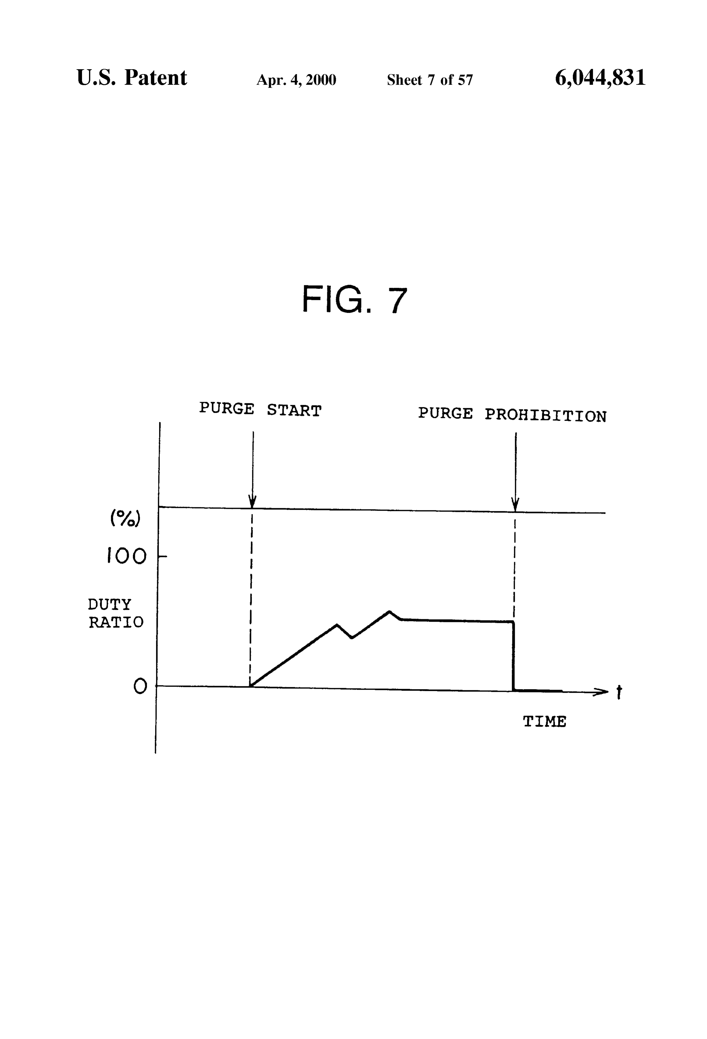
to this embodiment is of So-called electronic controlling type 15 A joint pipe 71 is connected as a purge passage between and the Stepping motor 22 is basically driven on the basis of the fuel vapor chamber 75 and the intake duct 20 down the output signal from the ECU 30 to thereby open and close stream of the throttle valve 23. A first Solenoid valve 81 and the throttle valve 23. Then, the amount of the intake air to a check valve 80 for allowing the flow only in the direction be introduced into the combustion chamber 5 through the toward the intake duct 20 from the fuel vapor chamber 75 is intake duct 20 is adjusted by the opening and closing of the provided in the joint pipe 71. The Solenoid valve 81 is a throttle valve 23.In this embodiment, the intake passage as control valve for making it possible to perform the duty an intake System is constituted by the intake duct 20, the control by the ECU 30 to be described later and is used as Surge tank 16, the first intake passage 15a and the Second a purge control valve.
intake passage 15b. Also, a throttle Sensor 25 is provided in The duty control means a control for adjusting the open the vicinity of the throttle valve 23 for detecting the opening 25 ing degree in response to a duty ratio of the input pulse degree (throttle opening degree TA). signal. The Solenoid valve 81 may be a linear valve. In this sleeve interior injection type internal combustion The air chamber 76 is in communication with the atmo engine according to the embodiment, in comparison with an sphere through a check valve 82 for allowing the flow only intake pipe injection type internal combustion engine, the on the side of the air chamber 76.
throttle valve 23 is maintained at a full throttle side except When the feed of the fuel vapor to the intake duct 20 is for an extremely low load operation. In this condition, the to be stopped, the Solenoid valve 81 is opened by the control throttle valve is controlled to be opened and closed. of the ECU 30 to be described later. At this time, the fuel Also, the throttle valve 23 is drivingly opened or closed vapor generated within the fuel reservoir 79 is caused to flow to adjust the idle Revolution speed control (ISC) of the 35 into the fuel vapor chamber 75 through the check valve 78 internal combustion engine, i.e., the intake air amount. and Subsequently to be absorbed onto the activated charcoal Incidentally, upon the homogenous combustion, the Revo within the activated charcoal layer 73.
lution Speed is controlled by the opening and closing of the When the pressure within the fuel reservoir 79 is lowered, electronic throttle vale 23, and upon the stratified the check valve 77 is opened. Accordingly, the fuel reservoir combustion, it is controlled by the fuel injection amount, and 40 79 is prevented from being deformed due to the pressure the Revolution speed is controlled by the EGR amount, the drop within the fuel reservoir 79 by the check valve 77. ignition timing and the throttle valve opening/closing. In contrast, when the fuel vapor is to be fed into the intake An exhaust manifold 14 is connected to the exhaust ports duct 20, the solenoid valve 81 is opened by the ECU 30. 9 of each cylinder. The burnt exhaust gas is purified by an Then, the air is discharged to the air chamber 76 through the exhaust gas purifying catalyst Such as a three-element 45 check valve 82, and the air is fed into the activated charcoal catalyst, NOX purifying catalyst and the like through the layer 13. At this time, the fuel absorbed on the activated exhaust manifold 14 and is discharged to an exhaust duct 13. charcoal is separated to thus cause the air (fuel vapor) Incidentally, an air/fuel ratio Sensor may be disposed containing the fuel component to flow into the fuel vapor upstream or downstream of the catalyst to control the fuel chamber 75. Subsequently, the fuel vapor is fed into the injection. 50 intake duct 20 through the check valve 80 and the Solenoid Furthermore, in the embodiment, a well know exhaust gas valve 81.
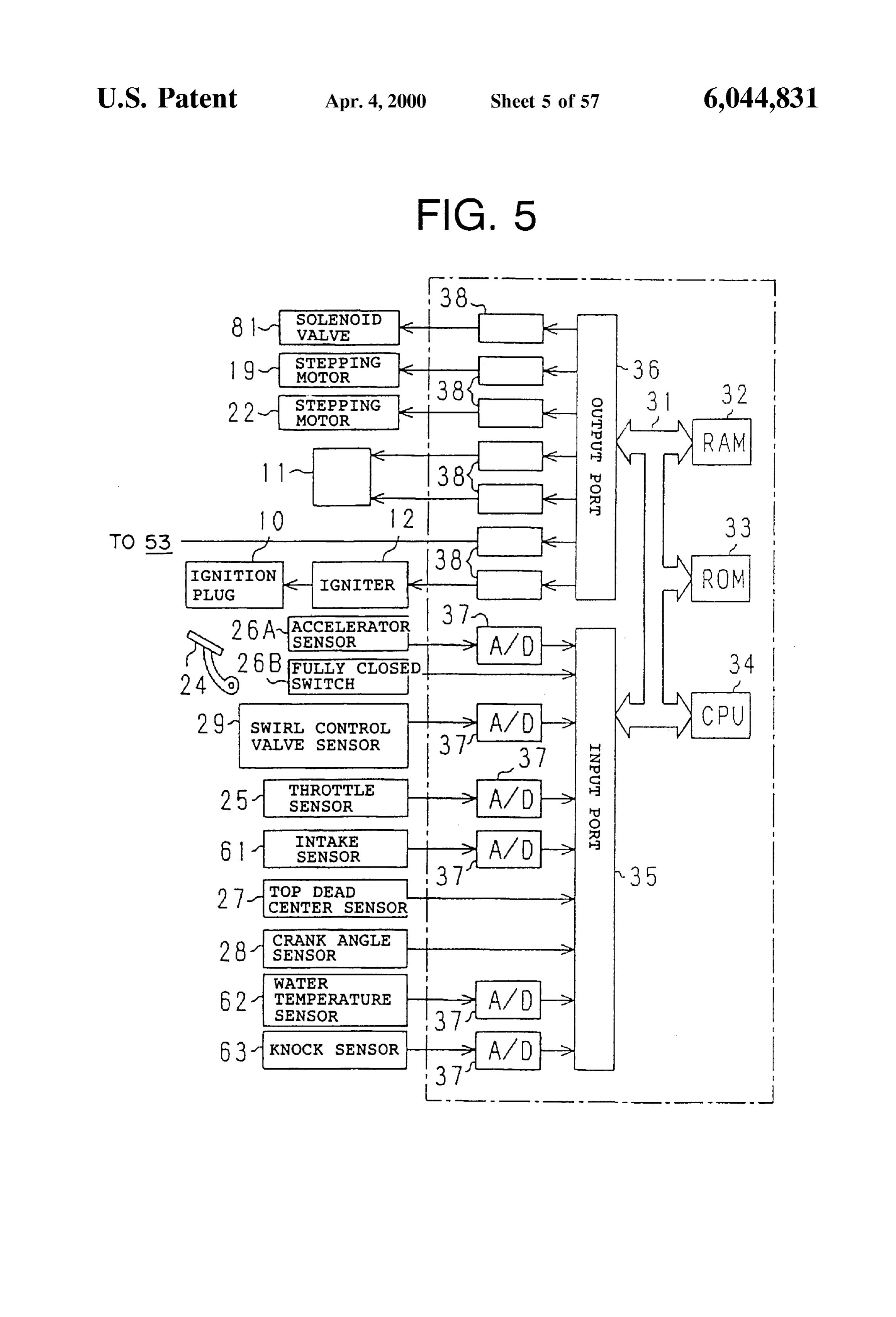
recirculation (EGR) system 51 is provided. The EGR system By the way, as shown in FIG. 5, the above-described ECU 51 includes an EGR passage 52 as an exhaust gas recircu 30 is composed of a digital computer provided with a RAM lation passage and an EGR valve 53 as an exhaust gas (random access memory) 32, a ROM (read only memory) recirculation valve disposed in the midway of the EGR 55 33, a CPU (central processing unit) 34 composed of a passage 52. The EGR passage 52 is provided for commu microprocessor, an input port 35 and an output port 36 nicating the intake duct 20 downstream of the throttle valve connected to each other through a two-way bus 31. In this 23 and the exhaust duct. embodiment, the fuel feed controlling means, the purge Also, the EGR valve 53 is internally provided a valve seat, control valve controlling means, the first compensation a valve body and a stepping motor (any of which is not 60 means, the Second compensation means, the third compen shown) which constitute the EGR mechanism. The opening sation means, the fourth compensation means, and the fifth degree of the EGR valve 53 is varied by intermittently compensation means are constituted by the ECU 30. These changing the valve body to the valve Seat by the Stepping components are made by a combination of a hardware and motor. Then, the EGR valve 53 is opened so that the part of a software. The Software is written in the ROM and is loaded the exhaust gas discharged to the exhaust duct is caused to 65 on the CPU to realize the respective means. flow to the EGR passage 52. The exhaust gas is caused to An accelerator Sensor 26A is connected to an accelerator flow to the intake duct 20 through the EGR valve 53. pedal 24 of the vehicle for generating an output Voltage in
Page 68
proportion to a Step amount of the accelerator pedal 24. An on the basis of the Signals of respective Sensors and the like accelerator degree ACCP is detected by the accelerator 25 to 29 and 61 to 63 in the ECU 30. Sensor 26. The output voltage of the accelerator Sensor 26A The respective sensors and the like 25 to 29 and 61 to 63 is inputted into the input port 35 through an AD convertor constitute the operational condition detecting means. The 37. programs for the various controls in the fuel vapor feed A fully closed switch 26B is provided to the accelerator controlling apparatus for the engine provided with the pedal 24 for detecting the condition that the Step amount of above-described Structure in accordance with the embodi the accelerator pedal 24 is zero. Namely, the fully closed ment will now be described with reference to the flowchart. Switch 26B generate a “1” signal as a fully closed signal Control in Stop of Vehicle at Idle condition XIDL in the case where the step amount of the accelerator Control by First Compensation Means pedal 24 is Zero and generates a Zero Signal in other cases. FIG. 6 is a flowchart showing a “purge control routine” in Then, the output voltage of the fully closed Switch 26B is the stop of the vehicle in the idle condition. The ECU 30 inputted into the input port 35. (CPU) executes the operation in an interrupt at every pre determined period. Incidentally, this example is the case
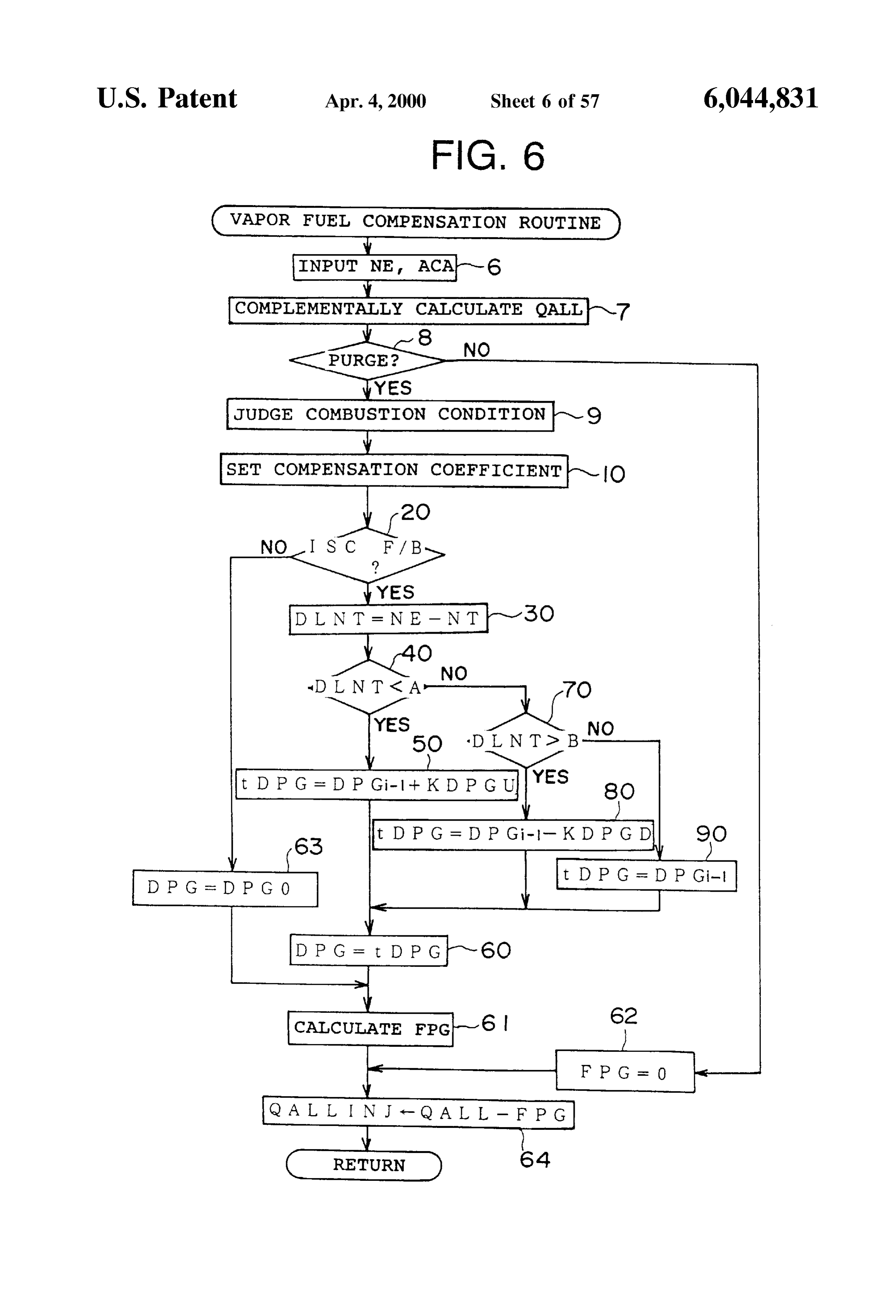
Also, for example, a top dead center Sensor 27 generates 15 where an output pulse when the piston of the first cylinder 1 a and (1-1) the characterizing points of the above-described (1) reaches the intake top dead center. This output pulse is pensated for are executed and the fuel vapor amount is com So that the engine revolution Speed is identical inputted into the input port 35. A crank angle Sensor 28 with the target revolution Speed.
generates an output pulse through every 30 CA rotation of Namely, first of all, although not shown, the basic fuel the crankshaft. This output pulse is inputted into the input injection amount corresponding to the accelerator opening port. The engine revolution Speed NE is calculated or read-in degree and the engine revolution Speed is complementally in the CPU 34 from the output pulse of the top dead center calculated from a map for determining a mutual relation Sensor 27 and the output pulse of the crank angle Sensor 28. between the engine revolution Speed and accelerator open Furthermore, the rotational angle of the above-described ing degree and the basic fuel injection amount in Step 7. A shaft 18 is detected by a Swirl control valve sensor 29 by 25 plurality of kinds of maps corresponding to the operational which the opening degree of the Swirl control valve (SCV) conditions or the combustion conditions are prepared as 17 may be detected. Then, the output of the Swirl control injection amount maps. A Suitable one is Selected from these valve sensor 29 is inputted into the input port 35 through the maps.
A/D convertor 37. In Step 8, it is judged whether or not the purge is effected. In addition, the throttle opening degree TA is detected by If the purge is effected, in Step 9, the current condition is the throttle sensor 25. The output of the throttle sensor 25 is judged from the accelerator opening degree ACA. A value of inputted into the input port 35 through the A/D convertor 37. each compensation coefficient in the purge control in cor In addition, in this embodiment, an intake pressure Sensor respondence with each combustion condition is read from 61 is provided for detecting a pressure (intake pressure PIM) the ROM 33. The various compensation coefficients are, for within the Surge tank 16. Furthermore, a water temperature 35 example, purge duty renewal amounts KDPGU and Sensor 62 is provided for detecting a temperature of cooling KDPGD.
water for the engine 1 (cooling water temperature THW). Incidentally, the engine 1 may take one of the Stratified Also, the outputs of the two sensors 61 and 62 are inputted combustion, the weak Stratified combustion, the homoge into the input port 35 through the A/D convertor 37. neous lean combustion and the homogeneous combustion Moreover, a knock sensor 63 is provided on the cylinder 40 under the control of the ECU 30. A combustion mode block 2 of the engine 1 as a knock detecting means for FMODE is set at Zero on the basis of the engine revolution detecting a knock of the engine 1. This knock Sensor 63 is Speed NE and the accelerator opening degree ACCP in the a kind of a vibration pickup having, for example, a charac case where the combustion condition is the Stratified teristic Such that a detecting ability is adjusted by the combustion, the combustion mode FMODE is set at “1” in resonance due to the identification between the frequency of 45 the case where the combustion condition is the weak Strati Vibrations generated by the knock and the intrinsic fre fied combustion, the combustion mode FMODE is set at "2" quency of Vibrations of the detecting element. Also, the in the case where the combustion condition is the homoge output of the knock Sensor 63 is inputted into the input port neous lean combustion, and the combustion mode FMODE 35 through the A/D convertor 37. Incidentally, in order to is Set at '3' in the case where the homogeneous combustion detect the torque variation, a combustion pressure Sensor for 50 is executed.
detecting the combustion pressure may be additionally used. Then, in the case where the current combustion condition Also, the ECU 30 has a gate Signal generator which is not the Stratified combustion, the judgement for this is outputs an opening/closing Signal to the input port 35 on the “NO” to thereby finish this control routine once. In the case basis of the signal from the CPU 34. Namely, the detection where the current combustion condition is the stratified Signal from the knock Sensor 63 is inputted into the input 55 combustion, the judgement for this is “YES” to shift to step port 35 in accordance with the open gate Signal from the 2O.
CPU 34. It is interrupted by the closed gate signal. Thus, a In step 20, it is judged whether or not the feed-back constant period is Set in the detection of the knock control of the idle speed control (ISC) is effected. In this (judgement). case, it is judged whether or not another ISC control routine On the other hand, connected through the associated 60 is executed. If the ISC control routine is not executed, it is driver circuits 38 to the output port 36 are the respective fuel judged that the engine revolution Speed NE is not stable, and injection valves 11, the respective Stepping motorS 19 and this judgement is "NO" to shift to step 63. If the ISC control 22, the ignitor 12, the EGR valve 53 (stepping motor) and routine is executed, it is judged that the engine revolution the Solenoid valve 81. The fuel injection valve 11, the speed NE is stable, and this judgement is “YES” to shift to stepping motors 19 and 22, the ignitor 12, the EGR valve 53, 65 step 30.
the Solenoid valve 81 and the like are Suitable controlled in In step 30, a deviation DLNT between the engine target accordance with the control program stored in the ROM 33 Revolution Speed NT and the actual engine revolution speed
Page 69
NE is calculated for the first compensation means. Incidentally, as shown in the graph of FIG. 7, if the purge Subsequently, in step 40, it is judged whether or not the execution conditions to be described later are established, deviation DLNT is smaller than the first judgement value A the control of the purge control valve in accordance with the (rpm). In step 40, in the case where the deviation is less than duty control is Such that the duty ratio is raised from Zero at the first judgement value A, i.e., when the engine is stable, 5 the time of the Start of the purge, the magnitude of the duty the process is shifted to step 50 and a temporarily demanded ratio is controlled in accordance with a predetermined purge duty value tDPG is calculated. The temporarily control, and the duty ratio becomes Zero at the moment when demanded purge duty value tdPG is one obtained by adding the purge prohibition command is effected. the purge duty renewal amount KDPGU to the previous value DPG (finally demanded duty value obtained by the Vapor If the duty ratio is determined in step 60, then the fuel previous control routine). compensation amount is calculated from the duty The purge duty renewal amount KDPGU is one obtained ratio. Namely, Since the purge amount is determined in through experiments or the like in advance and is Stored in accordance with the opening degree of the purge control the ROM 33. Subsequently, in step 60, the temporarily Valve determined by the duty ratio, the intake pipe vacuum demanded purge duty value tDPG calculated in the above 15 preSSure and the like, if the concentration of the fuel Vapor described step 50 as the finally demanded duty value DPG contained in the purge gas is known, the fuel vapor amount is set to thereby finish the control routine. is known (step 61). This fuel vapor amount is fed to the Also, in the above-described step 40, if the deviation internal combustion engine. Therefore, in Step 64, the fuel DLNT is equal to or more than the judgement value A, it is Vapor amount is Subtracted as the compensation amount judged that any variation is present in the engine revolution from the basic fuel injection amount obtained in advance in Speed, and in Step 70, it is judged whether or not the accordance with the formula:
deviation DLNT is smaller than a second judgement value B Final fuel injection amount (QALLINJ)=basic fuel injection (rpm). Incidentally, the relationship of A-B is established. In amount (QALL)-fuel vapor amount compensation amount step 70, in the case where it is judged that the deviation (FPG) (1). DLNT exceeds the Second judgement value B, the process is shifted to step 80 and the temporarily demanded purge duty 25 Accordingly, the fuel injection amount to be finally fed value tDPG is calculated. The temporarily purge duty value into the internal combustion engine may be compensated tDPG is one obtained by subtracting the purge duty renewal for.
amount KDPGD from the previous value DPG (the finally Incidentally, in the case where the operation is out of the demanded duty value obtained in the previous control purge mode in Step 8, the fuel vapor amount compensation routine). The purge duty renewal amount KDPGD is pre amount is Zero in Step 62 and the basic fuel injection amount determined by experiments or the like and is Stored in the obtained in advance is used as the final fuel injection amount
Incidentally, the values of the above-described purge duty QALLINJ without any modification. Thereafter, the fuel injection is performed in accordance renewal amounts KPGU and KDPGD may be varied accord with a separately determined fuel injection program. ing to the operational condition or the combustion condition. 35 In the “purge control routine' in FIG. 6, in step 40, if the For example, the values may be large for the homogeneous combustion, whereas the values may be Small for the Strati deviation
NT and
DLNT between the target engine revolution speed the engine revolution speed NE that is the actually fied combustion. Thus, a large amount of purge may be engine revolution Speed is less than the first judgement value introduced when the homogeneous combustion takes place, A, the actual Revolution wherein the purge variation is Suppressed in the Stratified 40 engine revolution Speed Speed NE is less than the target combustion. It is therefore possible to stabilize the combus increase the amount of the purge, the temporarilyin demanded NT. Accordingly, order to tion. Also, in Switching the combustions, if the purge duty purge duty renewal amount KDPGU is added to the previous renewal amounts KDPGU and KDPGD are changed skip value (the finally demanded duty value obtained by the wise So that the values are renewed to the renewal amounts corresponding to the combustion after Switching, it is poS 45 previous porarily control routine) DPG to thereby obtain the tem purge duty value tDPG. The Solenoid valve 81 is sible to stabilize the combustion after Switching.
Subsequently, in Step 60, the temporarily demanded purge duty value tdPG the controlled under condition that the temporarily purge is the finally demanded duty value DPG.
duty value tdPG calculated in the above-described step 80 AS a result, the amount of the purge of the fuel Vapor is as the finally demanded duty value DPG is set. increased to increase the engine revolution Speed. Also, in the above-described step 70, it is judged that the 50 Also, in the “purge control routine” in FIG. 6, in step 70, deviation DLNT is equal to or less than the judgement value if the deviation DLNT between the target engine revolution B, the process shifts to step 90 so that the temporarily speed NT and the engine revolution speed NE that is the demanded purge duty value tDPG is calculated. The tem actually engine revolution Speed exceeds the Second judge porarily demanded purge duty value tDPG is the finally ment value B, the actual Revolution speed NE is higher than demanded duty value DPG of the previous operation. 55 the target engine revolution Speed NT. Accordingly, in order Subsequently, the process shifts to step 60 and the tem to decrease the amount of the purge, the demanded duty porarily demanded purge duty value tdPG which has been value tdPG is the value obtained by Subtracting the purge obtained in step 90 is set as the finally demanded duty value duty renewal amount KDPGU from the previous value (the DPG. finally demanded duty value obtained by the previous con Incidentally, in the case where it is judged in Step 20 that 60 trol routine) DPGi-1 (step 80). Then, the temporarily the ISC control routine is not executed, that is, unless the demanded purge duty value tDPG is used as the finally ISC is stable in F/B, the duty value DPGO temporarily demanded duty value DPG. As a result, the amount of the stored in the previous stable mode is substituted for the purge of the fuel vapor is decreased to decrease the engine finally duty value DPG as the PDG (step 63). revolution Speed.
Accordingly, ECU 30 duty controls the Solenoid valve 81 65 Furthermore, in the “purge control routine” in FIG. 6, if on the basis of the finally demanded duty value DPG the deviation DLNT between the target engine revolution obtained in step 60 or 63. speed NT and the engine revolution speed NE that is the
Page 70
actually engine revolution speed is equal to higher than the compensation amount tFPG. The temporary fuel vapor first judgement value A and equal to or less than the Second amount compensation amount tPG is one obtained by judgement value B, in step 90, the temporarily demanded subtracting the fuel compensation renewal amount KFPGD purge duty value tdPG is used as the finally demanded duty from the previous value (the final fuel vapor amount com value DPG obtained by the previous routine. Then, the pensation amount obtained by the previous control routine) temporarily demanded purge duty value tDPG is the finally FPG.
demanded duty value DPG. As a result, in the case where the The fuel compensation renewal amount KFPGD is deviation falls within the above-described range, the purge obtained through experiments or the like in advance and is amount of the fuel vapor is deemed to be kept constant. stored in the ROM 33. Subsequently, in step 160, the Incidentally, the purge execution conditions in the sleeve temporary fuel vapor amount compensation amount tFPG interior direct injection type internal combustion engine are: calculated in the above-described step 150 is set as the final the warming-up completion, i.e., the State where the cooling fuel vapor amount compensation amount FPG to finish the water temperature has been raised exceeding a predeter control routine.
mined temperature, and a State where a predetermined time, Also, if, in step 140, the deviation DLNT is equal to or i.e., 30 Sec has lapsed after the cranking completion. 15 greater than the third judgement value C, in step 170, it is FIG. 8 is a flowchart showing a “routine for calculating a judged whether or not the deviation DLNT is greater than compensation amount of a fuel injection amount” at a the fourth judgement value D (rpm). Incidentally, the rela Standstill of the vehicle in an idle condition in accordance tionship of C-D is established. In the same step 170, it is with the embodiment. The ECU 30 executes interrupts at judged that the deviation DLNT exceeds the fourth judge every predetermined time interval. In this example, the fuel ment value D, the process shifts to 180 to calculate the feed amount adjustment shown in the item (1-2) is per temporary fuel vapor compensation amount tPG. The tem formed in addition to the feature of (1-1). This is attained by porary fuel Vapor amount compensation amount tFPG is the fuel feed amount controlling means. obtained by adding the fuel compensation renewal amount In this case, the fuel vapor amount compensation amount KFPGU to the previous value (the final fuel vapor amount FPG is used as a control parameter instead of the duty ratio. 25 compensation amount obtained by the previous control The final fuel injection amount QALLINJ finally fed is routine) FPG. The fuel compensation renewal amount given in the same manner as in item (1) as follows: KFPGU is obtained through experiments or the like in advance and is stored in the ROM 33.
final fuel injection amount=basic fuel injection amount-fuel vapor
Subsequential, in step 160, the temporary fuel vapor amount compensation amount amount compensation amount tFPG calculated in the above
Accordingly, if the fuel vapor amount compensation described step 180 is set as the final fuel vapor amount amount FPG is increased, the final fuel injection amount compensation amount FPG to finish the control routine. QALLINJ is decreased to obtain a lean mixture, whereas if Also, if, in the above-described step 170, the deviation the fuel vapor amount compensation amount FPG is DLNT is less than the fourth judgement value D, the engine decreased, the final fuel injection amount QALLINJ is 35 revolution Speed is deemed to be Stable in a certain range, increased to obtain a rich mixture. the process shifts to step 190 to calculate the temporary fuel When the process shifts to this routine, first of all, the Vapor amount compensation amount tFPG. The temporary ECU 30 judges in step 110 whether or not the current fuel Vapor amount compensation amount tFPG is the pre combustion condition is the stratified combustion. In this vious value FPG. Subsequently, the proceSS shifts to Step case, judgement as to whether or not the Stratified combus 40 160, the final fuel vapor amount compensation amount tion is effected is judged on the basis of the current engine FPG obtained in the above-described step 190 is set as the revolution Speed NE and the current accelerator opening final fuel vapor amount compensation amount FPG to finish degree ACCP. Then, in the case where the combustion the control routine.
condition is not the Stratified combustion, the judgement is The above-described routine corresponds to the steps 10 “NO” to thereby once complete the control routine. In the 45 to 61 and 63 of FIG. 6. The ECU 30 calculates the final fuel case where the current combustion condition is the Stratified injection amount QALLINJ in accordance with the above combustion, the judgement is “YES” and the process shifts described formula (1) with the same means as that of step 64 to step 120. of FIG. 6.
In step 120, it is judged whether or not the feed-back The ECU 30 executes the injection control of the fuel control of the idle speed control (ISC) is effected. In this 50 injection valve 11 in accordance with the final injection case, it is judged whether or not another ISC control routine amount in which the compensation amount is reflected on is effected. If the ISC control routine is not executed, the the basic fuel injection amount. engine revolution Speed NE is deemed to be unstable, and In the "fuel injection amount compensation value calcu the judgement is “NO”. Furthermore, the FPG temporarily lating routine” of FIG. 8, if the deviation DLNT is less than stored in the previous stable condition is RPGO in step 121 55 the third judgement value C, in step 150, one obtained by and is substituted for the current FPG value to thereby once subtracting the fuel compensation renewal amount KFPGD stop the control routine. If the ISC control routine is effected, from the previous value of the final fuel vapor amount the engine revolution Speed NE is deemed to be Stable, and compensation amount FPG is the temporary fuel vapor the judgement is “YES”. The process shifts to step 130. amount compensating amount tFPG. This value is used as In step 130, the deviation DLNT between the target 60 the final fuel vapor amount compensation amount FPG. engine revolution speed NT and the actual engine revolution The obtained final fuel vapor amount compensation Speed NE is calculated as the first compensation means. amount FPG is smaller than the previous FPG. Because the Subsequently, in step 140, it is judged whether or not the DLNT is less than C and the engine revolution speed is low, deviation DLNT is less than the third judgement value C the value of the FPG is decreased to make rich the final fuel (rpm). If it is judged in step 140 that the deviation DLNT is 65 injection amount QALLINJ obtained in accordance with the less than the third judgement value C, the proceSS Shifts to above-described formula (1) to increase the engine revolu step 150 to calculate the temporary fuel vapor amount tion Speed.
Page 71
Also, in the "fuel injection amount compensation value is not in the lean drive. Thus, the control routine is once calculating routine' of FIG. 8, in step 170, if the deviation Stopped. In the case where, in Step 210, the combustion DLNT exceeds the fourth judgement value D, in step 180, mode FMODE is “0”, “1” or “2”, it is judged that the one obtained by adding the fuel compensation renewal combustion mode is in the lean drive. The judgement is amount KFPGD to the previous value of the final fuel vapor “YES” and the process shifts to step 220. In step 220, in amount compensation amount FPG is used as the tempo accordance with the fully closed signal XIDL, it is judged rary fuel vapor amount compensating amount tFPG. Then, whether or not the idle is off. In the case where the fully this temporary fuel vapor amount compensation amount closed signal XIDL is “1”, the idle is not off, and the DPG tFPG is used as the final fuel vapor amount compensation temporarily stored in the previous stable mode is DPGO in amount FPG. step 221. This is substituted for the current DPG value to This final fuel vapor amount compensation amount FPG once is stop the control routine. If the fully closed signal XIDL “0”, the judgement is “YES” so that the process shifts to is replaced into the formula (1) when the final fuel injection step 230.
amount OALLINJ is calculated in the other routine. As a In step 230, it is judged whether or not the calculation result, corresponding to the increment of the FPG, the final conditions of the torque variation value DLNISMX are fuel injection amount QALLINJ is leaned to decrease the 15 established. In this case, if the torque variation value engine revolution Speed. DLNISMX is calculated in another routine, it is deemed that Also, in the "fuel injection amount compensation value the calculation conditions are established. If the torque calculating routine” of FIG. 8, if the deviation DLNT is variation value DLNISMX is not calculated in that routine, equal to or more than the third judgement value C and equal it is deemed that the calculation conditions are not estab to or less than the fourth judgement value D, in step 190, the lished. Namely, the torque variation value DLNISMX is previous final fuel vapor amount compensation amount calculated at every predetermined interval of the engine FPGi- is used as the temporary fuel vapor amount com revolution Speed. The control routine is processed immedi pensating amount tFPG. Then, this temporary fuel Vapor ately after the calculation in the cyclic period. Accordingly, amount compensation amount tFPG is used as the final fuel normally, the judgement is “YES” in step 230. Incidentally, Vapor amount compensation amount FPG. As a result, in the 25 in the case where the torque variation value DLNISMX is case where the deviation DLNT falls within the above not calculated as in the case where the Revolution Speed described range, the fuel vapor amount compensation variation is remarkable, it is deemed that the calculation amount is kept constant. conditions are not established. The process shifts to step 300. In the examples of FIGS. 6 and 8, as described above, the Incidentally, the torque is represented by a difference in purge amount of the fuel vapor is increased or decreased in angular Speed between predetermined crank angles. response to the deviation DLNT between the target Revo Accordingly, in the embodiment, the difference in torque lution speed NT and the actual Revolution speed NE and the between Zero and 720°CA (in terms of crank angles) in the fuel injection amount is increased or decreased in response Same cylinder is calculated as the torque Variation. Also, in to the deviation DLNT to be converged to the idle target this embodiment, Since the engine has four cylinders, the Revolution speed NT. 35 average value of the torque variations of these cylinderS is Namely, the finally demanded duty value DPG is obtained the torque variation value DLNISMX. The torque variation in response to the deviation DLNT between the target may be detected directly by the torque Sensor but it may be Revolution speed NT and the actual Revolution speed NE, Substituted by the engine revolution Speed or the combustion the Solenoid valve 81 is controlled in accordance with this preSSure.
value, the final fuel vapor amount compensation amount 40 If, in Step 230, it is judged that the calculation conditions FPG is calculated and the fuel injection amount is increased are established, in Step 240, the torque variation value or decreased on the basis of this value. DLNISMX is read in. In the next step 250, it is judged As a result, in the idle condition in which the stratified whether or not the torque variation value DLNISMX is combustion is effected, it is possible to effectively reduce the equal to or greater than the target torque variation value base fuel. Furthermore, irrespective of the rich or lean 45 LVLDLN as the fifth judgement value. If the torque varia mixture of the fuel vapor, it is possible to maintain a Stability tion value DLNISMX is equal to or greater than the target of the idle Revolution speed, which also contributes to the torque variation value LVLDLN, in step 260, the purge duty fuel consumption rate. renewal amount E is added to the previous value of the Running Control in Idle-Off Mode finally demanded duty value DPG as the temporarily Control by Third Compensation Means 50 demanded purge duty value tDPG. The purge duty renewal FIG. 9 is a flowchart showing a “purge control routine” amount E is obtained by experiments or the like in advance during the travel or drive of the vehicle in the idle-off mode and is stored in the ROM 33.
in the embodiment of the invention, and the ECU 30 Subsequently, in Step 270, the temporary purge duty value executes the interrupts at a predetermined time interval. The tDPG calculated in the above-described step 260 is set as the control in this case is an example of the feature (3) for 55 finally demanded duty value DPG to finish the control unit. compensating for the fuel vapor amount in response to the Also, if, in step 280, the torque variation value DLNISMX torque variation (output variation). is less than the target torque variation value LVLDLN, in When the process shifts to this routine, first of all, ECU step 280, it is judged whether or not the torque variation 30 judges in step 210 whether or not the current combustion value DLNISMX is smaller than one obtained by Subtracting condition is in a leSS level of the homogenous combustion 60 a predetermined value C. from the target torque variation condition, i.e., the Stratified combustion condition, the weak value LVLDLN. If the torque variation value DLNISMX is Stratified combustion or the homogeneous lean combustion Smaller than one obtained by Subtracting the predetermined condition or whether or not it is in a level of the homoge value C. from the target torque variation value LVLDLN, in neous combustion condition. Namely, it is judged whether step 290, the purge duty renewal amount F is subtracted the combustion mode FMODE is “0”, “1”, “2” or “3”. In this 65 from the previous finally demanded duty value DPG. The case, in the case where the combustion mode FMODE is out purge duty renewal amount F is obtained by experiments or of “0”, “1” and “2”, it is judged that the combustion mode the like in advance and is stored in the ROM 33.
Page 72
Subsequently, in Step 270, the temporary purge duty value condition or whether or not it is in a level of the homoge tDPG calculated in the above-described step 290 is set as the neous combustion condition. Namely, it is judged whether final demanded duty value DPG to finish the control routine. the combustion mode FMODE is “0”, “1”, “2” or “3”. In this Also, in Step 280, in the case where the torque variation case, in the case where the combustion mode FMODE is out value DLNISMX is equal to or more than a value obtained of “0”, “1” and “2”, it is judged that the combustion mode by Subtracting the predetermined value C. from the target is not in the lean drive. Thus, the control routine is once torque variation value LVLDLN, the process shifts to step stopped. In the case where, in step 310, the combustion mode FMODE is “0”, “1” or “2”, it is judged that the 300. In the case where the process shifts from step 230 or combustion step 280 to step 300, the temporarily demanded purge duty “YES” and the mode is in the lean drive. The judgement is value tdPG is the previous value of the finally demanded process shifts to step 320. duty value DPGi-i. Subsequently, the process shifts to step XIDL, In step 320, in accordance with the fully closed signal 270, and the temporary demanded purge duty value tdPG where the it is judged whether or not the idle is off. In the case obtained in the step 300 is set as the finally demanded duty and the DPG fully closed signal XIDL is “1”, the idle is not off, temporarily stored in the previous stable mode value DPG to stop the control routine. is DPGO in step 321. This is substituted for the current DPG Accordingly, ECU 30 duty controls the Solenoid valve 81 15 value to once stop the control routine. If the fully closed on the basis of the finally demanded duty value DPG. signal XIDL is “0”, the judgement is “YES” so that the The above-described routine corresponds to the steps 10 process shifts to step 330.
to 60 and 63 of FIG. 6. The ECU 30 converts the DPG to the In step 330, it is judged whether or not the calculation FPG in step 61 and calculates the final fuel injection amount conditions of the torque variation value DLNISMX are OALLINJ in accordance with the above-described formula established. The judgement of step 330 is performed in the (1) in the same manner as in step 64 of FIG. 6. same manner as in step 230 of the control routine of FIG. 9. In the “purge control routine' of FIG. 9, if the torque If, in step 330, it is judged that the calculation conditions variation value DLNISMX is equal to or more than the target are established, in step 340, the torque variation value torque variation value LVLDLN, in order to increase the DLNISMX is read in. In the next step 350, it is judged purge amount, the temporarily demanded purge duty value 25 whether or not the torque variation value DLNISMX is less tDPG is obtained by adding the purge duty renewal amount than the target torque variation value LVLDLN as the sixth E to the previous value (the finally demanded duty value judgement value. If the torque variation value DLNISMX is obtained in the previous control routine) DPG. As a result, less than the target torque variation value LVLDLN, in step the purge amount of the fuel vapor is increased to increase 360, the fuel compensation renewal amount G is added to the engine revolution speed. the previous value of the final fuel vapor amount compen Also, in the “purge control routine' of FIG.9, if the torque sation amount FPGi-l as the temporary fuel vapor amount variation value DLNISMX is less than the value obtained by compensation amount tFPG. The fuel compensation renewal Subtracting the predetermined value C, from the target torque amount G is obtained by experiments or the like in advance variation value LVLDLN, in order to decrease the purge and is stored in the ROM 33.
amount, the temporarily demanded purge duty value tdPG 35 Subsequently, in step 370, the temporary fuel vapor is obtained by Subtracting the purge duty renewal amount F amount compensation amount tFPG calculated in the above from the previous value (the finally demanded duty value described step 360 is set as the final fuel vapor amount obtained in the previous control routine) DPG. As a result, compensation amount FPG to finish the control routine. the purge amount of the fuel vapor is decreased to decrease Also, if, in step 350, the torque variation value DLNISMX the engine revolution speed. 40 is less than the target torque variation value LVLDLN, in Furthermore, in the “purge control routine' of FIG. 9, if step 380, it is judged whether or not the torque variation the torque variation value DLNISMX is less than the target value DLNISMX is equal to or greater than one obtained by torque variation value LVLDLN and if the torque variation adding a predetermined value B to the target torque variation value DLNISMX is equal to or more than the value obtained value LVLDLN. If the torque variation value DLNISMX is by Subtracting the predetermined value C. from the target 45 equal to or greater than one obtained by adding the prede torque variation value LVLDLN, in step 300, the tempo termined value B to the target torque variation value rarily demanded purge duty value tdPG is the finally LVLDLN, in step 390, the fuel compensation renewal demanded duty value DPG. Then, the temporarily demanded amount H is subtracted from the previous value of the final purge duty value tdPG is used as the finally demanded duty fuel vapor amount compensation amount FPG. The fuel value DPG. As a result, in the case where the torque 50 compensation renewal amount H is obtained by experiments variation value DLNISMX falls within the above-described or the like in advance and is stored in the ROM 33. range, the purge amount of the fuel vapor is deemed to be Subsequently, in step 370, the temporary fuel vapor kept constant. amount compensation amount tFPG calculated in the above Next, FIG. 10 is a flowchart showing a “fuel injection described step 390 is set as the final fuel vapor amount amount compensation value calculating routine' during the 55 compensation amount FPG to finish the control unit. travel or drive of the vehicle in the idle-off mode in the Also, in Step 280, in the case where the torque variation embodiment of the invention, and the ECU 30 executes the value DLNISMX is less than a value obtained by adding the interrupts at a predetermined time interval. The control in predetermined value B to the target torque variation value this case is an example of the feature (3) for adjusting the LVLDLN, the process shifts to step 400. In the case where fuel feed amount in response to the output variation in the 60 the process shifts from step 330 or step 380 to step 400, the internal combustion engine with the third compensation temporary vapor amount compensation amount tFPG is the CS. previous value of the final fuel vapor amount compensation When the process shifts to this routine, first of all, ECU amount FPG. Subsequently, the process shifts to step 370, 30 judges in step 310 whether or not the current combustion and the temporary fuel vapor amount compensation amount condition is in a leSS level of the homogenous combustion 65 tFPG obtained in the step 400 is set as the final fuel vapor condition, i.e., the Stratified combustion condition, the weak amount compensation amount FPG to Stop the control Stratified combustion or the homogeneous lean combustion routine.
Page 73
The above-described routine corresponds to the steps 10 is enhanced, and the fuel amount is further increased, the to 61 and 63 of FIG. 6. The ECU 30 calculates the final fuel torque variation is worse. Accordingly, in the form of this injection amount QALLINJ in accordance with the above embodiment, if the target torque variation value LVDLN is described formula (1) in the same manner as in step 64 of set at the optimum condition of the torque variation of FIG. FIG. 6. 5 11, the curve a to b may be obtained. As a result, the fuel Then, the ECU 30 executes the injection control of the compensation is carried out and the control is effected So that fuel injection valve 11 in accordance with the final injection the torque variation at c due to the fuel exceSS may be amount QALLINJ in which the compensation amount is avoided. It is thus possible to converge the torque variation reflected on the basic fuel injection amount. in a predetermined range about a center of the target torque In the “the fuel injection amount compensation calculat variation LVLDLN.
ing routine” of FIG. 10, in step 380, if the torque variation <Example where the fuel vapor amount is compensated value DLNISMX is equal to or more than the value obtained for the Second compensation means in response to the by adding the predetermined value B to the target torque engine revolution Speed of the internal combustion engine variation value LVLDLN, in step 390, the value obtained by irrespective of the operational condition> Subtracting the fuel compensation renewal amount H from 15 FIG. 12 shows a “purge control routine' for controlling the previous value of the final fuel vapor amount compen the purge with the Second compensation means only with sation amount FPG is the temporary fuel vapor amount reference to the engine revolution Speed while using the compensation amount tPG. Then, the temporary fuel vapor feature of (2). Also, this routine is executed at every prede amount compensation amount tFPG is used as the final fuel termined time interval by-the EUC 30.
Vapor amount compensation amount FPG, and it is Sub When the process shifts to this routine, first of all, in step tracted as the parameter for the idle Revolution Speed 410, the deviation DLNE between the engine revolution control from the basic fuel injection amount when the speed a NEO in the execution of the previous routine and the calculation of the final fuel injection amount QALLINJ is current engine revolution Speed NE. Subsequently, in Step executed to another routine. 420, it is judged whether or not the deviation DLNE is The FPG is smaller than the previous one, and hence the 25 greater than Zero. In Step 420, when it is judged that the final fuel injection amount QALLINJ is large so that the deviation DLNE is greater than Zero, the engine revolution air/fuel ratio is enriched to Suppress the torque variation. speed is liable to be increased. The process shifts to step 430. Also, in the step 350 of the “the fuel injection amount The temporarily demanded purge duty value tDPG is compensation calculating routine” of FIG. 10, if the torque obtained by adding the purge duty renewal amount KDPGU variation value DLNISMX is less than the target torque to the previous value (the finally demanded value obtained variation value LVLDLN, in step 360, the value obtained by by the previous control routine) DPG. This purge duty adding the fuel compensation renewal amount G to the renewal amount KDPGU is obtained by experiments or the previous value of the final fuel vapor amount compensation like in advance and is stored in the ROM 33. Next, in Step amount FPG is the temporary fuel vapor amount compen 440, the temporarily purge duty value tDPG calculated by sation amount tRPG. Then, the temporary fuel vapor amount 35 the above-described step 430 is set as the finally demanded compensation amount tPG is used as the final fuel vapor duty value DPG to stop the control routine. amount compensation amount FPG, and it is Subtracted as Also, unless the deviation DLNE is greater than Zero in the parameter for the idle Revolution speed control when the the above-described step 420, the process shifts to step 450 calculation of the final fuel injection amount QALLINJ is and it is judged whether or not the deviation DLNE is executed in accordance with the formula (1). In this case, the 40 smaller than Zero. If, in step 450, the deviation DLNE is FPG is larger than the previous one. As a result, the smaller than Zero, the process shifts to step 460. The combustion is leans. In this case, the Since the vapor temporarily demanded purge duty value tdPG is obtained by concentration is high, the purge amount is decreased but the subtracting the purge duty renewal amount KDPGD from torque variation is not increased. the previous value (the finally demanded value obtained by Furthermore, in the “the fuel injection amount compen 45 the previous control routine) DPG. This purge duty sation calculating routine” of FIG. 10, if the torque variation renewal amount KDPGD is obtained by experiments in value DLNISMX is equal to or more than the target torque advance and is stored in the ROM 33.
variation value LVLDLN and less than the value obtained by Subsequently, in step 440, the temporarily demanded Subtracting the predetermined value D from the target torque purge duty value tdPG calculated in the above-described variation value LVLDLN, in step 400, the temporary fuel 50 step 460 is set as the finally demanded duty value DPG to Vapor amount compensation amount tFPG is the previous Stop the control routine.
value of the final fuel vapor amount compensation amount In step 450, in the case where it is not judged that the FPG. As a result, in the case where the torque variation value deviation DLNE is Smaller than Zero, the deviation DLNE is DLNISMX falls within the above-described range, the fuel Zero. It is judged that no variation occurs in the engine Vapor injection amount compensation amount FPG is 55 revolution speed. In this case, the process shifts to step 480, deemed to be kept constant. and the temporarily demanded purge duty value tdPG takes AS described above, in the forms of FIGS. 9 and 10, since the same value as the previous value (the final duty value the feed-back control is applied to the target torque variation obtained by the previous control routine) DPG. LVLDLN, even if the misfire or surge caused by the purge In Step 440, the temporarily demanded purge duty value is generated, it is possible to effectively reduce the amount 60 tDPG calculated in the above-described step 480 is set as the of fuel, and in addition, Since the control is effected So that finally demanded duty value DPG to complete the control the torque variation is converged to the target torque varia routine.
tion value, the drivability is well kept to enhance the fuel Accordingly, ECU 30 duty controls the Solenoid valve 81 consumption rate. on the basis of the finally demanded duty value DPG. Incidentally, FIG. 11 is a graph showing the characteris 65 The above-described routine corresponds to the steps 10 tics of the torque variation and the fuel amount. In FIG. 11, to 61 and 63 of FIG. 6. The ECU 30 converts the DPG to the if the fuel amount is slightly increased, the torque variation FPG in step 61 and calculates the final fuel injection amount
Page 74
OALLINJ in accordance with the above-described formula as the compensation coefficient tRDPGCH. The coefficient (1) in the same manner as in step 64 of FIG. 6. K2 (K2<K1) is a non-dimensional value and determined in In the sleeve interior injection type internal combustion advance through experiments or the like So that when the engine which is operated under the condition of the Sub combustion is changed from the previous combustion mode Stantially fully opened throttle valve in many cases, Since the FMODE (homogeneous lean combustion) to the current intake air amount, i.e., the vacuum pressure is kept constant, combustion mode FMODE (stratified combustion), the if the purge amount is to be controlled in response to at least purge amount of the fuel vapor and the fuel injection amount one value of the intake pipe vacuum pressure, the load (air are at optimum, i.e., at values at which the combustion is not amount/engine revolution speed) the air intake amount, in worse upon the mode Switching operation. The coefficient the case where the same purge amount is executed for the K2 is stored in the ROM 33. After that, the process shifts to low Revolution speed stratified combustion and the high step 660 of FIG. 18.
Revolution Speed homogeneous combustion, the combus In the case where, in the above-described step 623, it is tion would be unstable on the low Revolution speed side or judged that the current combustion mode FMODE is “3” the misfire would occur. In this example, without depending (homogeneous combustion). K3 (<1.0) is set as the com the intake Vacuum pressure, only the engine revolution 15 pensation coefficient tkDPGCH. The coefficient K3 Speed is utilized as the control parameter, and the purge (K2<K1<K3) is a non-dimensional value and determined in amount is controlled in response to the engine revolution advance through experiments or the like So that when the speed. It is therefore possible to obtain the stable combus combustion is changed from the previous combustion mode tion. FMODE (homogeneous lean combustion) to the current <Control upon a combustion mode Switching operation by combustion mode FMODE (homogenous combustion), the the fourth compensation means> purge amount of the fuel vapor and the fuel injection amount Next, FIGS. 13 to 18 are flowcharts showing a “DPG and are at optimum, i.e., at values at which the combustion is not FPG compensation calculating routine' upon a combustion worse upon the mode Switching operation. The coefficient mode Switching operation in the form of the embodiment, K3 is stored in the ROM 33. After that, the process shifts to and the ECU 30 executes interrupts at every predetermined 25 step 660 of FIG. 18.
interval. <Control upon a mode Switching operation from the <Control upon a mode Switching operation from the previous weak Stratified combustion> previous homogeneous lean combustion> In step 620 shown in FIG. 13, in the case where the When the process shifts to this routine, in step 610 shown previous combustion FMODE is not “2” (homogeneous lean in FIG. 13, the current operational mode (combustion mode) combustion), the process shifts to step 630 and it is judged and the operational mode (combustion mode) upon the whether or not the previous combustion mode FMODE is previous control are read in, and in Step 620, it is judged “1” (weak stratified combustion). In the case where the whether or not the previous combustion mode FMODE is previous combustion FMODE is “1”, the process shifts to “2” (homogenous lean combustion). In this step 620, in the Step 631 and it is judged whether or not the current com case where the combustion mode FMODE is “2', the 35 bustion mode FMODE is “2” (homogeneous lean process shifts to step 621 shown in FIG. 14. combustion).
In the case where, in Step 621, the current combustion In the case where the previous combustion FMODE is “2” mode FMODE is “1” (weak stratified combustion), the (homogeneous lean combustion), the process shifts to Step proceSS shifts to Step 624, and K1 is Set to a compensation 634.
coefficient tRDPGCH. This coefficient K1 (<1.0) is a non 40 In step 634, K4 is set to the compensation coefficient dimensional number. The coefficient K1 is determined in tKDPGCH. This coefficient K4 (<1.0) is a non-dimensional advance through experiments or the like So that when the number. The coefficient K4 is determined in advance combustion is changed from the previous combustion mode through experiments or the like So that when the combustion FMODE (homogeneous lean combustion) to the current is changed from the previous combustion mode FMODE combustion mode FMODE (weak stratified combustion), the 45 (weak Stratified combustion) to the current combustion purge amount of the fuel vapor and the fuel injection amount mode FMODE (homogeneous lean combustion), the purge are at optimum, i.e., at values at which the combustion is not amount of the fuel vapor and the fuel injection amount are worse upon the mode Switching operation. The coefficient at optimum, i.e., at values at which the combustion is not K1 is stored in the ROM 33. After that, the process shifts to worse upon the mode Switching operation. The coefficient step 660 of FIG. 18. 50 K4 is stored in the ROM 33. After that, the process shifts to In the case where, in the above-described step 621, the step 660 of FIG. 18.
current combustion mode FMODE is not “1” (weak strati In the case where, in the above-described step 631, the fied combustion), the process shifts to step 622. In step 622, current combustion mode FMODE is not “2” (homogenous it is judged whether or not the current combustion mode lean combustion), the process shifts to step 632. In step 632, FMODE is “0” (stratified combustion). In the same step 622, 55 it is judged whether or not the current combustion mode the current combustion mode FMODE is not “0” (stratified FMODE is “0” (stratified combustion). In the same step 632, combustion), the process shifts to step 623. In step 623, it is the current combustion mode FMODE is not “0” (stratified judged whether or not the current combustion mode combustion), the process shifts to step 633. In step 633, it is FMODE is “3” (homogeneous combustion). If the current judged whether or not the current combustion mode mode is not “3”, it is judged that the combustion mode 60 FMODE is “3” (homogeneous combustion). If the current FMODE is not changed. The process shifts to 627. 1.0 is set mode is not “3”, it is judged that the combustion mode as the compensation coefficient tRDPGCH. The coefficient FMODE is not changed. The process shifts to 637. 1.0 is set of 1.0 is stored in advance. After that, the process shifts to as the compensation coefficient tRDPGCH. The coefficient step 660 of FIG. 18. of 1.0 is stored in the ROM 33 in advance. After that, the Also, in the case where, in the above-described Step 622, 65 process shifts to step 660 of FIG. 18. the current combustion mode FMODE is “0” (stratified Also, in the case where, in the above-described Step 632, combustion), the process shifts to step 625. K2 (1.0) is set the current combustion mode FMODE is “0” (stratified
Page 75
combustion), the process shifts to step 635. K5 (<1.0) is set is set as the compensation coefficient tkDPGCH. The coef as the compensation coefficient tRDPGCH. The coefficient ficient K8 (K7<K8) is a non-dimensional value and deter K5 (<1.0, K4>K5) is a non-dimensional value and deter mined in advance through experiments or the like So that mined in advance through experiments or the like So that when the combustion is changed from the previous com when the combustion is changed from the previous com bustion mode FMODE (stratified combustion) to the current bustion mode FMODE (homogeneous lean combustion) to combustion mode FMODE (homogenous lean combustion), the current combustion mode FMODE (stratified the purge amount of the fuel vapor and the fuel injection combustion), the purge amount of the fuel vapor and the fuel amount are at optimum, i.e., at values at which the com injection amount are at optimum, i.e., at values at which the bustion is not worse upon the mode Switching operation. The combustion is not worse upon the mode Switching operation. coefficient K8 is stored in the ROM 33. After that, the The coefficient K5 is stored in the ROM 33. After that, the process shifts to step 660 of FIG. 18. process shifts to step 660 of FIG. 18. In the case where, in the above-described step 643, it is In the case where, in the above-described step 633, it is judged that the current combustion mode FMODE is “3” judged that the current combustion mode FMODE is “3” (homogeneous combustion). K9 (<1.0) is set as the com (homogeneous combustion), K6 (<1.0) is set as the com 15 pensation coefficient tRDPGCH. The coefficient K9 pensation coefficient tRDPGCH. The coefficient K6 (<1.0, (K7<K8<K9) is a non-dimensional value and determined in K5<K4<K6) is a non-dimensional value and determined in advance through experiments or the like So that when the advance through experiments or the like So that when the combustion is changed from the previous combustion mode combustion is changed from the previous combustion mode FMODE (stratified combustion) to the current combustion FMODE (homogeneous lean combustion) to the current mode FMODE (homogeneous combustion), the purge combustion mode FMODE (homogenous combustion), the amount of the fuel vapor and the fuel injection amount are purge amount of the fuel vapor and the fuel injection amount at optimum, i.e., at values at which the combustion is not are at optimum, i.e., at values at which the combustion is not worse upon the mode Switching operation. The coefficient worse upon the mode Switching operation. The coefficient K9 is stored in the ROM 33. After that, the process shifts to K6 is stored in the ROM 33. After that, the process shifts to 25 step 660 of FIG. 18.
step 660 of FIG. 18. <Control upon a mode Switching operation from the <Control upon a mode Switching operation from the previous homogeneous combustion> previous Stratified combustion> In step 640 shown in FIG. 13, in the case where the In step 630 shown in FIG. 13, in the case where the previous combustion FMODE is not “3” (stratified previous combustion FMODE is not “1” (weak stratified combustion), the process shifts to step 651 of FIG. 17 and it combustion), the process shifts to step 640 and it is judged is judged whether or not the previous combustion mode whether or not the previous combustion mode FMODE is FMODE is “1” (weak stratified combustion). In the case “0” (stratified combustion). In the case where the previous where the previous combustion FMODE is “1” (weak strati combustion FMODE is “0”, the process shifts to step 641 fied combustion), the process shifts to step 654. and it is judged whether or not the current combustion mode 35 In step 654, K10 is set to the compensation coefficient FMODE is “1” (stratified combustion). tKDPGCH. This coefficient K10 (<1.0) is a non-dimensional In the case where the previous combustion FMODE is “1” number. The coefficient K10 is determined in advance (stratified combustion), the process shifts to step 644. through experiments or the like So that when the combustion In step 644, K7 is set to the compensation coefficient is changed from the previous combustion mode FMODE tKDPGCH. This coefficient K7 (<1.0) is a non-dimensional 40 (homogeneous combustion) to the current combustion mode number. The coefficient K7 is determined in advance FMODE (weak stratified combustion), the purge amount of through experiments or the like So that when the combustion the fuel vapor and the fuel injection amount are at optimum, is changed from the previous combustion mode FMODE i.e., at values at which the combustion is not worse upon the (stratified combustion) to the current combustion mode mode switching operation. The coefficient K10 is stored in FMODE (weak stratified combustion), the purge amount of 45 the ROM33. After that, the process shifts to step 660 of FIG. the fuel vapor and the fuel injection amount are at optimum, 18.
i.e., at values at which the combustion is not worse upon the In the case where, in the above-described step 651, the mode Switching operation. The coefficient K7 is stored in the current combustion mode FMODE is not “1” (weak strati ROM33. After that, the process shifts to step 660 of FIG. 18. fied combustion), the process shifts to step 652. In step 652, In the case where, in the above-described step 641, the 50 it is judged whether or not the current combustion mode current combustion mode FMODE is not “1” (weak strati FMODE is “0” (stratified combustion). In the same step 652, fied combustion), the process shifts to step 642. In step 642, the current combustion mode FMODE is not “0” (stratified it is judged whether or not the current combustion mode combustion), the process shifts to step 653. In step 653, it is FMODE is “2” (weak homogeneous combustion). In the judged whether or not the current combustion mode same step 642, the current combustion mode FMODE is not 55 FMODE is “2” (homogeneous lean combustion). If the “2 (homogeneous lean combustion), the process shifts to current mode is not "2", it is judged that the combustion step 643. In step 643, it is judged whether or not the current mode FMODE is not changed. The process shifts to 657. 1.0 combustion mode FMODE is “3” (homogeneous is set as the compensation coefficient tkDPGCH. The coef combustion). If the current mode is not “3”, it is judged that ficient of 1.0 is stored in the ROM 33 in advance. After that, the combustion mode FMODE is not changed. The process 60 the process shifts to step 660 of FIG. 18. shifts to step 647. 1.0 is set as the compensation coefficient Also, in the case where, in the above-described step 652, tKDPGCH. The coefficient of 1.0 is stored in the ROM 33 the current combustion mode FMODE is “0” (stratified in advance. After that, the process shifts to step 660 of FIG. combustion), the process shifts to step 655. K11 (<1.0) is set 18. as the compensation coefficient tRDPGCH. The coefficient Also, in the case where, in the above-described Step 642, 65 K11 (K11<K10) is a non-dimensional value and determined the current combustion mode FMODE is “2” (homogeneous in advance through experiments or the like So that when the lean combustion), the process shifts to step 645. K8 (<1.0) combustion is changed from the previous combustion mode
Page 76
FMODE (homogeneous combustion) to the current combus ing to the vapor concentration detected by the concentration tion mode FMODE (stratified combustion), the purge detecting means, from the correspondence relationship of amount of the fuel vapor and the fuel injection amount are the ROM to thereby obtain the optimum compensation at optimum, i.e., at values at which the combustion is not coefficient. Incidentally, for example, an HC Sensor worse upon the mode Switching operation. The coefficient 5 (hydrocarbon Sensor) provided in the intake pipe or in the K10 is stored in the ROM 33. After that, the process shifts purge passage may be used as the concentration detecting to step 660 of FIG. 18. means but it is possible to reversely calculate the fuel In the case where, in the above-described step 653, it is concentration from the oxygen concentration by detecting judged that the current combustion mode FMODE is “2” the concentration of the oxygen contained in the purge gas (homogeneous lean combustion). K12 (<1.0) is set as the with a oxygen Sensor.
compensation coefficient tRDPGCH. The coefficient K12 In FIGS. 13 to 18, the compensation coefficients are (K11<K10<K12) is a non-dimensional value and deter delicately changed from K1 to K12 in association with the mined in advance through experiments or the like So that mode Switching operations, whereby the optimum fuel when the combustion is changed from the previous com Vapor amount feed may be effected to prevent the degrada bustion mode FMODE (homogeneous combustion) to the 15 tion of the combustion in addition to the maintenance of the current combustion mode FMODE (homogeneous lean Sufficient amount of the purge.
combustion), the purge amount of the fuel vapor and the fuel Namely, in the “DPG and FPG compensation calculation injection amount are at optimum, i.e., at values at which the routine' of the combustion mode Switching operation of combustion is not worse upon the mode Switching operation. FIGS. 13 to 18, when the combustion mode is changed, the The coefficient K12 is stored in the ROM 33. After that, the compensation coefficient is Selected in accordance with the process shifts to step 660 of FIG. 18. condition in which the combustion modes FMODE are When the process shifts from the above-described respec Switched. Since the Selected compensation coefficient is at tive steps to the step 660, in step 660, the compensation the optimum So that the combustion is not unstable upon the coefficient tkDPGCH set in each step is set as the final mode Switching operation, the Solenoid valve 81 and the fuel compensation coefficient DDPGCH. In the next step 670, 25 injection valve 11 are controlled So that both the purge the values obtained by multiplying the finally demanded amount and the fuel injection amount are at optimum values. duty value DPG-1, calculated at the previous control cycle, AS a result, upon the combustion mode Switching operation, by the final compensation coefficient KDPGCH is used as it is possible to avoid the worse combustion. Incidentally, the finally demanded duty value DPG. In the next step 680, the present invention is not limited to the above-described the value obtained by multiplying the final fuel vapor embodiment but may be applied as follows. amount compensation amount FPGI1, calculated at the (A) In the “DPG and FPG compensation calculation previous control cycle, by the final compensation coefficient routine'
KDPGCH is used as the final fuel vapor amount compen FIG. 13 ofin the the combustion mode Switching operation of form of the foregoing embodiment, the sation amount FPG to thereby complete the calculation compensation coefficients K1 and K2 are the values routine. 35 obtained by the experiments in advance but may be calcu
Accordingly, the ECU 30 performs the injection control of lated by the ratio of the fuel injection the fuel injection valve 11 as well as controls the Solenoid combustion mode to the fuel injectionamount amount in the previous in the current valve 81 on the basis of the final fuel vapor amount combustion mode.
compensation amount FPG and the finally demanded duty value DPG calculated by the “DPG and FPG compensation 40 interior (B) The present invention is embodied to the sleeve calculation routine' upon the combustion mode Switching but mayinjection be type engine 1 in the foregoing embodiment embodied to a type in which a general Stratified mode.
Thus, in accordance with the Switching operation of combustion or weak stratified combustion is performed. For example, the present invention may be applied to a type in combustion conditions, the Dapor fuel amount is compen which
Sated for, the purge control Dale is controlled and the fuel 45 intake the fuel is injected to a bottom side of each of the valves 6a and 6b of the intake ports 7a and 7b.
injection amount is controlled So that it is possible to Although the fuel maintain the optimum combustion in response to the com the intake valves injection valve is provided on the side of bustion condition. It can be said that as described in (4-4), invention to the arrangement6b init which 6a and is possible to apply the the fuel is injected the system is proDided with the fuel feed amount control ling means for adjusting the fuel feed amount in response to 50 directly to the interior of the cylinder bore (combustion the Switching mode upon the combustion condition Switch chamber 5). Furthermore, the invention may be applied to an engine that may effect the lean combustion with the SCV 17.
ing operation of the internal combustion engine.
<Control in response to the concentration of the fuel Accordingly, in this specification, the lean combustion Vapor> means to include these variations. (C) In the foregoing A relationship between the above-described respective 55 embodiment, the invention is embodied to the gasoline compensation coefficients and the vapor concentration will engine 1 as the internal combustion engine, it is possible to now be described. This is an example of the control Such as apply the invention to a diesel engine or the like. purge control valve or the like by the fifth compensation In the foregoing embodiment, when the fuel Vapor means while utilizing the feature of (5-1). amount is compensated for by the fourth compensation FIG. 19 shows the relationship between the above 60 means, a judgement means for judging the Switching timing described respective compensation coefficients (K1 to K12) of the combustion conditions of the internal combustion and the vapor concentration. In FIG. 19, the relationships, engine, the fuel vapor amount is compensated for by the C1 (lower concentration)<C2<C3 ... (high concentration), fourth compensation means on the basis of the same judge and K, K", K, K', ..., are established. ment means. In this case, the ECU 30 constitutes the The relationship shown in FIG. 19 is stored in advance in 65 judgement means, and the steps 420, 430,480,510 and 520 the form of a map in the ROM. The fifth compensation correspond to the judgement means. The combustion con means calculates the compensation coefficient, correspond dition Switching timing is judged by the judgement means.
Page 77
<Control by Control Delay Means (4-1)> In the case where, in step 683, the operation is out of the By the way, when the combustion modes are Switched, it purge, in Step 687, the fuel vapor amount compensation is possible to delay, by the control delay means, the time amount is Zero.
until the opening degree change of the purge control valve After the fuel vapor amount compensation amount FPG is or the fuel injection condition change is Started in the determined in steps 685 and 687, the process shifts to step Switching operation of the combustion conditions. More 686 to determine the final fuel injection amount QALLINJ. specifically, as shown in FIG. 20, when the combustion is In this case, the final fuel injection amount QALLINJ is changed from the combustion mode A to the combustion determined by Subtracting the fuel vapor amount compen mode B, it is preferable to change the modes, i.e., DPGs and sation amount FPG from the basic fuel injection amount FPGs after the predetermined delay period has lapsed. This is because to prevent a So-called hunching moving from the QALL calculated in advance in step 682. Thereafter the fuel injection is effected in accordance with mode A to B and B to Ain a short period of time. This control the fuel injection program determined separately. delay means is realized by the program on the CPU. Incidentally, other calculation methods of the fuel vapor Incidentally, the predetermined delay time may be varied by the flow rate of the intake air, the Revolution speed or the 15 amount compensation amount (FPG) are typically exempli like. fied as a method for obtaining it from the purge gas amount <Control by Control Delay Means (4-2) and (4-3)> Qp as shown in FIG. 25 and a method for obtaining it from When the opening degree changing rate of the purge the intake manifold pressure as shown in FIG. 26. control valve or the fuel injection condition changing rate is Incidentally, the routine shown in FIG. 23 is repeatedly gradually changed with the change rates) from the previous executed at a predetermined time interval. DPG to the current DPG in response to the combustion Since the fuel Vapor compensation amount is detected by condition upon the combustion mode Switching operation by such a routine, particularly, steps 684 and 685, a large a changing rate controlling means as shown in FIG. 21, it is amount of fuel vapor may be processed without any adverse possible to obtain the stable combustion during the shift. affect to the drivability or the emission. Furthermore, the changing rates shown in FIG. 21 are <Change of the fuel injection condition in accordance made different from the mode of the combustion Switching 25 with the compensation of the fuel Vapor amount> according to the feature of (4-3). The changing rates 2 are The examples for compensating the fuel vapor amount in shown in FIG. 22 between the combustion modes. accordance with a variety of parameters have been intro From FIG. 22, it is understood that the change is gradual duced. Examples for changing the fuel injection condition in toward the lean combustion, and the change is remarkable accordance with the compensation of the fuel vapor amount. when the change is close to the homogeneous State. Since These examples are based upon the features based upon item the homogeneous combustion is stable, there is no problem (5) and (5-1).
even if the change is remarkable toward the homogenous An example for compensating for the fuel injection timing combustion. In case of the lean combustion, the combustion in response to FPG (fuel vapor amount compensation is likely to be unstable. Accordingly, the change is gradual amount) will be described with reference to FIG. 27. So that the unstable combustion in concomitant with the 35 First of all, the engine revolution speed NE and the remarkable change may be avoided. accelerator opening degree ACA are inputted (step 701). <Example for the fuel vapor amount in response to the Subsequently, the basic fuel injection amount QALL is engine revolution Speed> calculated in accordance with the inputted engine and the The form of the embodiment as to the feature (2) for inputted accelerator opening degree (Step 702). compensating the fuel vapor amount in response to the 40 In step 703, it is judged whether or not the purge is engine revolution speed will now be described with refer effected. If So, the purge gas amount Op composed of air and ence to FIG. 23. fuel vapor is calculated (step 704). This calculation is First of all, the engine revolution speed NE and the performed in accordance with the mutual relation (see FIG. accelerator opening degree ACA are inputted (step 681). 28) between the throttle opening degree TA stored in Subsequently, the basic fuel injection amount QALL is 45 advance in the ROM in the form of a map and the purge gas calculated in accordance with the inputted engine revolution amount. In FIG. 28, “HIGH”, “INTERMEDIATE' and Speed and accelerator opening degree (step 682). “LOW' are engine revolution speeds. The higher the engine Namely, first of all, the basic fuel injection amount revolution speed, the more the purge gas amount will corresponding to the engine revolution Speed and the accel become.
erator opening degree is complementarily calculated from a 50 Subsequently, the fuel vapor concentration FG prg map (not shown) for determining the mutual relationship detected by the hydrocarbon sensor (HC sensor) provided in between the engine revolution Speed and the accelerator the purge gas passage or the like is inputted (step 705). opening degree. Thereafter, in step 706, the fuel vapor amount compen In step 683, it is judged whether or not the purge is sation amount FPG is calculated. Namely, the fuel vapor effected. If it is in the purge, the throttle Valve opening 55 concentration FGprg is multiplied by the purge gas amount degree TA and the engine revolution Speed NE are read in QP, and the quotient obtained by dividing the product by the (step 684). engine revolution speed NEx(n/2) is the fuel vapor amount. Next, the fuel vapor amount compensation amount (FPG) In this formula, n is the number of the cylinders. The reason is calculated (step 685). This calculation is effected from thewhy the value is divided by 2 is that two intake strokes take mutual relationship between the fuel vapor amount compen 60 place in four cycles in a four cycle engine. sation amount (FPG) and the throttle Valve opening degree In the case where, in Step 703, it is judged that the purge TA and the engine revolution speed NE stored in the ROM is not effected, in step 707, the fuel vapor amount compen in a form of map in advance. Incidentally, in FIG. 24, HIGH, sation amount is Zero.
INTERMEDIATE and LOW are drawn to the engine revo After the fuel vapor amount compensation amount FPG is lution Speeds. The Smaller the engine revolution Speed, the 65 determined in steps 706 and 707, the process shifts to step more the fuel vapor amount compensation amount will 708 in which the final fuel injection amount QALLINJ is become. determined. In this case, the final fuel injection amount
Page 78
QALLINJ calculated in step 702 is the previous injection amount as shown in FIG. 32, it further depends upon the amount QALLO, and the fuel vapor amount compensation magnitude of the engine revolution Speed. AS is apparent amount FPG is subtracted from the previous injection from FIG. 32, the larger the accelerator opening degree, the amount to thereby determine the final fuel injection amount closer the Stratification degree will become to the value of QALLINJ. Furthermore, in step 709, the fuel injection 1.0. Also, the more the engine revolution Speed, the more the timing is determined. When the fuel injection timing AINJ Stratification degree will become.
Thereafter, in step 807, a compensation coefficient Kc is is determined, the map shown in FIG. 29 is referred to. This calculated.
map determines the mutual relationship between the fuel The compensation coefficient Kc is calculated Vapor amount compensation amount FPG and the change from a map shown in FIG. 33. FIG. 33 shows the relation amount AAINJ of the fuel injection timing and is stored in ship the Stratification degree R and the compensation coef ficient Kc, which is stored in advance the ROM. The the ROM. In FIG. 29, an intersecting section between the Stratification degree R is determined by the product of the line and the abscissa axis represents a Stoichiometric air/fuel injection timing and the injection amount. ration. The left portion of the interSecting Section means the In step 808, the fuel vapor concentration FGprg is mul phenomenon that only the air is purged. The change amount tiplied by the purge gas amount QP, and the quotient AAINJ of the fuel injection timing corresponding to the fuel 15 obtained by dividing the product by the engine revolution Vapor amount compensation amount FPG is Subtracted from speed NEx(n/2) is the fuel vapor amount. In this formula, in the previous fuel injection timing AINJO to thereby calcu is the number of the cylinders. The reason why the value is late the current fuel injection amount. The fuel injection is divided by 2 is that two intake Strokes take place in four effected in accordance with the fuel injection program cycles in a four cycle engine.
determined Separately with the fuel injection timing thus In the case where, in Step 803, it is judged that the purge obtained. is not effected, in step 809, the fuel vapor amount compen Incidentally, the routine shown in FIG. 27 is repeatedly sation amount is Zero.
executed at a predetermined time interval. After the fuel vapor amount compensation amount FPG is The detection precision of the fuel vapor amount is determined in steps 808 and 809, the process shifts to step enhanced by Such a compensation routine, particularly, the 25 810 in which the final fuel injection amount QALLINJ is steps 704, 705 and 706 So that a large amount of fuel vapor determined. In this case, the fuel vapor amount compensa may be processed without any adverse affect to the driv tion amount FPG is subtracted from the basic fuel injection ability or the emission. amount QALL calculated in step 802 to thereby determine Also, a method for detecting the fuel vapor concentration the final fuel injection amount QALLINJ. Furthermore, in from a map shown in FIG. 30 may be used. Namely, the step 811, the fuel injection timing is determined. When the mutual relationship between the Oxygen concentration in the fuel injection timing AINJO is determined, the map shown intake pipe and the fuel vapor concentration FGprg is Stored in FIG. 29 is referred to. Namely, the change amount AAINJ in advance in the ROM in the form of a map, and the oxygen of the fuel injection timing corresponding to the fuel vapor concentration in the intake pipe is detected by the oxygen amount compensation amount FPG is subtracted from the Sensor to introduce the fuel vapor concentration correspond 35 previous fuel injection timing AINJO to thereby calculate ing to the map. the current fuel injection amount. The fuel injection is <Compensation of the fuel vapor and the degree of the effected in accordance with the fuel injection program Stratified combustion (injection timing and injection determined Separately with the fuel injection timing thus amount)> obtained.
FIG. 31 shows an example for compensating the fuel 40 Incidentally, the routine shown in FIG. 31 is repeatedly injection amount with reference to the degree of the Strati executed at a predetermined time interval. fied combustion, i.e., the fuel injection timing and the The detection precision of the fuel Vapor amount is injection amount in the Stratified combustion for calculating enhanced by Such a compensation routine, particularly, the the fuel vapor amount compensation amount FPG by the steps 804 and 808 so that it is possible to suitably reduce the purge gas amount Op and the fuel vapor concentration 45 fuel injection amount of the portion contributing to the FGprg of the purge gas. Namely, this is the example of the combustion out of the fuel vapor injection to thereby prevent control of the fourth compensation means of the above the generation of misfire.
described item (4). <Compensation of the purge gas amount and the fuel First of all, the engine revolution speed NE and the Vapor amount, and the torque variation> accelerator opening degree ACA are inputted (step 801). 50 An example for compensating the purge gas amount Qp Subsequently, the basic fuel injection amount QALL is in response to the torque variation and further compensating calculated in accordance with the inputted engine revolution the fuel vapor compensation amount FPG determined with Speed and the inputted accelerator opening degree (Step the relation to Qp will be explained with FIG. 34. This is an 802). In step 803, it is judged whether or not the purge is example to which the third compensation means (3) is effected. If So, the purge gas amount Op composed of air and 55 applied.
fuel vapor is calculated (step 804). This calculation is First of all, the engine revolution speed NE and the performed in accordance with the mutual relation (see FIG. accelerator opening degree ACA are inputted (step 901). 28) between the throttle opening degree TA stored in Subsequently, the basic fuel injection amount QALL is advance in the ROM in the form of a map and the purge gas calculated in accordance with the inputted engine revolution amount. 60 Speed and the inputted accelerator opening degree (Step Subsequently, the fuel vapor concentration FG prg 902). In step 903, it is judged whether or not the purge is detected by the hydrocarbon sensor (HC sensor) provided in effected. If So, the purge gas amount Op composed of air and the purge gas passage or the like is inputted (step 805). In fuel vapor is calculated (step 904). This calculation is step 806, the degree R of the stratification which is the performed in accordance with the mutual relation (see FIG. combustion condition is detected. Although the Stratification 65 28) between the throttle opening degree TA stored in degree R to be inputted is determined by the relationship advance in the ROM in the form of a map and the purge gas with the accelerator opening degree and the fuel injection amount.
Page 79
Subsequently, the fuel vapor amount is complementarily effected. If so, the engine revolution speed NE and the calculated in step 905. Although not shown, the fuel vapor throttle valve opening degree are read in to calculate the fuel amount is calculated from the engine revolution Speed and vapor amount compensation amount FPg (step 1004). This the mutual relationship between the throttle opening degree calculation is performed in accordance with the relationship TA and the fuel Vapor amount, Stored in the form of a map between the engine revolution speed NE and the throttle in the ROM. opening degree TA and fuel vapor amount compensation In step 906, the torque variation DLN is inputted. The amount FPG.
torque variation is numerically expressed by the difference Subsequently, in step 1005, the torque variation DLN is between the old torque a predetermined time from now and read in. Thereafter, in step 1006, the compensation amount the current torque. Subsequently, in Step 907, the purge gas AFPGH of the fuel vapor amount compensation amount compensation amount AQprg corresponding to the torque FPG in response to the torque variation is calculated. The variation is calculated in step 907. The map shown in FIG. map shown in FIG. 38 is referred to in calculating the 35 is referred to in calculating the purge gas compensation compensation amount AFPGH of the fuel vapor amount amount AQprg. FIG. 35 determines the relationship between compensation amount FPG. FIG. 38 determines the mutual the abscissa axis representing the magnitude of the torque 15 relationship between the abscissa axis representing the mag variation and the ordinate axis representing the purge gas nitude of the torque variation and the ordinate axis repre compensation amount AQprg corresponding to the magni senting the compensation amount AFPGH of the fuel vapor tude of the torque variation. AS is apparent from the map, amount compensation amount FPG corresponding to the when the torque variation is remarkable, the compensation magnitude of the torque variation. AS is apparent from the amount is positive, whereas the torque variation is Small, the map, when the torque variation is remarkable, the compen compensation amount is negative. sation amount is negative, whereas the torque variation is After the purge gas compensation amount is obtained, in Small, the compensation amount is positive. Step 908, the purge gas compensation amount AQprg is After the compensation amount AFPGH of the fuel vapor added to the previous purge gas compensation amount to amount compensation amount FPG is obtained, in step 1007, obtain the new purge gas compensation amount AQp. Then, 25 the compensation amount AFPGH of the fuel vapor amount the purge gas compensation amount AQp obtained in Step compensation amount FPG obtained in step 1006 is added to 908 is added to the purge gas amount Qp obtained in step the previous compensation amount FPGH of the fuel vapor 904 to obtained the compensated purge gas amount Qp (Step compensation amount FPG to obtain the new compensation 909). amount FPGH of the fuel vapor compensation amount FPG. In the case where, in step 903, the purge is not effected, Subsequently, the compensation amount FPGH of the fuel the fuel vapor amount compensation amount FPG is Zero vapor compensation amount FPG obtained in step 1007 is (step 910). Furthermore, the purge gas amount Qp is Zero added to the fuel vapor amount compensation amount FPG (step 911). obtained in Step 1004 to obtain the compensated fuel vapor In Step 912, the opening degree of the purge control valve amount compensation amount FPG (sep 1008). is controlled from the value of the purge gas amount Op 35 In the case where, in step 1003, the purge is not effected, obtained in steps 909 and 911. This control is performed the fuel vapor amount compensation amount FPG is Zero with reference to the mutual relationship between the purge (step 1009).
gas amount Qp and the opening degree V (Op) of the purge Subsequently, in step 1010, the final fuel injection amount control valve, shown in FIG. 36. The map shown in FIG. 36 QALLINJ is determined. In this case, the fuel vapor amount is stored in advance in the ROM. 40 compensation amount FPG is subtracted from the basic fuel Subsequently, in step 913, the fuel vapor amount com injection amount QALL calculated in step 1002 to thereby pensation amount FPG is subtracted from the basic fuel determine the final fuel injection amount QALLINJ. injection amount QALL calculated in step 902 to thereby Since the fuel vapor amount is compensated for in determine the final fuel injection amount QALLINJ. response to the torque variation in Such a compensation Since the purge gas amount is compensated for in 45 routine, particularly, from step 1004 to 1008, it is possible to response to the torque variation in Such a compensation obtain the exact fuel vapor amount compensation amount routine, particularly, from step 904 to 909, in the case where FPG in response to the torque variation to make it possible the torque variation is remarkable and the purge gas con to perform a large amount of purge.
centration is lean, the purge gas amount is increased So that Incidentally, when the fuel vapor amount compensation an optimum fuel vapor amount compensation amount FPG 50 amount AFPGH is calculated, the following factors are taken is increased. It is therefore possible to increase the purge into consideration.
amount. As shown in FIG. 39, the fact that the output variation is <Example for compensating the fuel vapor amount in Small means that the fuel amount is too large. This is because response to the torque variation> the fuel vapor amount is estimated to be small. Thus, the fuel In the previous example, the purge gas amount Op is 55 Vapor amount is compensated for on the increment Side. In changed in response to the torque variation to compensate the case where the output variation is large, the sleeve for the fuel vapor amount compensation amount FPG. interior fuel is insufficient. Accordingly, the fuel vapor However, in FIGS. 37 to 40, there is shown an example, the amount compensation amount FPG is compensated for on fuel vapor amount is directly compensated for in response to the decrement Side.
the torque variation. Also, in this example, the third com 60 Incidentally, as shown in FIG. 38, it is possible to gradu pensation means of item (3) is applied. ally change the compensation amount AFPGH of the fuel First of all, the engine revolution speed NE and the Vapor amount in response to the output variation. accelerator opening degree ACA are inputted (step 1001). <Example in the case where the guard is applied to the Subsequently, the basic fuel injection amount QALL is fuel vapor amount compensation amount> calculated in accordance with the inputted engine revolution 65 An example in which the fuel vapor amount is compen Speed and the inputted accelerator opening degree (Step sated for in response to a deviation ADLN from the reference 1002). In step 1003, it is judged whether or not the purge is output variation, and the guard is applied to the fuel vapor
Page 80
amount compensation amount AFPGH to thereby avoid the minimum value minFPG=reference fuel vapor amount abnormal compensation will now be described with refer compensation amount FPGO+predetermined value, ence to FIGS. 41 to 43. Incidentally, this example realizes where the predetermined value is determined by expe the feature of item (5-2). riences.
First of all, the engine revolution speed NE and the Thereafter, in step 1022, it is judged whether the fuel accelerator opening degree ACA are inputted (step 1011) Vapor amount compensation amount FPG is equal to or Subsequently, the basic fuel injection amount QALL is greater than the maximum value maxFPG. If So, in Step calculated in accordance with the inputted engine revolution 1023, the fuel vapor amount compensation amount FPG is Speed and the inputted accelerator opening degree (Step the maximum value maxFPG. Namely, the guard is effected 1012). In step 1013, it is judged whether or not the purge is at the maximum value.
effected. If so, the engine revolution speed NE and the Thereafter, in step 1021, it is judged whether the fuel throttle valve opening degree are read in and to calculate the Vapor amount compensation amount FPG is less than the reference fuel vapor amount compensation amount FPGO minimum value maxFPG. If so, in step 1025, the fuel vapor (step 1014). This calculation is performed in accordance amount compensation amount FPG is the minimum value with the relationship between the engine revolution Speed 15 minFPG. Namely, the guard is effected at the minimum NE and the throttle opening degree TA and the reference fuel value.
vapor amount compensation amount FPGO. In the case where the purge is not effected in step 1013, Subsequently, in step 1015, the torque variation DLN is the fuel vapor amount compensation amount FPG is Zero, read in. Thereafter, in step 1016, the reference torque and also in the case where the judgement is “NO” in step variation LDNO is calculated. The map shown in FIG. 42 is 1022 or step 1025, the fuel vapor amount compensation referred to in calculating the reference torque variation amount FPG is kept intact.
DLNO. FIG. 42 determines the mutual relationship between After the fuel vapor amount compensation amount FPG is the abscissa axis representing the accelerator opening degree determined, in step 1027, the final fuel injection amount (throttle valve opening degree) and the ordinate axis repre QALLINJ is determined. In this case, the fuel vapor amount Senting the reference torque variation DLNO corresponding compensation amount FPG is subtracted from the basic fuel to the accelerator opening degree at every engine revolution 25 injection amount QALL calculated in step 1012 to thereby Speed. AS is apparent from the map, the larger the accelerator determine the final fuel injection amount QALLINJ. opening degree, and the more the engine revolution Speed, Since the compensation of fuel vapor amount compensa the Smaller the reference torque variation will become. tion amount AFPGH is effected to the variation width ADLN After the reference variation DLNO is calculated, in step of the torque variation by the steps 1016 to 1018 in such a 1017, the reference torque variation is subtracted from the compensation routine, it is possible to obtain the exact fuel torque variation DLN obtained in step 1015 to obtain the Vapor amount compensation amount FPG in response to the variation amount ADLN of the torque variation. torque variation.
Subsequently, with reference to this variation amount Furthermore, Since the guard is effected to the obtained ADLN, the fuel vapor amount compensation amount fuel vapor amount compensation amount FPG in steps 1022 AFPGH is calculated from the map shown in FIG. 43 (step 35 to 1025, the abnormal compensation is avoided to ensure the 1018). The AFPGH is calculated from the mutual relation Stable combustion.
ship map between the fuel vapor amount compensation In particular, at the high engine revolution speed, the amount AFPGH and ADLN shown in FIG. 43. Incidentally, torque variation is Small. In Such a case, a malfunction for in FIG. 43, increasing the fuel vapor amount compensation amount FPG Cpp is the amount for increasing the purge, 40 would occur. On the other hand, at the low engine revolution Cpm is the amount for decreasing the purge, Speed, the torque variation is large. In Such a case, a Cfp is the amount for increasing the estimation value of malfunction for decreasing the fuel vapor amount compen the concentration in the purge gas, and sation amount FPG would occur. However, according to this Cfm is the amount for decreasing the estimation value of example, it is possible to avoid Such malfunctions by the the concentration in the purge gas. 45 guard process.
When ADLN is greater than reference 0, the fuel vapor Incidentally, the variety of forms of the embodiments of amount compensation amount AFPGH is negative, whereas the invention may be used in combination as desired. when ADLN is smaller than reference 0, the fuel vapor AS described above in detail, according to the present amount compensation amount AFPGH is positive. invention, when the fuel vapor is fed into the lean burn Subsequently, the compensation amount AFPGH of the 50 internal combustion engine, even if the air/fuel ratio is not fuel Vapor amount compensation amount FPG obtained in detected or the precision of the detected air/fuel ratio is not step 1018 is added to the previous compensation amount good, the calculation of the feed amount of the fuel vapor is FPGH of the fuel vapor compensation amount FPG to obtain now worse and it is possible to Suppress the rich misfire or the new compensation amount FPGH of the fuel vapor Surge.
compensation amount FPG. Furthermore, the compensation 55 Also, in the fuel vapor feed controlling apparatus for the amount FPGH of the fuel vapor compensation amount FPG lean burn internal combustion engine, the present invention obtained in step 1019 is added to the fuel vapor amount is applied to an idle operational mode, thereby reducing the compensation amount FPGO obtained in step 1014 to obtain base fuel effectively, also, making it possible to keep the the compensated fuel vapor amount compensation amount stability of the idle Revolution speed irrespective of the FPG (sep 1020). 60 concentration of the vapor.
Thereafter, in step 1021, the maximum value maxFPG Furthermore, the fuel vapor amount is compensated for in and the minimum value minFPG of the fuel vapor amount response to the output variation. Accordingly, even if the compensation amount FPG are calculated in step 1021. Surge or misfire caused by the purge would occur, it is Incidentally, the following relationships are given: possible to effectively reduce the fuel to keep good driv maximum value maxFPG=reference fuel vapor amount 65 ability and to enhance the fuel consumption rate. compensation amount FPGO-predetermined value; Furthermore, the fuel vapor amount is compensated for in and response to the combustion condition. Accordingly, in the
Page 81
case or the like where the combustion modes are Switched, output signal from an electronic controlling unit (hereinafter it is possible to avoid the degradation of the combustion. simply referred to as “ECU”) 30 to be described later. The fifth feature of the present invention will now be The Surge tank 16 is connected to an air cleaner 21 described with reference to FIGS. 44 and 63. through an intake duct 20. A throttle valve 23 which is <first form according to the fifth feature> opened and closed by another Stepping motor 22 is disposed A first form embodying the fuel vapor feed controlling in the intake duct 20. Namely, the throttle valve 23 according apparatus for the lean burn combustion engine according to to this embodiment is of So-called electronic controlling type the present invention will now be described in detail with and the Stepping motor 22 is basically driven on the basis of reference to the drawings. the output signal from the ECU 30 to thereby open and close FIG. 44 shows a basic structure of this embodiment. control the throttle valve 23. Then, the amount of the intake As shown in FIG. 44, an intake passage M4 is provided air to be introduced into the combustion chamber 5 through for guiding at least air in an internal combustion engine M1. the intake duct 20 is adjusted by the opening and closing of A purge passage M5 is provided in the intake passage for the throttle valve 23. In this embodiment, the intake passage purging fuel vapor generated from an fuel reservoir M2 as is constituted by the intake duct 20, the Surge tank 16, the a fuel Storing means. 15 first intake passages 15a, the Second intake passages 15b and Furthermore, a fuel feeding means M30 (fuel injection the like. Also, a throttle sensor 25 is provided in the vicinity valve) is provided for feeding the fuel to the internal of the throttle Valve 23 for detecting the opening degree combustion engine M1 in order to attain at least lean com (throttle opening degree TA).
bustion. A fuel vapor feeding means M3 is provided feeding Furthermore, a homogeneous fuel injection valve 41 is the fuel vapor generated in the fuel reservoir M2 from the provided within the intake duct 20 upstream of the above purge passage M5 to the intake passage M4. The fuel Vapor described throttle valve 23. Namely, in the embodiment, the feeding means M3 includes a canister. fuel from the homogeneous injection valve 41 is injected Also, there are provided an adjusting means M6 (purge under the condition that the fuel is diffused into the intake control valve) for adjusting the flow rate of the fuel vapor to duct 20 and is introduced into the cylinders la through the be fed to the internal combustion engine M1 through the 25 intake passage.
above-described fuel vapor feeding means M3 and an opera Incidentally, an exhaust manifold 14 is connected to the tional condition detecting means M7 for detecting the opera exhaust ports 9 of each cylinder. Then, the burnt exhaust gas tional condition of the internal combustion engine Ml. is discharged to the exhaust duct 13 through the exhaust Then, at least in the case where the lean combustion manifold 14. In this embodiment, the exhaust passage is operation is effected, a judgement means M80 is provided constituted by the exhaust manifold 14 and the exhaust duct for judging, on the basis of the detection result of the 13.
operational condition detecting means M7, that the combus Furthermore, in the embodiment, a well know exhaust gas tible mixture air/fuel ratio fed in the internal combustion recirculation (EGR) system 51 is provided. The EGR system engine M1 is more enriched than the air/fuel ratio of the 51 includes an EGR passage 52 as an exhaust gas recircu normal lean combustion condition. 35 lation passage and an EGR valve 53 as an exhaust gas Furthermore, a flow rate controlling means M8 is pro recirculation valve disposed in the midway of the EGR Vided for controlling the above-described adjusting means passage 52. The EGR passage 52 is provided for commu M6 to apply a restriction to the flow rate of the fuel vapor nicating the intake duct 20 downstream of the throttle valve to be fed at least into the internal combustion engine M1 23 and the exhaust duct 13. Also, the EGR valve 53 is when the judging means M80 judges that the air/fuel ratio of 40 internally provided a valve Seat, a valve body and a stepping the combustible mixture is more enriched than the air/fuel motor (any of which is not shown). The opening degree of ratio of the normal lean combustion condition. the EGR valve 53 is varied by intermittently changing the Incidentally, the "purge controlling means' according to valve body to the valve seat by the stepping motor. Then, the the present invention means a concept including the adjust EGR valve 53 is opened so that the part of the exhaust gas ing means M6 (purge control valve) and the operational 45 discharged to the exhaust duct is caused to flow to the EGR condition detecting means M7. The flow rate controlling passage 52. The exhaust gas is caused to flow to the intake means M8 is intrinsically or extrinsically provided in the duct 20 through the EGR valve 53. Namely, the part of the purge controlling means. exhaust gas is recirculated into the Sucked mixture by the Also, it is possible to provide intrinsically the adjusting EGR system 51. At this time, the opening degree of the EGR means M6 in the fuel vapor feeding means M3. 50 valve 53 is adjusted to adjust the recirculation amount of the Incidentally, a “stratified combustion” will be used as an exhaust gas.
example of the lean combustion in Some cases in the Also, as shown in FIG. 45, in this embodiment, a brake following description. booster 71 is provided as a device for biasing and assisting The fuel vapor feed controlling apparatus for the sleeve the brake operation of the vehicle. The Stepping force for the interior injection type engine mounted on a vehicle as a lean 55 brake pedal (not shown) is amplified by the brake booster 71 burn internal combustion engine is basically the same as that and is converted into a hydraulic preSSure to drive the brake shown in FIG. 3 but there are some distinctions which will actuator (not shown) for each wheel. This brake booster 71 be explained with reference to FIG. 45. Also, the structure is connected through a connection pipe 73 to the intake duct of the cylinder head is the same as that shown in FIG. 4. 20 downstream of the throttle valve 23 to utilize the vacuum As shown in FIG. 45, the first intake port 7a and the 60 preSSure generated within the intake duct 20 as a drive force. Second intake port 7b of each cylinder 1a are connected to Furthermore, a check valve 74 is provided in the connection a Surge tank 16 through a first intake passage 15a and a pipe 73 and opened by the vacuum pressure within the intake Second intake passage 15b formed in each intake manifold duct 20. Namely, the brake booster 71 is provided with a 15. A Swirl control valve 17 is disposed in each second diaphragm as a working portion in its interior. One side intake passage 15b. These swirl control valves 17 are 65 portion of the diaphragm is opened to the atmosphere, and connected to a stepping motor 19 through a common shaft the vacuum pressure generated in the intake duct 20 is 18. This stepping motor 19 is controlled on the basis of the applied to the other side portion through the connection pipe
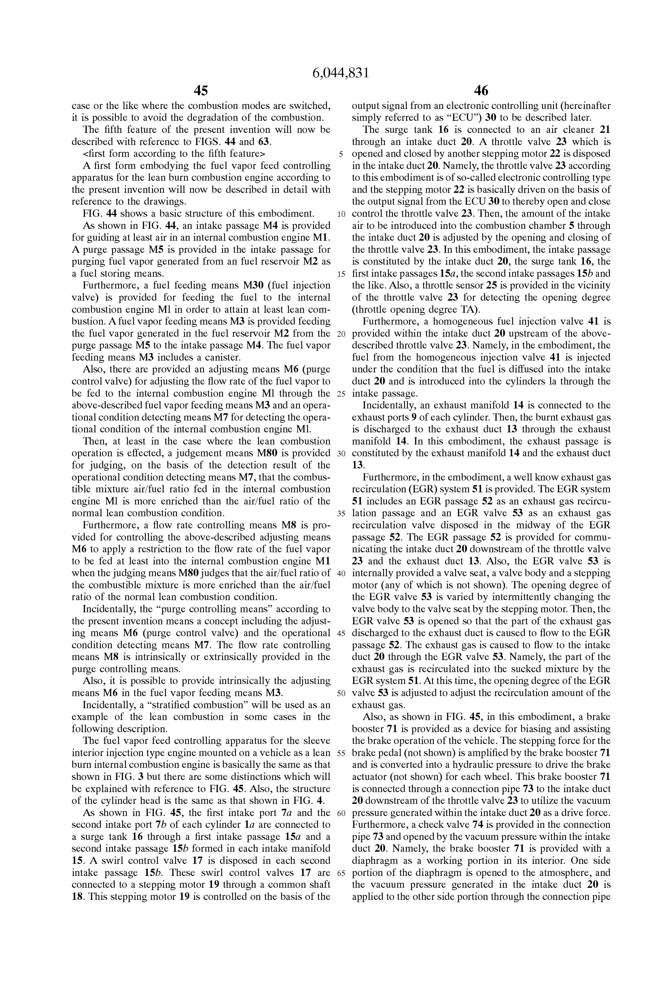
Page 82
73. The connection pipe 73 is provided with a pressure Incidentally, the above-described count is incremented by Sensor 72 as a vacuum pressure detecting means for detect one in response to the load and the engine revolution Speed. ing a brake booster internal pressure (absolute pressure). When the count value reaches the predetermined value, the Furthermore, in this embodiment, a nitrogen oxide rich Spike control is executed. Also, after the completion of absorbing reducing catalyst 61 is provided as a nitrogen the rich Spike control, the above-described count value is oxide reducing catalyst within the exhaust duct 13. This cleared to Zero. Then, the same process is repeated. catalyst 61 is used to purifying NOx which is liable to be An example of the control routine of an NOx discharged generated in the lean air/fuel ratio region and basically flag is shown in FIG. 47. This routine is executed by an absorbs the NOx contained in the exhaust gas when the interrupt at a constant time interval. operation is effected at the lean air/fuel ratio. Also, if the First of all, in step 50, it is judged whether or not the air/fuel ratio is controlled to be enriched, the amounts of the compensation coefficient L is less than 1.0, that is, the lean reducing agents Such as HC and CO in the exhaust gas are mixture is burnt. When L21.0, that is; the mixture fed into increased so that the NOx absorbed therein is released from the catalyst and at the same time, the NOx is reduced to the the combustion chamber is in the Stoichiometric ratio or on nitrogen gas on the catalyst to be discharged into the the rich side, the process shifts to step 56. The NOx release atmosphere. 15 flag is reset. Subsequently, in Step 57, the count value C is The above-described NOx absorbing reducing catalyst 61 Zero, and in the same manner, in Step 58, the count Value D is, for example, an aluminum carrier for carrying thereon a is Zero.
noble metal Such as platinum Pt and at least one Selected In contrast, if, in step 50, it is judged that L-1.0, that is; from the groups of alkaline metal Such as kalium K, Sodium the lean combustion is effected, the process shifts to step 51 Na, lithium Li, and cesium Cs, alkaline earth metal Such as in which the count value C is incremented by one. barium Ba and calcium Ca, rare earth metal Such as lantha Subsequently, in Step 52, it is judged whether or not the num and yttrium. count Value C exceeds a constant value Co. If C>Co, the The NOX absorbing reducing catalyst has the character process shifts to step 53 in which the NOx discharge flag is istics that, when an air excessive rate 2 of the exhaust gas is reset. Subsequently, in Step 54, the count Value D is incre larger than 1 (lean), it may adsorb NOx (NO and NO) 25 mented by one. Subsequently, in Step 55, it is judged contained in the exhaust gas is absorbed in the form of whether or not the count value D exceeds a constant value nitrate ion NO. Do. If D >Do, the process shifts to step 56 in which the NOx More specifically, the explanation will be given as to an discharge flag is Set. Namely, if a constant time, for example, example in which platinum Pt and barium Ba are carried on 5 minutes, lapses until the lean mixture combustion is a carrier. If the oxygen concentration in the flowing exhaust expressed by C>C, the NOx release flag is set. Thereafter gas is high to the catalyst (that is, the air excessive rate 2 of a constant time, for example, 5 minutes, lapses until the the exhaust gas is larger than 1 (lean)), the oxygen is adhered relationship DD is established, the NOx release flag is to the Surface of the platinum Pt in the form of O or O. continuously set. When the NOX discharge flag is set, the on the platinum Pt, and NO in the exhaust gas reacts with mixture fed to the combustion chamber of each engine O or O on the platinum Pt surface to become NO 35 cylinder is enriched.
(2NO+O=2NOM). Also, NO contained in the exhaust gas Subsequently, the purge controlling unit 81 as the fuel and NO produced as described above are further oxidized Vapor feeding means mounted for feeding the fuel vapor into on the platinum Pt and absorbed into the absorbent to be the intake duct will be described.
bonded with BaO and to be diffused into the NOx absorption As shown in FIG. 45, the purge control unit 81 is provided agent in the form of nitrate ion NO. For this reason, under 40 with the canister 83 having an activated charcoal layer 82. the condition of 2d 1.0, NOx contained in the exhaust gas is A fuel vapor chamber 84 and an air chamber 85 are formed absorbed into the Nox absorbing reducing catalyst. on both sides of the activated charcoal layer 82 within the Also, when the oxygen concentration in the flowing canister 83.
exhaust gas is largely reduced (that is, the air excessive rate A part of the fuel vapor chamber 84 is formed in an upper 2 of the exhaust gas is equal to or less than 1 (rich)), the 45 Space of the fuel tank 89 through a Solenoid opening/closing amount of the production of the NO on the platinum Pt is valve 87, and the other part is connected to the intake duct decreased, So that the reaction is developed in the reverse 20 downstream of the throttle valve 23 through the purge direction. The nitrate ion NO in the absorbent is released controlling valve 86 composed of a solenoid valve as the from the NOx absorbent in the form of NO and NO. In this adjusting means and a throttle valve 90 for allowing the flow case, if the reduced components Such as HC and CO are 50 only in the direction toward the intake duct 20 to the fuel present in the exhaust gas, NO is reduced by these com vapor chamber 84.
ponents on the platinum Pt. Also, the air chamber 85 is in communication with an air In this embodiment, such an NOx absorbing reducing intake inlet 91 in the intake duct 20 upstream of the throttle catalyst 61 is utilized to effect a well known "rich spike valve 23. The upper space of the fuel reservoir 89 is control”. Namely, if the operation is continued at the lean 55 connected the interior of the intake duct downstream of the air/fuel ratio, NOx absorbed to the above-described catalyst air intake inlet 91 and upstream of the throttle valve 23. A 61 is Saturated as described above, and there is a fear that the preSSure Sensor 92 is mounted on the upper Space of the fuel excess of NOx would be discharged while contained in the reservoir 89.
exhaust gas. As described above, the air intake inlet 91 is opened to the Accordingly, in this control, the closing control of the 60 upstream Side of the intake air flow. Accordingly, a dynamic throttle valve 23 by the ECU 30 is performed, and the preSSure is applied to the air intake inlet 91. Accordingly, the air/fuel ratio is temporarily forcibly controlled to be pressure within the canister 83 is somewhat higher than the enriched in View of a predetermined timing judged by a atmospheric pressure. On the other hand, the Solenoid valve count value of the rich Spike condition establishing counter. 87 is opened. At this time, if the pressure of the upper space With Such a control, the amount of HC contained in the 65 of the fuel reservoir 89 is higher than the pressure within the exhaust gas is increased, and the NOX is reduced to the canister 83, the fuel vapor generated in the fuel reservoir 89 nitrogen gas to be discharged into the atmosphere. is caused to flow into the fuel vapor chamber 84 through the
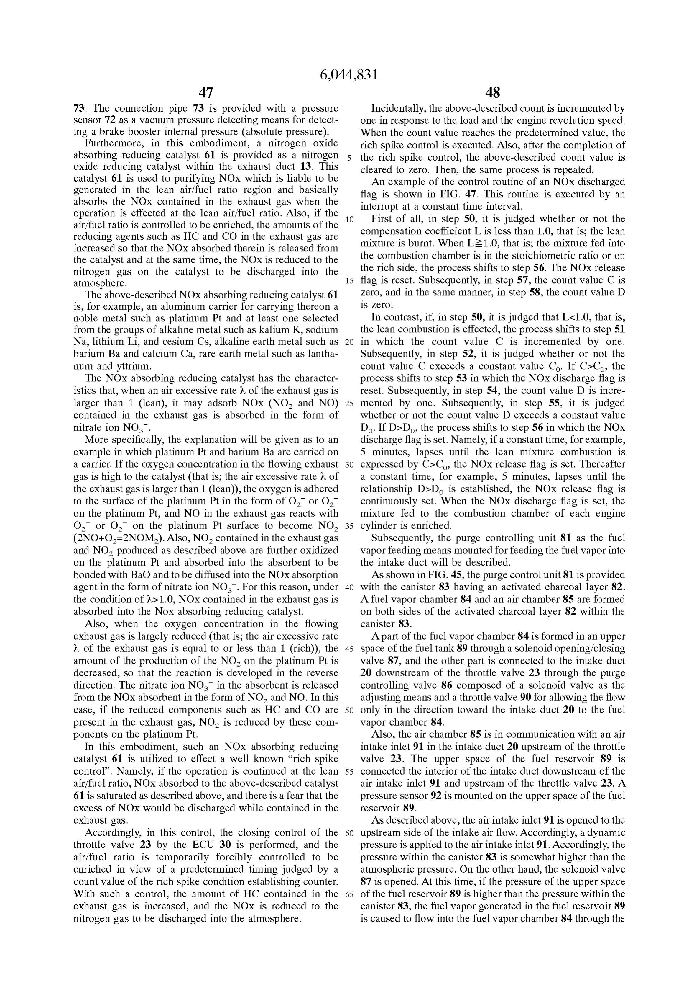
Page 83
49 SO
Solenoid opening/closing valve 87. Subsequently, the fuel Furthermore, the rotational angle of the above-described vapor is absorbed into the activated charcoal within the shaft 18 is detected by a Swirl control valve sensor 29 by activated charcoal layer 82. When the Solenoid valve 86 is which the opening degree of the Swirl control valve 17 may opened, the air that has introduced into the air intake inlet 91 be detected. Then, the output of the Swirl control valve is fed into the air chamber 85 and subsequently, the air is fed sensor 29 is inputted into the input port 35 through the A/D to the activated charcoal layer 82. convertor 37.
The fuel that has been absorbed in the activated charcoal In addition, the throttle opening degree TA is detected by is released, and the air containing the fuel component is the throttle sensor 25. The output of the throttle sensor 25 is caused to flow into the fuel vapor chamber 84. Subsequently, inputted into the input port 35 through the A/D convertor 37. the air including the fuel component is fed into the intake 46 is providedin for
In addition, this embodiment, an intake pressure Sensor duct 20 through the check valve 90 and the Solenoid within the Surge tankdetecting 16.
a pressure (intake pressure)
Furthermore, a water temperature opening/closing valve 86. In the embodiment, the throttle Sensor 47 is provided for detecting a temperature of cooling Valve 23 is maintained in the fully opened condition except water for the engine 1 (cooling water temperature). Also, the for the extremely low load mode in the stratified combus oxygen Sensor 62 is provided in the exhaust duct 13. Also, tion. Even if the throttle valve 23 is thus substantially in the 15 the outputs of these sensors 46, 47 and 62 are inputted into fully opened condition, the dynamic pressure is applied to the input port 35 through the A/D convertor 37. the air intake inlet 91 so that the fuel vapor may be fed into In this embodiment, the operational condition detecting the intake duct 20. means is constituted by the throttle Sensor 25, the accelerator On the other hand, if the Solenoid opening/closing valve sensor 26A, the fully closed switch 26B, the top dead center 88 is opened and the pressure of the upper space of the fuel sensor 27, the crank angle sensor 28, the Swirl control valve reservoir 89 at this time is higher than the atmospheric Sensor 29, the intake preSSure Sensor 46, the water tempera pressure, the fuel vapor generated in the fuel reservoir 89 is ture Sensor 47, the oxygen Sensor 62, pressure Sensors 72 fed to the intake duct 20 through the Solenoid opening/ and 92 and the like.
closing valve 88. Incidentally, in this embodiment, the On the other hand, connected through the associated Solenoid opening/closing valve 88 is opened when the 25 driver circuit to the output port 36 are the respective fuel pressure in the upper space of the fuel tank 89 is not at the injection Valves 11 and 41, the respective Stepping motorS 19 atmospheric pressure but Somewhat higher than the atmo and 22, the ignitor 12, the EGR valve 53 (stepping motor), Spheric preSSure. the respective Solenoid opening/closing valves 86 to 88 and Also, in the above-described embodiment, if the Solenoid So on. The fuel injection valves 11 and 41, the Stepping opening/closing valve 86 is opened, the fuel vapor absorbed motors 19 and 22, the ignitor 12, the EGR valve 53 (stepping in the activated charcoal layer 82 of the canister 83 is fed motor), the respective solenoid valves 86 to 88 and the like into the intake duct 20, and if the Solenoid opening/closing are Suitable controlled in accordance with the control pro valve 88 is opened, the fuel vapor generated in the fuel tank gram Stored in the ROM 33 on the basis of the signals of 89 is fed into the intake duct 20. Thus, in this embodiment, respective sensors and the like 25 to 29, 46, 47, 62,72 and the fuel vapor may be fed not only from the canister 83 but 35 92 by the ECU 30.
also from the fuel reservoir 89 into the intake duct 20. The programs for the various controls in the fuel vapor By the way, as shown in FIGS. 45 and 46, the above feed controlling apparatus for the engine provided with the described ECU 30 is composed of a digital computer pro above-described Structure in accordance with the first vided with a RAM (random access memory) 32, a ROM embodiment will now be described with reference to the (read only memory) 33, a CPU (central processing unit) 34 40 flowchart shown in FIG. 48.
composed of a microprocessor, an input port 35 and an Namely, FIG. 48 is a flowchart showing a “fuel vapor feed output port 36 connected to each other through a two-way controlling routine’ for controlling the purge and executing buS 31. In this embodiment, the judgement means and fuel the control of the fuel vapor fed to the intake duct by controlling means are constituted by the ECU 30. controlling the Solenoid opening/closing valve 86 accord An accelerator Sensor 26A is connected to an accelerator 45 ing to this embodiment. This control is executed by the pedal 24 of the vehicle for generating an output Voltage in above-described ECU 30. This example executes the feature proportion to a Step amount of the accelerator pedal 24. An of item (6-1).
accelerator opening degree ACCP is detected by the accel Incidentally, if the purge execution conditions: for erator Sensor 26. The output voltage of the accelerator Sensor example, i) the warming-up completion; ii) the State where 26A is inputted into the input port 35 through an AD 50 a predetermined time has lapsed after the start; and iii) the convertor. A fully closed switch 26B is provided to the State where the fuel injection amount is equal to or more than accelerator pedal 24 for detecting the condition that the Step the minimum fuel injection amount for establishing the amount of the accelerator pedal 24 is zero. Namely, the fully combustion are all met, the purge execution flag is turned on closed switch 26B generate a “1” signal as a fully closed to Start the purge.
Signal. in the case where the Step amount of the accelerator 55 Then, in case of the duty control System, the opening pedal 24 is Zero and generates a Zero Signal in other cases. degree of the Solenoid opening/closing valve 86 for control Then, the output voltage of the fully closed Switch 26B is ling the purge amount is gradually increased from the duty inputted into the input port 35. ratio of 0% (fully closed) to the duty ratio corresponding to Also, for example, a top dead center Sensor 27 generates the engine operational condition (fuel injection amount). an output pulse when the piston of the first cylinder la 60 Then, if the purge prohibition condition, for example, fuel reaches the intake top dead center. This output pulse is interrupt execution or the like is met, the purge is inter inputted into the input port 35. A crank angle Sensor 28 rupted.
generates an output pulse through every 30 CA rotation of Also, Since the fuel vapor is fed to the internal combustion the crankshaft. This output pulse is inputted into the input engine by the purge, the fuel injection amount to be fed to port. The CPU 34 calculates the engine revolution speed NE 65 the internal combustion engine is compensated for by the (or read in) from the output pulse of the top dead center fuel vapor compensation amount FPG corresponding to the Sensor 27 and the output pulse of the crank angle Sensor 28. fuel vapor to be fed.
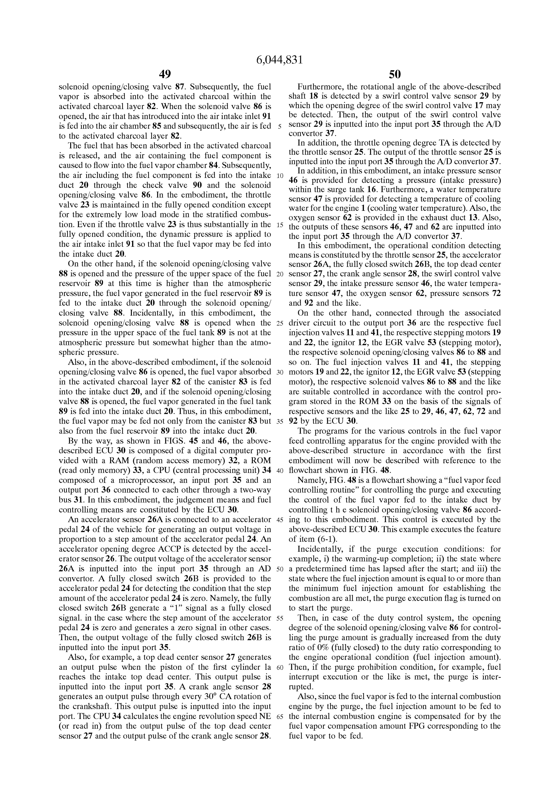
Page 84
S1 52
Namely, final fuel injection amount QALLINJ=basic fuel injectionIn step 104, it is judged whether or not the above amount QALL-fuel vapor amount compensation amount described duty ratio DPG is zero. In the case where it is FPG--K formula (1).
judged that the above-described duty ratio DPG is not zero, where K is the variety of compensation coefficients Such as the process thereafter is once Stopped. Namely, So far as the the warming-up increment coefficient, the acceleration feed of the fuel vapor is not stopped by the step 103 process, increment coefficient, the deceleration compensation coef the opening degree of the Solenoid opening/closing valve 86 ficient and the reducing agent amount coefficient to be is controlled on the basis of the duty ratio DPG obtained in described later.
With such prerequisites, the process shown in FIG. 48 will stepOn103 to control the feed of the fuel vapor. the other hand, in step 104, it is judged that the now be described.
In the purge control, in the process shown in FIG. 48, first above-described duty ratio DPG is zero, the process shifts to of all, the engine revolution Speed NE and the accelerator step 105. In step 105, the execution of the rich spike control opening degree ACA are inputted in to ECU 30 (step 90). is allowed. Namely, after it is confirmed that the feed of the Subsequently, the basic fuel injection amount QALL is fuel vapor is stopped, the rich Spike control is executed. calculated in accordance with the inputted engine revolution Thereafter, in step 108, the fuel vapor amount compen Speed and accelerator opening degree (step 91). 15 sation amount is converted from the duty ratio. Namely, Namely, first of all, the basic fuel injection amount since the purge amount is determined by the intake pipe corresponding to the engine revolution Speed and the accel Vacuum ab -pressure and the opening degree of the purge erator opening degree is complementarlly calculated from a control valve determined by the duty ratio, if the fuel vapor map for determining the mutual relationship between the concentration in the purge gas is known, the fuel vapor engine revolution speed and the accelerator opening degree. amount is known. Since this fuel vapor amount is fed to the Incidentally, a plurality of maps are prepared in correspon internal combustion engine, in step 109, the fuel vapor dence with the operational condition or combustion condi amount is Subtracted from the predetermined basic fuel tion. One is Selectively used from the maps. injection amount as the compensation amount in accordance In Step 92, it is judged whether the purge is effected. If So, with the following formula (1):
in step 101, it is judged whether or not the rich spike control 25 final fuel injection amount QALLINJ=basic fuel injection is currently effected. Then, in the case where it is judged that amount QALL-fuel vapor amount compensation the rich Spike control is executed, it is judged that the feed amount FPG+K0... (1) where KO the reducer amount of the fuel vapor is not suitable. In step 106, the duty ratio coefficient determingin the amount of the reducer (HC) DPG corresponding to the opening degree of the Solenoid opening/closing valve 86 is made Zero to once complete the needed for purifying NOx. Thus, the fuel injection process thereafter. Namely, in the case where it is judged that amount to be finally fed to the internal combustion the rich Spike control is executed, the fuel vapor Supply is engine is compensated for. interrupted. Incidentally, in the case where, in Step 92, it is judged that On the other hand, in step 101, in the case where it is the purge is not effected, in Step 93, the fuel vapor amount judged that the rich Spike control is not currently effected, compensation amount is Zero and the final fuel injection the process shifts to step 102. It is judged whether or not the 35 amount QALLINJ is the basic fuel injection amount QALL+ count value of the rich Spike condition establishment counter KO. Thereafter, the fuel injection is performed in accordance exceeds a predetermined value Co Set in advance. The rich with the fuel injection program determined separately. Spike condition establishment counter value is counted by Subsequently, the effect and operation of the embodiment the ECU 30 on the basis of the predetermined conditions in will be described.
accordance with the flowchart shown in FIG. 47 as men 40 (a) In this embodiment, when NOx to be trapped by the tioned above. It is reset after the completion of the rich spike catalyst 61 is Saturated in the Stratified combustion, in order control and is recounted. It is judged that the count Value of to forcibly release and purify the NOx, the rich spike control the rich Spike condition establishment counter is equal to or is executed. At this time, the throttle valve 23 is temporarily less than the predetermined value Co, the duty ratio DPG is closed, the air/fuel ratio is close to the Stoichiometric aff calculated in step 107 on the basis of the differential pressure 45 ratio or more enriched. For this, ECU 30 reduces the duty dp between the atmospheric pressure and the pressure within ratio DPG, and made it Zero thereafter by controlling the the intake duct 20. opening degree of the Solenoid opening/closing valve 86 So Incidentally, the function f used in this calculation is that the fuel Vapor to be fed from the purge controlling unit conventionally adopted corresponding to the differential 81 to the intake duct 20 is reduced or interrupted. For this pressure dip. The flow rate of the fuel vapor is controlled by 50 reason, in the rich Spike control, it is possible to moderate the opening degree of the Solenoid opening/closing valve 86 the adverse affect given to the air/fuel ratio by the fuel vapor. in accordance with the calculation result. Also, the intake Accordingly, the air/fuel ratio is well controlled and would preSSure obtained by the intake pressure Sensor 46 in, for not be disturbed. As a result, it is possible to prevent the example, the engine Start is recorded and utilized as the generation of the rich misfire or the like, which leads to the atmospheric pressure for calculating the differential pressure 55 maintenance of the good drivability. dp. On the other hand, the intake pressure obtained by the (b) Also, ECU 30 measures the start timing of the rich intake Sensor 46 is utilized as the pressure of the intake duct Spike control from the count value of the rich Spike control 20 every time. establishment counter, and gradually decreases the duty ratio Also, in Step 102, it is judged that the count Value of the DPG before the execution of the rich spike control. For this rich Spike condition establishment counter exceeds the pre 60 reason, it is possible to prevent the abrupt variation of the determined value Co, for a while, it is inferred that the rich air/fuel ratio before and after the start of the rich spike spike control is effected. The process shifts to step 103. In control. Accordingly, it is possible to further ensure the step 103, a predetermined value C. is subtracted from the effect (a) above.
previous duty ratio DPG. Namely, the Solenoid opening/ Incidentally, in the first embodiment, the predetermined closing valve 86 is gradually decreased to reduce the flow 65 value C. for the duty ratio DPG in step 103 is constant. rate of the fuel vapor. Thereafter, the process shifts to Step However, it is possible to use the variable in response to the 104. operational condition.
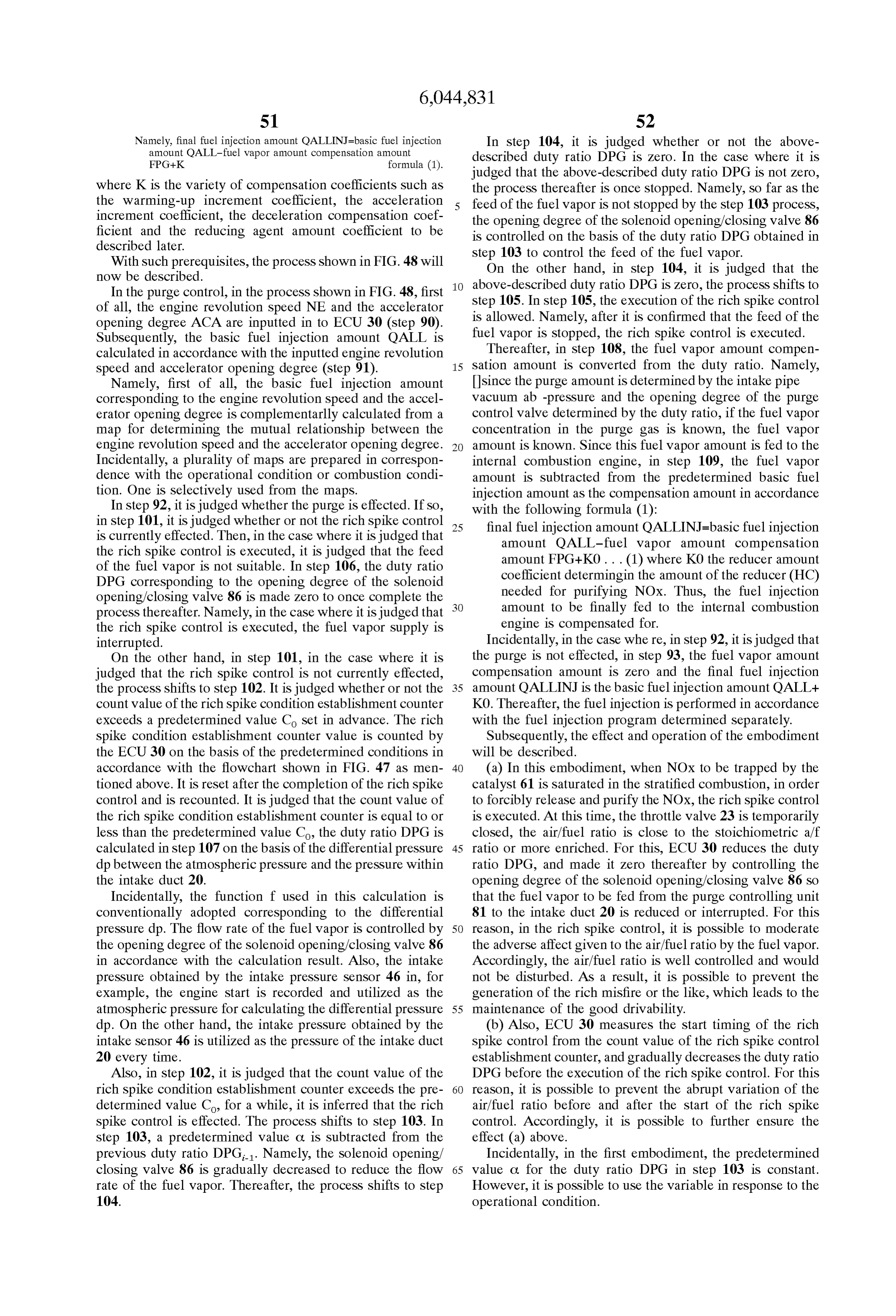
Page 85
S3 S4
Also, in the first embodiment, the reduction of the pre rarily closed, the air/fuel ratio is close to the Stoichiometric determined value C. for the duty ratio DPG in step 103 is a/fratio or more enriched. For this, ECU30 reduces the duty repeated to gradually reduce the duty ratio DPG down to ratio DPG, and made it Zero thereafter by controlling the Zero. It is possible to make the duty ratio DPG Zero at once. opening degree of the Solenoid opening/closing valve 86 So <Second form according to the fifth feature> that the fuel Vapor to be fed from the purge controlling unit A Second form embodying the present invention will now 81 to the intake duct 20 is reduced or interrupted. For this be described. However, the structure or the like is Substan reason, in the rich Spike control, it is possible to moderate tially the same as that of the first form of the invention. Its the adverse affect given to the air/fuel ratio by the fuel vapor. explanation will be omitted. The difference therebetween Accordingly, the air/fuel ratio is well controlled and would will be described. This example executes the features of not be disturbed. As a result, it is possible to prevent the (6–2) and (6-3). generation of the rich misfire or the like, which leads to the In the first form, the execution condition of the rich spike maintenance of the good drivability. control is judged, and the Solenoid opening/closing valve 86 In particular, in the sleeve interior injection type internal is controlled on the basis of the judgement result to thereby combustion engine, Since the throttle valve is normally control the fuel vapor to be fed to the intake duct 20. In 15 operated at a full throttle in many cases, when the brake is contrast, in this embodiment, when the vacuum pressure of effected, the brake booster vacuum pressure has to be the intake duct 20 is increased and the intake amount is generated every time. The production of the vacuum pres throttled so that the vacuum pressure within the brake Sure is attained by temporarily closing the throttle valve. booster 71 may be produced and maintained. In this However, in this case, the air/fuel ratio is temporarily condition, it is characterized in that the above-described fuel enriched to bring about a fear of misfire. Accordingly, in Vapor amount is controlled. Such a case, as described above, the feed of the fuel vapor FIG. 49 is a flowchart showing a “fuel vapor control is restricted to thereby prevent the misfire. Thus, this routine' for executing the control of the fuel vapor in this example is very effective for the sleeve interior injection embodiment, and to be executed by ECU 30 instead of the type internal combustion engine.
steps 101 to step 107 shown in FIG. 48 as a main routine. 25 In the second embodiment, the duty ratio DPG is made When the process shifts to this routine, first of all, ECU Zero at once in Step 203. However, it may gradually reduce 30 judges in step 201 whether or not the brake control is the duty ratio DPG. If it is reduced gradually, it is possible currently effected. Then, in the case where it is judged that to SuppreSS the abrupt combustion change upon Switching. the brake control is effected, it is judged that the feed of the The vacuum pressure production means is made by an fuel vapor is not suitable. In step 203, the duty ratio DPG is electronic type throttle mechanism composed of the throttle made Zero to once complete the process thereafter. Namely, valve 23 provided in the intake duct 20 and the stepping in the case where it is judged that the brake control is motor 22 as an actuator for opening/closing the throttle executed, the fuel Vapor Supply is interrupted. valve 23. However, as another modification, this may be On the other hand, in step 201, in the case where it is made by an ISC mechanism composed of an idle Speed judged that the brake control is not currently effected, the 35 control valve provided in a bypass passage around the process shifts to step 202. In step 202, it is judged whether throttle valve 23 and an actuator for opening/closing the ISC or not the brake vacuum preSSure exceeds a predetermined valve.
value BkPa (absolute value) set in advance. In this case, the Also, the EGR device 51 provided with the above predetermined BkPa means the value at which the brake described EGR valve 53 or the like may be used. Vacuum maintenance proceSS is executed in the case where 40 Furthermore, a vacuum preSSure producing mechanism the brake Vacuum pressure becomes the above-described (not shown) may be discretely provided. In these cases, a value +a constant value. If it is judged that the brake vacuum mechanical type throttle Valve linked to the accelerator pedal pressure exceeds the predetermined value BkPa, in step 204, 24 may be used instead of the So-called electronic control the duty ratio DPG is calculated on the basis of the above type throttle valve 23.
described differential pressure dip to once finish the proceSS 45 Furthermore, these mechanisms may be combined thereafter. Namely, the duty ratio DPG is calculated as a together to form the vacuum production means. function g of the differential pressure dp. The flow rate of the <third form according to the fifth feature> fuel vapor is controlled by the opening degree of the A third form embodying the present invention will now be Solenoid opening/closing Valve 86 in accordance with the described. However, the structure or the like is substantially calculation result. 50 the same as that of the first form of the invention. Its Also, in Step 202, in the case where it is judged that the explanation will be omitted. The difference therebetween brake Vacuum pressure is equal to or less than the above will mainly be described.
described predetermined value BkPa, it is inferred that, for In the first form, the execution condition of the rich spike a while, a process for maintaining the brake Vacuum pres control is judged, and the Solenoid opening/closing valve 86 Sure (process for temporarily closing the throttle valve 23 55 is controlled on the basis of the judgement result to thereby and enriching the air/fuel ratio close to the Stoichiometric control the fuel vapor to be fed to the intake duct 20. In air/fuel ratio) is executed. In step 203, the duty ratio DPG is contrast, in this embodiment, the reduction of the intake made Zero and the process thereafter is once Stopped. density in, for example, a high land is detected by the output Namely, in the case where it is judged that the brake Vacuum of the intake pressure sensor 46 to thereby control the fuel preSSure maintenance proceSS will be executed Soon, the fuel 60 vapor. This example executes the feature of (6-4). Vapor feed is interrupted. FIG. 50 is a flowchart showing a “fuel vapor control The effect and operation of this embodiment will now be routine' for executing the control of the fuel vapor in this described. embodiment, and to be executed by ECU 30 instead of the (a) In this embodiment, when the vacuum pressure within steps 101 to step 107 shown in FIG. 48 as a main routine. the brake booster 71 for assisting the brake operation by the 65 When the process shifts to this routine, first of all, ECU Vacuum pressure is insufficient, the brake vacuum pressure 30 judges in step 301 whether or not the atmospheric is maintained. At this time, the throttle valve 23 is tempo preSSure is higher than a predetermined value CkPa Set in
Page 86
SS S6 advance. Then, in the case where it is judged that the complementarly calculated in accordance with the inputted atmospheric pressure exceeds the above-described predeter engine revolution Speed and accelerator opening degree mined value CkPa, in step 303, the duty ratio DPG is (step 682).
calculated on the basis of the differential pressure dip to once Namely, the basic fuel injection amount corresponding to Stop the process thereafter. Namely, it is judged that the the engine revolution Speed and the accelerator opening reduction of the intake density is not effected, and the as degree is complementarily calculated from a map (not usual, the duty ratio DPG is calculated as a function h of the shown) for determining the mutual relationship between the differential pressure dip. The opening degree of the Solenoid engine revolution Speed and the accelerator opening degree. opening/closing valve 86 is controlled on the basis of the In step 683, it is judged whether or not the purge is result, so that the flow rate of the fuel vapor is controlled. effected. If it is in the purge, the throttle Valve opening Also, in Step 301, it is judged that the atmospheric degree TA and the engine revolution Speed NE are read in preSSure is equal to or less than the above-described prede (step 684).
termined value CkPa, the value obtained by multiplying the Next, the fuel vapor amount compensation amount (FPG) previous duty ratio DPG by a compensation coefficient B is calculated (step 685). This calculation is effected from the (0s Bs1) obtained from the correspondence with the atmo 15 mutual relationship (see FIG. 53) between the fuel vapor spheric pressure shown in FIG. 51 is set as a new duty ratio amount compensation amount (FPG) and the throttle valve DPG. The process thereafter is once stopped. Namely, opening degree TA and the engine revolution speed NE through this step 302, the duty ratio DPG is gradually stored in the ROM in the form of a map in advance. reduced. Incidentally, in FIG. 53, HIGH, INTERMEDIATE and The effect and operation of this embodiment will now be LOW are drawn to the engine revolution speeds. The smaller described. the engine revolution Speed, the more the fuel vapor amount (a) In this embodiment, in the stratified combustion compensation amount will become. condition, Since the air density (intake density) is low in a In the case where, in step 683, the operation is out of the high land, the air/fuel ratio is likely to be enriched in purge, in Step 687, the fuel vapor amount compensation comparison with the low land. For this, when the atmo 25 amount is Zero.
spheric pressure is low (air density is low), ECU30 reduces After the fuel vapor amount compensation amount FPG is the duty ratio DPG, and made it Zero thereafter by control determined in steps 685 and 687, the process shifts to step ling the opening degree of the Solenoid opening/closing 686 to determine the final fuel injection amount QALLINJ. valve 86 so that the fuel vapor to be fed from the purge In this case, the final fuel injection amount QALLINJ is controlling unit 81 to the intake duct 20 is reduced or determined by Subtracting the fuel vapor amount compen interrupted. For this reason, in the high land, it is possible to sation amount FPG from the basic fuel injection amount moderate the adverse affect given to the air/fuel ratio by the QALL calculated in advance in Step 682 and adding the fuel vapor. Accordingly, the air/fuel ratio is well controlled compensation coefficient K.
and would not be disturbed. As a result, it is possible to Thereafter, the fuel injection is effected in accordance prevent the generation of the rich misfire or the like, which 35 with the fuel injection program determined separately. leads to the maintenance of the good drivability. Incidentally, other calculation methods of the fuel vapor In the third embodiment, as shown in FIG. 51, the value amount compensation amount (FPG) are typically exempli of the compensation coefficient X is changed in a linear fied as a method for obtaining it from the purge gas amount manner corresponding to the atmospheric pressure. Qp as shown in FIG. 54 and a method for obtaining it from However, any other desired curve may be used if it has 40 the intake manifold pressure as shown in FIG. 55. characteristics gradually increasing up to the predetermined Incidentally, the routine shown in FIG. 52 is repeatedly value CkPa corresponding to the atmospheric pressure. executed at a predetermined time interval. <forth form of the fifth feature> Since the fuel Vapor compensation amount is detected by In the fourth form, the control by the fuel vapor compen such a routine, particularly, steps 684 and 685, a large sation amount FPG is added in accordance with the above 45 amount of fuel vapor may be processed without any adverse described formula (1) to the control of DPG in the first affect to the drivability or the emission. embodiment in order to compensate for the basic fuel By the way, there are cases where the air/fuel ratio is injection amount. enriched in an abrupt manner according to an operational When the purge control valve is controlled by controlling condition during the purge control shown in FIG. 52. If the DPG and the purge amount is controlled in the increment 50 fuel vapor is continued to be Supplied in Such a case, an direction, the fuel vapor amount to be added to the basic fuel enriched air/fuel ratio is temporarily established exceeding injection amount is increased. Accordingly, if no counter the necessary level. Therefore, there is a fear of misfire or the measure is effected, in Some cases, the air/fuel ratio is too like.
excessive. Accordingly, the fuel vapor amount compensa Therefore, as described below, the condition in which the tion amount FPG is obtained corresponding to the increment 55 air/fuel ratio is abruptly enriched is inferred by the judge of the DPG so that the fuel vapor amount compensation ment means, the fuel injection amount from the fuel injec amount FPG is reduced from the basic fuel injection amount tion valve is limited simultaneously with the feed of the fuel to be injected from the fuel injection valve to avoid the Vapor or the restriction of the fuel vapor. abrupt enriched condition. An example of controlling FPG will now be described Subsequently, an example of the fuel injection control 60 with reference to FIG. 56. This executes the feature of (6-1). including a purge control of this embodiment will be The FPG control may be used together with the DPG control described with reference to a flowchart shown in FIG. 52. as described above.
This is an example to compensate for the fuel vapor amount When the process shifts to this routine, first of all, ECU in correspondence with the engine revolution speed. 30 judges in step 1101 whether or not the rich spike control First of all, the engine revolution speed NE and the 65 is currently effected. Then, in the case where it is judged that accelerator opening degree ACA are inputted (step 681). the rich Spike control is effected, it is judged that the feed of Subsequently, the basic fuel injection amount QALL is the fuel vapor is not suitable. In step 1106, the fuel vapor
Page 87
compensation amount FPG is made Zero to once complete 61(4) shows the change of the air/fuel ratio before and after. the process thereafter. Namely, in the case where it is judged the rich Spike in the conventional purge execution and shows that the rich Spike control is executed, the final injection fuel that a condition in which the air/fuel ratio is shifted to a amount is the Sum of the basic injection fuel amount and KO richer air/fuel ratio than the necessary air/fuel ratio by the (where KO is the reducer amount coefficient determining the affect of the purge against the necessary air/fuel ratio before amount of the reducer (HC) needed for purifying NOx) in the rich Spike is continued. If the rich Spike is executed under accordance with the above-described formula (1). the condition that the air/fuel ratio is deviated from the On the other hand, in step 1101, in the case where it is required air/fuel ratio without any change, the air/fuel ratio judged that the rich Spike control is not currently effected, is kept in the condition that it is richer than that correspond the process shifts to step 1102. It isjudged whether or not the ing to the rich Spike. Finally, there is a fear that the rich count value of the rich Spike condition establishment counter misfire would occur.
exceeds a predetermined value Co Set in advance. The rich On the other hand, FIG. 61(3) shows a case where the Spike condition establishment counter value is counted by DPG is only controlled in accordance with the embodiment. the ECU 30 on the basis of the predetermined conditions in The DPG is gradually changed to the air/fuel ratio required accordance with the flowchart shown in FIG. 47 as men 15 by the condition in which the air/fuel ratio is richer than the tioned above. It is reset after the completion of the rich spike necessary air/fuel ratio, by gradually Subtracting it until the control and is recounted. It is judged that the count Value of rich Spike is executed. As a result, when the rich Spike is the rich Spike condition establishment counter is equal to or executed, it may meet the air/fuel ratio corresponding to the less than the predetermined value Co, the duty ration DPG rich Spike. Accordingly, it is possible to prevent the genera is calculated in step 1107 on the basis of the differential tion of the rich misfire. Also, since the DPG is gradually preSSure dip between the atmospheric pressure and the pres Subtracted, it is possible to SuppreSS the turbulence of the sure within the intake duct 20. The precess thereafter is once air/fuel ratio to stabilize the combustion. Furthermore, since Stopped. the DPG is gradually Subtracted, the purge execution time is Incidentally, the function f used in this calculation is longer than that of the method in which the DPG is abruptly conventionally adopted corresponding to the differential 25 decreased and the air/fuel ratio is identified with the neces preSSure dip. The intake preSSure obtained by the intake sary air/fuel ration. It is therefore possible to sufficiently preSSure Sensor 46 in, for example, the engine Start is keep the purge amount.
recorded and utilized as the atmospheric pressure for cal Next, FIG. 61(2) corresponds to the embodiment shown culating the differential pressure dip. On the other hand, the in FIG. 56 and shows a case where the DPG and FPG are intake preSSure obtained by the intake Sensor 46 is utilized gradually subtracted to be close to Zero. If the DPg is as the pressure of the intake duct 20 every time. Then, the Subtracted, the air/fuel ratio is shifted on the lean Side, fuel injection amount is controlled in accordance with the whereas the FPG is Subtracted, the air/fuel ratio is shifted on fuel vapor compensation amount on the basis of the equation the rich side. Accordingly, it is possible to identify the FPG=f(dp) calculated. air/fuel ratio with the necessary air/fuel ratio if the DPG and Also, in step 1102, it is judged that the count value of the 35 FPG are subtracted in synchronism with each other. rich Spike condition establishment counter exceeds the pre Thus, according to the form of this embodiment, in a determined value Co, for a while, it is inferred that the rich synergy with the DPG control, it is possible to identify the spike control is effected. The process shifts to step 1103. In air/fuel ratio with the necessary air/fuel ration in the period step 1103, a predetermined value C. is subtracted from the until the execution of the rich Spike. In the rich Spike control, previous duty ratio DPG. 40 the affect given to the air/fuel ratio by the fuel vapor is The fact that FPG is reduced in comparison with the reduced. Accordingly, the air/fuel ratio is well controlled and previous one means that the fuel injection amount to be there is no turbulence. As a result, it is possible to prevent finally fed to the engine is increased, according to the the generation of the rich misfire or the like. Finally, it is formula (1). Thereafter, the process shifts to step 1104. possible to maintain the drivability. In the meanwhile, as is apparent from FIG. 61(2), the 45 Incidentally, in the fourth embodiment of the invention, DPG is gradually reduced and directed in the lean direction, the predetermined value C. of the FPG which is to be and the FPG is gradually reduced and directed in the rich Subtracted is the constant value. It is possible to use a direction. Accordingly, the air/fuel ratio is kept at the variable in response to the operation condition. required value. Also, in the fourth embodiment, in step 1103, the Sub In step 1104, it is judged whether or not the above 50 traction of the predetermined value C. from the FPG is described duty ratio FPG is zero. In the case where it is repeated and the FPG is gradually reduced down to zero. judged that the above-described duty ratio FPG is not zero, However, it is possible to make the FPG Zero at once. the process thereafter is once Stopped. The final fuel injec <fifth form of fifth feature> tion amount is increased on the basis of the FPG obtained in A fifth form embodying the present invention will now be step 1103 until the fuel vapor compensation amount is made 55 explained. However, the Structure or the like is Substantially Zero by the step 1103. Namely, the air/fuel ratio is shifted to the same as that of the form of the second embodiment. Only the air/fuel ratio on the rich Side corresponding to the rich the difference is that the object to be controlled is changed Spike. from DPG to FPG. Then, the FPG control exhibits the effect Then, in step 1104, it is judged that the above-described of FIG. 61(2) with a synergy with the DPG control according duty ratio FPG is zero, the process shifts to step 1105. In step 60 to the Second embodiment. This example executes the 1105, the execution of the rich spike control is allowed. The features of (6–2) and (6-3).
process thereafter is once completed. FIG. 57 is a flowchart showing a “fuel vapor control Subsequently, the difference in control between the prior routine' for executing the control of the fuel vapor in this art and the embodiment will be described with reference to embodiment, and to be executed by ECU 30 as a main FIG. 61. 65 routine.
FIG. 61(1) shows a state in which the rich spike counter When the process shifts to this routine, first of all, ECU is counted up as explained in conjunction with FIG. 47. FIG. 30 judges in step 1201 whether or not the brake control is
Page 88
currently effected. Then, in the case where it is judged that combustion condition, the air/fuel ratio is likely to be the brake control is effected, it is judged that the feed of the enriched when the vacuum pressure within the brake booster fuel vapor is not suitable. In step 1203, the fuel vapor 71 is maintained. However, the ECU 30 reduces the FPG amount compensation amount FPG is made Zero to once Zero in the former Stage of the vacuum maintenance and complete the process thereafter. Namely, in the case where keeps constant the air/fuel ratio in synergy with the DPG it is judged that the brake control is executed, the final control to exclude the affect given to the air/fuel ratio by the injection fuel amount is the Sum of the basic fuel injection fuel vapor in the process of the brake vacuum preSSure amount of the basic fuel injection amount and K1 in accor maintenance. Accordingly, the air/fuel ratio is well con dance with the formula (1), where K1 is the compensation trolled and would not be disturbed. As a result, it is possible coefficient of the fuel injection amount for identifying the to prevent the generation of the rich misfire or the like, air/fuel ratio with the necessary air/fuel ratio in the brake which leads to the maintenance of the good drivability. Vacuum pressure maintenance. Since the throttle is driven in In particular, in the sleeve interior injection type internal a direction in which the air/fuel ratio is identical with the combustion engine, Since the throttle valve is normally necessary air/fuel ratio in the brake vacuum pressure operated at a full throttle in many cases, when the brake is maintenance, as a result, the air/fuel ratio is changed on the 15 effected, the brake booster vacuum pressure has to be rich Side. Accordingly, it is Safe to say that the K1 is the generated every time. The production of the vacuum pres compensation coefficient for identifying the air/fuel ratio Sure is attained by temporarily closing the throttle valve. with the necessary air/fuel ratio, for example, the Stoichio However, in this case, the air/fuel ratio is temporarily metric air/fuel ratio or a predetermined lean air/fuel ratio at enriched to bring about a fear of misfire. Accordingly, in the interrupt of the purge. Such a case, as described above, the feed of the fuel vapor On the other hand, in step 1201, in the case where it is is restricted to thereby prevent the misfire. Thus, this judged that the brake control is not currently effected, the example is very effective for the sleeve interior injection process shifts to step 1202. In step 1202, it is judged whether type internal combustion engine.
or not the brake vacuum preSSure exceeds a predetermined In the fifth embodiment, the FPG is made Zero at once in value BkPa (absolute value) set in advance. In this case, the 25 step 1203. However, it is possible to gradually make the predetermined BkPa means the value at which the brake FPG Zero.
Vacuum pressure maintenance proceSS is executed in the <sixth form of fifth feature> case where the brake Vacuum pressure becomes the above A sixth form embodying the present invention will now be described value +a constant value. If it is judged that the described. H6wever, the structure or the like is substantially brake vacuum pressure exceeds the predetermined value the same as that of the form of the third embodiment. This BkPa, in step 1204, the duty ratio DPG is calculated on the example executes the feature of (6-4). basis of the above-described differential pressure dp to once FIG. 58 is a flowchart showing a “fuel vapor control finish the process thereafter. routine' for executing the control of the fuel vapor in this Namely, the duty ratio FPG is calculated as a function g embodiment, and to be executed by ECU as a main routine. of the differential pressure dip. Then, the fuel injection 35 Incidentally, this process may be used together with the DPG amount is controlled by the fuel vapor amount compensation control of FIG. 50 which is the third embodiment. amount on the basis of the calculated FPG=g(dp). When the process shifts to this routine, first of all, ECU In the meanwhile, as is apparent from FIG. 61(2), the case 30 judges in step 1301 whether or not the atmospheric of the DPG control and the value of the FPG control are preSSure is higher than a predetermined value CkPa Set in offset with each other so that the air/fuel ratio may be 40 advance. Then, in the case where it is judged that the identified with the necessary air/fuel ratio. atmospheric pressure exceeds the above-described predeter Also, in Step 1202, in the case where it is judged that the mined value CkPa, in step 1303, the duty ratio FPG is brake Vacuum pressure is equal to or less than the above calculated on the basis of the differential pressure dip to once described predetermined value BkPa, it is inferred that, for Stop the process thereafter. Namely, it is judged that the a while, a process for maintaining the brake Vacuum pres 45 reduction of the intake density is not effected, and the as Sure (process for temporarily closing the throttle valve 23 usual, the duty ratio FPG is calculated as a function h of the and enriching the air/fuel ratio close to the Stoichiometric differential pressure dip. Then, the final fuel injection amount air/fuel ratio) is executed. In step 1203, the duty ratio FPG is adjusted by the magnitude of FPG. is made Zero and the process thereafter is once Stopped. Also, in step 1301, it is judged that the atmospheric Namely, in the case where it is judged that the brake Vacuum 50 preSSure is equal to or less than the above-described prede preSSure maintenance proceSS will be executed Soon, the fuel termined value CkPa, the value obtained by multiplying the Vapor feed is interrupted. Namely, the final injection fuel previous duty ratio FPG by a compensation coefficient B amount is the Sum of the basic fuel injection amount and K1 (0s Bs1) obtained from the correspondence with the atmo in accordance with the formula (1), (where K1 is the spheric pressure shown in FIG. 51 is set as a new FPG. The compensation coefficient of the fuel injection amount when 55 process thereafter is once Stopped. Namely, through this Step the brake vacuum pressure is maintained). This means that 1302, the FPG is gradually reduced. The FPG is gradually the air/fuel ratio is more changed on the rich side than before reduced, and the air/fuel ratio is changed on the lean Side. the brake. In contrast, in the DPG control, the air/fuel ratio is As a result, as shown in FIG. 61(2), the DPG control changed on the lean Side. Accordingly, the air/fuel ratio is shown in FIG. 57 is performed until the brake vacuum 60 maintained at the necessary air/fuel ratio by the control of pressure becomes the value as necessary. When the FPG is both.
close to Zero, and the air/fuel ratio is changed on the rich side In this embodiment, in the stratified combustion So that the DPG is also close to zero and the air fuel ratio is condition, Since the air density (intake density) is low in a changed on the lean Side. It is therefore possible to relatively high land, the air/fuel ratio is likely to be enriched in make the air/fuel ratio to the target lean condition. 65 comparison with the low land. For this, when the atmo In accordance with this embodiment, Since the brake spheric pressure is low (air density is low), ECU 30 reduces operation is assisted by the vacuum pressure in the Stratified the FPG, and the final fuel injection amount is increased.
Page 89
However, at the same time, DPG is controlled so that the fuel reference to FIG. 62. This realizes the feature of (6-6). In the Vapor amount is decreased. It is therefore possible to control same manner as the feature of (6-5), when the brake control the air/fuel ratio as inherently required. is effected, the purge amount is not Zero, but the purge For this reason, it is possible to reduce the adverse affect control valve is throttled to decrease the fuel vapor amount. to the air/fuel ratio by the fuel vapor in a high land. On the other hand, the fuel injection amount to be fed from Accordingly, the air/fuel ratio is well controlled and would the injection Valve is also restricted So that the necessary not be disturbed. As a result, it is possible to prevent the final fuel injection amount is obtained from the fuel vapor generation of the rich misfire or the like, which leads to the and the fuel injection from the fuel injection valve. In this maintenance of the good drivability. case, in consideration of the concentration of the fuel vapor, In the above-described sixth embodiment, as shown in the purge amount or the fuel injection condition is compen FIG. 51, as the compensation coefficient B, the value that Sated for and controlled in response to the concentration. changes in a linear fashion corresponding to the atmospheric First of all, the proceSS shifts to a routine for performing preSSure is used. If this has the characteristic that it is the purge control of the brake control (step 3021). At this gradually increased up to the predetermined value CkPa time, the vapor concentration is detected from the vapor corresponding to the atmospheric pressure, it is possible to 15 concentration detecting means (step 3022). adopt any other desired curves. Subsequently, it is judged whether or not the brake <seventh form of the fifth feature> Vacuum preSSure is equal to or less than a reference value A fifth form embodying the present invention will now be BKPa (step 3023). If so, the fuel injection amount, the fuel described. In the embodiment of this invention, the com injection timing, the throttle opening degree, the purge pensation coefficient B is changed to B' in response to the control valve opening degree, the engine revolution Speed, Vapor concentration. Also, although no shown, the B' shown the engine load and the like are detected by the operational in FIG. 59 is utilized in the DPG control of FIG. 50 which condition detecting means and inputted into the CPU (Step is the third embodiment, and this may be used together with 3024). Thereafter, the air/fuel ratio determining means in the the form of this embodiment. brake control determines the air/fuel ratio (step 3025). Incidentally, this example of this embodiment is an 25 In order to determine the operational condition with the example for executing the feature of (6-6). air/fuel ration determined in step 3025, in step 3026, the fuel FIG. 59 is a flowchart showing a “fuel vapor control injection amount in the brake control, the fuel injection routine' for executing the control of the fuel vapor in this timing and the compensation amount of the purge control embodiment, and to be executed by ECU as a main routine. Valve are determined in response to the purge concentration When the process shifts to this routine, first of all, ECU by the operational condition compensation means in the 30 judges in step 2301 whether or not the atmospheric brake control.
preSSure is higher than a predetermined value CkPa Set in In consideration of the compensation amount, in order to advance. In the case where it is judged that the atmospheric obtain the air/fuel ratio as determined above, the fuel injec preSSure exceeds the above-described predetermined value tion amount to be fed from the fuel injection valve and the CkPa, in step 2305, the FPG is calculated on the basis of the 35 feed amount of the fuel vapor by the purge control valve differential pressure dip to once Stop the process thereafter. opening degree are determined. Namely, the final fuel injec Namely, it is judged that the reduction of the intake density tion amount is calculated from the map for determining the is not effected, and as usual, the duty ratio FPG is calculated mutual relationship between the engine revolution Speed and as a function h of the differential pressure dip. Then, the final the accelerator opening degree and the basic fuel injection fuel injection amount is adjusted by the magnitude of the 40 amount, 7. and is obtained by adding the fuel vapor amount result. to the fuel injection amount in view of the above-described Also, in Step 2301, it is judged that the atmospheric compensation amount.
preSSure is equal to or less than the above-described prede When the fuel injection timing AINJO is determined, the termined value CkPa, the vapor concentration is detected by map shown in FIG. 63 is referred to. This map determines the HC Sensor (not shown) as the concentration detecting 45 the mutual relationship between the fuel vapor amount means provided in the fuel vapor chamber 84 in step 2302. compensation amount FPG and the change amount AAINJ The compensation coefficient B' corresponding to the vapor of the fuel injection timing and is stored in the ROM. In FIG. concentration is calculated from the map shown in FIG. 60 63, an interSecting Section between the line and the abscissa in step 23.03. axis represents a Stoichiometric air/fuel ration. The left Subsequently, the value obtained by multiplying the pre 50 portion of the interSecting Section means the phenomenon vious duty ratio FPG by a compensation coefficient B that only the air is purged. The change amount AAINJ of the (0s B's 1) obtained from the correspondence with the atmo fuel injection timing corresponding to the fuel vapor amount spheric pressure shown in FIG. 60 is set as a new FPG. The compensation amount FPG is subtracted from the previous process thereafter is once Stopped. Namely, through this Step fuel injection timing AINJO to thereby calculate the current 2302, the FPG is gradually reduced. The FPG is gradually 55 fuel injection amount.
reduced, and the air/fuel ratio is changed on the rich Side. In step 3027, the purge control in the brake operation is In contrast, in the DPG control, the air/fuel ratio is executed in accordance with the determined conditions. changed on the lean Side. Accordingly, the air/fuel ratio is Incidentally, in step 3023, it is judged that the brake maintained at the necessary air/fuel ratio by the control of Vacuum pressure is higher than a reference value BKPa, the both. 60 process is finished. It is possible to calculate the vapor Next, the advantage and effect of this embodiment is the concentration from the air/fuel Sensor provided in the Same as the Sixth form, but in this case, it is further finely exhaust pipe and the oxygen Sensor provided in the intake control the System in accordance with the change of the pipe in addition to the HC Sensor as the vapor concentration Vapor concentration. detecting means.
<eighth form of fifth feature> 65 In this case, Since it is also possible to feed the purge gas A case where the fuel vapor concentration is detected to in the brake control, the purge change is enhanced to avoid perform the purge control will now be described with the discharge of the vapor to the atmosphere. Also, Since the
Page 90
fuel injection amount or the fuel injection timing is deter M2 for storing the fuel of an internal combustion engine M1 mined in response to the vapor concentration, the optimum and a purge passage M5 for communicating an intake System air/fuel ratio is realized to maintain the good drivability. M4 of the internal combustion engine M1 and the canister The embodiment of the invention is not limited to that M3.
shown above but may be modified as follows. Furthermore, a purge control valve M6 is provided in the First of all, in the forms of the respective embodiments, midway of the purge passage M5 for controlling the fuel the judgement as to the fact that the air/fuel ratio of the vapor amount of the fuel vapor to be introduced into the combustible mixture in the stratified combustion condition intake passage M4.
in the fuel vapor feed controlling routine is more enriched An output variation detection means 70 is provided for than the air/fuel ratio in the normal stratified combustion detecting the output variation of the internal combustion condition is individually or independently attained by the engine M1. A purge control valve controlling means M8 is judgement as to whether the amount of NOx absorbed to the provided for controlling the purge control valve M6 in NOX absorbing reducing catalyst 61 exceeds the predeter mined amount for the rich Spike control, by the judgement response to the detection result of the output variation as to whether the vacuum pressure within the brake booster detecting means M70.
71 detected by the pressure sensor 72 is insufficient to the 15 Then, in order to attain the lean combustion, a fuel predetermined amount, or by the judgement as to whether injection means M30 for feeding the fuel to the internal the density of air of the intake duct 20 detected by the intake combustion engine M1 and the operational condition detect preSSure Sensor 46 is less than the reference value. However, ing means M7 for detecting the operational condition of the it is possible to Simultaneously execute the two or more internal combustion engine M1 are provided. Furthermore, judgements out of the above-described respective judge a fuel amount calculating means M11 for calculating the fuel ments to perform the reduction or interrupt of the fuel vapor. amount to be fed to the internal combustion engine M1 on The present invention is embodied to the sleeve interior the basis of the detection result of the operational condition injection type engine 1 in the foregoing embodiment but detecting means M7 and an injection amount calculating may be embodied to a type in which a general Stratified means for compensating for the fuel vapor amount to the combustion or weak stratified combustion is performed. For 25 calculation result of the fuel injection amount calculating example, the present invention may be applied to a type in means to change the fuel injection amount from the fuel which the fuel is injected to a bottom side of each of the injection means M30 to the internal combustion engine are intake valves 6a and 6b of the intake ports 7a and 7b. provided.
Although the fuel injection valve is provided on the side of Also, a fuel injection valve controlling means M13 for the intake valves 6a and 6b, it is possible to apply the controlling the fuel injection means M30 (fuel feeding invention to the arrangement in which the fuel is injected means) on the basis of the calculated fuel injection amount, directly to the interior of the cylinder bore (combustion an injection amount correcting and calculating means M14 chamber 5). for correcting and calculating the fuel injection amount by Also, in the foregoing respective embodiments, the helical reducing the compensation amount of the fuel vapor amount type intake ports are used to generate the Swirls. However, 35 in the case where the output variation is not degraded even it is not always necessary to generate the Swirl. Accordingly, by the purge control valve controlling means, and an injec it is possible to omit the Swirl control valve 17, the stepping tion timing controlling means M15 for controlling the fuel motor 19 or the like in the forms of the embodiments, for injection timing on an advance Side in the case where the example. compensation amount of the fuel vapor amount is reduced In the foregoing embodiment, the-invention is embodied 40 by the injection amount correcting and calculating means to the gasoline engine 1 as the internal combustion engine, M14 are provided.
it is possible to apply the invention to a diesel engine or the In this case, the purge control valve M6 and the purge like. control valve controlling means M8 constitutes a purge In the embodiments, the atmospheric pressure PA is control means for controlling the fuel vapor amount in detected by the intake pressure sensor 61. However, it is 45 response to the detection result of the operational condition possible to Separately provide an atmospheric preSSure Sen detecting means M7 or the output variation detecting means Sor to detect the atmospheric pressure. M70.
Also, in the brake control, the purge amount is not always The fuel injection amount calculating means M12 Zero but the purge control valve is throttled to reduce the fuel includes a fuel vapor compensating means and constitutes a Vapor amount. On the other hand, the fuel injection amount 50 fuel injection amount changing means. Also, the injection to be fed from the injection valve is restricted so that the amount correcting and calculating means M14 and the necessary final fuel amount from the fuel injection from the injection timing controlling means M15 constitute a correc fuel injection valve and the fuel vapor as a whole may be tion controlling means.
reduced. Also, in addition to this structure, an injection amount AS described above in detail, according to the present 55 correcting and calculating means M210 for correcting and invention, in the fuel vapor feed controlling System for the calculating the fuel injection amount by increasing the lean burn combustion engine provided with the adjusting compensation amount corresponding to the fuel Vapor means for adjusting the flow rate of the fuel vapor, it is amount in the case where the output variation is less than a possible to suitably control the air/fuel ratio in the stratified predetermined value and an injection timing controlling combustion condition so that the rich misfire or the like in 60 means M220 for controlling the fuel injection timing on the accordance with the turbulence of the air/fuel ratio may be retard Side in the case where the compensation amount effectively prevented. corresponding to the fuel vapor amount is increased by the The six feature of the present invention will now be injection amount correcting and calculating means M210 are described with reference to FIGS. 64 to 79. provided.
<first form of sixth feature> 65 The fuel injection amount correcting and calculating As shown in FIG. 64, there are provided a canister M3 for means M14 and the injection timing controlling means M15 Storing the fuel vapor generated from a fuel Storing means are provided together with or separately from the injection
Page 91
amount correcting and calculating means M210 and the fuel amount. For this reason, the fuel amount to be injected from injection timing controlling means M220. the fuel injection means M30 is substantially decreased, and As shown in FIG. 64, the fuel for the internal combustion the output variation is kept within a minimum limit to engine M1 is received in the fuel storing means M2 and the thereby enhance the fuel consumption rate. Also, in the case fuel vapor generated from the fuel Storing means M2 is where the compensation amount corresponding to the fuel stored in the canister M3. The fuel vapor stored in the Vapor amount is reduced by the fuel injection correcting and canister M3 may be fed to the intake system M4 of the calculating means M210, the injection amount is decreased. internal combustion engine M1 through the purge passage At this time, if the ignition timing and the injection timing M5. An opening degree of the purge control valve M6 are fixed intact, the fuel amount around the Spark plug at the provided in the midway of the purge passage M5 is con ignition timing is too small. In contract, according to the trolled to control the vapor amount of the fuel vapor to be fed present invention, the fuel injection timing is controlled on into the intake system M4. Namely, the output variation of the retard Side by the injection timing controlling means the internal combustion engine M1 is detected by the output M220. For this reason, the fuel amount around the spark plug at the ignition timing may be kept at an optimum value variation detecting means M7, and the purge control valve for the combustion.
M6 is opened and closed (duty controlled) by the purge 15 Furthermore, in the case the output variation to be control valve controlling means M8 in response to the detected by the output variation detecting means is higher detection result. In this case, when the fuel vapor to be than the predetermined value, the purge control valve con introduced through the purge passage M5 and the intake trolling means may be constituted to control the purge passage M4 into the internal combustion engine M1 is control valve in order to increase the feed amount of the fuel increased, the total fuel amount to the internal combustion Vapor. Accordingly, in this case, the fuel Vapor is increased engine is increased whereby the output variation may be and the output variation is Suppressed by the increase of the Suppressed. fuel vapor. Also, in the case the output variation to be Also, the fuel is fed into the internal combustion engine detected by the output variation detecting means is lower M1 by the fuel injection means M9 for the lean combustion. than the predetermined value, the purge control valve con trolling means may be constituted to control the purge
The operational condition of the internal combustion engine 25 control
M1 is detected by the operational condition detecting means valve in order to decrease the feed amount of the fuel M7 and the basic fuel amount to be fed into the internal Vapor. Accordingly, in this case, the fuel vapor is decreased combustion engine M1 is calculated on the basis of the andIncidentally, the fuel consumption is Suppressed.
the “predetermined” value used in the above detecting result in the fuel amount calculating means M11. may take different values.
Then, in the injection amount calculating means M12, the In the form of the embodiment, the fuel vapor feed compensation corresponding to the fuel vapor amount is controlling apparatus for the Sleeve interior injection type effected to the calculation result of the fuel amount calcu engine mounted on the vehicle is the same as Schematically lating means M11 to thereby calculate the fuel injection shown in FIG. 3.
amount from the fuel injection means M9. In the fuel Also, the combustion chamber Structure of each cylinder injection valve controlling means M13, the fuel injection 35 1a of the engine 1 is the same as shown in FIG. 4. means M9 is controlled on the basis of the calculated fuel Furthermore, the structure of the ECU 30 is the same as injection amount. shown in FIG. 5.
By the way, according to the present invention, if the The programs relating to the variety of the controls output variation is not lowered even by the purge control concerning the form of the embodiment of the fuel vapor Valve controlling means M8, the compensation amount 40 feed controlling apparatus for the engine provided with the corresponding to the fuel vapor amount is Subtracted by the above-described structures will be described with the flow injection amount correcting and calculating means M14 to charts.
thereby correct and calculate the fuel injection amount. First of all, the basic purge control program will be Accordingly, the fuel amount to be injected from the fuel described with reference to the flowchart shown in FIG. 65. injection means M30 is substantially increased so that the 45 First of all, the engine revolution speed NE and the output variation may be positively Suppressed. Also, in the accelerator opening degree ACA are inputted (step 681). case where the compensation amount corresponding to the Subsequently, the basic fuel injection amount QALL is fuel vapor amount is reduced by the fuel injection correcting calculated in accordance with the inputted engine revolution and calculating means M14, the injection amount is Speed and accelerator opening degree (Step 682). increased. At this time, if the ignition timing and the 50 Incidentally, a plurality of maps are prepared in correspon injection timing are fixed intact, the fuel amount around the dence with the operational condition or combustion condi Spark plug at the ignition timing is excessive. In contract, tion as an injection amount map. One is Selectively used according to the present invention, the fuel injection timing from the maps.
is controlled on the advance Side by the injection timing In step 683, it is judged whether or not the purge is controlling means M15. For this reason, the fuel amount 55 effected. If it is in the purge, the throttle Valve opening around the Spark plug at the ignition timing may be kept at degree TA and the engine revolution Speed NE are read in an optimum value for the combustion. (step 684).
Also, in the case where the injection amount correcting Next, the fuel vapor amount compensation amount (FPG) and calculating means M210 and the fuel injection timing is calculated (step 685). This calculation is effected from the controlling means M220 are used instead of the fuel injec 60 mutual relationship between the fuel vapor amount compen tion amount correcting and calculating means M14 and the sation amount (FPG) and the throttle valve opening degree injection timing controlling means M15, when the output TA and the engine revolution speed NE stored in the ROM variation is lower than the predetermined value by the purge in the form of map in advance. Incidentally, in FIG. 66, control valve controlling means M8, the compensation HIGH, INTERMEDIATE and LOW are drawn to the engine amount corresponding to the fuel vapor amount is increased 65 revolution Speeds. The Smaller the engine revolution Speed, by the injection amount correcting and calculating means the more the fuel Vapor amount compensation amount will M210 to thereby correct and calculate the fuel injection become.
Page 92
In the case where, in step 683, the operation is out of the Then, next, in Step 102, it is judged whether or not the torque purge, in Step 687, the fuel vapor amount compensation variation DLN currently calculated exceeds (becomes amount is Zero. worse) the target torque variation DLNLVL. In this case, the After the fuel vapor amount compensation amount FPG is target torque variation DLNLVL is determined in another determined in steps 685 and 687, the process shifts to step routine by a basic fuel injection amount QALL (determined 686 to determine the final fuel injection amount QALLINJ. on the basis of the engine revolution speed NE and the In this case, the final fuel injection amount QALLINJ is accelerator opening degree ACA) and the engine revolution determined by Subtracting the fuel vapor amount compen Speed every time. This may be a constant value. Then, in the sation amount FPG from the basic fuel injection amount case where the torque variation DLN exceeds the target QALL calculated in advance in step 682. torque variation DLNLVL, it is necessary to Suppress the Thereafter the fuel injection is effected in accordance with torque variation DLN to shift to step 103. the fuel injection program determined separately. In step 103, it is judged whether or not the torque variation Incidentally, other calculation methods of the fuel vapor DLN exceeds a value obtained by adding a predetermined amount compensation amount (FPG) are typically exempli value CL to the target torque variation DLNLVL. Then, in fied as a method for obtaining it from the purge gas amount 15 the case where the torque variation DLN does not exceed the Qp as shown in FIG. 67 and a method for obtaining it from value obtained by adding the predetermined value CL to the the intake manifold pressure as shown in FIG. 68. target torque variation DLNLVL, the torque variation is Incidentally, the routine shown in FIG. 65 is repeatedly worse but this is not worst (region C. in FIG.72). The process executed at a predetermined time interval. Also, the purge shift to step 104.
execution conditions in the sleeve interior direct injection Then, in step 104, a value obtained by adding the prede type internal combustion engine are: the warming-up termined value CP to the previous duty ratio DPG is set as completion, i.e., the State where the cooling water tempera the new duty ratio DPG for controlling the Solenoid valve ture has been raised exceeding a predetermined temperature, 81. The amount (purge amount) of the fuel vapor flowing and a State where a predetermined time, i.e., 30 Sec has through the connection pipe 71 to the engine 1 is increased. lapsed after the cranking completion. If the purge execution 25 On the other hand, in the case where the torque variation conditions are established, rising from the duty ratio of Zero, DLN exceeds the value obtained by adding a predetermined the magnitude of the duty ratio is controlled in accordance value CL to the target torque variation DLNLVL, the torque with a predetermined control. At the time of the receipt of variation DLN is very bad (region f3 in FIG.72). The process the purge prohibition command, for example, a fuel interrupt shift to step 105.
execution command, the duty ratio is regarded as Zero. Then, in step 105, a value obtained by subtracting a Since the fuel vapor compensation amount is detected by predetermined value CF from the previous fuel compensa Such a compensation routine, particularly, Steps 684 and 685, tion amount (fuel vapor amount compensation amount) a large amount of fuel vapor may be processed without any FPG in the purge gas is Set as a new fuel compensation adverse affect to the drivability or the emission. amount (fuel vapor amount compensation amount) FPG in The process in the case where the torque variation occurs 35 the purge gas.
in Such a control will be described with reference to FIG. 69. Also, in the case where, in Step 102, the torque variation Namely, FIG. 69 is a flowchart showing a “fuel feed DLN does not exceed the target torque variation DLNLVL, controlling routine’ for controlling the fuel injection there is no problem even if the magnitude of the torque amount, the injection timing, purge amount or the like by variation DLN is somewhat increased. The process shifts to controlling the Solenoid valve 81, the fuel injection valve 11 40 step 106.
or the like according to the embodiment of the invention. In step 106, it is judged whether or not the torque variation Instead of the steps 684 to 686 of FIG. 65, the present DLN is less than a value obtained by Subtracting the proceSS is executed, and an interrupt at every predetermined predetermined value CL from the target torque variation crank angle is executed by the ECU 30. DLNLVL. Then, in the case where the torque variation DLN When the process shifts to this routine, first of all, ECU 45 exceeds the value obtained by Subtracting the predetermined 30 calculates the output variation (torque variation) DLN of value CL from the target torque variation DLNLVL, the the engine 1 on the basis of the output pulse from the top torque variation is very good (region Y in FIG. 72). The dead sensor 27 and the crank angle sensor 28 in step 101. process shift to step 107.
The torque variation DLN is an average value of the torque Then, in step 107, a value obtained by adding the prede variation generated in each cylinder la. The torque Tigen 50 termined value CF to the previous fuel vapor amount erated in every combustion in each cylinder la is given by compensation amount FPG is Set as the new fuel vapor the following relationship: amount compensation amount FPG. On the other hand, in the case where the torque variation
DLN exceeds the value obtained by subtracting the prede where ta is the time needed for the crankshaft of the engine termined value CL to the target torque variation DLNLVL,
1 to pass through a predetermined crank angle 01 including the torque variation DLN is judged as being extremely bad, the top dead center, and th is the time needed for the and the process shift to step 105(region ) in FIG. 72). Then, crankshaft of the engine 1 to advance from the top dead predetermined value in step 108, a value obtained by subtracting the center and pass from that point through a predetermined 60 is set as the new dutyCP from the previous duty ratio DPG ratio DPG for controlling the Solenoid crank angle e2. Incidentally, the crank angle 01 and the crank angle 62 are the same value, for example, 30. valve 81. The amount (purge amount) of the fuel vapor Then, for example, the torque variation DLN1 generated flowing through the connection pipe 71 to the engine 1 is in a certain cylinder la is calculated by the difference of the decreased.
torque T generated at every combustion in the cylinder 1a as 65 andBy108,the way, from the above-described steps 104,105,107 in step 109, a value obtained by subtracting the follows:
currently calculated fuel vapor amount compensation amount FPG from the above-described basic fuel injection
Page 93
amount QALL is Set as the final fuel injection amount amount around the Spark plug 10 at the ignition timing is QALLINJ to be injected from the fuel injection valve 11. excessive. In contrast according to the embodiment, if the Accordingly, in the case where, in the above-described Step final fuel injection amount QALLINJ is thus increased, the 105, the fuel vapor amount compensation amount FPG is fuel injection timing AINJ is controlled on the advance Side. reduced, the final fuel injection amount QALLINJ is sub For this reason, the fuel amount around the Spark plug 10 at Stantially increased. Also, in the case where, in Step 107, the the ignition timing is maintained at an optimum value for fuel vapor amount compensation amount FPG is increased, combustion. As a result, it is possible to keep a good the final fuel injection amount QALLINJ is substantially combustion.
decreased. Also, the level of the advance angle, i.e., the absolute Furthermore, in the following step 110, the fuel injection value of the fuel injection timing compensation item AINJ timing compensation item AINJ (FPG) is calculated on the (FPG) is variable in response to the fuel vapor amount basis of the engine revolution Speed NE read in currently and compensation amount FPG. It is therefore possible to keep the fuel vapor amount compensation amount FPG currently the fuel amount around the Spark plug 10 in response to the calculated. In this case, when the fuel injection timing increment of the final fuel injection amount QALLINJ. compensation item AINJ (FPG) is calculated, the map 15 Thus, the above-described effect may be more ensured. shown in FIG. 71 is referred to. Namely, the more the current (d) In addition, in this embodiment, in the case where the engine revolution Speed NE is, or the more the fuel vapor torque variation DLN is less than a value obtained by amount compensation amount FPG becomes, the more the Subtracting the predetermined value CL from the target injection timing compensation item AINJ (FPG) will be set. torque variation DLNLVL, there is no problem even if the Then, finally, in step 111, a value obtained by the currently torque variation DLN is Somewhat increased (Y region in calculated injection timing compensation item AINJ (FPG) FIG.72). Then, in this case, the duty ratio DPG is controlled from the basic injection timing AINJO calculated in another to be reduced to reduce the purge amount. For this reason, routine is Set as a final fuel injection timing AIN.J. the torque variation DLN is worse than before to such an Thereafter, the process is once finished. For this reason, the extent that there is no problem. However, the consumption Smaller the fuel injection timing compensation item AINJ 25 of fuel may be Suppressed inversely.
(FPG) by reduction becomes, the more on the advance side (e) In addition, in the embodiment, in the case where the the injection timing will be compensated. AS the injection torque variation DLN does not exceed the target torque timing compensation item AINJ (FPG) is increased by the variation DLNLVL but exceeds the value obtained by Sub addition, the injection timing is compensated for on the tracting a predetermined value CL from the target torque retard Side. variation DLNLVL, the fuel vapor amount compensation Thus, in the above-described “fuel feed controlling amount FPG is increased so that the final fuel injection routine', the Solenoid valve 81, i.e., the purge amount is amount QALLINJ to be injected from the fuel injection controlled in the current output variation. Also, the final fuel valve 11 is decreased. For this reason, the fuel amount to be injection amount QALLINJ and the fuel injection timing directly injection is decreased to thereby positively enhance AINJ are controlled. 35 the fuel consumption rate.
The effect and operation of the embodiment will now be (f) Furthermore, as shown in FIG. 73, in this case, the final described. fuel injection amount QALLINJ is decreased. However, at (a) According to the embodiment, in the case where the this time, if the ignition timing and the injection timing are torque variation DLN exceeds the target torque variation fixed intact, the fuel amount around the Spark plug 10 at the DLNLVL but does not exceed the value obtained by adding 40 ignition timing (ignition point) is too small (Solid line in a predetermined value CL to the target torque variation FIG. 73). In contrast according to the embodiment, if the DLNLVL (C. region in FIG. 72), it is judged that the torque final fuel injection amount QALLINJ is thus decreased, the variation DLN is bad but this state is not so bad. In this case, fuel injection timing AINJ is controlled on the retard side. the duty ratio DPG is controlled to be increased to increase For this reason, the fuel amount around the Spark plug 10 at the purge amount. In this case, it is known that if the total 45 the ignition timing is maintained at an optimum value for fuel amount is increased, the torque variation DLN is combustion. As a result, it is possible to keep a good lowered. AS described above, if the purge amount is combustion.
increased, the total fuel amount is basically increased. For Also, the level of the retard angle, i.e., the absolute value this reason, it is possible to SuppreSS the torque variation of the fuel injection timing compensation item AINJ (FPG) DLN by such a control. 50 is variable in response to the fuel vapor amount compensa (b) Also, even if the duty ratio DPG is increased and the tion amount FPG. It is therefore possible to keep the fuel purge amount is increased as described above, in Some amount around the Spark plug 10 in response to the decre cases, the torque variation is not lowered but increased. In ment of the final fuel injection amount QALLINJ. Thus, the Such a case (in the case where the torque variation DLN above-described effect may be more ensured. exceeds the value obtained by adding a predetermined value 55 (g) In addition, in the embodiment, it is possible to CL to the target torque variation DLNLVL), it is judged that Suitably calculate the fuel vapor amount compensation the state of the torque variation DLN is very bad. Then, in amount even if the conventional oxygen Sensors or the like this case, the fuel Vapor amount compensation amount FPG are not used even in the homogenous combustion condition. is reduced. For this reason, the final fuel injection amount As a result, it is possible to suitable perform the fuel feed QALLINJ to be injected from the fuel injection valve 11 is 60 control without the oxygen Sensors or the like. increased. As a result, even if the fuel is not contained in the Incidentally, the predetermined values CP and CF of the purge gas, the fuel amount to be directed injected is steps 104, 105, 107 and 108 of FIG. 69 may be values increased in this manner So that the torque variation DLN determined in response to the operational condition of the may be positively Suppressed. engine or the combustion condition. For example, the values (c) Furthermore, in this case, the final fuel injection 65 are large in the homogeneous combustion, and Small in the amount QALLINJ is increased but at this time, if the ignition Stratified combustion. Thus, it is possible to enhance the timing and the injection timing are fixed intact, the fuel controllability to stabilize the combustion.
Page 94
<second form of sixth feature> the mutual relationship between the purge gas amount Op The second embodiment will now be described with and the opening degree V (Op) of the purge control valve. reference to FIGS. 74 and 75. The map shown is stored in advance in the ROM. As the This example shows a case in which the purge gas amount opening degree of the purge control valve is greater, the Qp or the fuel vapor amount compensation amount FPG is purge gas amount is increased Substantially in proportion controlled in response to the torque variation. thereto.
First of all, the engine revolution speed NE and the Subsequently, in step 4013, the final fuel injection amount accelerator opening degree ACA are inputted (step 4001). is determined. In this case, the fuel vapor amount compen Subsequently, the basic fuel injection amount QALL is sation amount FPG is subtracted from the basic fuel injec complementally calculated in accordance with the inputted tion amount calculated in step 4002 to thereby determine the engine revolution Speed and accelerator opening degree final fuel injection amount.
(step 4002). This is the same as the above-described step 682 Furthermore, in the following steps 4014 and 4015, the of FIG. 65. fuel injection timing control is performed. The content of In step 4003, it is judged whether or not the purge is this step is the same as that of the steps 110 and 111 shown effected. If it is in the purge, in step 4004, the torque 15 in FIG. 69. Namely, in step 4014, the fuel injection timing variation DLN and the fuel vapor amount compensation compensation item AINJ (FPG) is calculated on the engine amount FPG are inputted. The torque variation is obtained revolution speed NE read in currently and the fuel vapor by numerically converting the difference between the old amount compensation amount FPG currently calculated. In torque before a predetermined time and the current torque by this case, when the fuel injection timing compensation item the torque variation detecting means. The fuel vapor amount AINJ (FPG) is calculated, the map shown in FIG. 71 is compensation amount FPG is calculated in the same method referred to. Namely, the more the current engine revolution as that of the step 685 of FIG. 65. Speed NE, or the more the fuel vapor amount compensation Subsequently, in step 4005, the compensation amount amount FPG, the more the injection timing compensation AFPGH of the fuel vapor amount compensation amount item AINJ (FPG) will be set.
FPG is calculated in response to the torque variation. The 25 Then, finally, in step 4015, a value obtained by the map shown in FIG. 75(1) is referred to in calculating the currently calculated injection timing compensation item compensation amount AFPGH of the fuel vapor amount AINJ (FPG) from the basic injection timing AINJO calcu compensation amount FPG. The map in FIG. 75(1) shows lated in another routine is Set as a final fuel injection timing the mutual relationship between the torque variation mag AINJ. Thereafter, the process is once finished. For this nitude on the horizontal axis and the compensation amount reason, the Smaller the fuel injection timing compensation AFPGH of the vapor compensation amount FPG corre item AINJ (FPG) by reduction, the more on the advance side sponding to the torque variation magnitude on the vertical the injection timing will be compensated. AS the injection XS. timing compensation item AINJ (FPG) is increased by the Also, in Step 4005, the purge gas compensation amount addition, the injection timing is compensated for on the AOprg corresponding to the torque variation is calculated. 35 retard Side.
The map shown in FIG. 75(2) is referred to in calculating the <Third form of sixth feature> purge gas compensation amount AQprg. The map in FIG. The third form will be described with reference to FIGS. 75(2) shows the mutual relationship between the torque 76 to 78.
variation magnitude on the horizontal axis and the purge gas In the third form, the purge amount and the fuel vapor compensation amount AQprg corresponding to the torque 40 amount compensation amount FPG are compensated for in variation magnitude on the vertical axis. accordance with the output variation and the output variation Then, in step 4006, the compensation amount AFPGH of change.
the fuel vapor amount compensation amount FPG obtained In this example, the change rate (ADLN) of the torque in step 4005 is added to the previous compensation amount variation and the torque variation change (ATDLN) of the FPGH of the fuel vapor amount compensation amount FPG 45 internal combustion engine are referred to as the operational to obtain the new compensation amount FPGH of the fuel conditions and at least one of the fuel vapor amount and the Vapor amount compensation amount FPG. final fuel injection amount is compensated from the change Subsequently, in step 4007, the new compensation rate of the torque variation and the torque variation change amount FPGH of the fuel vapor amount compensation by a compensating means. Incidentally, in this embodiment, amount FPG is added to the fuel vapor amount compensa 50 the change rate (ADLN) of the torque variation is a differ tion amount FPG obtained previously to obtain the new fuel ence between the current torque variation and the target Vapor amount compensation amount FPG. torque variation DLN0, and the torque variation change Furthermore, in Step 4008, the purge gas compensation (ATDLN) is the difference between anthe current torque amount AQprg is added to the previous purge gas variation variation and the previous torque variation. amount AQp to obtain a new purge gas variation AQp. Then, 55 The compensating means is formed by the program and is the purge gas variation amount AQp obtained in step 4008 realized on the CPU by its execution. is added to the previous purge gas amount AQp to obtain the As shown in FIG. 76, first of all, the engine revolution compensated purge gas amount Op. Incidentally, the previ Speed NE and the accelerarto opening degree ACA are ous purge gas amount Op means Qp obtained in advance or inputted (step 4101). Subsequently, the basic fuel injection Qp obtained during the previous routine execution. 60 amount QALL is complementally calculated in accordance In step 4003, if the purge is not effected, the fuel vapor with the inputted engine revolution Speed and accelerator amount compensation amount FPG is zero (in step 4010). opening degree (step 4102). This is the same as the above Furthermore, the purge gas amount Op is Zero (Step 4011). described step 682 of FIG. 65.
In Step 4012, the opening degree of the purge control In step 4103, the torque variation DLN and the fuel vapor Valve is controlled in accordance with the purge gas amount 65 amount compensation amount FPG are inputted. The torque Qp obtained in steps 4009 and 4011. This control is per variation is obtained by numerically converting the differ formed with reference to the map (not shown) representing ence between the old torque before a predetermined time
Page 95
and the current torque by the torque variation detecting Accordingly, in case of 2-i), the FPG is made large, and means. The fuel vapor amount compensation amount FPG is in case of 2-ii), the purge amount Qp is decreased So that the calculated in the same method as that of the step 685 of FIG. air/fuel ratio may be close to the target air/fuel ratio. 65. From the combination of ADLN and ATDLN, the purge In step 4104, it is judged whether or not the purge is gas concentration, the purge amount and the combustion effected, if so, in step 4105, the target torque variation condition are inferred So that these may be compensated for. DLNO is subtracted from the torque variation DLN to (FIG. 78, region i): ADLN-0, ALDLN-0) calculate the change rate ADLN of the torque variation. The case where in FIG. 78 the current output variation is Subsequently, in Step 4106, the previous torque variation large (more than the target torque variation) (i.e., ADLN is DLNO is subtracted from the current torque variation DLN 1O positive) and the output variation is larger than the previous to calculate the torque variation change ATDLN. If the one (i.e., ATDLN is positive) corresponds to the region i) of respective variation amounts are calculated, the current FIG. 78. In this region, the air/fuel ratio is lean and the fuel torque variation DLN is replaced for the previous torque amount within the sleeve is directed on the lean side. The variation (step 4107). Incidentally, ADLN and ATDLN are causes of the lean air/fuel ratio are 1-i) and 1-ii). Since the shown in FIG. 77. In FIG. 77, the vertical axis represents the 15 lean tendency is developing, the purge gas concentration is torque variation and the horizontal axis represents the air/ low. Even if the purge amount Op is increased, it is inferred fuel ratio A/F. that the fuel within the sleeve would not be increased. Subsequently, in step 4108, with reference to the torque Accordingly, the fuel vapor amount compensation amount variation change ATDLN obtained in the step 4106 and the FPG is decreased and the combustion injection amount is change rate ADLN of the torque variation obtained in the increased.
step 4105 from the map shown in FIG. 78, the compensation (FIG. 78, region ii): ADLN-0, ALDLN-0) amount AFPGH of the fuel vapor amount compensation The case where the current output variation is large (more amount FPG and the purge gas variation amount AQp is than the target torque variation)(i.e., ADLN is positive) and calculated. In FIG. 78, the horizontal axis represents the the output variation is Smaller than the previous one (i.e., change rate ADLN of the torque variation and the vertical 25 ATDLN is negative) corresponds to the region ii) of FIG. 78. axis represents the torque variation change ATDLN. FIG. 78 In this region, the air/fuel ratio is leaner than the target one determines the mutual relationship between the compensa and the fuel amount within the sleeve is compensated for tion amount AFPGH of the fuel vapor amount compensation closer to the target one than the previous fuel amount. In amount FPG and the purge gas variation amount AQp. other words, the purge gas concentration is not lean. If the The meaning of FIG. 78 will be described in detail. purge amount is increased, it is inferred that it is possible to In general, in an internal combustion engine, as shown in feed the evaporated fuel into the sleeve. Therefore, in order FIG. 79, the output variation relative to the air/fuel ratio to increase the purge amount, the FPG is not reduced but Qp exceeds the combustion limit to become unstable when the is increased to compensate for the fuel within the sleeve. mixture is too lean. The torque variation is remarkable. Also, (FIG. 78, region iii): ADLN-0, ALDLN-0) The case if the mixture is too rich, the combustion limit is exceeded 35 where the current output variation is Smaller (less than So that the flame is not formed, resulting in remarkable the target torque variation)(i.e., ADLN is negative) and torque variation. the output variation is Smaller than the previous one A width of the air/fuel ratio in the lean burn internal (i.e., ATDLN is negative) corresponds to the region iii) combustion engine, particularly, the sleeve interior injection of FIG. 78. In this region, the air/fuel ratio is richer than type internal combustion engine is indicated by the two 40 the target one and the fuel amount within the sleeve is headed arrow in FIG. 79. In case of the lean burn internal richer than the previous one. In other words, the purge combustion engine, particularly, the sleeve interior injection gas concentration is very rich (the vapor from the fuel type internal combustion engine, the air/fuel ratio exceeds reservoir is gradually increased). It is inferred that this the combustion limit and is likely to be too lean so that the would be further increased. Therefore, the fuel vapor torque variation would occur. 45 amount compensation amount FPG is increased to The following description should be understood in accor decrease the fuel injection amount. dance with the magnitude of ADLN and ATDLN. (FIG. 78, region iv): ADLN-0, ATDLND0) ADLND0: air/fuel ratio is leaner than target one The case where the current output variation is Smaller ADLNCO: air/fuel ratio is richer than target one (less than the target torque variation)(i.e., ADLN is negative) ATDLND0: showing air/fuel ratio changed on the lean 50 and the output variation is larger than the previous one (i.e., Side more than previous one ATDLN is positive) corresponds to the region iv) of FIG. 78. ATDLNCO: showing air/fuel ratio changed on the rich In this region, the air/fuel ratio is richer than the target one Side more than previous one but the torque variation is increased more than the previous In this case, the causes of “ADLN>0: air/fuel ratio is one. In other words, the purge gas concentration is very rich leaner than target one' are: 1-i) the FPG is too large, and the 55 to reduce the fuel injection amount. However, the combus fuel injection amount is insufficient; and 1-ii) the purge tion becomes unstable. Accordingly, the purge gas amount amount Op is too Small and evaporated fuel contained in the Op is reduced to avoid the worse combustion. Incidentally, actual purge gas is insufficient in comparison with the value in FIG. 78, of the FPG. Cpp is the amount for increasing the purge, Accordingly, in case of 1-i), the FPG is made Small, and 60 Cpm is the amount for decreasing the purge, in case of 1-ii), the purge amount Op is increased So that the Cfp is the amount for increasing the estimation value of air/fuel ratio may be close to the target air/fuel ratio. the concentration in the purge gas, and Also, the causes of “ADLN<0: air/fuel ratio is richer than Cfm is the amount for decreasing the estimation value of target one” are: 2-i) the FPG is too small, and the fuel the concentration in the purge gas.
injection amount is too large; and 2-ii) the purge amount Qp 65 Subsequently, in step 4109, the compensation amount is large and evaporated fuel contained in the actual purge gas AFPGH of the fuel vapor amount compensation amount exceed the value of the FPG. FPG obtained in step 4108 is added to the previous com
Page 96
pensation amount FPGH of the fuel vapor amount compen In the above-described embodiments, it is possible to sation amount FPG to obtain the new compensation amount determine the degree of the advance or retard of the fuel FPGH of the fuel vapor amount compensation amount FPG. injection timing in response to the compensation amount In step 4110, the new compensation amount AFPGH of corresponding to the fuel vapor amount by the injection the fuel vapor amount compensation amount FPG obtained 5 timing controlling means. With Such a structure, at the ignition timing, it is possible to further ensure the Suitable in step 4109 is added to the fuel vapor amount compensation combustion.
amount FPG obtained previously to obtain the new fuel Incidentally, the torque variation in the embodiments may Vapor amount compensation amount FPG.
Also, in Step 4111, the purge gas compensation amount be to obtained directly from the torque Sensor or it is possible indirectly infer the torque variation from the change of
AQp obtained in step 4108, is added to the previous purge Revolution Speed and combustion pressure change. gas variation amount AQp to obtain a new purge gas AS described above in detail, according to the present variation amount AQp. Then, in Step 4112, the new purge gas invention, in the fuel vapor feed controlling System for the variation amount AOp is added to the previous purge gas lean burn internal combustion engine for feeding the fuel amount Op to obtain the compensated purge gas amount Op. Vapor to the lean burnt internal combustion engine, the In step 4104, if the purge is not effected, the current DLN 15 output variation may be Suppressed, the Suitable fuel injec is replaced for the previous DLN (in step 4113). The fuel tion is maintained and the Suitable combustion may be vapor amount compensation amount FPG is zero (step 4114) ensured.
and furthermore, the purge gas amount Qp is Zero (Step Various details of the invention may be changed without 4115). departing from its Spirit nor its Scope. Furthermore, the In Step 4116, the opening degree of the purge control foregoing description of the embodiments according to the Valve is controlled in accordance with the purge gas amount present invention is provided for the purpose of illustration Qp obtained in steps 4112 and 4115. This control is per only, and not for the purpose of limiting the invention as formed with reference to the map representing the mutual defined by the appended claims and their equivalents. relationship between the purge gas amount Qp and the What is claimed is:
opening degree V (Op) of the purge control valve in the 25 1. A fuel Vapor feed controlling apparatus for a lean burn Same manner as in the Second embodiment. internal combustion engine comprising: Subsequently, in step 4117, the final fuel injection amount a purge passage for purging fuel Vapor, generated from a is determined. In this case, the fuel vapor amount compen fuel Storing means for Storing fuel of the internal sation amount FPG is subtracted from the basic fuel injec combustion engine, to an intake System of the internal tion amount calculated in step 4102 to thereby determine the combustion engine;
final fuel injection amount. a purge controlling means for controlling a fuel vapor Incidentally, the injection timing control thereafter is the amount, to be introduced from Said purge passage to Same as the foregoing embodiment and the explanation Said intake System, in response to an operational con therefor will be omitted.
<Other examples> 35 dition of Said internal combustion engine; and Incidentally, the form of the embodiments of the sixth a compensation means for compensating for the fuel feature is not limited to those shown above but may be Vapor amount So that an engine revolution Speed of Said changed as follows. internal combustion engine may be identical with a (1) In the foregoing embodiments, the control is per target revolution Speed, formed in response to the torque variation DLN relative to 40 wherein Said purge controlling means performs a purge the target torque variation DLNLVL as shown in FIG. 72, control on the basis of a compensation value compen respectively. The control is not limited to Such a relationship. Sated for by Said compensation means. For example, the sections may be further divided for control. 2. The fuel vapor feed controlling apparatus according to The control contents of the Y region and the 5 region may be claim 1, wherein the target revolution Speed of the internal reversed to each other. 45 combustion engine to be referred to by Said first compen (2) The present invention is embodied to the sleeve sation means is an idle revolution Speed. 3. The fuel vapor feed controlling apparatus according to interior injection type engine 1 in the foregoing embodiment but may be embodied to a type in which a general Stratified claim 2, further comprising a fuel feed amount controlling combustion or weak stratified combustion is performed. For means for adjusting a feed amount of the fuel in response to example, the present invention may be applied to an intake 50 the compensation result by Said first compensation means in port injection valve type in which the fuel is injected to a the idle operation of a lean burn condition. bottom side of each of the intake valves 6a and 6b of the 4. A fuel vapor feed controlling apparatus for a lean burn intake ports 7a and 7b. Although the fuel injection valve is internal combustion engine comprising:
provided on the side of the intake valves 6a and 6b, it is a purge passage for purging fuel Vapor, generated from a possible to apply the invention to the arrangement in which 55 fuel Storing means for Storing fuel of the internal the fuel is injected directly to the interior of the cylinderbore combustion engine, to an intake System of the internal (combustion chamber 5). Furthermore, the invention may be combustion engine;
applied to an engine that may effect the lean combustion a purge controlling means for controlling a fuel vapor with the SCV 17. amount, to be introduced from Said purge passage to Accordingly, in the Specification, the lean combustion 60 Said intake System, in response to an operational con includes these meanings. dition of Said internal combustion engine; and (3) In the foregoing embodiments, the invention is a compensation means for compensating for the fuel embodied to the gasoline engine 1 as the internal combus Vapor amount in response to an engine revolution Speed tion engine, it is possible to apply the invention to a diesel of Said internal combustion engine, wherein Said purge engine or the like. 65 controlling means performs a purge control on the basis (4) In addition, it is possible to change the ignition timing of a compensation value compensated for by Said in addition to the fuel injection timing. compensation means.
Page 97
5. A fuel vapor feed controlling apparatus for a lean burn a correction controlling means for increasing and decreas internal combustion engine comprising: ing the fuel vapor amount in response to the operational a purge passage for purging fuel Vapor, generated from a condition after the injection amount change and for fuel Storing means for Storing fuel of the internal controlling a fuel injection timing on an advance Side or combustion engine, to an intake System of the internal on a retard Side.
combustion engine; 14. The fuel vapor feed controlling apparatus according to a purge controlling means for controlling a fuel Vapor claim decreases 13, wherein Said correction controlling means the fuel vapor amount and controls the fuel amount, to be introduced from Said purge passage to injection timing on the advance Side when the operational Said intake System, in response to an operational con condition after the injection amount change is unstable. dition of Said internal combustion engine; and 15. The fuel vapor feed controlling apparatus according to a compensation means for compensating for the fuel claim 13, wherein Said correction controlling means Vapor amount in response to an output variation of Said increases the fuel vapor amount and controls the fuel injec internal combustion engine, tion timing on the retard Side when the operational condition wherein Said purge controlling means performs a purge 15 after the injection amount change is Stable. control on the basis of a compensation value compen claim 16. The fuel vapor feed controlling apparatus according to Sated for by Said compensation means. 13, further comprising:
6. The fuel vapor feed controlling apparatus according to a reference value Setting means for Setting a Stability claim 5, further comprising a fuel feed amount controlling judgment Standard of the operational condition in means for adjusting a feed amount of the fuel in response to response to the engine revolution Speed; and the output variation of the internal combustion engine. a Stability judgement means for judging the Stability of the 7. The fuel vapor feed controlling apparatus according to internal combustion engine in accordance with a claim 5, further comprising an injection condition changing change width on the basis of the reference value Set by means for changing a fuel injection condition in response to Said reference value Setting means. 17. The fuel vapor feed controlling apparatus according to the compensation of the fuel vapor amount.
8. The fuel vapor feed controlling apparatus according to claim 13, wherein Said operational condition includes a
change rate ADLN of the torque variation of the internal claim 5, further comprising a concentration detecting means combustion engine and a torque variation change ATDLN of for detecting a concentration of the fuel vapor and a Second the internal combustion engine, further comprising a com compensation means for compensating for an opening pensation means for compensating for at least one of the fuel degree of a purge valve or a fuel injection condition in Vapor amount and the fuel injection amount from the torque response to the concentration of the fuel vapor. variation and the torque variation change. 9. The fuel vapor feed controlling apparatus according to 18. A fuel Vapor feed controlling apparatus for a lean burn claim 8, wherein Said injection condition changing means internal combustion engine comprising:
changes the injection amount compensation amount as a fuel a purge passage for purging fuel Vapor, generated from a injection condition, and a change of the injection amount 35 fuel Storing means for Storing fuel of the internal compensation amount is restricted by a guard value. combustion engine, to an intake System of the internal 10. The fuel vapor feed controlling apparatus according to combustion engine;
claim 6, further comprising an injection condition changing a purge controlling means for controlling a fuel vapor means for changing a fuel injection condition in response to amount, to be introduced from Said purge passage to the compensation of the fuel vapor amount. 40 Said intake System, in response to an operational con 11. The fuel vapor feed controlling apparatus according to dition of Said internal combustion engine; claim 6, further comprising a concentration detecting means a fuel vapor compensation means for compensating for for detecting a concentration of the fuel vapor and a Second the fuel vapor amount in response to the combustion compensation means for compensating for an opening condition of Said internal combustion engine; degree of a purge valve or a fuel injection condition in 45 an injection amount changing means for changing the fuel response to the concentration of the fuel vapor. injection amount to the internal combustion engine on 12. The fuel vapor feed controlling apparatus according to the basis of the compensated fuel vapor amount, and claim 9, wherein an injection condition changing means a correction controlling means for increasing and decreas changes an injection amount compensation amount as a fuel ing the fuel vapor amount in response to the operational injection condition, and a change of the injection amount 50 condition after the injection amount change and for compensation amount is restricted by a guard value. controlling a fuel injection timing on an advance Side or 13. A fuel vapor feed controlling apparatus for a lean burn on a retard Side.
internal combustion engine comprising: 19. The fuel vapor feed controlling apparatus according to a purge passage for purging fuel Vapor, generated from a claim 18, wherein Said correction controlling means fuel Storing means for Storing fuel of the internal 55 decreases the fuel vapor amount and controls the fuel combustion engine, to an intake System of the internal injection timing on the advance Side when the operational combustion engine; condition after the injection amount change is unstable. a purge controlling means for controlling a fuel Vapor 20. The fuel vapor feed controlling apparatus according to amount, to be introduced from Said purge passage to claim 18, wherein Said correction controlling means Said intake System, in response to an operational con 60 increases the fuel vapor amount and controls the fuel injec dition of Said internal combustion engine; tion timing on the retard Side when the operational condition a fuel vapor compensation means for compensating for after the injection amount change is Stable.
the fuel vapor amount in response to the output varia 21. The fuel vapor feed controlling apparatus according to tion of Said internal combustion engine; claim 18, further comprising:
an injection amount changing means for changing the fuel 65 a reference value Setting means for Setting a Stability injection amount to the internal combustion engine on judgment Standard of the operational condition in the basis of the compensated fuel vapor amount; and response to the engine revolution Speed; and
Page 98
a Stability judgment means for judging the Stability of the combustion engine and a torque variation change ATDLN of internal combustion engine in accordance with a the internal combustion engine, further comprising a com change width on the basis of the reference value Set by pensation means for compensating for at least one of the fuel Said reference value Setting means. Vapor amount and the fuel injection amount from the torque 22. The fuel vapor feed controlling apparatus according to 5 variation and the torque variation change. claim 18, wherein Said operational condition includes a change rate ADLN of the torque variation of the internal k . . . .

Page 99
UNITED STATES PATENT ANDTRADEMARK OFFICE
CERTIFICATE OF CORRECTION
INVENTOR(S); Naoya Takagi et al.
It is certified that error appears in the above-identified patent and that said Letters Patent is hereby Corrected as shown below:
On the title page, section 30, line 4, replace November 12 1997 with November 21, 1997.
Signed and Sealed this
Twenty-ninth Day of May, 2001
NCHOLAS P. GODC
Attesting Officer Acting Director of the United States Patent and Trademark Office
Provenance
- Collection
- Cited prior art
- Original PDF
- patentimages.storage.googleapis.com →
- Filed
- 1997-12-15
- Pages
- 99
- Method
- pdftotext (the PDF's own text layer) + pdftoppm 300dpi page scans
- Source
- Google Patents bibliographic record
- Granted
- 2000-04-04
- Inventors
- Naoya Takagi; Toshimi Murai; Yoshihiko Hyodo; Zenichiro Mashiki; Tetsuji Nagata; Toyota Motor Corp
- Transcribed from
- patentimages.storage.googleapis.com →