patent · US6042368
Appliance for burning a combustible gas, and method of burning such a gas
28 March 2000
Page 1 — bibliographic record
United States Patent (19) 11 Patent Number: 6,042,368 Champion et al. (45) Date of Patent: Mar. 28, 2000 54). APPLIANCE FOR BURNING A 4,734,029 3/1988 Newman ................................. 431/211 COMBUSTIBLE GAS, AND METHOD OF 4,923,394 5/1990 Fumino ....... ... 431/344 BURNING SUCH A GAS 5,601,357 2/1997 Rangarajan . ... 431/344 5,803,727 9/1998 Long ......................................... 126/38 75 Inventors: Marc Champion, La Tour de Salvagny; FOREIGN PATENT DOCUMENTS Gérard Scremin, Bron; Alain Huguet,
Caluire et Cuire; Eric Carrato, 0 703 409 A1 3/1996 European Pat. Off..
Vaulx-Milieu, all of France; Thomas : . .. 2: East
M. Benton, Wichita; Randall L. May, 2 612 610 9/1988 France
Andover, both of Kans. 37 18994 A1 12/1988 Germany.
73 Assignee: The Coleman Company, Inc., Wichita,
Kans. Primary Examiner Ira S. Lazarus
ASSistant Examiner Josiah C. Cocks 21 Appl. No.: 09/018,047 Agney Agent, or Firm-Kramer Levin Naftalis & Frankel
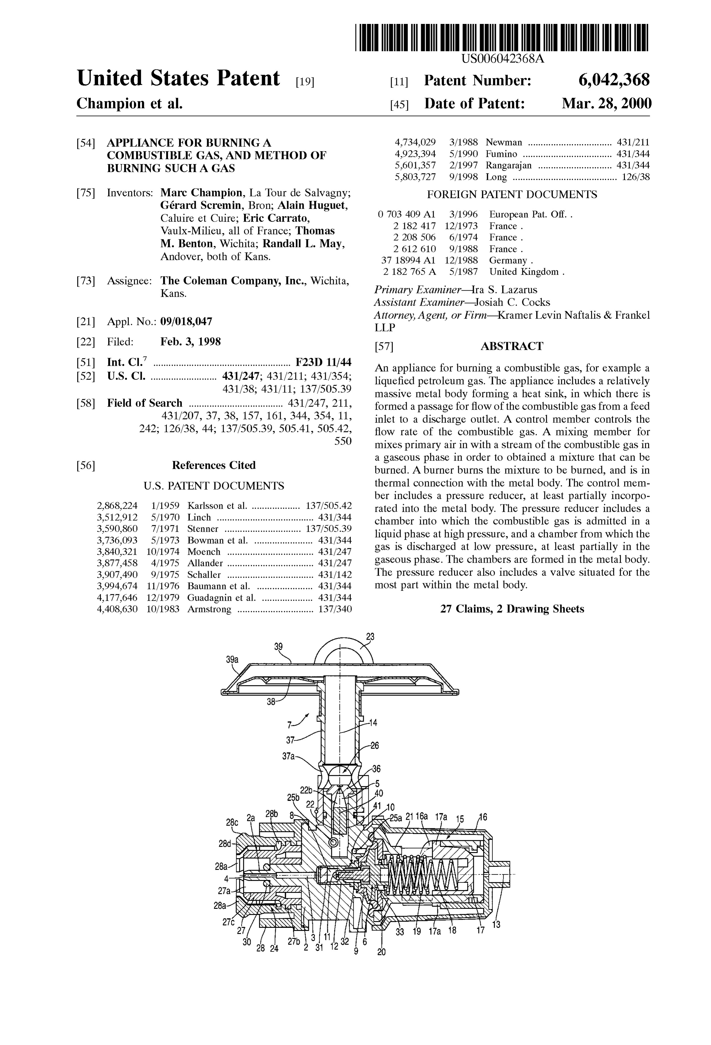
51) Int. Cl.' ...................................................... F23D 11/44 An appliance for burning a combustible gas, for example a 52) U.S. Cl. .......................... 431/247; 431/211; 431/354; liquefied petroleum gaS. The appliance includes a relatively 431/38; 431/11; 137/505.39 massive metal body forming a heat Sink, in which there is 58 Field of Search ..................................... 431/247, 211, formed a passage for flow of the combustible gas from a feed 431/207, 37, 38, 157, 161, 344, 354, 11, inlet to a discharge outlet. A control member controls the 242; 126/38, 44; 137/505.39, 505.41, 505.42, flow rate of the combustible gas. A mixing member for 550 mixes primary air in with a stream of the combustible gas in a gaseous phase in order to obtained a mixture that can be 56) References Cited burned. A burner burns the mixture to be burned, and is in
ber includes a pressure reducer, at least partially incorpo 2,868,224 1/1959 Karlsson et al. ................... 137/505.42 rated into the metal body. The preSSure reducer includes a 3,512,912 5/1970 Linch ...................................... 431/344 chamber into which the combustible gas is admitted in a 3.590,860 7/1971 Stenner ............ 137/505.39 liquid phase at high preSSure, and a chamber from which the 3,736,093 5/1973 Bowman et al. ... 431/344 -0 s 3,840,321 10/1974 Moench ........... ... 431/247 gas is discharged at low pressure, at least partially in the 3,877,458 4/1975 Allander ... ... 431/247 gaseous phase. The chambers are formed in the metal body. 3,907,490 9/1975 Schaller ............... ... 431/142 The pressure reducer also includes a valve situated for the 3,994,674 11/1976 Baumann et al. ... ... 431/344 most part within the metal body.
4,177,646 12/1979 Guadagnin et al. . ... 431/344 4,408,630 10/1983 Armstrong .............................. 137/340 27 Claims, 2 Drawing Sheets
till
Sys; 3NNW
3.NNNSAS YNS. WWWAN
SNN S. a NS Y 7 8
Page 2
Drawing sheet — no readable text.
Page 3
Drawing sheet — no readable text.
Page 4
APPLIANCE FOR BURNING A ization can be improved by providing and arranging a COMBUSTIBLE GAS, AND METHOD OF Vaporization loop, connected to the combustible gas flow BURNING SUCH A GAS passage and arranged on and outside the metal body, extend ing close to the burner and in a heat eXchange relationship
BACKGROUND OF THE INVENTION therewith.
The present invention relates to a burning appliance for An arrangement of this kind can Substantially improve burning a combustible gas, in applications including Stoves, Vaporization only during operation, but not when the appli heating appliances, lighting appliances, Welding appliances, ance is being Started or lit.
etc. SUMMARY OF THE INVENTION The term “burning appliance, appliance for burning and appliance' is intended to cover various appliances, which liquid For an appliance Supplied with combustible gas in the have the common characteristic of using the burning of a makes phase, the present invention is an arrangement that it possible to improve the degree of vaporization of combustible gas to generate heat, but which can in other the combustible respects be differentiated in terms of their applications 15 the appliance. gas, particularly when Starting or lighting including Stoves, heating appliances, lighting appliances,
Welding appliances, etc. In accordance with one aspect of the invention, to this end, the control member includes a preSSure reducer, at least
DESCRIPTION OF THE RELATED ART partially incorporated into the metal body and comprising a The ASSignee hereof manufactures and Sells under the chamber into which the combustible gas is admitted in the liquid phase at high pressure, and a chamber from which trade marks of MAX XTREMETM, XPEDITIONTM and Said gas is discharged at low pressure, at least partially in the XPERTTM a line of portable stoves for camping and hiking. gaseous phase, these chambers being formed in the metal The burners on such stoves are supplied with the combus body, together with a valve situated for the most part within tible gas in the liquid phase from a fuel can under pressure. the metal body.
The liquid fuel changes phase to the gaseous phase within 25 Using a Suitable experimental procedure, and for a flow the Stove and burns the in the gaseous phase.
Appliances of this kind in general comprise: rate of combustible gas (60/40% a butane/propane mixture) of the order of 240 g/h, at -5°C., it was demonstrated in an (i) a relatively massive metal body forming a heat sink, in appliance according to the present invention, and with all which there is formed a passage for the flow of the other aspects unchanged, the phenomenon of flaring, combustible gas from an inlet to which it is fed under explained earlier, is avoided, or in any case limited to an preSSure, to an outlet from which it is discharged in the acceptable level.
gaseous phase; In accordance With another aspect of the invention, two (ii) a member forming also a heat Sink, namely a tap, for unexpected advantages, which have been confirmed controlling the flow rate of the combustible gas, pref 35 experimentally, are also provided.
erably in liquid phase, flowing down the aforemen Firstly, another phenomenon known as fogging, which tioned flow passage; this control member is Separate arises out of the burning of a combustible gas, which is from and connected to the metal body by a flexible Supplied in the liquid phase, is reduced. Under Some pipe, circumstances, when the pressure of the combustible gas in (iii) a member for mixing primary air in which a stream 40 the liquid phase increases Substantially, the gas may be of the combustible gas in the gaseous phase, obtained discharged from the burner in an atomized form, that is to at the outlet for discharging in the gaseous phase, in Say in the form of a Suspension of droplets in a gaseous order to obtain a mixture that can be burned; and phase. This is the phenomenon known as fogging, which can (iv) a burner for burning the mixture to be burned, Significantly disrupt the operation of the burner. thermally connected with the metal body. 45
In accordance with one aspect of the invention, the
The expression “relatively massive” means that the mass aforementioned phenomenon practically disappears or in of the metal body is greater than that strictly needed from any case is confined within acceptable limits. which to hollow out the combustible gas flow passage. In accordance with another aspect of the invention, a The expression “heat sink” means the property whereby relatively stable or constant operation is achieved, when the the metal body can Store up heat, on account of its mass, 50 flow rate of combustible gas is relatively low, and when the especially by heat eXchange with its Surroundings. heat transferred from the burner to the metal body remains The term “in thermal connection with means any limited.
arrangement whereby the burner can exchange heat with the metal body, mainly by conduction and/or radiation; an preSSure In accordance with yet another aspect of the invention, the arrangement of this kind may include mounting the burner 55 reducer comprises a valve of the upstream type, that directly to the metal body. is to Say a shutter situated in the inlet chamber and returned Although the aforementioned appliances are quite toward a Seat.
Satisfactory, their performance at the time of lighting could According to this arrangement, operation is improved for be improved, at low temperatures, for example down to -5 tWO reasons:
C., and/or when using a combustible gas which contains a 60 (i) any increase in pressure in the inlet results in a relatively significant fraction of light hydrocarbons, for corresponding relative reduction in the reduced pres example a 60/40% butane/propane mixture. Such conditions Sure in the discharge chamber, and this makes the often lead to incomplete vaporization of the combustible appliance Self regulating; and gas, which can affect the performance of Said appliances and (ii) any overpressure of the combustible gas in the liquid result in flaring. 65 phase causes the valve of the pressure reducer to close, For this type of appliance it has been proposed, in and therefore closes the pressure reducer; in particular, accordance with document EP-A-0 703 409, that the vapor the pressure reducer is designed So that the overpres

Page 5
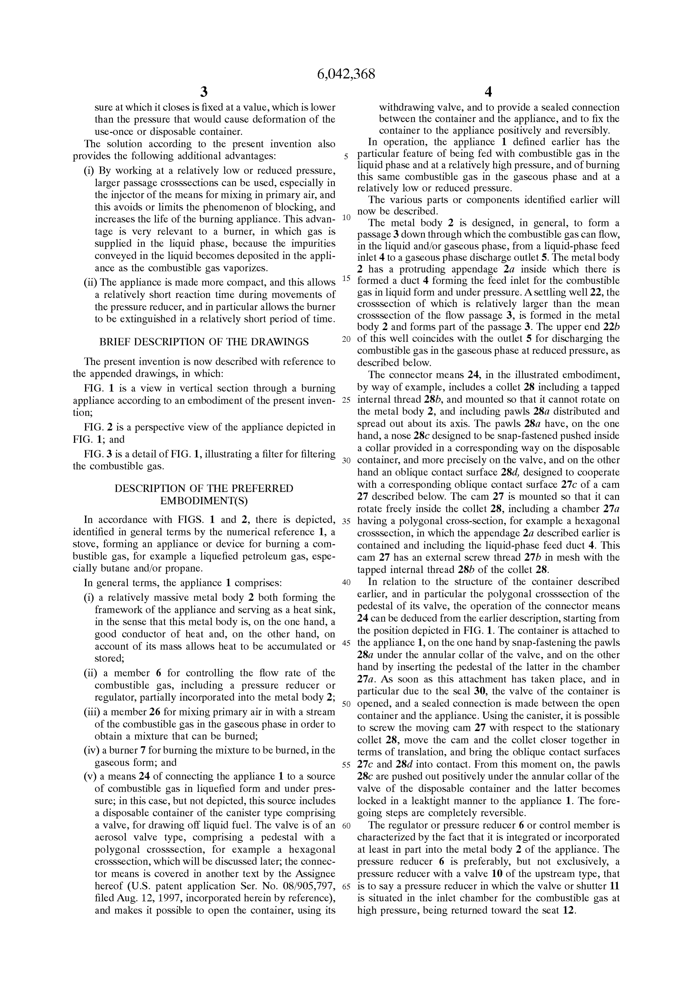
Sure at which it closes is fixed at a value, which is lower withdrawing valve, and to provide a Sealed connection than the pressure that would cause deformation of the between the container and the appliance, and to fix the use-once or disposable container. container to the appliance positively and reversibly. The Solution according to the present invention also In operation, the appliance 1 defined earlier has the provides the following additional advantages: 5 particular feature of being fed with combustible gas in the (i) By working at a relatively low or reduced pressure, liquid this phase and at a relatively high pressure, and of burning
Same combustible gas in the gaseous phase and at a larger passage croSSSections can be used, especially in relatively low or reduced pressure. the injector of the means for mixing in primary air, and The various parts or components identified earlier will this avoids or limits the phenomenon of blocking, and now be described.
increases the life of the burning appliance. This advan The metal body 2 is designed, in general, to form a tage is very relevant to a burner, in which gas is passage 3 down through which the combustible gas can flow, Supplied in the liquid phase, because the impurities in the liquid and/or gaseous phase, from a liquid-phase feed conveyed in the liquid becomes deposited in the appli inlet 4 to a gaseous phase discharge outlet 5. The metal body ance as the combustible gas vaporizes. 2 has a protruding appendage 2a inside which there is (ii) The appliance is made more compact, and this allows 15 formed a duct 4 forming the feed inlet for the combustible a relatively short reaction time during movements of gas in liquid form and under preSSure. A Settling well 22, the the pressure reducer, and in particular allows the burner croSSSection of which is relatively larger than the mean to be extinguished in a relatively short period of time. croSSSection of the flow passage 3, is formed in the metal body 2 and forms part of the passage 3. The upper end 22b
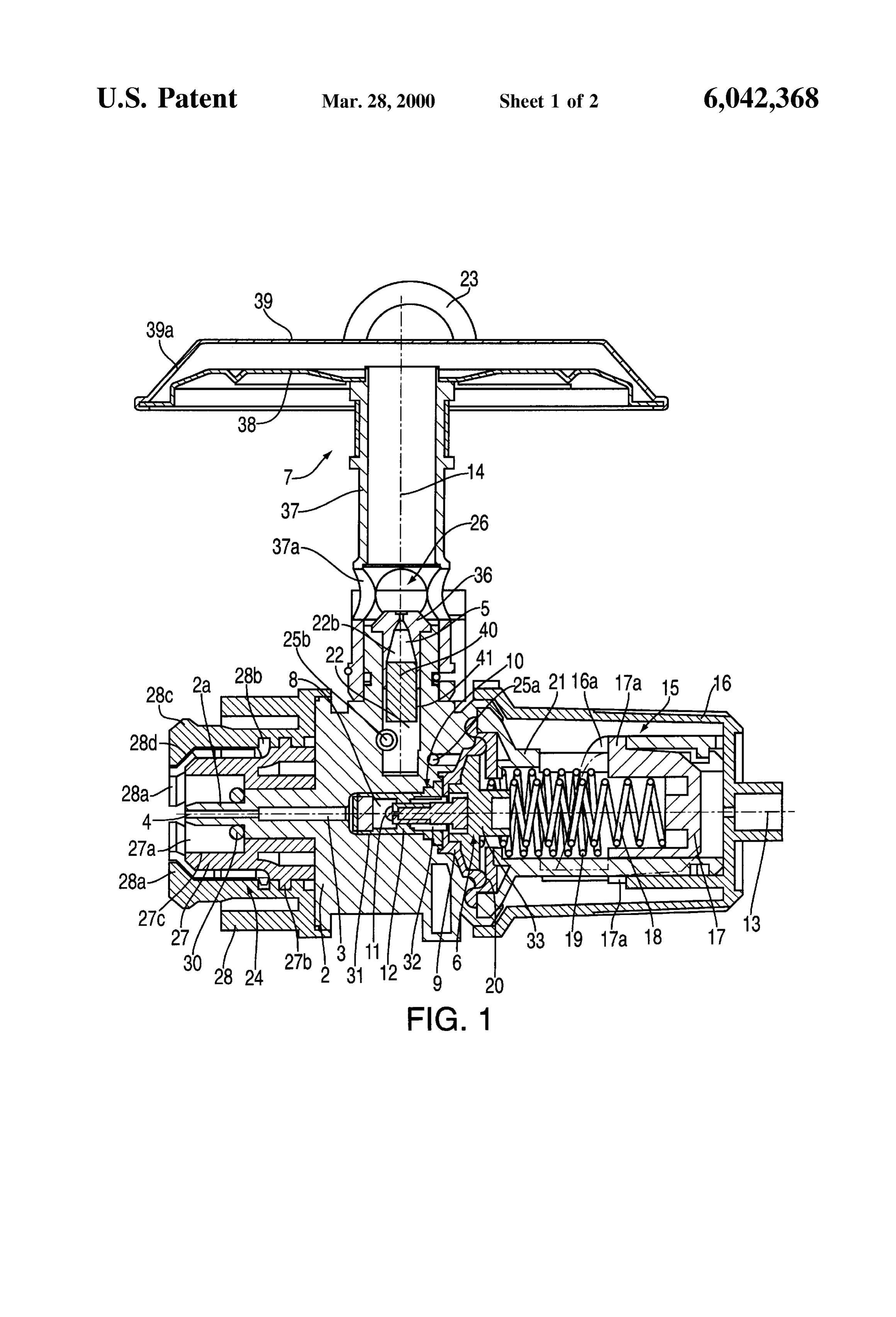
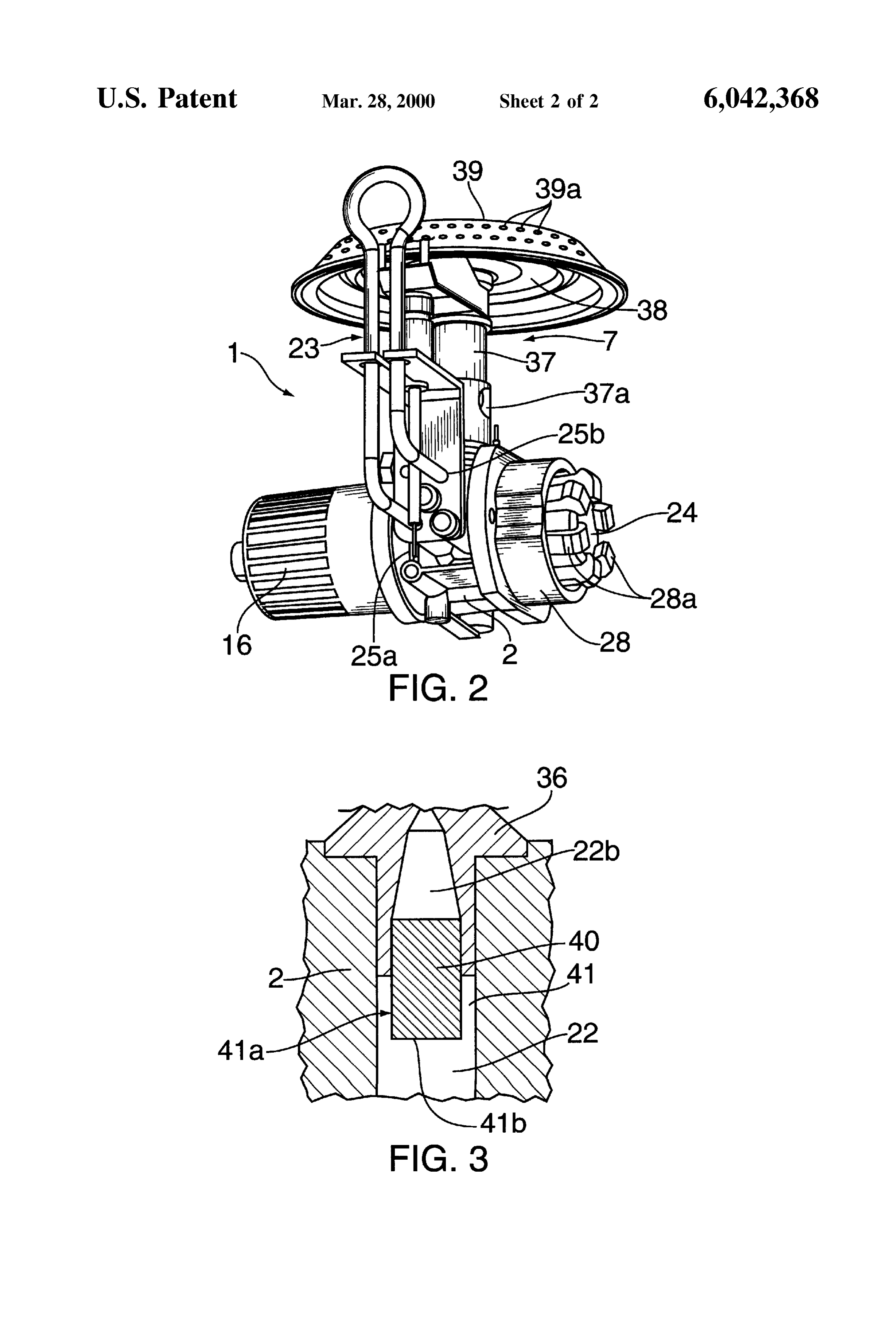
BRIEF DESCRIPTION OF THE DRAWINGS of this well coincides with the outlet 5 for discharging the combustible gas in the gaseous phase at reduced preSSure, as
The present invention is now described with reference to described below.
the appended drawings, in which: The connector means 24, in the illustrated embodiment, FIG. 1 is a view in vertical section through a burning by way of example, includes a collet 28 including a tapped appliance according to an embodiment of the present inven 25 internal thread 28b, and mounted So that it cannot rotate on tion; the metal body 2, and including pawls 28a distributed and FIG. 2 is a perspective view of the appliance depicted in Spread out about its axis. The pawls 28a have, on the one FIG. 1; and hand, a nose 28c designed to be Snap-fastened pushed inside a collar provided in a corresponding way on the disposable
FIG. 3 is a detail of FIG. 1, illustrating a filter for filtering container, the combustible gas. and more precisely on the valve, and on the other hand an oblique contact Surface 28d, designed to cooperate
DESCRIPTION OF THE PREFERRED with a corresponding oblique contact Surface 27c of a cam 27 described below. The cam 27 is mounted So that it can
EMBODIMENT(S) rotate freely inside the collet 28, including a chamber 27a In accordance with FIGS. 1 and 2, there is depicted, 35 having a polygonal cross-section, for example a hexagonal identified in general terms by the numerical reference 1, a croSSSection, in which the appendage 2a described earlier is Stove, forming an appliance or device for burning a com contained and including the liquid-phase feed duct 4. This bustible gas, for example a liquefied petroleum gas, espe cam 27 has an external Screw thread 27b in mesh with the cially butane and/or propane. tapped internal thread 28b of the collet 28. In general terms, the appliance 1 comprises: 40 In relation to the structure of the container described (i) a relatively massive metal body 2 both forming the earlier, and in particular the polygonal croSSSection of the framework of the appliance and Serving as a heat Sink, pedestal of its valve, the operation of the connector means in the Sense that this metal body is, on the one hand, a 24 can be deduced from the earlier description, Starting from good conductor of heat and, on the other hand, on 45 the position depicted in FIG.1. The container is attached to the appliance 1, on the one hand by Snap-fastening the pawls account of its mass allows heat to be accumulated or
Stored; 28a under the annular collar of the valve, and on the other (ii) a member 6 for controlling the flow rate of the hand by inserting the pedestal of the latter in the chamber combustible gas, including a pressure reducer or particular 27a. AS Soon as this attachment has taken place, and in regulator, partially incorporated into the metal body 2, 50 opened, andduea Sealed to the seal 30, the valve of the container is connection is made between the open (iii) a member 26 for mixing primary air in with a stream container and the appliance. Using the canister, it is possible of the combustible gas in the gaseous phase in order to to Screw the moving cam 27 with respect to the Stationary obtain a mixture that can be burned; collet 28, move the cam and the collet closer together in (iv) a burner 7 for burning the mixture to be burned, in the terms of translation, and bring the oblique contact Surfaces gaseous form; and 55 27c and 28d into contact. From this moment on, the pawls (v) a means 24 of connecting the appliance 1 to a Source 28c are pushed out positively under the annular collar of the of combustible gas in liquefied form and under pres Valve of the disposable container and the latter becomes Sure, in this case, but not depicted, this Source includes locked in a leaktight manner to the appliance 1. The fore a disposable container of the canister type comprising going Steps are completely reversible.
a valve, for drawing off liquid fuel. The valve is of an 60 The regulator or pressure reducer 6 or control member is aerosol valve type, comprising a pedestal with a characterized by the fact that it is integrated or incorporated polygonal croSSSection, for example a hexagonal at least in part into the metal body 2 of the appliance. The croSSSection, which will be discussed later, the connec preSSure reducer 6 is preferably, but not exclusively, a tor means is covered in another text by the ASSignee preSSure reducer with a valve 10 of the upstream type, that hereof (U.S. patent application Ser. No. 08/905,797, 65 is to Say a pressure reducer in which the valve or Shutter 11 filed Aug. 12, 1997, incorporated herein by reference), is situated in the inlet chamber for the combustible gas at and makes it possible to open the container, using its high pressure, being returned toward the Seat 12.
Page 6
S 6
In accordance with the embodiment shown in FIG. 1, the 26 for letting in primary air, in the direction in which the control member 6 comprises: combustible gas flows. This filter is more particularly push (i) a body 31 inserted in the metal body 2, determining the fitted into a hole formed in the injector 36, facing the well aforementioned Seat 12, 22. The filter 40 and the well 22 are arranged one with (ii) a chamber 8 into which the combustible gas is respect to the other in Such a way as to form a peripheral gap admitted in the liquid phase at high preSSure, deter 41 between the wall of the well and a lateral part 4.0a of the mined both in the body 31, and therefore in the metal filter, so that the filter 40 is arranged like a suction strainer. body 2: AS a preference, the filter consists of a cylinder or plug of a (iii) a chamber 9 from which the combustible gas is Sintered and therefore porous material (especially a metal). discharged at low pressure, at least partially in the By varying the height of the filter 40 from the injector 36, gaseous phase, formed in the metal body 2, the size of the lateral area 4.0a of the filter and therefore the (iv) the valve 10 of the upstream type, which combines time that the filter takes to block can be altered, all other the Shutter 11 with its Seal, and the Seat 12 against things being equal. The upstream face 41b of the filter 40 is which Said shutter is returned by a Spring 32, situated Some distance from the lower end 22a of the well (v) a diaphragm 20, closing the discharge chamber, the 15 22, as close as possible to the injector 36. circular edge of which is clamped between the metal The member 26 for mixing in primary air combines, on body 2 and an outer bonnet 21 mounted on said body; the one hand, the injector 36 situated at the outlet 22b of the (vi) a cap 33, integral with or fixed to the diaphragm 20, well 22, and on the other hand, openings 37a made in the resting against the end of the shutter 11 at the opposite tube 37 of the burner 7. The jet of combustible gas emitted end to the seat 12; by the injector 36 therefore entrains through the orifices 37a (vii) a Spring 18, resting at one end against the cover 33, the primary air needed for combustion.
outside the discharge chamber 9, and at the other end The burner 7 comprises two pressed parts 38 and 39 against a slide 17, mounted freely and axially inside the crimped together, forming a gap between them in which the bonnet 21; and mixture to be burned can circulate, the part 39 having (viii) an operating member 15, situated outside the metal 25 perforations 39a.
body 2 and comprising at least two marked positions, A vaporization loop 23 outside the metal body 2 is preferably connected one in which the valve 10 is open and in which the tible gas, in the direction to the flow passage 3 for the combus preSSure of the combustible gas leaving the discharge in which this gas flows, between an chamber is controlled, and the other a closed position intermediate inlet 25a consisting of an orifice made in the in which the valve 10 is locked in the closed position; metal body 2, communicating with the discharge chamber 9, and an intermediate outlet 25b entering the well 22 some this operating member 15 combines, first of all the distance from its lower end 22a and approximately tangent bonnet 21 described earlier, mounted on the metal body to the circumference or cylindrical interior Surface of the 2; Secondly, the Slide 17 mounted So that it can move well 22.
freely in terms of translation within the bonnet 21, resting against the means or Spring 18 for returning the 35 These arrangements make it possible for heavy impurities diaphragm 20; thirdly a means or spring 19 for return liable to be deposited upon vaporization of the combustible ing the slide 17, away from the diaphragm 20 of the gas, particularly by the Swirling effect of the Stream of gas preSSure reducer, resting at one end against the bonnet in theonwell 22 to be held in the bottom of the well 22, which 21 and at the other end against the slide 17; and fourthly liesThe the axis 14 of the burner.
vaporization loop 23 is preferably designed to be a means for actuating the Slide 17 in terms of 40 translation, composed of a knob 16, mounted So that it removable inlet 25a from the metal body 2, and in particular from the and outlet 25b, which allows the loop to be adapted can rotate freely coaxially on the bonnet 21 and com to Suit the various configurations or arrangements of the prising two Symmetric ramps 16a in rotation with burner 7, depending respect to the axis 13 and in contact respectively with appliance, without having on the application or intended use of the two opposed studs 17a of the slide 17. 45 to change the rest of Said appli
Various positions of adjustment may be formed on the This vaporization loop 23 plays a part in conducting the Symmetric ramps 16a between the two marked, open and closed, positions of the operating member 15. residual heat emitted by the burner 7 away to the metal body As clearly shown in FIG. 1, the inlet chamber 8 of the 2. Because of what has been described earlier, and in illustrated embodiment is immediately adjacent to the liquid 50 operation, from being drawn off in the liquid phase and at phase inlet 4, and this has the advantage of limiting the high pressure from a disposable container, it will be appre amount of combustible gas that remains in the appliance and is vented to atmosphere when a disposable container is ciated by those skilled in the art that the flow of combustible disconnected from Said appliance as described earlier. gas in the illustrated embodiment is as follows: Furthermore, this chamber 8 is preferably immediately adja 55 (i) Entry in the liquid phase and at high pressure into the cent to the axis 14 of the burner, which places it, at least inlet chamber 8, possibly after filtration; the high partially, in the region for heat transfer from the burner 7. preSSure is, for example, 1 to 9 bar; Further, the feed duct 4 is preferably aligned along an axis (ii) Controlled pressure reduction in the liquid phase 13 with an axis of the pressure reducer 6, and more precisely across the valve 10, and passage of the combustible gas with an axis of the valve 11. The axis 13 is itself preferably 60 at low pressure into the discharge chamber 9, at least orthogonal or perpendicular to the axis 14 of the well 22 partially in the gaseous phase; described earlier, which also corresponds to that of the outlet (iii) Entry and circulation of the combustible gas into and 5, through which the combustible gas is discharged in the in the vaporization loop 23 and return of the combus gaseous form, of the injector 36, and of the burner 7 tible gas, entirely in the gaseous phase, to the well 22, described below. 65 (iv) Passage of the combustible gas in the gaseous phase As shown more specifically in FIG. 3, a filter 40 can be and at low pressure through the upper end 22b of the placed in the well 22 immediately upstream of the member well 22, which communicates with the member 26 for
Page 7
mixing in primary air, namely the injector 36 from means for returning Said Slide, away from Said diaphragm which a stream of the combustible gas is obtained; of Said pressure reducer, and (v) The mixture to be burned is obtained by mixing the means for actuating Said slide in translation, comprising Stream of combustible gas with primary air and Said (i) a knob mounted to rotate freely on the bonnet and mixture is burned in the burner 7. compressing a ramp and (ii) a stud extending from Said All the aforementioned provisions make it possible to slide and contacting Said ramp.
provide a significant improvement, as described earlier, to 5. The appliance according to claim 1, wherein Said metal the operation of a burner, which burns in the gaseous phase, body further includes a well formed therein which commu but is Supplied with combustible gas in the liquid phase. nicates at a lower end thereof with the pressure reducer While the present invention has been described with discharge chamber, and at an upper end thereof with the outlet.
respect to what is presently considered to be the preferred 6. The appliance according to claim 5, further comprising embodiments, it should be understood that the invention is a vaporization loop connected in flow communication to the not limited to the disclosed embodiments. To the contrary, flow passage intermediate the flow passage inlet and outlet, the invention is intended to cover various modifications and Said vaporization loop extending from an intermediate inlet equivalent arrangements, Some of which are discussed 15 to an intermediate outlet in the direction in which the above, included within the Spirit and Scope of the appended combustible gas passes, and extending in an axial direction claims. Therefore, the Scope of the following claims is of and close to the burner, So as to have a heat-exchange intended to be accorded the broadest reasonable interpreta relationship therewith.
tion So as to encompass all Such modifications and equiva 7. The appliance according to claim 6, wherein the lent Structures and functions. intermediate outlet enterS Said well Some distance from the What is claimed is: lower end of Said well.
1. An appliance for burning a combustible gas, compris 8. The appliance according to claim 6, wherein the ing: intermediate outlet enterS Said well at a tangent to a circum a relatively massive metal body forming a heat Sink, in 25 ference thereof.
which there is formed a passage for a flow of the 9. The appliance according to claim 6, wherein Said combustible gas, Said flow passage including an inlet to Vaporization loop is removably attached to Said metal body. which the combustible gas is fed in a liquid phase, and 10. The appliance according to claim 5, further compris an outlet, from which the combustible gas is discharged ing a filter in Said well immediately upstream of the member in a gaseous phase; for mixing in primary air, in the direction in which the a control member for controlling a flow rate of the combustible gas flows.
combustible gas flowing down Said flow passage; 11. The appliance according to claim 10, wherein Said a mixing member for mixing primary air in with a stream filter and said well are situated one with respect to the other of the combustible gas in the gaseous phase, discharged in Such a way as to form a peripheral gap between an interior from the outlet, in order to obtain a mixture that can be 35 wall of said well and part of a lateral surface of said filter. 12. The appliance according to claim 10, wherein an burned; and wherein, Said control member comprises a pressure upstream face of Said filter is situated Some distance from the lower end of Said well.
reducer, at least partially incorporated into Said metal 13. The appliance according to claim 1, wherein the inlet body and comprising an inlet chamber into which the chamber is adjacent to an axis of Said burner. combustible gas is admitted in the liquid phase at high 40 14. A method preSSure, a discharge chamber from which Said gas is the Steps of: for burning a combustible gas comprising discharged at low pressure, at least partially in the gaseous phase, the inlet and discharge chambers being providing the combustible gas in a liquid phase under preSSure, formed in Said metal body, and a valve disposed between the inlet and discharge chambers, Situated 45 drawing off Said gas in the liquid phase; mainly within Said metal body, and Vaporizing the drawn gas in order to obtain a Stream of the wherein the inlet chamber is immediately adjacent to the combustible gas in a gaseous phase, inlet of the flow passage. mixing the Stream of combustible gas with primary air in 2. The appliance according to claim 1, wherein Said valve order to obtain a mixture that can be burned; is of an upstream type, comprising a shutter Situated in the 50 burning the mixture; and inlet chamber and returnable toward a Seat. venting any combustible gas in a liquid phase that may 3. The appliance according to claim 1, wherein the remain, preSSure reducer further comprises an operating member for wherein the vaporization Step includes Subjecting the operating on Said valve, Situated outside Said metal body and combustible gas to a pressure reduction in order to movable between at least two positions, one an open posi 55 obtain Said combustible gas at least partially in the tion in which Said valve is open and in which the preSSure gaseous phase at relatively low pressure, from which of the combustible gas leaving the discharge chamber is the Stream of combustible gas is obtained for mixing controlled, and another a closed position in which Said valve with the primary air.
is locked closed. 15. An appliance for burning a combustible gas, compris 4. The appliance according to claim 3, wherein the 60 ing:
preSSure reducer further comprises a diaphragm, closing the a metal body that is relatively massive So as to Serve as a discharge chamber, and means for returning Said diaphragm, heat Sink, and in which there is formed an inlet chamber and Said operating member comprises: into which the combustible gas is admitted in a liquid a bonnet, mounted on Said metal body; phase at high pressure, a discharge chamber down a slide mounted to move freely in terms of translation 65 Stream of the inlet chamber, and an outlet downstream within the bonnet, resting against the means for return of the discharge chamber and from which a stream of ing Said diaphragm of Said pressure reducer, the combustible gas is discharged in a gaseous phase;
Page 8
a valve, through which the combustible gas flows from the prising a ramp and (ii) a Stud extending from the slide inlet chamber to the discharge chamber, Situated Sub and contacting the ramp.
Stantially within the metal body, for regulating a flow 19. The appliance according to claim 15, wherein the rate of the combustible gas So that the combustible gas metal body further includes a well formed therein having a in the discharge chamber is at low pressure and at least lower end, in flow communication with the discharge partially in the gaseous phase; chamber, and an upper end, in flow communication with the outlet.
a mixing member for mixing primary air with the Stream 20. The appliance according to claim 19, further com of the combustible gas discharged from the outlet, in prising a filter in the well upstream of the outlet. order to obtain a mixture to be burned; and 21. The appliance according to claim 20, wherein the filter a burner for burning the mixture to be burned, the burner and the well are juxtaposed So as to define a peripheral gap being thermally connected with the metal body, between an interior wall of the well and a lateral Surface of wherein the metal body includes an inlet to which the the filter.
combustible gas is fed in the liquid phase and wherein 22. The appliance according to claim 20, wherein and the inlet chamber is immediately adjacent to the inlet. 15 upstream face of the filter is spaced from the lower end of 16. The appliance according to claim 15, wherein the the well.
Valve is an upstream type, comprising a shutter, situated in 23. The appliance according to claim 15, further com the inlet chamber, and a Seat, toward which the Shutter is prising a vaporization loop intermediate of and in flow returnable. communication with the discharge chamber and the outlet, 17. The appliance according to claim 15, further com the vaporization loop extending from the metal body and prising an operating member for operating on the valve, the passing close to the burner, So as to have a heat-exchange operating member being situated outside the metal body and relationship therewith.
movable between at least an open position, in which the 24. The appliance according to claim 23, wherein the valve is open and in which the pressure of the combustible metal body further includes a well formed therein, the gas leaving the discharge chamber is controlled, and a closed 25 Vaporization loop emptying into the well at a distance from position, in which the valve is locked closed. a lower end of the well, and the well having an upper end in 18. The appliance according to claim 17, further com flow communication with the outlet.
prising a diaphragm, closing the discharge chamber, and 25. The appliance according to claim 23, wherein the means for returning the diaphragm, and wherein the oper metal body further includes a well formed therein, the ating member comprises: Vaporization loop emptying into the well Substantially at a a bonnet, mounted on the metal body; tangent to an interior wall of the well, and the well having a slide, mounted to translate within the bonnet, and resting an26. upper end in flow communication with the outlet. The appliance according to claim 23, wherein the against the means for returning Said diaphragm; vaporization loop is removably attached to the metal body. means for returning the Side, away from the diaphragm; 27. The appliance according to claim 15, wherein the inlet
chamber is adjacent to an axis of the burner.
means for actuating translation of the Slide, comprising (i) an actuator mounted to rotate on the bonnet and com k k k k k
Provenance
- Collection
- Cited prior art
- Original PDF
- patentimages.storage.googleapis.com →
- Filed
- 1998-02-03
- Pages
- 8
- Method
- pdftotext (the PDF's own text layer) + pdftoppm 300dpi page scans
- Source
- Google Patents bibliographic record
- Granted
- 2000-03-28
- Inventors
- Marc Champion; Gerard Scremin; Alain Huguet; Eric Carrato; Thomas M. Benton; Randall L. May; Coleman Co Inc
- Transcribed from
- patentimages.storage.googleapis.com →