patent · US5123397
Vehicle management computer
23 June 1992
Page 1 — bibliographic record
United States Patent (19) 11 Patent Number: 5,123,397 Richeson (45) Date of Patent: Jun. 23, 1992 (54) VEHICLE MANAGEMENT COMPUTER ated in a plurality of different operating modes is dis (75) Inventor: William E. Richeson, Fort Wayne, closed. Different operating modes are available during Ind. normal operation. Under high demand conditions, the engine may be run as a conventional inefficient but 73) Assignee: North American Philips Corporation, effective throttled engine or converted to operation in a New York, N.Y. fourth mode as a two-stroke cycle engine. The vehicle 21 Appl. No.: 521,500 management system includes a first read only memory for storing a fixed table of engine operating parameters (22 Filed: May 10, 1990 corresponding to various engine conditions, and A method of and apparatus for starting and accelerating a
Related U.S. Application Data vehicle through a range of vehicle speeds during which 62) Division of Ser. No. 226,418, Jul. 29, 1988, Pat. No. the vehicle internal combustion engine is operated in a 4,945,870. plurality of different operating modes is disclosed. Dif 51 Int. Cl........................ FO2M 25/07; FO1L 25/08 ferent operating modes are available during normal 52 U.S.C. .................................... 123/568; 123/443; operation. Under high demand conditions, the engine 123/316; 123/571; 123/90.16 may be run as a conventional inefficient but effective 58) Field of Search ............... 123/90.11, 90.15, 90.16, throttled engine or converted to operation in a fourth 123/568, 569, 571, 316, 443 mode as a two-stroke cycle engine. The vehicle man (56) References Cited agement system includes a first read only memory for storing a fixed table of engine operating parameters
2,820,339 1/1958 Grieshaber et al. ................ 123/316 dom access second storage means for storing a table of 2.931,347 4/1960 Williams .............. ... 123/90.16 engine operating parameters corresponding to various 2.997,991 8/1961 Roan ................................ 123/90.6 engine conditions with the second table being initially 3,166,057 1/1965 Konrad et al.... ... 23/568 X the same as the first table. The system responds to 3,548,798 12/1970 Fleischer et al. 123/179A X sensed engine conditions to modify the parameters in 3,844,528 10/1974 Massie .............................. 251/30.02 the second table and controls the vehicle in accordance 4,357,917 11/1982 Aoyama .............. . . 123/90.6 4,700,684 10/1987 Pischinger et al. . 123/90.11 with the parameters stored in the second table. Both 4,722,315 2/1988 Pickel .................. ... 123/90.1 short term modification to accommodate dynamic 4,844,022 7/1989 Konno. ... 123/90.16 changes in the sensed engine conditions and long term 4,875,455 10/1989 Hashimoto et al. . ... 123/568 modification to compensate for relatively slow changes 4,926,823 5/1990 Kishi et al. ....................... 123/90.16 in the engine and the management system are made to Primary Examiner-Willis R. Wolfe the information in the random access memory. The 57) ABSTRACT modifications may be on an overall engine basis or an individual cylinder basis.
A method of and apparatus for starting and accelerating a vehicle through a range of vehicle speeds during which the vehicle internal combustion engine is oper 2 Claims, 4 Drawing Sheets
Page 2
ON/OFF SWITCH VEHICLE VELOCITY 3
OPERATOR START
AND His ERAESAC TRANSMISSION STATUS
OPUS OP2RAN
GOALS FUEoctances 97 is STOICHIOMETRY
OPERATOR
VEHICLE
ENMRONMEN
M MGALLON
ENGINE RPM
DISPLAY VEHICLE VEOCTY
OOANT TEMPERATUR
MODUS OPERAND
AIR MA FLOW 4 RANK AN
KNOCK SENSOR 89
VEHICLE - CYNDER PRESSURE
INTAKE MANFOLD PRESSURE53 ENGINE ENGINE RPM 6- 5g FUEL TEMPERATURE ENGINE ORQUE3 OOLANT TEMPERATUR 33 ExHAUSEMPERATURE BAROMETRIC PRESSURE 49 EXHAUST OXYGEN39
IGNITION CONTROL 37
FUE CONTROL 93
PROCESSOR AIR CONTROL 95
VALUE CONTROL 9
SUPERCHARGER 92
Page 3
START/STOP 2. CLOCK -35 SNE MODUS OPERAND 7 T CPU
25 DRIVER
USE START
PO P RAM 27
SSR
DRIVER
TRANSMISSION STATUS 97 T 75
CRANK SHAFT ANGLE ROM 29 NGINE TOP DEAD CENTER 33 WE
DRIVE
ENGINE RPM 6 OUTPUT
PEAK PRESSURE 43 23 DISPLAY PEAK PRESSURE TIME 77 TEST 8 5 BURN TIME 79 SEP-3' ENGINE TORGUE 73 O
AR MASS FOW 45 EXTERNAL MANFOLD PRESSURE 53 N. ACCESS
ACCELERATOR PEDAL 4
BRAKE PEDAL 67
VEHICLE OCTY 57
COOLANT TEMPERATURE-63
FUE OCTANE, STOCHOMETRY
BAROMETRIC PREssURE 49,69
EXHAUST TEMPERATURE S.
AIR HUMIDITY 5
Page 4
IGNITION
START - DRIVER
STOP
1952EAD-NL CRANK ANGLE
CRANK
ANGE
Erce
Y TOP tead centernication
DEAD CENTER INDICATION SHIFT OF ENING ASE
DRIVER
CHANGE T
COMMAND
CSSNS
DRIVER
EXHAUST
ESAY
OPENING
A Air VER
COMMAND
99 NRAM EXHAU
DETA
lo-NRAM ES5
STATE
FDRIVER
TEST a
SETUP
Page 5
COOLANT TEMPERATURE 63
AIR TEMPERATURE 47
STROBED
BAROMETRIC PRESSURE 49
AiR HUMIDITY 5 ANAOG cru
FUEL TEMPERATURE 55
Fuel octane a stochroMETRYrsg. "
MANFOLD PRESSURE 53 DIGITA ROM N-5
AUXLARY POWER REQUIREMENTS
TRANSMISSION STATUS r97 CONVERTER RAM - 27 RAM
OTHER INPUT 35 DELTA ACCELERATOR PEDAL 4 RAM NIO BRAKE PEDAL 67 COMMAND RAM VEHICLE VELOCITY 57 STEADY STATE
PM BMEP OR
SELECTED INPUTS
SELECTED INPUTS ANALOG TO
DIGITAL
CONVERTER
ISTEADY
STATE --O5
Page 6
that history. Because of these facts, the volumetric effi
VEHICLE MANAGEMENT COMPUTER ciency is peaked in a narrow region of the required engine operating envelope. The result is that the fixed
This is a divisional application of application Ser. No. can engines suffer when starting due to poor volumet 07/226,418, filed Jul. 29, 1988, now U.S. Pat. No. 5 ric efficiency, do not idle smoothly at fuel conserving 4,945,870. low engine speeds due to the intake valve closing some what after bottom dead center, do not idle without
SUMMARY OF THE INVENTION enriched combustion mixtures because of the reverse The present invention relates generally to computer flow of exhaust to the intake manifold due to intake management of the overall operation of a vehicle and 10 exhaust valve overlap, do not idlewell enough to allow more particularly to a system for controlling the operat using less than the full complement of cylinders, and ing parameters of the vehicle's spark ignited internal provide less torque than is possible throughout most of combustion engine and in compression ignition engines the engine's operation range due in a large measure to including ignition timing, fuel, air intake, and intake and improper valve timing. The engines run best at the exhaust valve opening and closing, all interdependently 15 unique point where the cam gives its best volumetric controlled to achieve optimum overall vehicle perfor efficiency using mass flow effects that are less than what 2C. is possible due to the throttling effects of slowly open Internal combustion engine valves are almost univer ing and closing valves and hence the mass flow effects sally of a poppet type which are spring loaded toward a are, in themselves, largely uncontrolled. Additionally, valve-closed position and opened against that spring 20 at the high RPM range, these engines suffer from re bias by a cam on a rotating camshaft with the can shaft duced performance and valve gearjeopardy due to high being synchronized with the engine crankshaft to valve seating velocities and approaching valve float. achieve opening and closing at fixed preferred times in Because of the fact that the valve opening and closing the engine cycle. This fixed timing is a compromise rates vary directly with engine RPM, the valve gear between the valve timing best suited for high engine 25 springs operate in a region where they put the safe long speed and the timing best suited to lower speeds or life operation of the system in jeopardy due to their engine idling speed. being in a transition between being a lumped parameter The prior art has recognized numerous advantages and a distributed parameter element.
which might be achieved by replacing such can actu In the present fixed cam operated valve engines, the ated valve arrangements with other types of valve 30 brake specific fuel consumption curve drops to a mini opening mechanism which could be controlled in their mum as the air to fuel ratio goes from the best power opening and closing as a function of engine speed as point through stoichiometric to the best efficiency well as engine crankshaft angular position or other point. It then starts rising and the engine performance engine parameters. For example, U.S. Pat. No. drops off and becomes unstable at the "lean burn limit." 4,009,695 discloses hydraulically actuated valves in turn 35 This rise and instability are primarily caused by the controlled by spool valves which are themselves con decreased burning rate, incomplete burning, and vari trolled by a dashboard computer which monitors a ability, and ultimately lack of, appropriate ignition for number of engine operating parameters. This patent flame propagation throughout the volume of interest. references many advantages which could be achieved The present cam operated valves require valve overlap by such independent valve control, but is not, due to its 40 in order to attain high volumetric efficiency. This valve relatively slow acting hydraulic nature, capable of overlap causes exhaust gas dilution of the charge at low achieving these advantages. The patented arrangement engine RPM. The dilution of the charge by exhaust gas attempts to control the valves on a real time basis so that transfer, in turn, reduces the lean burn limit the overall system is one with feedback and subject to The decreased over-all burning propensity of lean the associated oscillatory behavior. 45 burns causes the pressure versus crank shaft angle to In U.S. Pat. Nos. 4,736,724 and 4,730,594 a number of rise more slowly and, with the effects of required turbu engine performance indicators are monitored for the lence for less burning time, with greater variance, peak purpose of controlling the fuel-air mixture supplied to ing later and it may fall to such a low value during the the engine. In U.S. Pat. No. 4,730,590 a number of en expansion stroke that the burning may be quenched or, gine performance indicators are monitored and a look 50 if not quenched, vented to the exhaust while still burn up table is employed for the purpose of controlling the ing. These problems can be somewhat alleviated by fuel-air mixture supplied to the engine. In U.S. Pat. No. operating the engine at a lower RPM; however, at 4,732,126 a number of engine performance indicators lower RPM the turbulence of the combusting gasses is are monitored for the purpose of controlling the width lower causing a reduction in &he burning rate, hence, of a pulse supplied to fuel injectors thereby determining 55 lower RPM assists the situation only to a limited extent. the fuel-air mixture supplied to the engine. Another choice is to advance the ignition point thereby From the forgoing, it is apparent that fuel and igni moving the ignition and burning process back relative tion are relatively well managed on the present day to the crank angle. This also assists the situation; how automotive engine, however, the opening and closing of ever, advancing the ignition point causes the ignition the intake and exhaust valves are not. The design of 60 point to occur when the peak pressure, temperature and present conventional cam operated engine valves is the turbulence are less and less optimum for ignition to take result of an ensemble of trade-offs. The various ap place causing longer ignition delays with increased proaches of operating the valve gear with different probability of flame quenching taking place, in turn types of cam mechanisms, that allow some control of causing variable ignition timing, misfires and generally the valves, leave much to desire in engine performance 65 increased variance of the pressure as a function of time improvement because of the limited performance in the in the combustion chamber. These problems limit the area of controlling the valve position versus time his extent to which the brakespecific fuel consumption will tory and the resulting throttling of the valve port due to fall at higher air to fuel ratios. If these problems were
Page 7
solved, the brake specific fuel consumption and the vice generally similar in overall operation to the present emission would fall until the air to fuel ratio reached invention. One feature of this application is that control such high values that entropy would grow to such a valves and latching plates have been separated from the level where the thermal efficiency would become the primary working piston to provide both lower latching dominant limiting factor. 5 forces and reduced mass resulting in faster operating The ignition of the fuel-air charge can be effected by speeds.
controlling the turbulence, temperature and pressure at The presently copending applications Ser. No. the time of ignition along with an ignition source that 209,279 entitled PNEUMATIC ACTUATOR WITH can establish and maintain an ignition arc under these PERMANENT MAGNET CONTROL VALVE conditions. Highly turbulent conditions of the charge O LATCHING, now U.S. Pat. No. 4,852,528, and Ser. may blow out an ignition arc. When an induction igni No. 209,273 entitled PNEUMATIC ACTUATOR tion source is used, it must have sufficient potential to WITH SOLENOID OPERATED CONTROL break down the spark plug gap and sufficient energy to VALVES, now U.S. Pat. No. 4,873,948 both filed in the reestablish that breakdown potential if the arc is blown names of William E. Richeson and Frederick L. Erick out. The arc may need to be reestablished a number of son on Jun. 20, 1988 and assigned to the assignee of the times during the ignition period. As the gasses of the present invention address, among other things, im charge pass through the ignition gap, successful ignition provements in operating efficiency over the above of the overall charge takes place through the ignition of noted devices.
contiguous opportunities until there is a critical yield of Other related applications all assigned to the assignee combustion energy where massive propagation of the 20 of the present invention and filed in the name of William flame can be initiated. When these ignition source re E. Richeson on Feb. 8, 1988 are Ser. No. 07/153,262 quirements are met, the high turbulent charge can entitled POTENTIAL-MAGNETIC ENERGY greatly assist in increasing the probability of a success DRIVEN VALVE MECHANISM, now U.S. Pat. No. ful, fast and more complete charge burn. 4,883,025, where energy is stored from one valve mo Control of the volumetric charging, swirl, retained 25 tion to power the next, and Ser. No. 07/153,154 entitled heat, variable compression-expansion ratio, and appro REPULSION ACTUATED POTENTIAL EN.
priate control of ignition timing working in conjunction ERGY DRIVEN VALVE MECHANISM, now U.S. with the engine RPM and controlled fuel-air mixture Pat. No. 4,831,973 wherein a spring (or pneumatic and the cylinder pressure versus time pattern peaking equivalent) functions both as a damping device and as and shape can greatly extend the lean burn limit and the 30 an energy storage device ready to supply part of the usefulness of lean burn. As previously mentioned, in the accelerating force to aid the next transition from one present day cam operated valved engines, the fuel and position to the other.
ignition time are relatively well controlled; however, U.S. Pat. Nos. 4,109,630 and 4,373,486 assigned to the with all of the special advantages that the computer assignee of the present invention disclose improved and control of the engine valves makes possible, special 35 easily controlled breakerless ignition systems suitable improvements are needed in fuel-air and ignition man for utilization in conjunction with the present invention. agement to fully realize the overall synergistic effect. The entire disclosures of all of these copending applica In copending application Ser. No. 021,195 entitled tions and the aforementioned issued patents are specifi ELECTROMAGNETIC VALVE ACTUATOR, cally incorporated herein by reference. filed Mar. 3, 1987 in the name of William E. Richeson The availability of fast acting and easily controlled and assigned to the assignee of the present application, valve actuating mechanisms such as those disclosed in now U.S. Pat. No. 4,794,890, there is disclosed a valve the abovementioned copending applications makes pos actuator which has permanent magnet latching at the sible a more complete and efficient overall vehicle oper open and closed positions. Electromagnetic repulsion ation management than was heretofor possible. may be employed to cause the valve to move from one 45 Among the several objects of the present invention position to the other. Several damping and energy re may be noted the provision of an operator controlled covery schemes are also included. vehicle drive train which is effective to maximize the In copending application Ser. No. 07/153,257, enti operating economy of a vehicle using a spark ignited tled PNEUMATIC ELECTRONIC VALVE ACTU internal combustion engine, to maximize the perfor ATOR, filed Feb. 8, 1988 in the names of William E. 50 mance and the general transient and steady state vehicle Richeson and Frederick L. Erickson and assigned to the drivability, and to minimize harmful engine emissions assignee of the present application, now U.S. Pat. No. without the use of catalytic converters and to optimally 4,878,464, there is disclosed a somewhat similar valve affect economy and performance; the provision of a actuating device which employs a release type mecha more comprehensive computer control of vehicle oper nism rather than a repulsion scheme as in the previously 55 ating parameters: the provision of a vehicle manage identified copending application. The disclosed device ment system which takes full advantage of fast acting in this application is a truly pneumatically powered and highly controllable intake and exhaust valve mech valve with high pressure air supply and control valving anisms; the provision of a vehicle management com to use the air for both damping and as the primary mo puter which controls air-fuel, ignition and valving of an tive force. This copending application also discloses engine using a stored steady state table or map of engine different operating modes including delayed intake information, currently modifies that information ac valve closure and a six stroke cycle mode of operation. cording to dynamic vehicle behavior, and optimizes In copending application Ser. No. 07/153,155 filed that information on a long term basis in accordance Feb. 8, 1988 in the names of William E. Richeson and with average long term vehicle behavior; the provision Frederick L. Erickson, assigned to the assignee of the 65 of vehicle control which allows the vehicle engine to be present application and entitled PNEUMATICALLY operated in each of several different modes; the provi POWERED VALVE ACTUATOR, now U.S. Pat. sion of a vehicle management computer according to No. 4,899,700, there is disclosed a valve actuating de the previous object which may operate on an individual
Page 8
cylinder basis; and the provision of a vehicle control in The exemplifications set out herein illustrate a pre accordance with the previous object which includes ferred embodiment of the invention in one form thereof two-stroke cycle and six-stroke cycle modes. These as and such exemplifications are not to be construed as well as other objects and advantageous features of the limiting the scope of the disclosure or the scope of the present invention will be in part apparent and in part 5 invention in any manner.
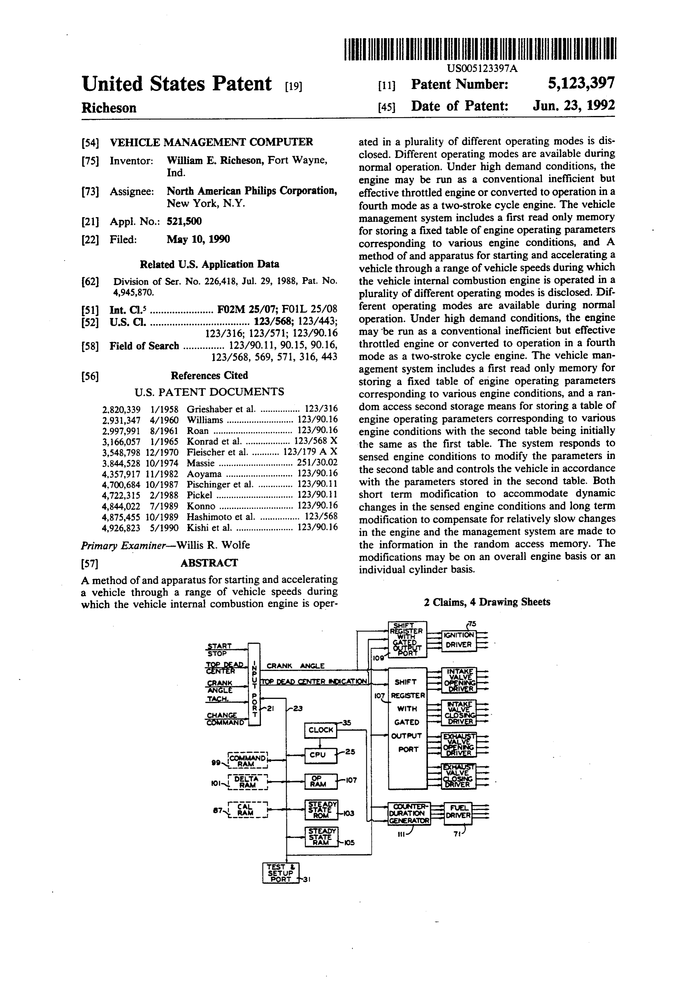
pointed out hereinafter. DESCRIPTION OF THE PREFERRED In general, a vehicle management system has an ar EMBOOMENT rangement for sensing a plurality of current vehicle performance indicators, environmental conditions, and Referring to the drawing generally, the vehicle man driver input, and a computing system which is respon 10 agement system is seen to sense a plurality of current sive to the sensed input information to determine a vehicle performance indicators and environmental con plurality of vehicle operating parameters. The comput ditions such as individual engine cylinder peak pressure ing system includes a microprocessor, and a read only 43, air mass flow 45 into the engine, ambient air temper memory including a look-up table of optimum engine ature 47, ambient air pressure 49, ambient air relative operating parameters under a wide variety of engine 5 humidity 51, engine intake manifold pressure 53, fuel performance conditions. Controls are actuated by the temperature 55, vehicle speed 57, exhaust gas tempera computing system for controlling the vehicle in accor ture 59, engine revolutions per minute 61, engine cool dance with the determined parameters. ant temperature 63, and engine crank shaft angle 65. Also in general and in one form of the invention, an Auxiliary power requirements such as air conditioner electronically controlled valve actuating mechanism 20 demand may be included as inputs. The system also and an associated intake valve on a reciprocating piston senses a number of driver inputs such as the degree 41 to four stroke cycle internal combustion engine are con which an accelerator pedal is depressed, the degree 67 trolled to operate selectively in a first mode at lower to which a brake pedal is depressed, the octane rating of engine speeds, a second mode at higher engine speeds, the particular fuel being used as well as its stoichiomet and a third mode at near maximum engine speeds. The 25 ric point or other indication of the energy content of the first mode includes increasing the portion of the cycle particular fuel 69, and a manual override 71 of the man during which the intake valve is open as the engine agement system. In response to this information, a plu speed increases, the second mode includes decreasing rality of vehicle performance determining operating the portion of the cycle during which the intake valve is parameters such as engine ignition timing 37, the dura open as the engine speed increases, and the third mode 30 tion and timing of opening and closing of engine intake includes opening and closing the intake valve in syn and exhaust valves 91, and the supply of fuel 93 and air chronism with engine speed to operate the engine as a 95 to the engine are controlled in accordance with the conventional throttled engine. The engine may also be environmental, performance and driver inputs. Fuel 93 operated in a two-stroke cycle mode under high de and air 95 are shown separately in FIG. 1 to emphasize mand conditions and a lean burn mode under low de 35 the fact that the present invention, while described in mand conditions conjunction with a conventional spark ignited internal Still further in general, the present invention allows combustion engine, is applicable to other engines such the conversion of at least one and perhaps all of the as Diesel engines. The supercharger control 92 may cylinders of the engine to a lean burn mode of operation enable an exhaust gas driven supercharger of enhanced only during periods of low engine demand. The lean low speed effectiveness as will be described later. A burn mode includes the steps of closing an exhaust valve microprocessor, and a read only memory including a of the converted cylinder before the piston of that cylin look-up table of optimum engine operating parameters der reaches a top dead center position to retain exhaust under a wide variety of engine performance conditions gas in that cylinder, and thereafter opening an intake are employed in the control process. valve of the converted cylinder to admit fuel and air to 45 Referring more particularly to FIG. 1, the heart of be mixed with the retained exhaust gas, and subse the vehicle management computer is the vehicle-engine quently compressed and ignited to obtain a power operational processor 11, itself shown in greater detail stroke from the piston of the converted cylinder. in FIG. 2. The processor 11 receives environmental
BRIEF DESCRIPTION OF THE DRAWING
conditions, such as barometric pressure 49; vehicle per 50 formance indicators, such as vehicle velocity 57; opera
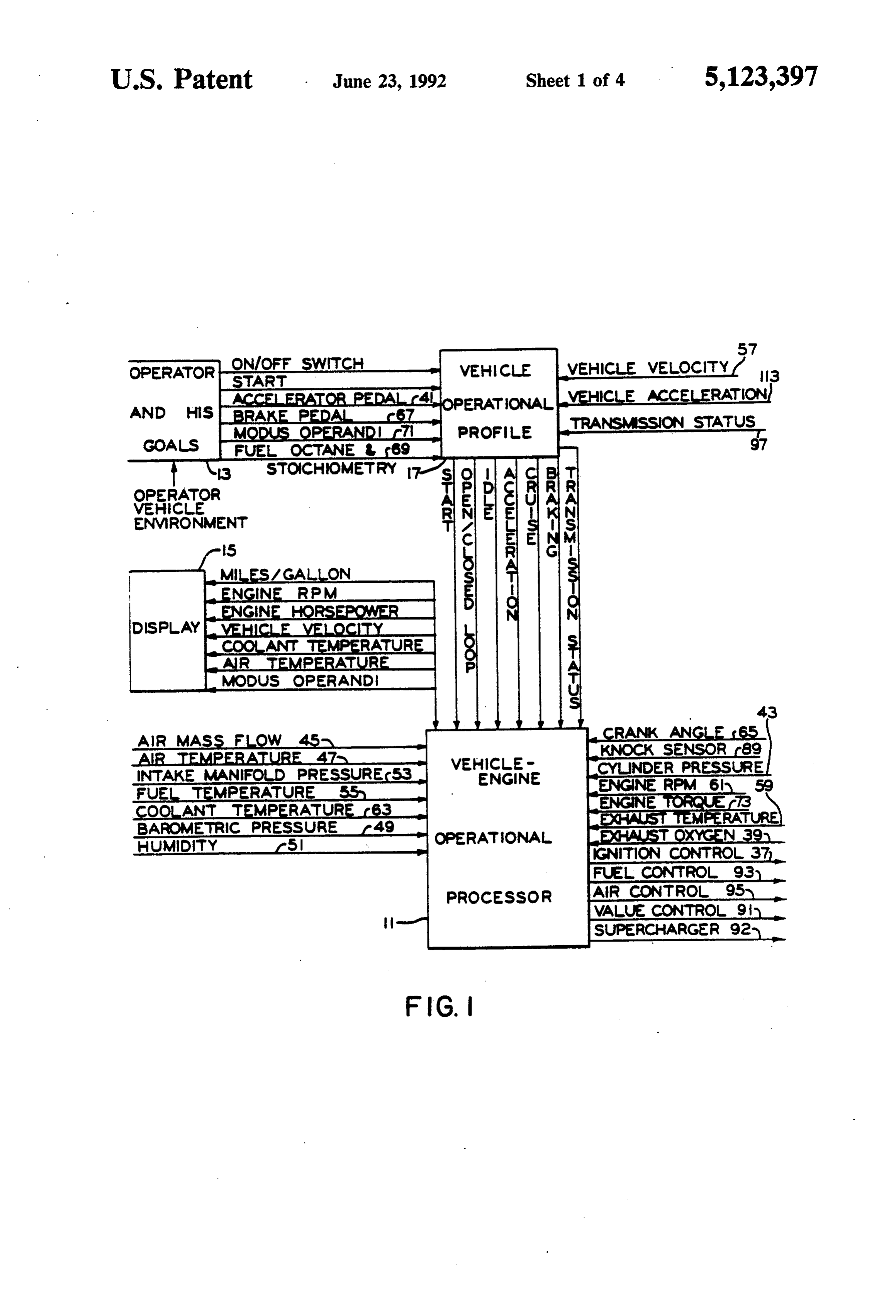
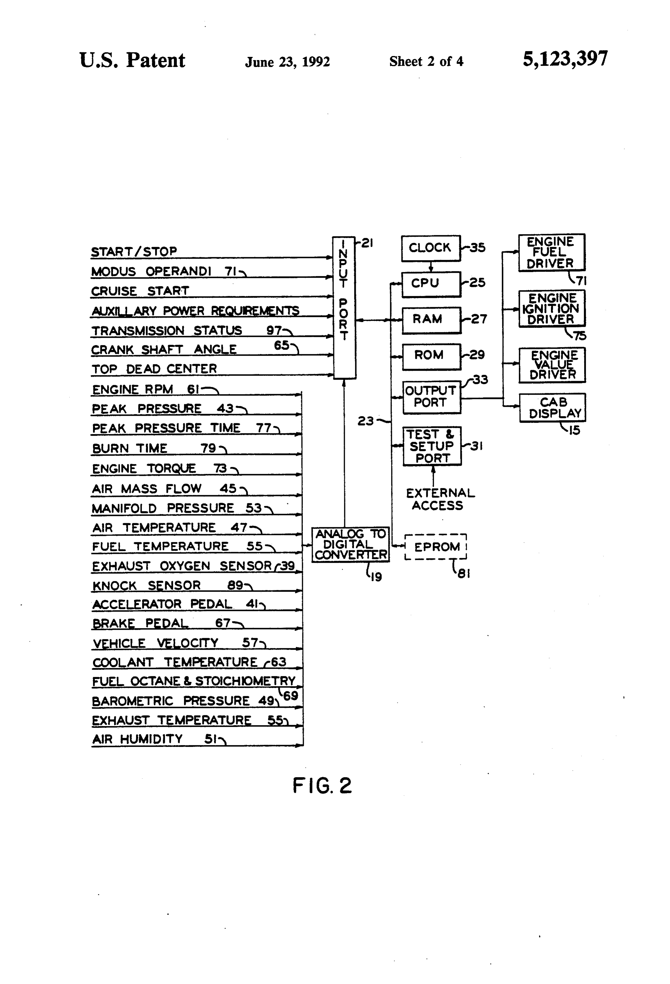
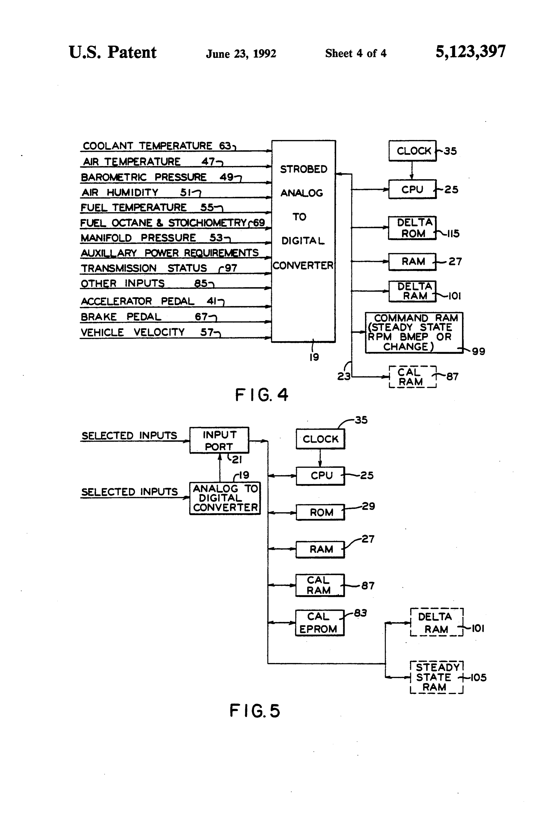
FIG. 1 is a over-all schematic diagram of a vehicle tor inputs 13, such as accelerator pedal position 41; and management computer illustrating the present invention engine performance indicators, such as crank shaft in one form and illustrating a possible set of perfor angle 65 as inputs and provides a number of operating mance indicators; parameter outputs such as ignition timing control 37 as FIG. 2 is a more detailed schematic diagram of the 55 well as a display 15 of the current status of a number of vehicle engine operational processor of FIG. 1; the input indicators. The operator inputs and some of FIG. 3 is a more detailed schematic diagram of the the vehicle performance indicators determine the vehi valve control system of FIG. 2, and, in particular, the cle operational profile 17. The system generally oper steady state operational profile; ates in an open loop fashion with closed loop operation FIG. 4 is a more detailed schematic diagram of the being only occasionally used during times of near valve control system of FIG. 2, and, in particular, the steady state operation a during cruise. corrective (command and delta) operational profile; and The several condition sensors employed in the pres FIG. 5 is a more detailed schematic diagram of the ent invention are per se known, generally analog de valve control system of FIG. 2, and, in particular, the vices. In FIG. 2, these inputs first pass through an ana calibration operational profile. 65 log to digital converter 19 which, in conjunction with Corresponding reference characters indicate corre input port 21 which may directly receive further digital sponding parts throughout the several views of the inputs, functions to supply input information on a time drawing. sequenced basis to the main bus 23. Thus, each digital
Page 9
input indicator has its own unique time slot as defined emissions. To avoid misfire, the most lean cylinder by a central processing unit or CPU 25. Bus 23 provides would be run slightly more rich than its lean burn limit. two way communication between the central process Under these circumstances, depending on the variation ing unit 25, a random access memory 27 a read-only between cylinders, the most richly operating cylinder memory 29 and a test and setup port $1 for external may be too rich. Increasing the dimension of the vector access to the system. Bus 23 also provides one-way space by one allows for storage of a plurality of differ communication by way of the output port 33 for con ent valve actuation time determining values and selec trolling the engine parameters and providing the display tion of the value for a particular valve best suited to the 15 of FIG. 1. The function of the operational processor current operating traits. In this case, the current engine of FIG. 2 under steady state conditions is shown in 10 operating traits should include traits indigenous to indi greater detail in FIG. 3. vidual ones of the engine cylinders, such as peak cylin In FIG.3, a master clock 35 provides timing pulses to der pressure 43. As an alternative, an offset or correc the central processing unit 25 which in turn synchro tion factor could be computed for each cylinder and nizes operation of the other components. Bi-directional applied to the value yielded by the table. Of course, the communication between CPU 25 and steady state read 5 other cylinder parameters such as ignition timing may only memory 103, steady state random access memory also be individually controlled.
105, operating random access memory 107, command It will be recognized that these tables can consume random access memory 99, delta random access men considerable space in the RAM 27 and ROM 29. Effi ory 101 and a calibration random access memory 87 is cient utilization of memory may dictate that n be re all by way of bus 23. It will be understood that while the duced, i.e., that some of the less important environnen several random access memories are depicted as sepa tal or performance indicators be omitted. Memory may rate, several or all may be portions of a larger memory also be conserved by range encoding the particular shown generally as 27. Similarly, the steady state read inputs. For example, the values of the vector dimension only memory 103 and other read only memories to be corresponding to engine RPM could be the integers discussed later may be separate memories or portions of 25 from one to 7 with one corresponding to the range from a larger shared read only memory 29. idle to 1200 RPM, two corresponding to 1200-1600 The steady state read only memory 103 stores a table RPM, and successive integers assigned to each interval or tables of engine operating parameters. The table or of 400 RPM up to seven which would indicate over tables are determined for a particular make and model 3200 RPM. Such range encoding of any of the inputs is of vehicle, i.e., are factory determined. For given values 30 a balancing of accuracy against memory space and of the input environmental conditions, operator inputs speed of the table look-up operation. and performance indicators, a set of operating parame The n inputs are not necessarily independent, that is, ters is read from memory 103 and stored in steady state certain ones may be computed from others. Vehicle random access memory 105. The operating parameter acceleration 113 of FIG. 1, for example, may be con values stored in memory 105 are modified as necessary 35 puted from timed repeated samplings of velocity 57 in accordance with the information in the delta randon rather than directly measured. In some cases, this is access memory 101 and in the command random access dictated by the nature of the transducer used to sense memory 99 and the values as thus modified are stored in the input condition. As one example, reasonably priced operating random access memory 107 for current en present day sensors for determining oxygen content in gine control. Particular engine operating parameters are 40 the exhaust (input line 39) are too slow acting for rapid read from the operating memory 107 and sent to the changes in engine demand situations and therefore that output port 33 which may include shift registers 107 and input is not used in FIG. 4. These sensors are, however, 109 with gated outputs and a counter duration genera adequate for long term updating of the system and tor 111 for fuel injection and from there are used to therefore used in the long term "tuning' of the engine as appropriately actuate the pertaining driver such as igni 45 in FIG. 5. Of course, for any particular engine-vehicle tion driver 75. installation certain of the inputs may be omitted, while Regardless of the actual way in which the tabular for other inputs, it may be important to sense not only data for a particular vehicle and engine is stored in the input value, but also its rate of change. As an exam memory 103, the information may be thought of as ple of the latter, one of the n inputs 41 is accelerator several independent n-dimensional vector spaces where 50 pedal position, but for rapid modification of the engine each dimension corresponds to a particular perfor operating parameters, it may be desirable to know not mance indicator, operator input, or environmental con only that the operator has depressed the pedal, but also dition, and the value of a vector in a particular space as that it was depressed rapidly (the first derivative of determined by the values of each of its dimensions cor pedal position) as in emergency passing of another vehi responds to a particular vehicle operating parameter. 55 cle. It may also be desirable to know that the pedal was The information may also be thought of as a single n-1 depressed rapidly initially and then more slowly later dimensional vector space or array with the n dimen on (the second derivative of pedal position with respect sions again corresponding to the input information and to time). The particular inputs used represent a trade off the additional dimension serving to identify the particu between ideal vehicle management and available mem lar operating parameter such as ignition time or intake ory space along with other economic considerations. valve opening time. FIG. 4 shows the sources of corrective measures to Cylinder to cylinder variations are one major prob be placed in the delta random access memory 101 to lem in controlling emissions and maximizing economy. modify the fuel, ignition and valve control information These are due to non-identical air and fuel ingestion, found in the steady state read only memory 103 and differences in compression ratio and other variations. If 65 then stored in the operating random access memory the approach to emission control is to run lean burn, the 107. The instructions in the read only memory 115 are most lean cylinder may be operated near its lean burn for a given RPM, and effective torque produced by the limit close to misfire which would greatly increase engine when operating at a given engine coolant tem
Page 10
perature; inlet air temperature, barometric pressure and ing efficiency, but these and some of the other sensors relative humidity; and other engine operating traits or possess relatively long time constants and are most conditions. When these conditions change, the informa useful in long term adjustment of the operating charac tion read from read only memory 115 is modified ac teristics of the engine. To avoid these long time con cordingly and stored in delta random access memory stant problems, the present system operates the engine 101 and then transferred to the current operating infor based on the information in the steady state ROM 103 as mation random access memory 107 and used for engine updated (see FIG. 5) or calibrated in the calibration control. Such modifications are generally speaking to RAM 87. Immediate or short term changes in the en account for changes in the environment of the vehicle. gine operational requirements are effected primarily by An indication of the indicated mean effective pres 10 the portion of the system depicted in FIG. 4. sure and RPM 61 are used to control the required fuel The delta ROM 115 of FIG. 4 is a factory set map of and the derived ignition time. One approach is to mea appropriate responses to operator indicated changes sure air mass flow 45 directly, or to measure the baro such as depression of the accelerator or brake pedal for metric pressure 49, temperature 47 and intake manifold given current operating conditions. It may, of course, pressure 53 and then compute the indicated mean effec 5 be a portion of the general ROM 29 of FIG. 2. This map tive pressure (without combustion). In either case, cor or table is transferred to and updated in delta RAM 101 rections should be made taking the relative humidity 51 which may be a portion of the general RAM 27 of FIG. into consideration. In order to control the fuel driver 2 which provides the current operating information. 71, the fuel temperature 55 and fuel octane 69 should be Part of the delta RAM information has to do with considered. Another approach is to measure engine 20 selection of certain vehicle negative accelerations shaft torque 73, and a still further approach is to set the where decisions are made to use less than the full con air to fuel ratio based on the use of an oxygen sensor plement of cylinders of the engine for power. The cylin measuring the oxygen content 39 of the exhaust. Each ders not used are put inte adiabatic no fuel operation. of these approaches works well under steady state con This condition is signaled by the operator backing off ditions, although each has its own limitations. 25 the accelerator pedal and/or, later, operation of the Under conditions of suddenly increasing loads, the brake pedal progressively placing the engine into an already difficult to interpret pulsating intake manifold energy absorbing air compressor mode. Removing pres pressure 53 with its reversing flow pulses becomes even sure on the brake pedal and depression of the accelera more difficult to filter and evaluate. This results in sig tor progressively puts the engine back into a power nificant delays in determining the required spark (37) 30 mode. When the same pattern of variations occurs dur advance and determining the required fuel to control ing operation as it did during the original mapping, the (111) the fuel to air ratio at the proper enriched operat delta RAM 101 corrections are applied to the steady ing point. If an air mass flow sensor 45 is used, the slow state RAM 105 Again, RAM 105 may be a portion of response time creates significant measurement and con the general RAM 27.
trol problems. These inputs are useful for long term or 35 In addition to the brake 67 and accelerator 41 posi slow updating of the tables, but for rapid response, if the tions, the circuit of FIG. 4 is controlled by RPM and engine torque 73 and RPM. 61 are known, then the perhaps other measures supplied by the steady state position, change in position, rate of change of position circuit of FIG. 3 and stored in command RAM 99 and and the acceleration of the rate of change of position of the other inputs illustrated in FIG. 4. As noted earlier, the accelerator pedal provides immediate useful infor 40 the several derivatives of pedal positions may be mea mation for transition operation. The transition response sured by periodic sampling of the inputs on lines 41 and of the engine is also affected by the status of the trans 67.
mission 97 and the kinetic energy of the vehicle which A test and set-up port 31 is shown in FIGS. 2 and 3. is proportional to the square of the velocity 57. This port allows data and command access to the main FIG. 2 illustrates a number of alternative vehicle 45 bus 23 so that operational tests may be performed and traits and other input information which may be used in data can be entered into the EPROM 81 and in particu the control of the engine. The cylinder peak pressure lar, the CAL EPROM 83 of FIG. 5.
43, the time 77 at which that peak pressure occurs, and The calibration computer of FIG. 5 obtains sensor the burn time 79 may all be measured using a cylinder data such as shown in FIG. 2 and, in the preferred pressure sensor. Thus, while shown as three separate 50 realization, the data shown in FIGS. 3 and 4. The other inputs 43, 77 and 79, the actual input may be from pres data line 85 may include a variety of overall perfor sure sensors in one or more of the cylinders which are mance measures such as exhaust oxygen 39, exhaust gas periodically sampled and the information computed temperature 59, knock sensing 89, flame rate, combus therefrom. This same principle may be applied to other tion chamber ionization measures, peak pressure time inputs such as the accelerator pedal position and its 55 77, or burn time 79. These measurements typically have several derivatives discussed above. An ionization long time constants or variations which require averag (flame conduction) sensor in a cylinder can also provide ing either of which entails delay and causes difficulties a measure of burn time 79, however, this measure is in direct real time utilization of the measurements to sometimes difficult to obtain under all engine operating control an engine. One problem has been that the de conditions. Engine torque 73 can also be measured di sired vehicle dynamic responses are fast while the time rectly, however, this and cylinder pressure sensors are, responses of these sensors are slow and surging or oscil at the present time, relatively expensive. Exhaust oxy lation has been very difficult to control. To avoid such gen sensors 39 are commercially available and work problems, the approach of the present invention utilizes relatively well, but they must be up to near steady state the calibration computer of FIG. 5 to classify various operating temperature before valid results are obtained. dynamic states, measure the mean responses of the delta They have a slow time response and are also subject to and steady state controls, and to determine from over ageing causing inaccurate indications. Exhaust gag tem all performance data in EPROM 83 what recalibrations perature is quite useful as an indication of engine operat are necessary. These recalibrations are created slowly,
Page 11
stored in calibration RAM 87 and periodically trans exhaust and intake gases which mixing is characteristic ferred to the steady state operating RAM 107 to modify of conventionally valved engines during the traditional the control of the engine. Thus, the system slowly con valve overlap periods.
verges to an individual engine's optimum ignition tin Closing the intake valve at a precise point in the cycle ing, air to fuel ratio, and valve timing. In the main, 5 will increase low engine speed torque by stopping the however, valve control mapping will be relatively sta reverse flow of the intake mixture back into the intake tionary in its profile depending on engine RPM and manifold which occurs in conventionally valved en torque for a given engine. Aircraft applications, for gines at low RPM. Elimination of this exchange of example, might employ a different map to accommo gasses will have a highly desirable impact on operation date engine temperature excursions and altitude varia O of the engine such as allowing low speed operation of tions along with different performance demands during the engine with higher volumetric efficiency as well as take-off, climb and cruise. Such engine operation opti greatly improving the starting and low temperature mization in response to a set of requirements in conjunc engine operation. The controlled sudden opening of the tion with other conditions can be used to optimize oper intake valve is advantageous in increasing and control ation of an engine for a variety of applications such as 15 ling turbulence and improving the mixing of fuel and air trucking, boating and other mobile or fixed engine envi during the charging cycle. At low engine speeds, more rolents. turbulence is needed for fast burns whereas at higher There are a number of ways that the approximately engine RPM higher turbulence would only serve to correct amount of fuel can be determined and added to increase heat losses, hence, the turbulence support the intake air of an automobile engine to generally get 20 should be varied. This turbulence concept is also appli satisfactory drivability when the vehicle is under heavy cable to Diesel engines especially during low speed, acceleration, is operated under general driving condi high torque operation where lack of proper burning tions, or is operated in cruise conditions. The main creates smoke and particulate pollution. High turbu problem is to get very good vehicle drivability or en lence under these conditions greatly improves engine gine operation under all of the static and dynamic oper 25 performance. More rapid opening of the exhaust valve ating conditions and yet maximize economy and mini will reduce the heretofore necessary lead time in start mize emissions. The main root of the problem is in the ing exhaust blow down in the expansion stroke. The long time constants in sensing the intake air mass flow later opening of the exhaust valve extends the power rate so that the fuel can be properly adjusted. Instead of stroke, reduces carbon monoxide and hydrocarbon using a throttled manifold engine with variable air den 30 emissions due to lessened quenching, and reduces sities, sensing problems and pumping losses, an unthrot pumping losses as well as lowering exhaust gas tempera tled variable valve engine can be used and the air con ture. The rapid opening of the exhaust valve near bot sumed can be more rapidly and accurately determined. tom dead center also creates mass flow effects which The options and advantages of the vehicle manage yield recovered energy in the crankshaft by a subatmo ment system are now feasible at least in part because of 35 spheric exhaust gas venting stroke. Exhaust gas driven the reduced valve throttling losses, the reduced heating superchargers are known, but are ineffective at lower of the exhaust valve, the separate control of opening engine speeds. Such an exhaust gas driven supercharger and closing times, and valve timing optimization to may be used in conjunction with the present invention control as well as maximize engine output and effi to provide low speed, high torque operation. For exam ciency. In the region of overlap of present valving sys 40 ple, in the case of a combustion ignited internal combus tems there is an exchange of gas from the exhaust port tion engine, a rapid opening and/or an early opening of to the intake manifold due in large measure to the low the exhaust valve significantly enhances supercharger pressure of the intake manifold causing, in part, heating response at low speed operation. With either spark of the intake valve and affecting, among other things, ignited or compression ignited internal combustion en fuel evaporation which contributes to deposit buildup 45 gines, the exhaust valve may be opened earlier at any on the intake valve. This affects engine respiration and engine speed to shorten the time required for intake air can reduce volumetric efficiency. The present invention pressure boost from the exhaust gas operated super times and controls rapidly operating, low throttling charger. When rapid attack, low speed manifold boost valves so that valve overlap may be less often used along with late opening of the intake valve is used, greatly improving this situation. When overlap is not SO cylinder turbulence can be increased to enhance clean used, fuel enrichment can be eliminated. Rapid valve burning under high fuel injection levels The more rapid operation will give rise to reduced pumping losses, the opening and closing of the exhaust and intake increased volumetric efficiency, and allow for control valves, the higher the fluidynamic resonance Q factor, ling the expansion ratio of the engine power stroke. In which will control and increase volumetric efficiency particular, instead of controlling the engine by throt 55 throughout the engine's operating range. Improvement tling the intake manifold thereby operating the engine in in the volumetric efficiency of air compressors under a vacuum pump or variable intake density mode, the variable operating circumstances is also possible with engine, and in particular the cylinder charge, may be such intake and exhaust valve arrangements. The more controlled by governing the duration of time the intake rapid opening of the exhaust valve in the internal com valve is open followed by an adiabatic expansion and 60 bustion engine, with less throttling and the reduction of compression, or by controlling the net time during the the peak velocity of the boundary layer of the hot gasses cycle that the intake valve is open as opposed to throt past the valve will reduce heat transfer from the exhaust tling the intake to the engine. gases to the valve allowing the valve to run cooler, Opening the intake valve at a controlled time (depen improving valve life particularly under highly oxidizing dent on patterns of vehicle performance and other indi 65 lean burn, high power and high temperature conditions. cators) such as in the order of 10 to 70 degrees after top When used in conjunction with an exhaust gas driven dead center and closing at the appropriate time in supercharger, more exhaust gas energy can be recov creases volumetric efficiency and prevents mixing of ered to increase supercharger output. The reduced ex
Page 12
haust gas quenching will reduce unburned hydrocarbon quired to get the demanded power level. Leaner burns and carbon monoxide concentration in the exhaust. can be used on the remaining cylinders due to the The exhaust gases that are normally emitted near the higher pressures and temperatures allowing higher igni end of the exhaust stroke are rich in unburned hydro tability and higher propensity of burning of the charge. carbons due to scavenging effects of the unburned Reduction of unburned hydrocarbon emissions dur boundary layers close to the cooler combustion cham ing deceleration is also possible. Conventionally valved ber walls and the boiling of unburned hydrocarbons out engines develope high intake manifold vacuum during of cavities such as around the head gasket and around deceleration which enhances fuel evaporation on the the piston and its compression rings that were deposited manifold inner surface resulting in an overly rich mix there due to pressurization of the charge due to the 10 ture being burned. In particular, charging of the cylin compression stroke and burning charge pressurization. ders is controlled in the present invention by intake Rapid closing of the exhaust valve will retain more of valve openings and closings and the intake manifold is these emission rich gases for reburning and the control not under variable vacuum and hence does not exhibit of exhaust valve opening that controls the expansion the same effects. Further, the overly rich low density ratio of the engine will go toward greatly reducing or 15 cylinder charge in the conventional engine mag not eliminating the need for the catalytic converter. The use ignite or burn as completely as it does under higher of controlled exhaust gas retention can also eliminate charge levels, hence, causing high unburned hydrocar the present exhaust gas recirculating devices. bon emissions. Engines equipped with the present elec Precise differential electronic control of the opening tronically controllable valve arrangement may be used and closing times of the valves allows a control of the to aid normal or rapid deceleration by closing selected mass flow through the intake and exhaust valves in valves for operation using fewer than the full comple various operating modes with a resulting reduction of ment of cylinders or no powered cylinders allowing for undesirable emissions, increase in volumetric efficiency vehicle slow down due to the rolling friction and aero and generally allows an optimization of engine perfor dynamic losses under conditions where engine output is mance. Differential control of ignition and fuel can 25 selectively less that the frictional losses, or cause the allow all cylinders to be essentially identical thereby engine to absorb power in an air compressor mode. allowing a closer approach to the lean burn limit or to When spark, fuel and valving are controlled, heat other critical points. Such precise electronic control can recovery by controlling air intake temperature is facili facilitate a number of further modifications including tated. For example, high heat recovery may be used the fact that all cylinders may be purged with fresh air 30 when the combustion temperature is low as when oper during shut down and that all valves may be closed ating the engine well below maximum torque. Such heat when the engine is not in use, thereby eliminating expo recovery may also help control combustibility under sure to the atmosphere and reducing corrosion within lean or high exhaust gas retention conditions. Ideally, the combustion chambers due to residual gasses, con the combustion temperature would be held to a prede densates and oxides of nitrogen. 35 termined maximum where one would have the best Initial cranking to start the engine may be performed entropy position but yet controlled NOX production. with appropriate valves maintained open until cranking Reduced hydrocarbon emission results from higher speed is sufficiently high. This provides a "compres expansion ratio, less quenching at the exhaust valve, sionless' cranking to aid cold weather starting. Cold reduced exhaust gas blow-down time, lower emission at engine starting and running during the warm-up period the end of the exhaust stroke as well as during decelera without consuming excessive fuel is made possible by tion, and generally less valve overlap operation as well 6-cycle operation where one additional compression as lean burn and programming the engine to use fewer and expansion are used to vaporize the fuel. This ap than the full complement of cylinders when possible. proach will greatly assist in the use of low volatility These combine to greatly reduce the need for catalytic (low Reed vapor pressure) fuels that are safer and pro 45 converters. General improvement in efficiency may be vide less evaporation to the atmosphere. This 6-cycle achieved by increased and controllable expansion of the mode of operation is described in greater detail in the power stroke gases resulting, in part, from the very abovementioned Ser. No. 153,257 PNEUMATIC rapid opening of the present valve arrangement. The ELECTRONIC VALVE ACTUATOR application. conventional exhaust valve may begin to open at 45 to This facilitates cold engine starting with the present 50 80 degrees before botton dead center (for a 0.01 inch fuels and the future low volatility fuels and cold engine seat clearance) and at 60 or more psi gas pressure in running as well as reducing unburned hydrocarbon order to achieve the momentum of the gas mass neces emission prior to the time when a catalytic converter sary to evacuate the exhaust gases against a great deal of can be lighted. Such converters are ineffective until exhaust gas valve port throttling. The valve of the pres they reach an elevated operating temperature. Emission 55 ent invention may be opened at near bottom dead center of unburned hydrocarbons from engine start-up and to utilize more of the expansion during the power coming up to temperature will be greatly reduced. stroke. The conventional engine exhaust valve may Leaving the cylinders of an up to temperature engine in close 45 degrees after top dead center with the corre appropriately charged states coupled with proper intro sponding intake valve opening 20 to 40 degrees before duction of ignition spark, allows the engine to be re 60 top dead center resulting in perhaps 70 degrees of over started without cranking when the engine has been lap where charge diluting exhaust is pulled into the stopped for a short time period, such as sitting at a stop intake manifold and then back into the cylinder result light. ing in charge heterogeneity and hence lean burn ignita Control of the number of cylinders in use, as during bility and burning problems. With the present inven steady state cruse on a highway, or other low demand 65 tion, there is, in general, no such overlap between the condition allows the active cylinders to be operated intake and exhaust valves and, hence there are less prob more efficiently because of the superior entropy due to lems with developing heterogeneous charges and ex higher burn pressures and temperatures that are re tending the lean burn limit.
Page 13
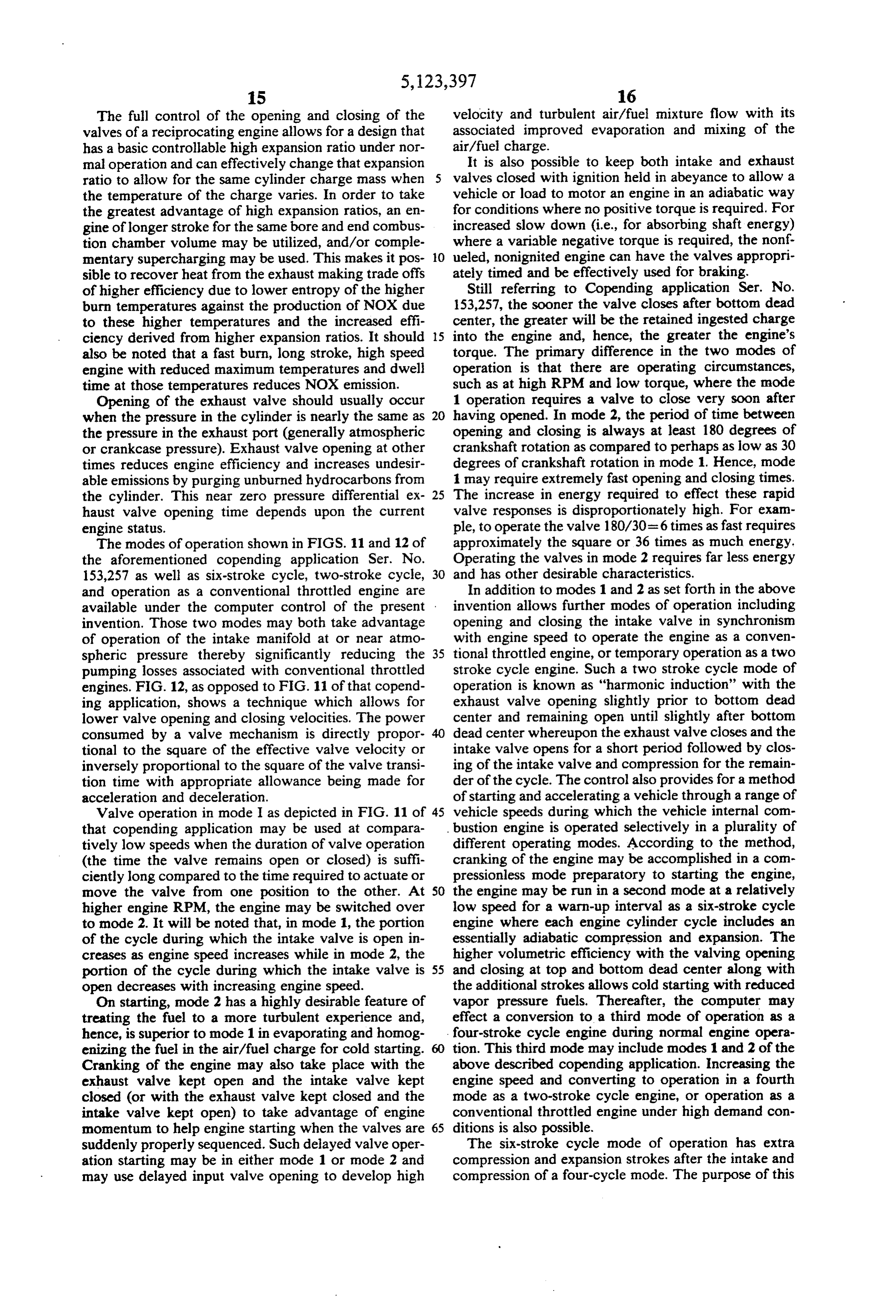
The full control of the opening and closing of the velocity and turbulent air/fuel mixture flow with its valves of a reciprocating engine allows for a design that associated improved evaporation and mixing of the has a basic controllable high expansion ratio under nor air/fuel charge.
mal operation and can effectively change that expansion It is also possible to keep both intake and exhaust ratio to allow for the same cylinder charge mass when valves closed with ignition held in abeyance to allow a the temperature of the charge varies. In order to take vehicle or load to motor an engine in an adiabatic way the greatest advantage of high expansion ratios, an en for conditions where no positive torque is required. For gine of longer stroke for the same bore and end combus increased slow down (i.e., for absorbing shaft energy) tion chamber volume may be utilized, and/or comple where a variable negative torque is required, the nonf mentary supercharging may be used. This makes it pos 10 ueled, nonignited engine can have the valves appropri sible to recover heat from the exhaust making trade offs ately timed and be effectively used for braking. of higher efficiency due to lower entropy of the higher Still referring to Copending application Ser. No. burn temperatures against the production of NOX due 153,257, the sooner the valve closes after bottom dead to these higher temperatures and the increased effi center, the greater will be the retained ingested charge ciency derived from higher expansion ratios. It should 15 into the engine and, hence, the greater the engine's also be noted that a fast burn, long stroke, high speed torque. The primary difference in the two modes of engine with reduced maximum temperatures and dwell operation is that there are operating circumstances, time at those temperatures reduces NOX emission. such as at high RPM and low torque, where the mode Opening of the exhaust valve should usually occur 1 operation requires a valve to close very soon after when the pressure in the cylinder is nearly the same as 20 having opened. In mode 2, the period of time between the pressure in the exhaust port (generally atmospheric opening and closing is always at least 180 degrees of or crankcase pressure). Exhaust valve opening at other crankshaft rotation as compared to perhaps as low as 30 times reduces engine efficiency and increases undesir degrees of crankshaft rotation in mode 1. Hence, mode able emissions by purging unburned hydrocarbons from 1 may require extremely fast opening and closing times. the cylinder. This near zero pressure differential ex 25 The increase in energy required to effect these rapid haust valve opening time depends upon the current valve responses is disproportionately high. For exam engine status. ple, to operate the valve 180/30=6 times as fast requires The modes of operation shown in FIGS. 11 and 12 of approximately the square or 36 times as much energy. the aforementioned copending application Ser. No. Operating the valves in mode 2 requires far less energy 153,257 as well as six-stroke cycle, two-stroke cycle, 30 and has other desirable characteristics. and operation as a conventional throttled engine are In addition to modes 1 and 2 as set forth in the above available under the computer control of the present invention allows further modes of operation including invention. Those two modes may both take advantage opening and closing the intake valve in synchronism of operation of the intake manifold at or near atmo with engine speed to operate the engine as a conven spheric pressure thereby significantly reducing the 35 tional throttled engine, or temporary operation as a two pumping losses associated with conventional throttled stroke cycle engine. Such a two stroke cycle mode of engines. FIG. 12, as opposed to FIG. 11 of that copend operation is known as "harmonic induction' with the ing application, shows a technique which allows for exhaust valve opening slightly prior to bottom dead lower valve opening and closing velocities. The power center and remaining open until slightly after bottom consumed by a valve mechanism is directly propor 40 dead center whereupon the exhaust valve closes and the tional to the square of the effective valve velocity or intake valve opens for a short period followed by clos inversely proportional to the square of the valve transi ing of the intake valve and compression for the remain tion time with appropriate allowance being made for der of the cycle. The control also provides for a method acceleration and deceleration. of starting and accelerating a vehicle through a range of Valve operation in mode I as depicted in FIG. 11 of 45 vehicle speeds during which the vehicle internal com that copending application may be used at compara bustion engine is operated selectively in a plurality of tively low speeds when the duration of valve operation different operating modes. According to the method, (the time the valve remains open or closed) is suffi cranking of the engine may be accomplished in a com ciently long compared to the time required to actuate or pressionless mode preparatory to starting the engine, move the valve from one position to the other. At 50 the engine may be run in a second mode at a relatively higher engine RPM, the engine may be switched over low speed for a warn-up interval as a six-stroke cycle to mode 2. It will be noted that, in mode 1, the portion engine where each engine cylinder cycle includes an of the cycle during which the intake valve is open in essentially adiabatic compression and expansion. The creases as engine speed increases while in mode 2, the higher volumetric efficiency with the valving opening portion of the cycle during which the intake valve is 55 and closing at top and bottom dead center along with open decreases with increasing engine speed. the additional strokes allows cold starting with reduced On starting, mode 2 has a highly desirable feature of vapor pressure fuels. Thereafter, the computer may treating the fuel to a more turbulent experience and, effect a conversion to a third mode of operation as a hence, is superior to mode 1 in evaporating and homog four-stroke cycle engine during normal engine opera enizing the fuel in the air/fuel charge for cold starting. tion. This third mode may include modes 1 and 2 of the Cranking of the engine may also take place with the above described copending application. Increasing the exhaust valve kept open and the intake valve kept engine speed and converting to operation in a fourth closed (or with the exhaust valve kept closed and the mode as a two-stroke cycle engine, or operation as a intake valve kept open) to take advantage of engine conventional throttled engine under high demand con momentum to help engine starting when the valves are 65 ditions is also possible.
suddenly properly sequenced. Such delayed valve oper The six-stroke cycle mode of operation has extra ation starting may be in either mode 1 or mode 2 and compression and expansion strokes after the intake and may use delayed input valve opening to develop high compression of a four-cycle mode. The purpose of this
Page 14
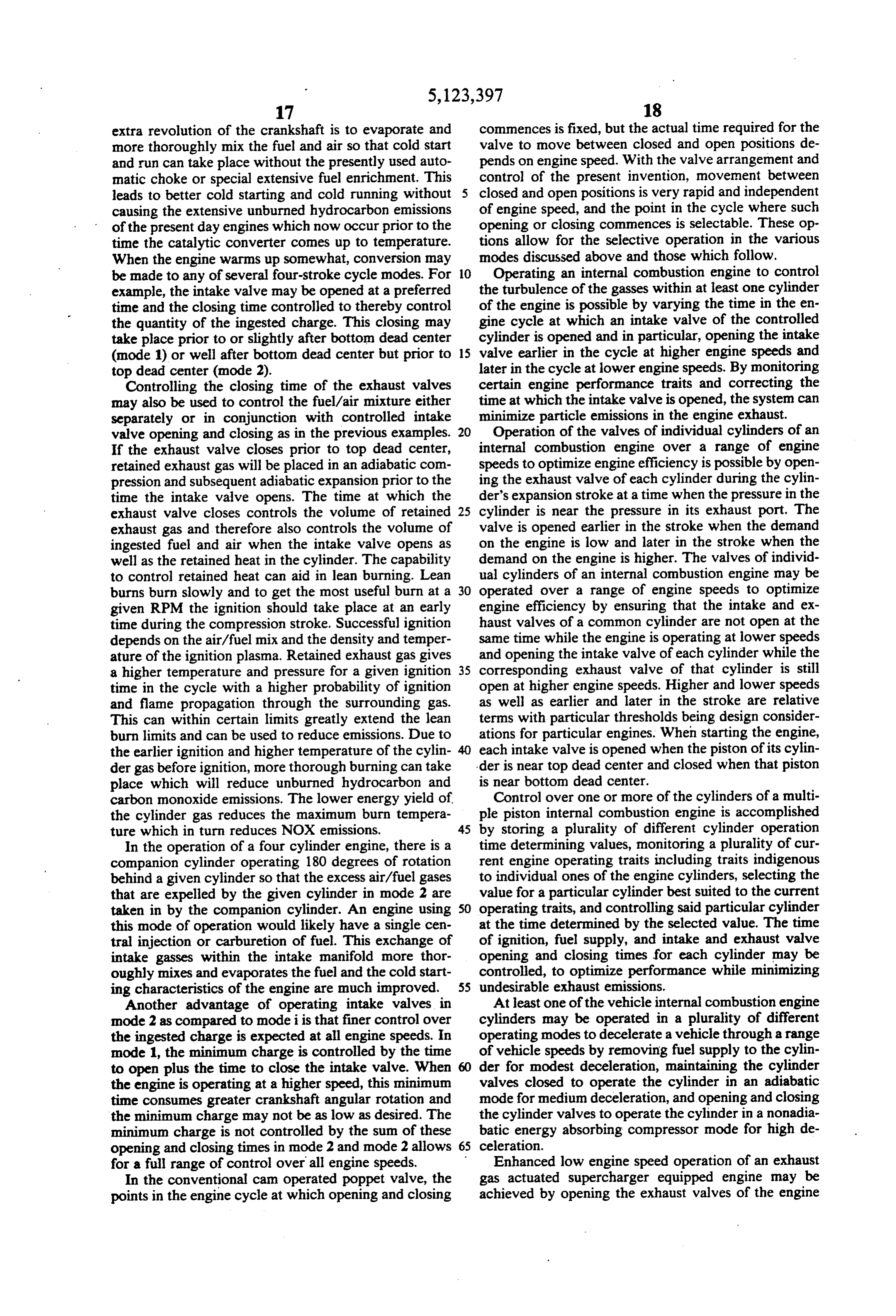
extra revolution of the crankshaft is to evaporate and commences is fixed, but the actual time required for the more thoroughly mix the fuel and air so that cold start valve to move between closed and open positions de and run can take place without the presently used auto pends on engine speed. With the valve arrangement and matic choke or special extensive fuel enrichment. This control of the present invention, movement between leads to better cold starting and cold running without 5 closed and open positions is very rapid and independent causing the extensive unburned hydrocarbon emissions of engine speed, and the point in the cycle where such of the present day engines which now occur prior to the opening or closing commences is selectable. These op time the catalytic converter comes up to temperature. tions allow for the selective operation in the various When the engine warms up somewhat, conversion may modes discussed above and those which follow. be made to any of several four-stroke cycle modes. For 10 Operating an internal combustion engine to control example, the intake valve may be opened at a preferred the turbulence of the gasses within at least one cylinder time and the closing time controlled to thereby control of the engine is possible by varying the time in the en the quantity of the ingested charge. This closing may gine cycle at which an intake valve of the controlled take place prior to or slightly after bottom dead center cylinder is opened and in particular, opening the intake (mode 1) or well after bottom dead center but prior to 15 valve earlier in the cycle at higher engine speeds and top dead center (mode 2). later in the cycle at lower engine speeds. By monitoring Controlling the closing time of the exhaust valves certain engine performance traits and correcting the may also be used to control the fuel/air mixture either time at which the intake valve is opened, the system can separately or in conjunction with controlled intake minimize particle emissions in the engine exhaust. valve opening and closing as in the previous examples. 20 Operation of the valves of individual cylinders of an If the exhaust valve closes prior to top dead center, internal combustion engine over a range of engine retained exhaust gas will be placed in an adiabatic com speeds to optimize engine efficiency is possible by open pression and subsequent adiabatic expansion prior to the ing the exhaust valve of each cylinder during the cylin time the intake valve opens. The time at which the der's expansion stroke at a time when the pressure in the exhaust valve closes controls the volume of retained 25 cylinder is near the pressure in its exhaust port. The exhaust gas and therefore also controls the volume of valve is opened earlier in the stroke when the demand ingested fuel and air when the intake valve opens as on the engine is low and later in the stroke when the well as the retained heat in the cylinder. The capability demand on the engine is higher. The valves of individ to control retained heat can aid in lean burning. Lean ual cylinders of an internal combustion engine may be burns burn slowly and to get the most useful burn at a 30 operated over a range of engine speeds to optimize given RPM the ignition should take place at an early engine efficiency by ensuring that the intake and ex time during the compression stroke. Successful ignition haust valves of a common cylinder are not open at the depends on the air/fuel mix and the density and temper same time while the engine is operating at lower speeds ature of the ignition plasma, Retained exhaust gas gives and opening the intake valve of each cylinder while the a higher temperature and pressure for a given ignition 35 corresponding exhaust valve of that cylinder is still time in the cycle with a higher probability of ignition open at higher engine speeds. Higher and lower speeds and flame propagation through the surrounding gas. as well as earlier and later in the stroke are relative This can within certain limits greatly extend the lean terms with particular thresholds being design consider burn limits and can be used to reduce emissions. Due to ations for particular engines. When starting the engine, the earlier ignition and higher temperature of the cylin 40 each intake valve is opened when the piston of its cylin der gas beforeignition, more thorough burning can take der is near top dead center and closed when that piston place which will reduce unburned hydrocarbon and is near bottom dead center.
carbon monoxide emissions. The lower energy yield of Control over one or more of the cylinders of a multi the cylinder gas reduces the maximum burn tempera ple piston internal combustion engine is accomplished ture which in turn reduces NOX emissions. 45 by storing a plurality of different cylinder operation In the operation of a four cylinder engine, there is a time determining values, monitoring a plurality of cur companion cylinder operating 180 degrees of rotation rent engine operating traits including traits indigenous behind a given cylinder so that the excess air/fuel gases to individual ones of the engine cylinders, selecting the that are expelled by the given cylinder in mode 2 are value for a particular cylinder best suited to the current taken in by the companion cylinder. An engine using 50 operating traits, and controlling said particular cylinder this mode of operation would likely have a single cen at the time determined by the selected value. The time tral injection or carburetion of fuel. This exchange of of ignition, fuel supply, and intake and exhaust valve intake gasses within the intake manifold more thor opening and closing times for each cylinder may be oughly mixes and evaporates the fuel and the cold start controlled, to optimize performance while minimizing ing characteristics of the engine are much improved. 55 undesirable exhaust emissions.
Another advantage of operating intake valves in At least one of the vehicle internal combustion engine node 2 as compared to mode i is that finer control over cylinders may be operated in a plurality of different the ingested charge is expected at all engine speeds. In operating modes to decelerate a vehicle through a range mode 1, the minimum charge is controlled by the time of vehicle speeds by removing fuel supply to the cylin to open plus the time to close the intake valve. When der for modest deceleration, maintaining the cylinder the engine is operating at a higher speed, this minimum valves closed to operate the cylinder in an adiabatic time consumes greater crankshaft angular rotation and mode for medium deceleration, and opening and closing the minimum charge may not be as low as desired. The the cylinder valves to operate the cylinder in a nonadia minimum charge is not controlled by the sum of these batic energy absorbing compressor mode for high de opening and closing times in mode 2 and mode 2 allows 65 celeration.
for a full range of control over all engine speeds. Enhanced low engine speed operation of an exhaust In the conventional cam operated poppet valve, the gas actuated supercharger equipped engine may be points in the engine cycle at which opening and closing achieved by opening the exhaust valves of the engine
Page 15
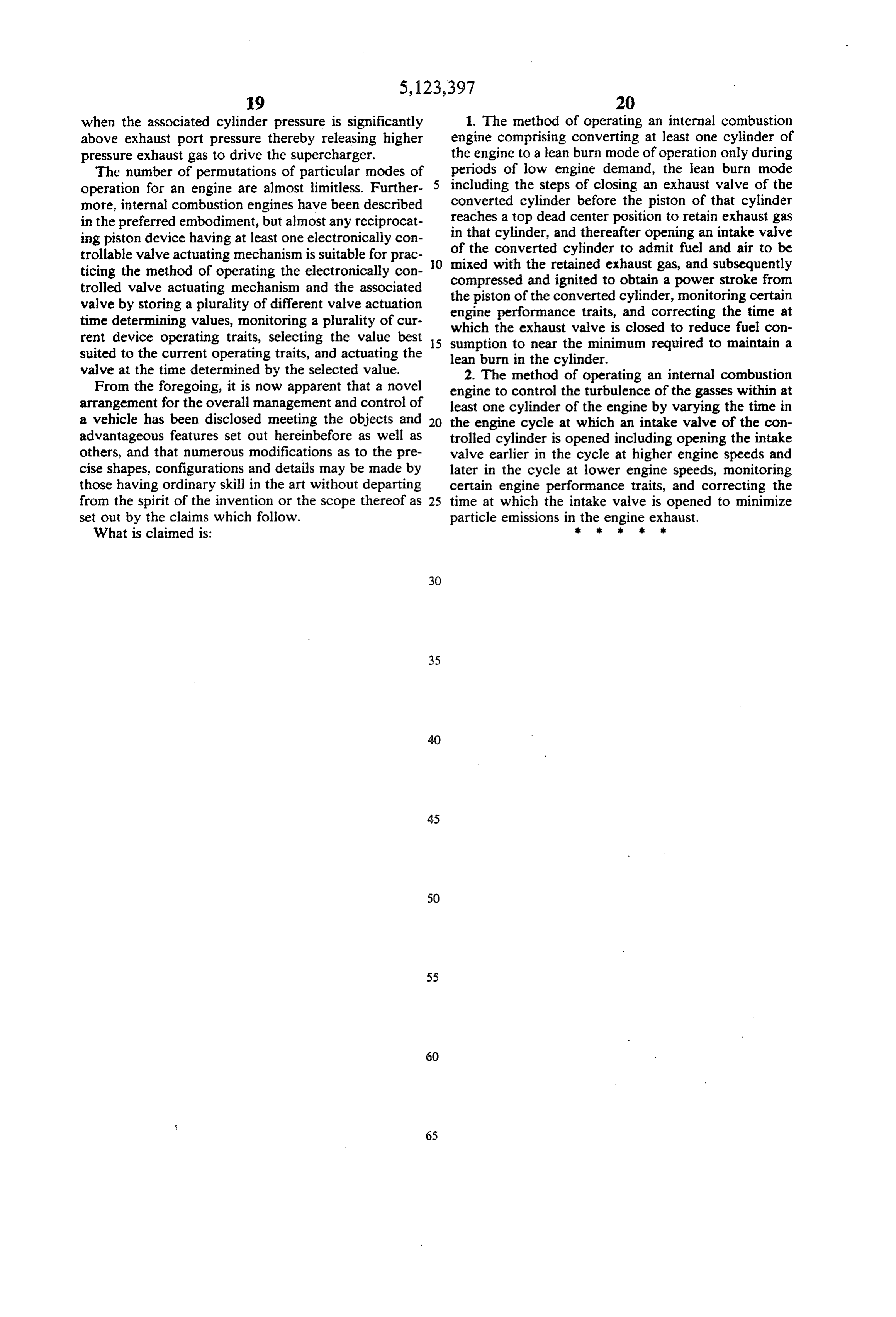
when the associated cylinder pressure is significantly 1. The method of operating an internal combustion above exhaust port pressure thereby releasing higher engine comprising converting at least one cylinder of pressure exhaust gas to drive the supercharger. the engine to a lean burn mode of operation only during The number of permutations of particular modes of periods of low engine demand, the lean burn mode operation for an engine are almost limitless. Further 5 including the steps of closing an exhaust valve of the more, internal combustion engines have been described converted cylinder before the piston of that cylinder in the preferred embodiment, but almost any reciprocat reaches a top dead center position to retain exhaust gas ing piston device having at least one electronically con in that cylinder, and thereafter opening an intake valve trollable valve actuating mechanism is suitable for prac O of the converted cylinder to admit fuel and air to be mixed with the retained exhaust gas, and subsequently ticing the method of operating the electronically con trolled valve actuating mechanism and the associated compressed the piston of and ignited to obtain a power stroke from the converted cylinder, monitoring certain valve by storing a plurality of different valve actuation engine performance traits, and correcting the time at time determining values, monitoring a plurality of cur which the exhaust valve is closed to reduce fuel con rent device operating traits, selecting the value best 15 sumption to near the minimum required to maintain a suited to the current operating traits, and actuating the lean burn in the cylinder.
valve at the time determined by the selected value. 2. The method of operating an internal combustion From the foregoing, it is now apparent that a novel engine to control the turbulence of the gasses within at arrangement for the overall management and control of least one cylinder of the engine by varying the time in a vehicle has been disclosed meeting the objects and 20 the engine cycle at which an intake valve of the con advantageous features set out hereinbefore as well as trolled cylinder is opened including opening the intake others, and that numerous modifications as to the pre valve earlier in the cycle at higher engine speeds and cise shapes, configurations and details may be made by later in the cycle at lower engine speeds, monitoring those having ordinary skill in the art without departing certain engine performance traits, and correcting the from the spirit of the invention or the scope thereof as 25 time at which the intake valve is opened to minimize set out by the claims which follow. particle emissions in rthek engine exhaust. What is claimed is:
Provenance
- Collection
- Cited prior art
- Original PDF
- patentimages.storage.googleapis.com →
- Filed
- 1990-05-10
- Pages
- 15
- Method
- pdftotext (the PDF's own text layer) + pdftoppm 300dpi page scans
- Source
- Google Patents bibliographic record
- Granted
- 1992-06-23
- Inventors
- William E. Richeson; North American Philips Corp
- Transcribed from
- patentimages.storage.googleapis.com →