patent · US5946928
Mini tube and direct expansion heat exchange system
7 September 1999
Page 1 — bibliographic record
United States Patent (19) 11 Patent Number: 5,946,928 Wiggs (45) Date of Patent: Sep. 7, 1999 54 MINITUBE AND DIRECT EXPANSION 57 ABSTRACT
HEAT EXCHANGE SYSTEM
A direct expansion geothermal heating/cooling System 76 Inventor: B. Ryland Wiggs, 425 Sims La., wherein the interior air handler is sized via 100 cubic inches Franklin, Tenn. 37069 of interior heat exchange tube volume per 12,000 BTUs of maximum design capacity; wherein the thermal expansion 21 Appl. No.: 08/915,255 Valves are sized to the tonnage capacity of the air handler's design; wherein the Subterranean heat eXchange tubing 22 Filed: Aug. 20, 1997 consists of /s inch to 3/16 inch outside diameter tubing with outside diameter to tube length ratios of between 1/6,400 (51) Int. Cl." ...................................................... F25D 23/12 and 1/9,600, and where the interior diameter to length ratios 52) ... 62/260; 165/45 are between 1/9,411 and 1/18,462; wherein the interior 58 Field of Search .................................... 62/260, 238.7, Volume of the Subterranean heat eXchange tubing is within 62/238.6; 165/45 1% of the interior volume of the interior air handler's heat eXchange tubing, wherein at least 40 Square feet of Subter 56) References Cited ranean heat eXchange tubing is proportionately exposed to a 500 square foot area of earth per 12,000 BTUs of system
2,503,456 4/1950 Smith ........................................ 62/115 heat eXchange tubes are finned, with fins Spaced at least /4 3,183,675 5/1965 Schroeder ................................... 61/36 inch apart; wherein the compressor's design capacity is 5,025,634 6/1991 Dressler ....... ... 62/79 between 20% and 33.33% less than the interior air handler's 5,224.357 7/1993 Galiyano ................................... 62/260 design; where the receiver and accumulator are about 20% 5,461,876. 10/1995 Dressler .................................... 62/160 to 50% smaller than conventionally sized; and where the 5,671,608 9/1997 Wiggs ....................................... 62/260 geothermal heat eXchange tubing is accessed via dual, or 5,758,514 6/1998 Genuing ..................................... 62/471 multiple, distributors and/or is installed in a vertical or angled slot from 1 inch to 1 foot wide, which is backfilled
Primary Examiner-Henry A. Bennett with powdered stone, heat conductive fill, flowable fill, ASSistant Examiner Melvin Jones concrete or the like.
Attorney, Agent, or Firm Waddey & Patterson; Mark J.
Patterson 13 Claims, 1 Drawing Sheet
Page 2
Drawing sheet — no readable text.
Page 3
MINITUBE AND DIRECT EXPANSION thickness), /4 inch outside diameter copper tubes for the HEAT EXCHANGE SYSTEM Subterranean heat eXchanger. These tubes had an external diameter to length ratio of 1/4,800, which ratio was taught
FIELD OF THE INVENTION and later claimed as proprietary by U.S. Pat. No. 5,025,634 The present invention relates to a wholly or partial direct to Dressler, as subsequently assigned to USPower Climate expansion heat eXchange System for use in association with Control, Inc., which manufactured and Sold direct expansion any heating/cooling System and/or power generation System systems utilizing the said 1/4,800 ratio. utilizing in-ground and/or in-water heat eXchange elements Further, USPower Climate Control, Inc., formerly of 954 as a primary or Supplemental Source of heat transfer. Marion Blvd., Allentown, Pa. 18103, during or about 1990 through 1991, also Sold direct expansion Systems utilizing
BACKGROUND OF THE INVENTION 100 foot long, ACR grade (0.032 inch wall thickness), 5/16 inch outside diameter, copper tubes for its Subterranean heat
Geothermal direct expansion heating/cooling Systems are eXchangers. These tubes had an external diameter to length generally well known Systems which are essentially “heat ratio of 1/3,840.
pumps', transferring heat via a common refrigeration cycle, 15 All of the above-referenced geothermal direct expansion from one Source to another, with at least one of two or more of the System's heat eXchange elements being buried in the groundlarger, coil designs utilize /4 inch outside diameter, or
Subterranean heat eXchange tubing, which is com ground or Submersed in water, Such as a lake or pond. monplace among all known direct expansion Systems. AS referenced, Geothermal direct expansion heating/ Further, while the Subterranean tube Surface area perton (per cooling Systems include at least one heat eXchange element, 12,000 BTUs) of heating/cooling System design capacity is typically consisting of closed loops of tubing, buried in the uncertain in Waterkote's design, all other above-referenced ground or Submersed in water. These closed loops of tubing designs utilize a combined tube Surface area of about 32.6 may be installed in a variety of manners, including horizon Square feet to 39.2 Square feet per ton of design capacity, tal configurations or helical loops, as well as in various which is typically exposed, via a network of approximately Vertical configurations, Such as Spiraled coils or elongated 25 equally Spaced and arrayed tubing, to a ground Surface area U-shaped tubes. These Subterranean tubes, or loops, typi of about 500 Square feet per ton of design capacity. cally carry a refrigerant, Such as R-22, or the like, in direct Further, in order to combat the aforesaid charge imbalance expansion heating/cooling Systems to assist in effecting heat resulting from the differing interior Volume areas in the transfer.
interior air handler heat eXchange coils versus the exterior
Regarding direct expansion Subterranean (below ground/ Subterranean heat eXchange ground coils, the use of a below water Surface) heat exchange tube sizing, it is well receiver has traditionally been employed, So as to automati known that refrigerant charge imbalances exist, in all current cally hold unnecessary refrigerant in reserve within a hold System designs, between Summer and winter Seasons. While, ing container on the high pressure Side of the compressor. ideally, refrigerant charges should be equivalent, this is 35 The charge imbalance results when one Switches the presently not the case in any known direct expansion System. System from a heating to a cooling mode, or Vise a versa. Historically, this interior volume imbalance exists Typically, in the heating mode, the exterior ground coils are between the interior air heat eXchange coils and the exterior, the evaporator Section of the System and the interior air Subterranean, heat eXchange coils. The resulting refrigerant handler coils are the condenser Section. When the System is charge imbalance has been due to three primary reasons: (1) 40 Switched to a cooling mode, the exterior ground coils the perceived notion that larger diameter Subterranean tubes become the condenser and the interior air handler coils provide greater heat transfer capacity than Smaller diameter become the evaporator. Since, with conventional geothermal tubing, which could be correct when Solely evaluating a tube direct expansion Systems, the ground coils combined interior comparison of an equal number of tubes with equal lengths Volume is greater than that of the air handler's combined but with varying interior diameters; (2) the perceived notion 45 interior Volume, more liquid refrigerant is required for that more tubing is required below ground in Subterranean efficient System operation in the cooling mode than in the finnleSS heat eXchange tubing than above ground in the fan heating mode.
assisted air handler containing finned tubing, which could be The use of a conventionally sized, or larger, receiver to correct with conventionally designed Systems since Subter automatically adjust the aforesaid charge imbalance in direct ranean tubing must be spaced over an adequate minimum 50 expansion Systems ground area, and therefore cannot normally utilize finned receiver was taught,isalthough well known. The use of a conventional tubing, which could concentrate heat eXchange in too small U.S. Pat. No. 4,688,717 tonot claimed as proprietary, by Jungwirth. A conventional an area to effectively achieve the necessary Seasonal overall receiver was reportedly used by the aforesaid Aardvark Air, System heat exchange operational efficiencies; and (3) the Inc., in direct expansion Systems during or about perceived notion that the less the number of tubes in the 55 conventional receiver was taught for use in a direct1982. expan
Subterranean heat eXchanger, the faster the installation, and sion system via a textbook entitled “Modern Refrigeration the lower the initial installation cost, which is generally and Air Conditioning” by Andrew D. Althouse, Carl H. correct with most direct expansion ground coil design lay Turnquist, and Alfred F. Bracciano, published by The OutS.
Goodheart-Willcox Company, Inc., copyright 1975. The use
AS a result, prior art has developed the following ground 60 of an oversized 20% total refrigerant quantity capacity tube size ratios: receiver in a direct expansion System was claimed as pro In DE3514191A1 to Waterkote, the use of direct expan prietary by U.S. Pat. No. 5,461,876 to Drlessler. Enviro Sion geothermal heat transfer tubing with internal diameter therm Heating and Cooling, Inc., of 105 Forrest Retreat, to length ratios of between 1/2857 and 1/3750 was taught. Hendersonville, Tenn. 37075, marketed and sold a direct Aardvark Air, Inc., formerly of 700 Prospect, Kansas City, 65 expansion system in 1995 which contained an oversized Mo. 64132, reportedly sold and installed direct expansion receiver designed to store close to 50% of the total refrig systems utilizing 100 foot long, ACR grade (0.03 inch wall erant quantity. However, the use of any conventionally
Page 4
sized, or larger, receiver in a direct expansion System man Surrounding Soil, or ground, which heat transfer into the dates a certain equipment manufacturing cost for both Surrounding ground is Sometimes augmented with an arti materials and labor. ficial fill material placed around the finnleSS tubing, Such as Regardless of the extra equipment and manufacturing powdered Stone, concrete, flowable fill, or the like. cost, Standard or oversized receivers are necessary in cur Yet another problem typically encountered with conven rently designed direct expansion Systems in order to reduce tional direct expansion Systems arises from the use of a System operational inefficiencies otherwise occurring in the Single vapor line with a single distribution point, and a single heating and/or cooling mode. In fact, if the System's refrig liquid line, with a single distribution point, to and from the erant charge Volume differential between the interior air interior equipment from and to the multiple, Smaller, Sub handler coil Volume and the Subterranean ground coil Vol terranean heat eXchange tubes. Typically, the Single vapor ume was too great, absent a receiver, the System could and liquid line Sets are kept at an equal length, and require potentially totally fail to reverse cycle (Switch to heating a congregation of the multiple Subterranean heat eXchange mode from cooling mode, or Vice a versa). tubeSat respective Single point for the vapor line and for the Regarding the Sizing and matching of System liquid line, which diminishes ground contact area with components, conventionally, direct expansion Systems have 15 naturally occurring geothermal heat. Worse, these congre been sized by a determination of the Subject Structure's gation points are often in relatively close proximity to one heating/cooling load, via ACCA Manual J, or similar, BTU another, and thereby tend to Subject the returning heat heating/cooling load calculation criteria. Thereafter, the eXchange lines to the extreme heat or cold of the outgoing compressor is sized to match the calculated BTU load, heat eXchange lines, depending on whether operating in a where one ton of capacity equals 12,000 BTUs. The air cooling or a heating cycle, thereby negating Some of the handler is sized to match the capacity of the compressor, So positively gained geothermal heat eXchange effect. A means that, for example, a manufacturers three ton compressor is of avoiding these problems would increase operational effi matched with a manufacturer's three ton air handler. The ciencies.
corresponding ground coils are also conventionally sized by Further, conventionally designed direct expansion ground the manufacturer to match the conventional compressor and 25 coils are installed in a large excavated pit, typically requiring conventional air handler Sizing. A commonly used ground a large coil design would be five 100 foot long, 4 inch diameter, hoe; in well front end loader excavator, or a large bucket track ACR grade, tubes per ton of compressor capacity. holes, either vertical or angled, typically requir Conventionally, an accumulator and a receiver, designed to ing a large well drilling rig, in a trench, typically two feet to match the conventionally sized compressor, or an oversized eight feet wide, requiring a large bucket back hoe, or track accumulator and an oversized receiver, together with ther hoe; orpole via a cylindrical design, typically requiring a tele mal expansion valves, sized to match the compressor phone ally designed drilling rig, or the like. As a result, convention direct expansion ground coils are relatively tonnage, are also utilized in direct expansion applications. expensive to install,
The best method of sizing and matching System components moving, which is and both require a significant amount of earth time-consuming and relatively is an area of critical concern for overall highly efficient 35 expensive, as well as being problematic for landscaping System operation. when an installation occurs where there is an established Lastly, none of the above-referenced in-ground/in-water lawn. Further, direct expansion ground coils are typically heat eXchangers utilize finned tubing, as is commonly uti backfilled lized in air Source heat pump heat eXchange units, So as to conductive with air earth, which often results in non-heat gaps occasioned by unbroken clods of earth increase air Surface contact area and So as to correspond 40 Surrounding the Subterranean heat eXchange tubing. ingly accelerate heat transfer from the refrigerant to the air,
What is needed is an installation or Vise a versa. This absence of finned tubing in ground heat Sion ground coils that is relatively method for direct expan eXchange tubing is partially because conventionally sized quick, inexpensive, fins Surrounding in-ground heat eXchange tubing would be minimally invasive, highly efficient for ground heat transfer, anticipated to inhibit full good ground contact, leaving air 45 and Safe.
pockets between the fins, which air pockets would result in Consequently, it is an object of the present invention to thermal transfer inefficiencies. In typical direct expansion provide a more efficient in-ground/in-water heat transfer applications, where natural earth is utilized as a fill material, design than that conventionally utilized in direct expansion this anticipated concern would likely constitute a valid applications for either heating/cooling Systems or for power reason not to utilize conventional finned tubing. Conven 50 generation Systems.
tional finned tubing may consist of tubing with between 8 to SUMMARY OF THE INVENTION 16 fins per inch of tubing length, with fins typically not extending more than one half inch from the exterior perim The present invention teaches how to effectively insure eter of the tubing. the efficient operation of a geothermal direct expansion Another reason finned tubing has not heretofore been 55 heating/cooling System, either without a receiver, or with a utilized in the ground coils of direct expansion heat pump Smaller than conventionally sized receiver, and with a applications is because the earth Surrounding the refrigerant Smaller than conventionally sized accumulator, thereby laden in-ground heat transfer tubes is limited in its ability to reducing equipment and manufacturing costs. AS an addi transfer naturally occurring heat to/from the refrigerant tional benefit, the present invention teaches how to reduce within the heat transfer tubes, which tubes are typically 60 the necessary refrigerant Volume in a direct expansion constructed of a metal, Such as copper. Consequently, the System, thereby reducing the corresponding cost of refrig extra cost involved in utilizing Standard finned tubing for erant necessary for System operation, and/or thereby reduc geothermal direct expansion heat transfer applications has ing refrigerant pumping power requirements, and/or thereby been deemed an unnecessary expenditure. Consequently, increasing overall System operational efficiencies. conventional direct expansion applications typically rely on 65 Further, the present invention teaches the best known a matrix of finnless tubing (typically 4 inch to /2 inch in method of sizing and matching System component parts, outside diameter) to effect the desired heat transfer with the comprised of the air handler, the in-ground Subterranean
Page 5
S 6 tubing, the compressor, the expansion valve, the area, which would be about a 45 foot by 45 foot square area, accumulator, and the receiver, for high efficiency operation, or other configuration providing the requisite Square and the present invention teaches how to add and Space fins footage, typically about 4 to 5 feet deep, and laid horizon to ground heat transfer tubing backfilled with earth and/or tally ideally on top of a subsurface of 1 inch to 3 inches of with an artificial fill material. These results are achieved by powdered Stone, together with a cover of an additional 1 using a variety of enhancements, which, either Singularly or inch to 3 inches of powdered Stone, or other enhanced heat in combination, result in manufacturing cost Savings and/or conductive fill material, Such as concrete or flowable fill, or in improved operational efficiencies. The various improve the like, prior to backfilling the excavated pit with native ments are Summarized as follows: earth. The subject ground tubes could and should also be The larger size of any particular heating/cooling BTU utilized in a vertical application, Such as that described in load should initially be determined via ACCA Manuel J load Wiggs’ Advanced In-Ground/In-Water Heat Exchange Unit calculations, or other similar design criteria. For example, if filed at U.S. patent application Ser. No. 08/530,053, as well the heating load was calculated to be 42,000 BTUs, and the as in all other direct expansion designs. cooling load was calculated to be 48,000 BTUs, the design Fifth, a compressor should be utilized with a manufac criteria would be 48,000 BTUs, or four tons. 15 turer's design capacity of 20% to 33.3% less tonnage than
First, an interior air handler should be selected which the Subject air handler.
contains conventional air handler finned tubing, which Sixth, the accumulator need not be oversized, and should finned tubing has a combined interior volume of 100 cubic match the air handler tonnage design. Seventh, the receiver, inches per ton of the greater of the System's heating or if utilized at all, should be 20% to 50% smaller than a cooling design capacity, plus or minus 10%. The manufac conventional receiver which has been sized to at least match turer's listed tonnage size of the air handler is irrelevant, and the conventional compressor tonnage. With a design as will vary from manufacturer to manufacturer. The air han described above, the interior volume of the interior air dler's heat eXchange tubing could be constructed in a variety handler coils will closely match the interior volume of the of manners, Such as the conventional %" O.D. finned tubing, Subterranean ground coils, and there will be no need for a with 14 fins per inch. AS an example, a good match for a four 25 receiver, unless a Smaller than Standard size (about 20% to ton design System would be a Trane air handling unit, 50% smaller) receiver is utilized to automatically compen manufactured by the Trane Company, of 6200 Troup Sate for refrigerant expansion/contraction Solely based on Highway, P.O. Box 9010, Tyler, Tex., 75711, model number Seasonal operational temperature differentials and/or poten TWE048P130FA, which contains a 387 cubic inch interior tial line Set liquid refrigerant containment area Seasonal volume, and which is constructed with %" finned (14 per differentials.
inch) tubing. A line Set is typically comprised of a liquid and a vapor Second, the expansion valve, comprised of a Standard, line, connecting the interior air handler and compressor unit conventional, Self-adjusting heating/cooling valve, or with the exterior heat eXchange Subterranean tubing. The Valves, must be sized to match the tonnage calculation of the Vapor line in the line Set is always larger than the liquid line. greater of the heating or cooling load. 35 While the liquid line in the line set always carries liquid Third, the subterranean ground tubing should be 100 feet refrigerant fluid, the amount of liquid can vary, depending on long, plus or minus 10%, and further sized to meet two the Season and the Surrounding Subterranean temperature. additional criteria. First, for high efficiency operation, there While, via the subject invention, there will be an addi should be 40 Square feet, or more, of tubing Surface area in tional number of tubes to install in the Subterranean heat good thermal, equivalently spaced, contact with 500 Square 40 transfer area, the minimal additional labor cost will be offset feet of earth, at least one foot below the greatest of the frost by the Significant reduction in receiver size, and/or by the or heat line. Second, the interior tube volume should be sized elimination of a receiver, and/or by the reduction in size of to closely match, within about 1%, the total interior air the accumulator, and by increased overall System opera handler's tube Volume. For example, when using a Trane tional efficiencies.
TWE048P130FA air handler, containing 387 cubic inches, 45 Further, the above described System design procedure will for a four ton System, the total Subterranean tubing Surface provide an ultra high operational efficiency direct expansion area should be at least 160 Square feet, and the total tubing System, with high operational efficiencies being a primary interior Volume should equal 387 cubic inches, plus or minus objective for geothermal direct expansion designs. only about 1%. This can be accomplished by using ACR Additionally, the present invention teaches, eighth, how to grade (0.30 inch wall thickness) tubing sized generally 50 effectively utilize fins on in-ground heat eXchange tubing for between /s inch outside diameter and 3/16 inch outside direct expansion Systems. This is accomplished by spacing diameter, which has outside diameter to length ratios of the individual fins, on the in-ground tubing, distances of 74 between 1/6,400 and 1/9,600, and which has interior diam inch, or greater, apart. One inch, or greater, distance Spacing eter to length ratios of between 1/9,411 and 1/18,462. This between fins where the ground coils are backfilled and Subterranean tubing has a Small enough interior diameter to 55 covered with normal fine Soil, Such as fine topsoil, or Silt, or Sweep entrained compressor oil through the Subterranean the like, will not inhibit normal ground compaction, and will ground coils and return the oil to the compressor without the not typically result in air gaps. Since direct expansion need for an oil trap. In this particular case, 44 ACR grade Systems operate at relatively high temperature differentials tubes, 100 feet long each, with 2.5/16 inch outside diameters, between the refrigerant within the ground heat transfer could be utilized. The interior volume area of the tubes 60 tubing and the normal Surrounding ground temperature, the would be 384 cubic inches, which is within 1% of the air addition of fins will enhance desired heat transfer, by pro handler's 337 interior cubic inches, and the combined Sur Viding more ground Surface contact area of a highly heat face area of the tubes would be 180 square feet, which is conductive material, typically copper, from the refrigerant greater than the aforesaid 160 Square feet minimum high into the ground Surrounding the containment ground tubing efficiency design criteria. 65 in the Summer, when the ground acts as a heat Sink, and will Fourth, the 44 ground tubes should be approximately enhance the desired heat transfer in the opposite direction in equally spaced over the bottom of a 2,000 Square foot pit the winter, when the ground acts as a heat Source.
Page 6
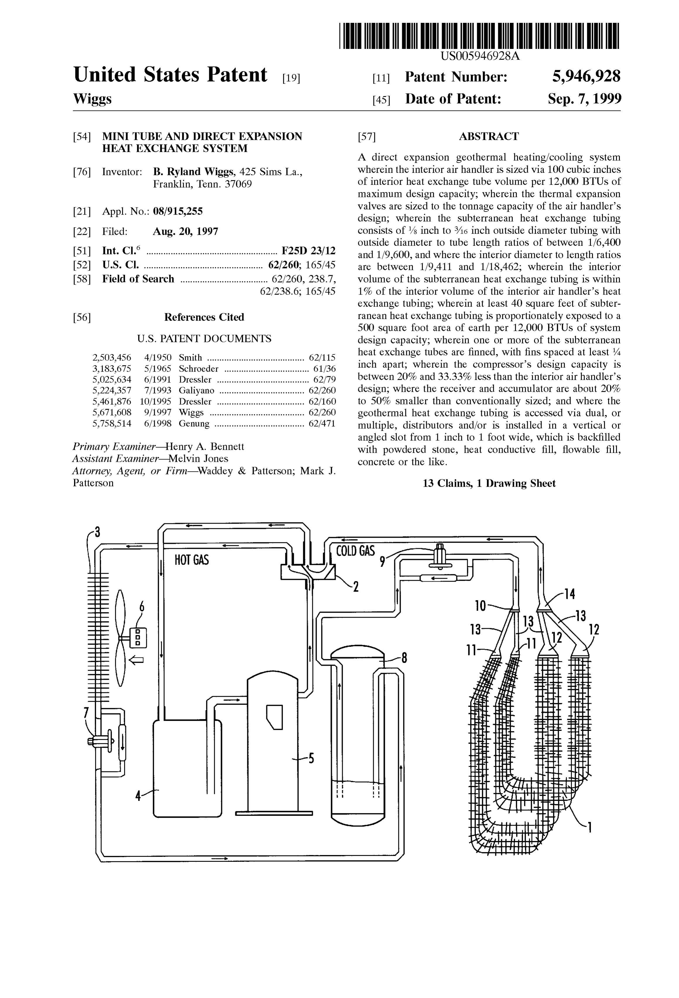
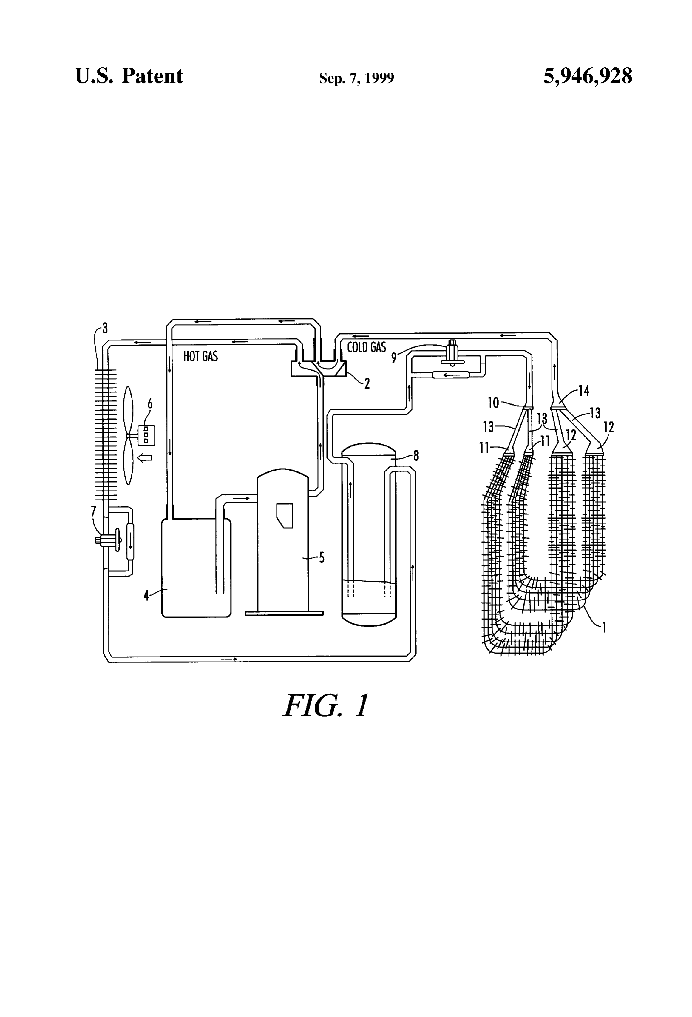
Fins on the ground heat transfer tubing may be spaced as heating mode, including ground heat eXchange tubes, inte little as /4 inch apart when the ground heat transfer tubing is rior air heat eXchange coils, a fan, thermal expansion valves, surrounded by a fine crushed stone or by a flowable fill, or a compressor, an accumulator, a receiver, a reversing valve, concrete, or cement, or the like, which will fill the void two liquid distributors, and two gas distributors. Various Spaces between the fins without leaving air gaps. controls, the thermostat, the electric power Source, and other Fins on ground heat transfer tubing installed in, and common items are not shown Since the design of Same is backfilled with, a Soil tending to clump, or clod, Such as a well know by those in the refrigeration trade. clay Soil, or the like, should be spaced at least Six inches DETAILED DESCRIPTION OF THE apart So as to help avoid unfilled pockets of air, which are PREFERRED EMBODIMENTS very poor heat conductors, and which inhibit the desired heat transfer into, or out of, the ground to the refrigerant circu The following detailed description is of the best presently lating within the heat transfer tubing. contemplated mode of carrying out the invention. The Ninth, the aforesaid problems encountered via conven description is not intended in a limiting Sense, and is made tional direct expansion Subterranean heat eXchange coils 15 Solely for the purpose of illustrating the general principals of congregating in one place at the liquid line distributor, and the invention. The various features and advantages of the in one place at the vapor line distributor, which are often in present invention may be more readily understood with relatively close proximity to one another due to the use of reference to the following detailed description taken in relatively equally lengthed line Sets, and which, when in conjunction with the accompanying drawings. close proximity at hot/cold temperature extremes, tend to Referring now to the drawings in detail, where like negate Some of the geothermal heat eXchange advantage, can numerals refer to like parts or elements, there is shown in be overcome via the use of dual or multiple distributors. FIG. 1 a simple version of a direct expansion geothermal A Single vapor line and a single liquid line, of equal heat pump System, operating in a heating mode. lengths, can Still be run from the interior equipment to the A refrigerant fluid (not shown) is evaporated into a gas in perimeter of the geothermal heat eXchange tube array. 25 finned ground heat eXchange tubing 1. The vaporized refrig Thereafter, a first set of distributors can transfer the refrig erant travels through a Second line set vapor (gas) distributor erant fluid to a Second Set of Smaller multiple lines, of 12 through multiple line Sets 13, through a first line Set vapor approximate equal length, which will convey the refrigerant (gas) distributor 14, through a single line Set, through a fluid to a second respective set of distributors, which will reversing valve 2, utilized for reversing the direction of the convey the hot/cold refrigerant fluid to additional, Smaller, refrigerant fluid through the ground heat eXchange tubing 1 multiple, but minimally congregating, geothermal heat and through the finned air heat eXchange tubing 3 when the eXchange tubing. It is presently well known that line Sets System is operating in a cooling mode, to an accumulator 4, should be insulated when in close proximity (within 10 feet which traps any liquid refrigerant fluid So as to help prevent to 15 feet) of one another, which practice should continue to any liquid from entering into the refrigerant gas compressor be followed.
35 5. The refrigerant fluid, in a cool gaseous State, exits the
Lastly, and tenth, the Subject invention teaches how to accumulator 4, and enters the refrigerant gas compressor 5, install a Safe, minimally invasive, low cost direct expansion where it is compressed into a hot gaseous, or vapor, State. ground coil configuration. This is accomplished via utiliza The hot refrigerant gaseous fluid thereafter travels tion of a small back-hoe, or a "Ditch Witch' minimal width through the reversing valve 2 to the finned air heat eXchange trencher, or the like, which excavates a slot in the ground to 40 tubing 3 where heat is removed from the hot refrigerant a typical depth of about 6 feet to 15 feet, with a slot width gaseous fluid and transferred to interior air via assistance between one inch and one foot. A matrix of direct expansion from an electric fan 6.
ground coils, Spaced Some pre-determined distance apart, The refrigerant fluid thereafter travels past one thermal depending on whether finned or unfinned, and depending on expansion valve (TX valve) 7, for use in cooling mode the width of the excavated slot in the earth, are lowered into 45 operation, through a receiver 8, through a heating mode the excavated slot, which is thereafter backfilled with pow thermal expansion valve (TX valve) 9, through the first line dered Stone, or cement, or concrete, or flowable fill, or the set liquid distributor 10, through multiple line sets 13, like. It would be best to pump a flowable fill mixture in from through a Second line Set liquid distributor 11, into the the bottom and let it fill the excavated slot via rising to the Subterranean finned ground heat eXchange tubing 1, where top, So as to eliminate as many potential non-heat 50 the entering cooled and condensed refrigerant fluid absorbs conductive air gaps as possible. heat from the ground, is vaporized, and exits through the The one inch to one foot width of the excavated slot is Second line Set vapor distributor 12, where the proceSS is Small enough to prevent a workman from accidentally repeated until enough heat is Supplied to the interior Struc falling in and Subjecting himself to potential injury or death ture (not shown) to satisfy the interior thermostat (not via a Subsequent unforeseen cave in of the excavated area. 55 shown), which disengages System operation. Further, the use of a small width excavator is minimally I claim:
invasive, and will provide a means for a relatively quick and 1. A direct expansion geothermal heat eXchange System inexpensive ground coil installation. where the Subterranean heat eXchange tubing consists of BRIEF DESCRIPTION OF THE DRAWINGS tubing with an outside diameter of between /s inch outside 60 diameter and 3/16 inch outside diameter, where the outside
For the purpose of illustrating the invention, there are diameter to individual tube length ratios are between 1/6,400 shown in the drawings forms which are presently preferred; and 1/9,600, and where the interior diameter to individual it being understood, however, that the invention is not tube length ratios are between 1/9,411 and 1/18,462. limited to the precise arrangements and instrumentality's 2. The direct expansion geothermal heat eXchange System shown. 65 of claim 1, further comprising: FIG. 1 is an isometric view of a simple version of a direct an air handler constructed with conventional air handler expansion geothermal heat pump System, operating in a finned tubing in fluid connection with Said Subterranean
Page 7
heat eXchange tubing, wherein Said air handler finned 10. The direct expansion geothermal heat eXchange SyS tubing has a combined interior volume of 100 cubic tem of claim 1, further comprising: inches per 12,000 BTUs of the greater of the system's a tubing containment slot, wherein Said slot is between heating or cooling design capacity in tonnage. one inch and one foot wide and extends up to a depth 3. The direct expansion geothermal heat eXchange System of 25 feet;
of claim 2, further comprising:
a Self-adjusting thermal expansion valve in fluid connec Said Subterranean heat eXchange tubing placed into Said tion with Said Subterranean heat eXchange tubing, slot, wherein Said tubing is Selected from a group wherein Said valve is sized to match the greater of the containing both finned and un-finned tubings, and System's heating or cooling design capacity in tonnage. a backfill material to fill in Said slot around Said tubing, 4. The direct expansion geothermal heat eXchange System wherein Said backfill material is Selected from a group of claim 1, further comprising: containing powdered Stone, fine Stone, powdered metal, interior air handler heat eXchange tubing in fluid connec fine metal, heat conductive Sand, heat conductive Soil, tion with Said Subterranean heat eXchange tubing, heat conductive silt, cement, concrete, flowable fill,
wherein the interior Volume of Said Subterranean heat heat conductive gel, heat conductive grout, heat con eXchange tubing is within one percent of the interior ductive fluid, and other heat conductive material in fine, Volume of Said interior air handler heat eXchange powdered, and granular consistencies. tubing. 11. The direct expansion geothermal heat eXchange SyS 5. The direct expansion geothermal heat eXchange System tem of claim 1, further comprising: of claim 4, wherein: at least two lengths of approximately equal length liquid the exterior Surface area of Said Subterranean heat and vapor line Sets constructed from Said Subterranean eXchange tubing is greater than 40 Square feet of heat eXchange ground tubing, and exterior surface area per 12,000 BTUs of the greater of at least two liquid and vapor distributors connected to Said the System's heating or cooling design capacity in 25 Subterranean heat eXchange ground tubing. tonnage. 12. A geothermal heat eXchange System wherein the 6. The direct expansion geothermal heat eXchange System compressor's BTU design capacity is between 20% and of claim 5, wherein: 33.33% less than the interior air handler's BTU design Said exterior Surface area is exposed to 500 Square feet of capacity for any given heating or cooling load. Subterranean ground surface per 12,000 BTUs of the 13. A direct expansion geothermal heat eXchange System, design capacity. comprising:
7. The direct expansion geothermal heat eXchange System Subterranean heat eXchange tubing, of claim 1, further comprising: an air handler constructed with conventional air handler fins on Said Subterranean heat eXchange tubing, wherein finned tubing in fluid connection with Said Subterranean Said fins are spaced a minimum of one quarter inch 35 heat eXchange tubing, wherein Said air handler finned apart. tubing has a combined interior volume of 100 cubic 8. The direct expansion geothermal heat eXchange System inches per 12,000 BTUs of the greater of the system's of claim 1, further comprising: heating or cooling design capacity in tonnage; a receiver in fluid connection with Said Subterranean heat a Self-adjusting thermal expansion valve in fluid connec eXchange tubing, wherein Said receiver has a, maxi 40 tion with Said Subterranean heat eXchange tubing, mum storage capacity of 18% of the total volume of wherein Said valve is sized to match the greater of the System refrigerant. System's heating or cooling design capacity in tonnage; 9. The direct expansion geothermal heat eXchange System and of claim 1, further comprising: 45 an accumulator in fluid connection with Said Subterranean an accumulator in fluid connection with Said Subterranean heat eXchange tubing, wherein Said accumulator has a heat eXchange tubing, and maximum design capacity equal to the design capacity and air handler wherein Said accumulator has a maximum of Said air handler.
design capacity equal to the design capacity of Said air handler.
Provenance
- Collection
- Cited prior art
- Original PDF
- patentimages.storage.googleapis.com →
- Filed
- 1997-08-20
- Pages
- 7
- Method
- pdftotext (the PDF's own text layer) + pdftoppm 300dpi page scans
- Source
- Google Patents bibliographic record
- Granted
- 1999-09-07
- Inventors
- B. Ryland Wiggs
- Transcribed from
- patentimages.storage.googleapis.com →