patent · US5914416
Device for separating solid or liquid particles from a stream of gas
22 June 1999
Page 1 — bibliographic record
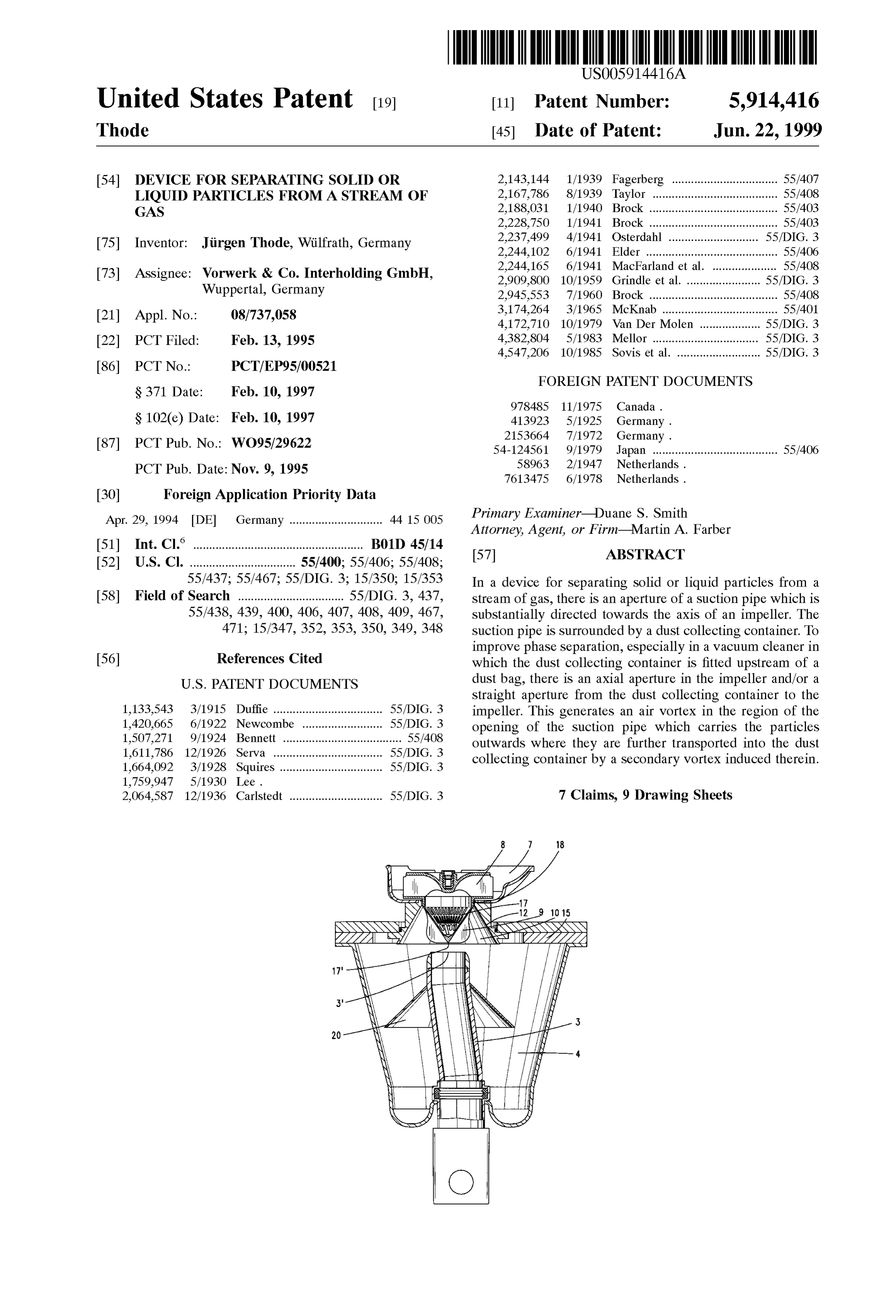
United States Patent (19) 11 Patent Number: 5,914,416 Thode (45) Date of Patent: Jun. 22, 1999 54) DEVICE FOR SEPARATING SOLID OR 2,143,144 1/1939 Fagerberg ................................. 55/407 LIQUID PARTICLES FROM ASTREAM OF 2,167,786 8/1939 Taylor ... ... 55/408 GAS 2,188,031 1/1940 Brock .. ... 55/403 2.228,750 1/1941 Brock ...... ... 55/403 2,237,499 4/1941 Osterdahl ............................ 55/DIG. 3 75 Inventor: Jirgen Thode, Wilfrath, Germany 2,244,102 6/1941 Elder ......................................... 55/406 2,244,165 6/1941 MacFarland et al. .................... 55/408 73 Assignee: Worwerk & Co. Interholding GmbH, 2.909,800 10/1959 Grindle et al....... . . 55/DIG. 3 Wuppertal, Germany 2.945,553 7/1960 Brock .......... ... 55/408 3,174.264 3/1965 McKnab ......... ... 55/401 21 Appl. No.: 08/737,058 4,172,710 10/1979 Van Der Molen .. ... 55/DIG. 3 22 PCT Filed: Feb. 13, 1995 4,382,804 5/1983 Mellor ................................. 55/DIG. 3 4,547,206 10/1985 Sovis et al. .......................... 55/DIG. 3
FOREIGN PATENT DOCUMENTS
S 102(e) Date: Feb. 10, 1997 413923 5/1925 Germany.
87 PCT Pub. No.: WO95/29622 54-124561 9/1979 Japan ....................................... 55/406 PCT Pub. Date: NOW. 9, 1995 58963 2/1947 Netherlands.
30 Foreign Application Priority Data
Apr. 29, 1994 DE Germany ............................. 44 15 005 Primary Examiner Duane S. Smith
Attorney, Agent, or Firm Martin A. Farber (51) Int. Cl." ..................................................... B01D 45/14 57 ABSTRACT 52 U.S. Cl. ................................. 55/400; 55/406; 55/408;
55/437; 55/467; 55/DIG. 3; 15/350; 15/353 In a device for Separating Solid or liquid particles from a 58 Field of Search ................................. 55/DIG. 3, 437, Stream of gas, there is an aperture of a Suction pipe which is 55/438, 439, 400, 406, 407,408, 409, 467, substantially directed towards the axis of an impeller. The 471; 15/347, 352, 353, 350, 349,348 Suction pipe is Surrounded by a dust collecting container. To improve phase Separation, especially in a vacuum cleaner in 56 References Cited which the dust collecting container is fitted upstream of a
Straight aperture from the dust collecting container to the 1,133,543 3/1915 Duffie .................................. 55/DIG. 3 impeller. This generates an air Vortex in the region of the 1,420,665 6/1922 Newcombe .. ... 55/DIG. 3 opening of the Suction pipe which carries the particles 1,507,271 9/1924 Bennett ..................................... 55/408 outwards where they are further transported into the dust 1,611,786 12/1926 Serva ....... ... 55/DIG. 3 collecting container by a Secondary Vortex induced therein. 1,664,092 3/1928 Squires ................................ 55/DIG. 3
2,064,587 12/1936 Carlstedt ............................. 55/DIG. 3 7 Claims, 9 Drawing Sheets
Page 2
Drawing sheet — no readable text.
Page 3
Drawing sheet — no readable text.
Page 4
Drawing sheet — no readable text.
Page 5
Drawing sheet — no readable text.
Page 6
Drawing sheet — no readable text.
Page 7
Drawing sheet — no readable text.
Page 8
Drawing sheet — no readable text.
Page 9
Drawing sheet — no readable text.
Page 10
Drawing sheet — no readable text.
Page 11
DEVICE FOR SEPARATING SOLID OR aperture width and the bar height are, with regard to the LIQUID PARTICLES FROM ASTREAM OF rotational Speed and to the maximum speed of the gas, GAS matched to one another in Such a way that the particles passing through the apertures when the Sieve is rotating are
FIELD AND BACKGROUND OF THE always met by the bar and are thus spun out of the sieve. The INVENTION cone-shaped Sieve form is especially Suitable for this mecha The invention relates to a device for Separating Solid or nism. Another development of the invention provides that liquid particles from a stream of gas, in particular a vacuum the Suction tube, in the region of the dust collecting cleaner. container, is Surrounded by a funnel-shaped Screen. By this A device of this kind is known from OS 2153 664. Which means there is minimised the formation of the induced comprises a vacuum cleaner, in which dust-laden air is Secondary Vortex in the region of the base of the dust Sucked through a Suction tube by a fan. Connected upstream collecting container.
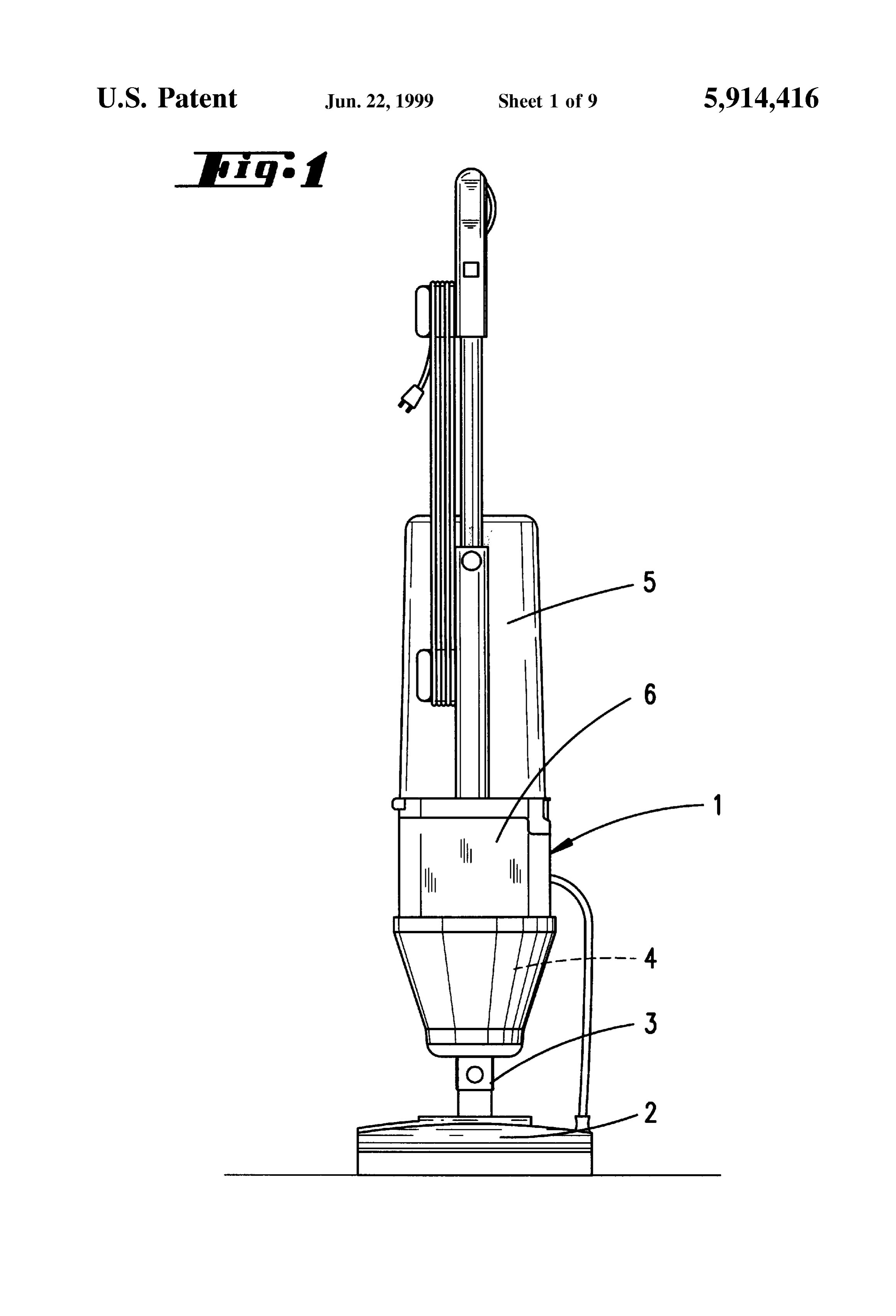
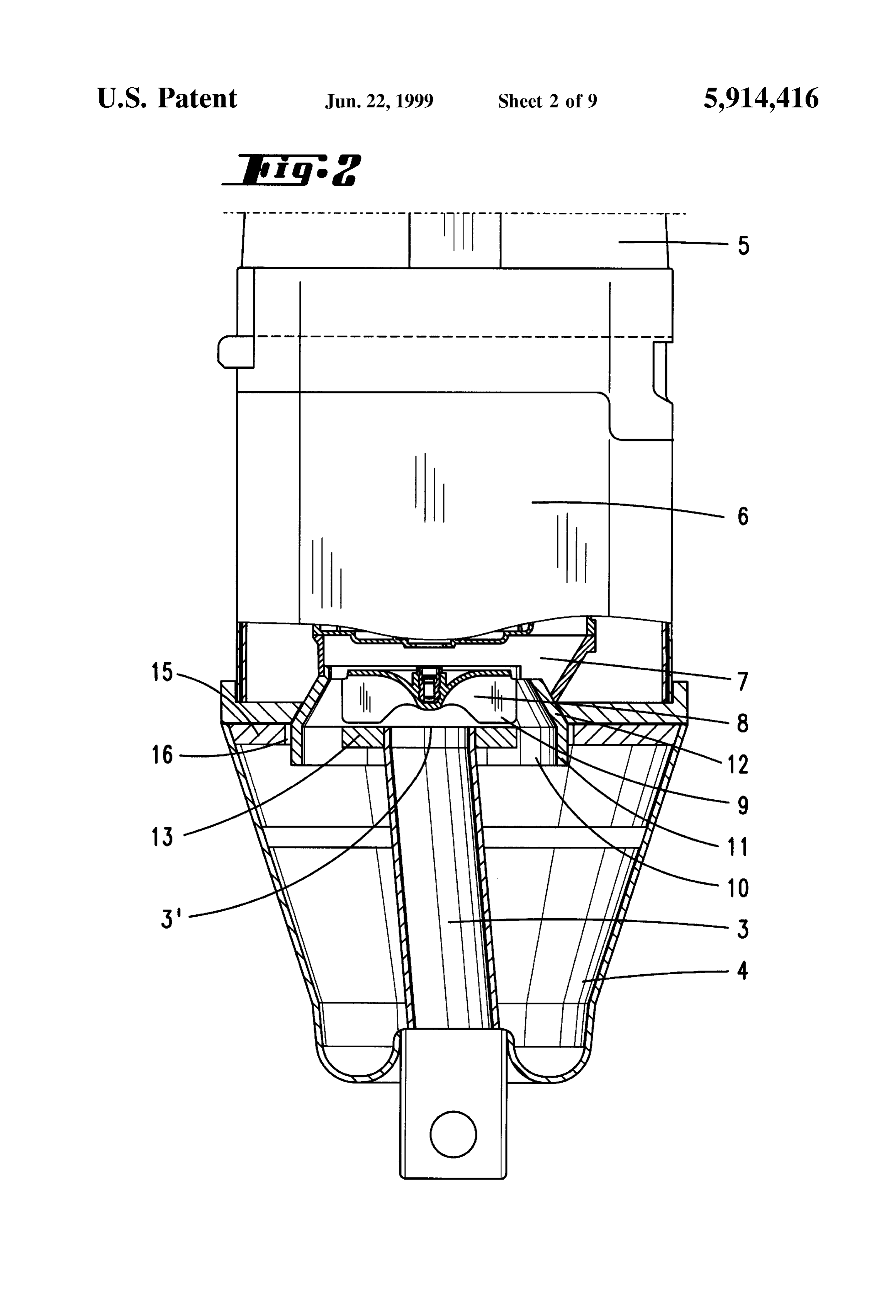
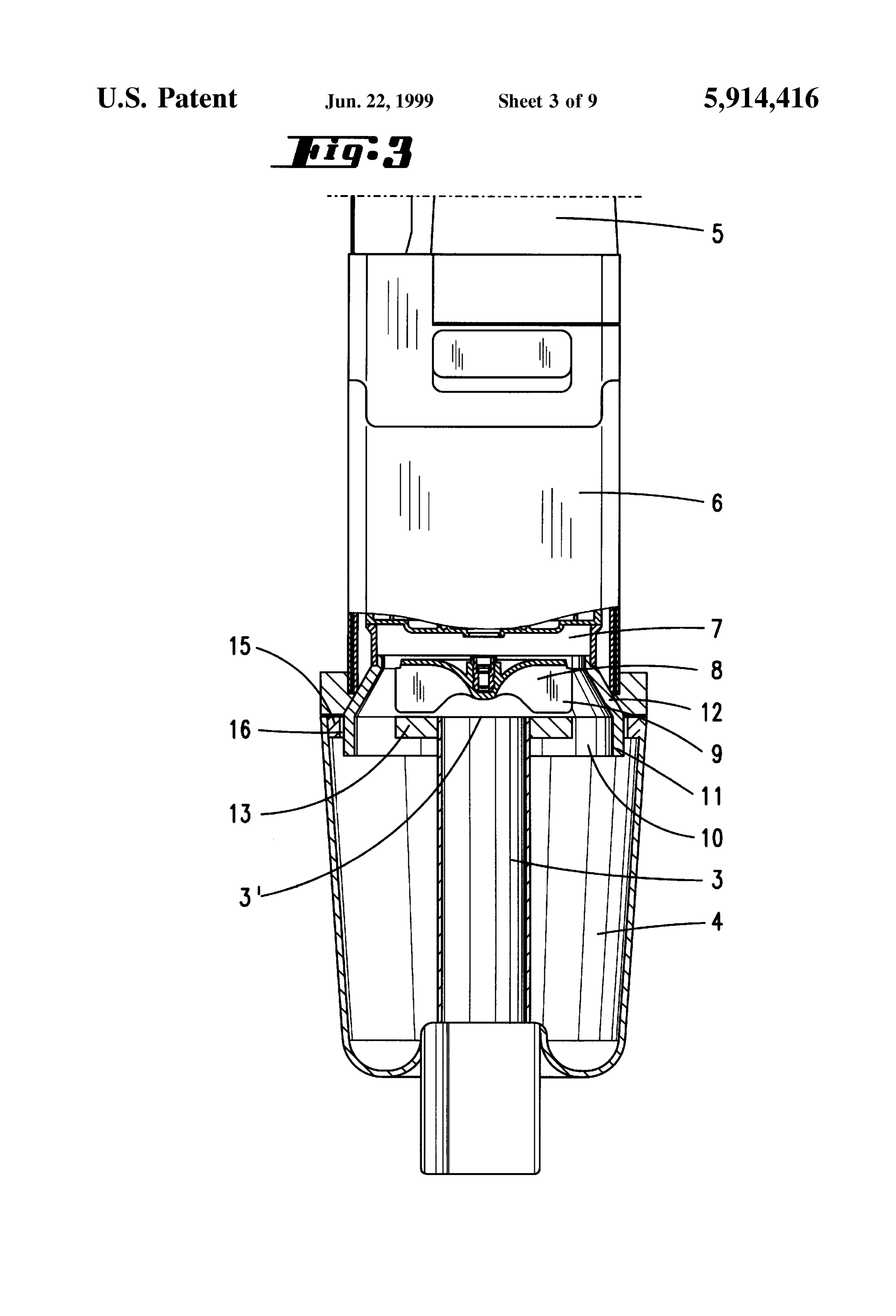
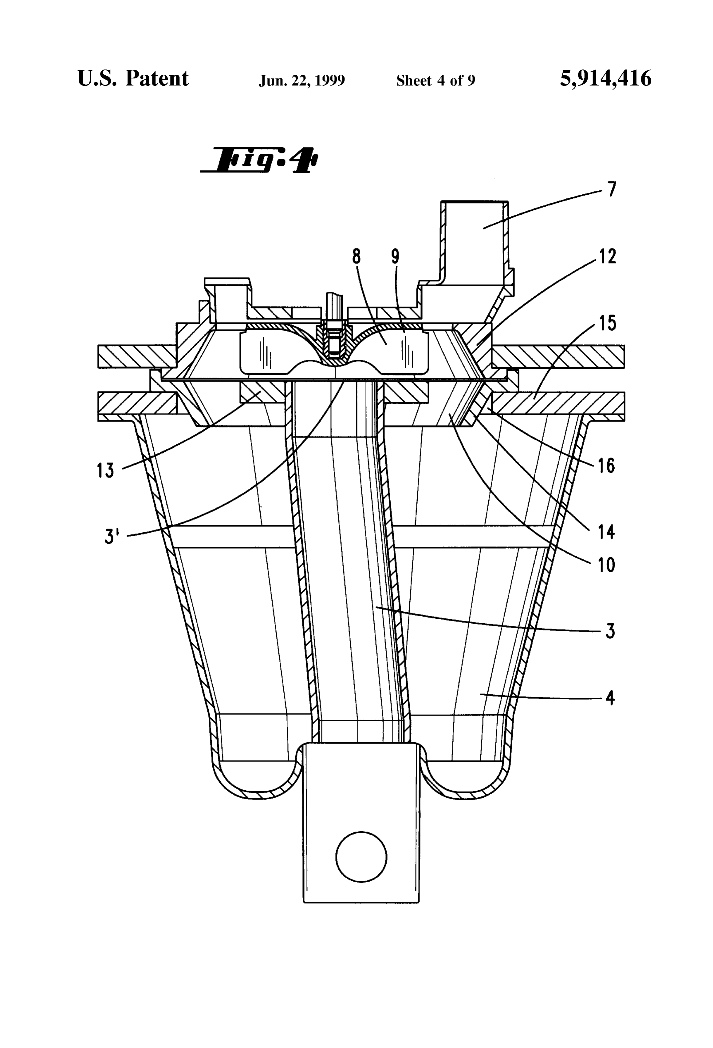
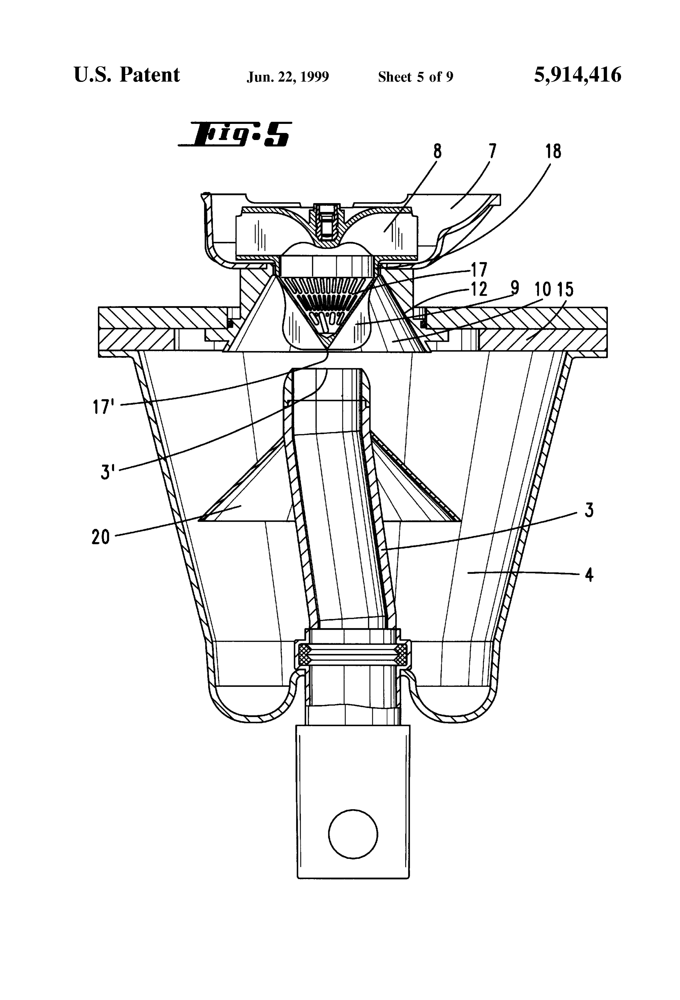
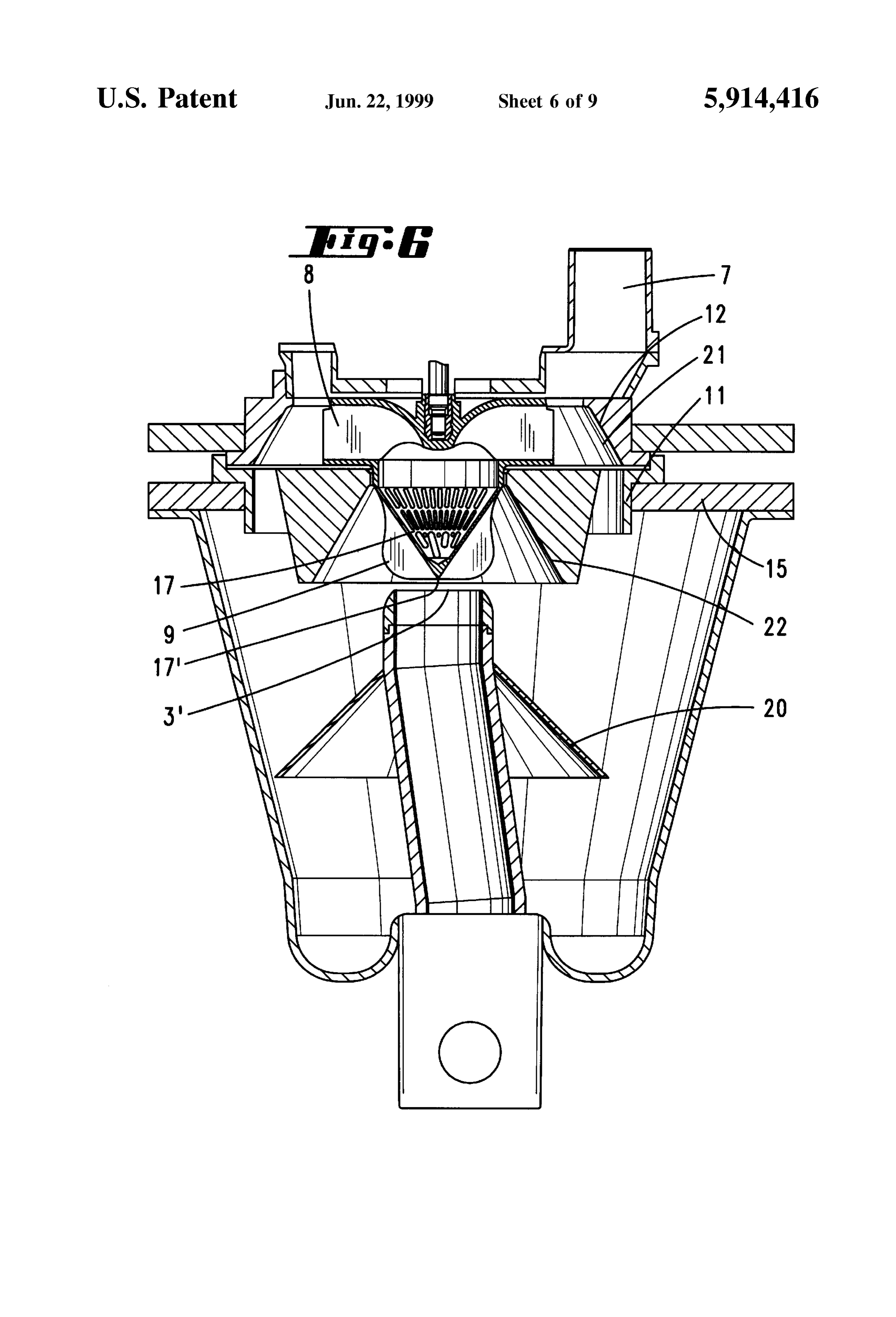
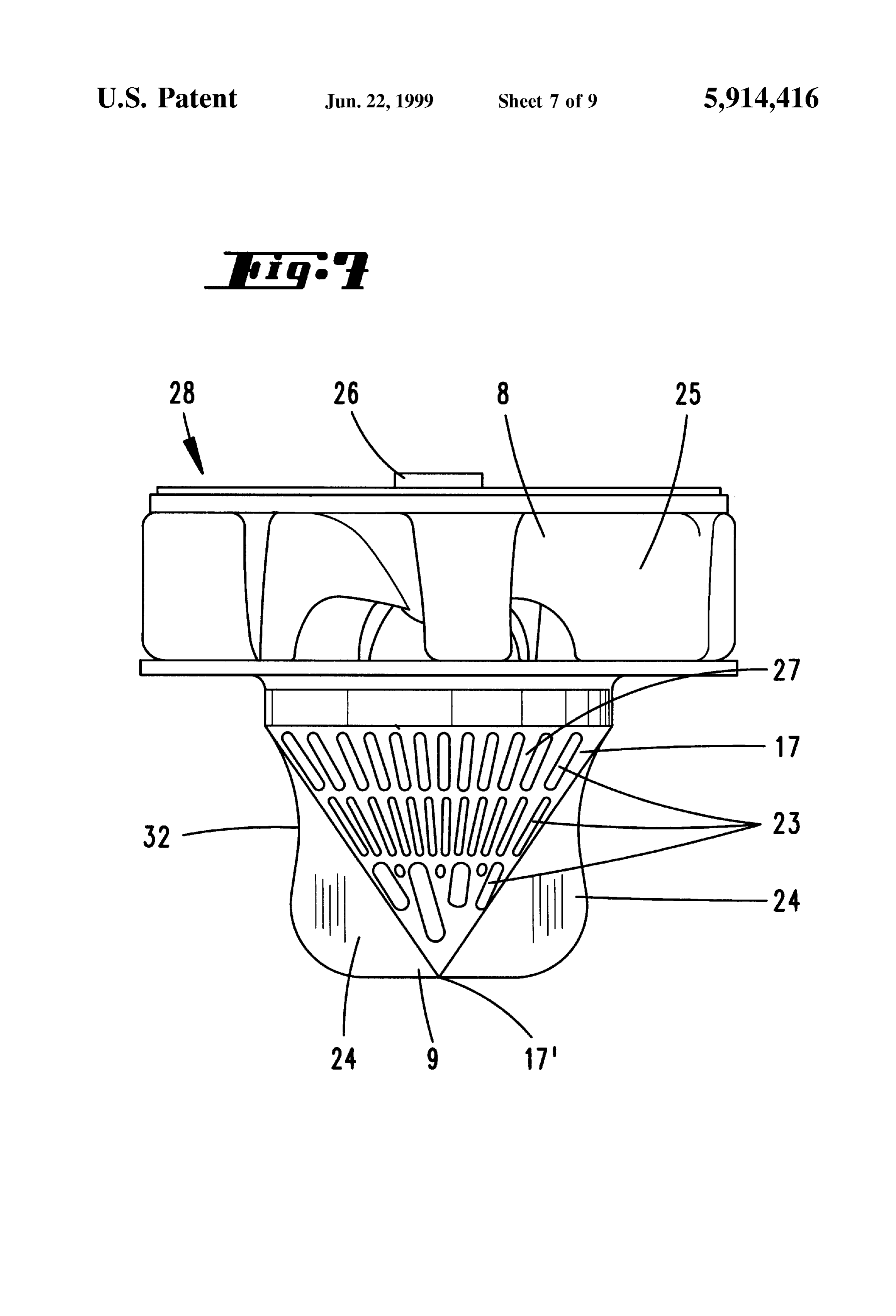
of the fan is an impeller, towards whose axis the opening of BRIEF DESCRIPTION OF THE DRAWINGS the Suction tube is directed. Upstream of the impeller, there 15 is located a dust collecting container Surrounding the Suction With the above and other objects and advantages in view, tube. By means of a Screw-thread shaped channel, the dust the present invention will become more clearly understood collecting container is linked to the impeller. in connection with the detailed description of preferred In the known Solution, it has proven that the particle embodiments, when considered with the accompanying Separation from the Stream of gas is only incomplete. drawings, of which:
SUMMARY OF THE INVENTION FIG. 1 shows a vacuum cleaner according to the invention,
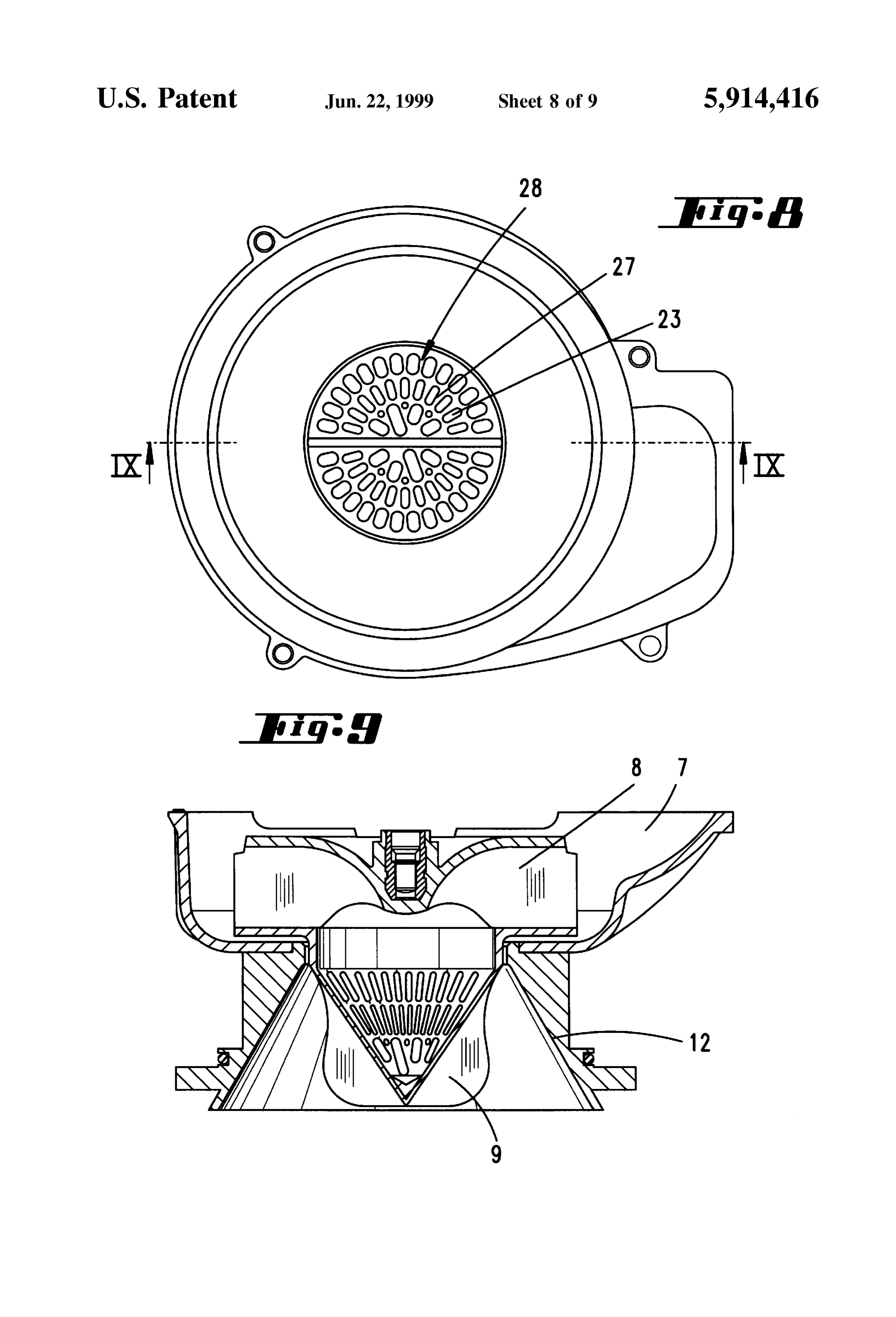
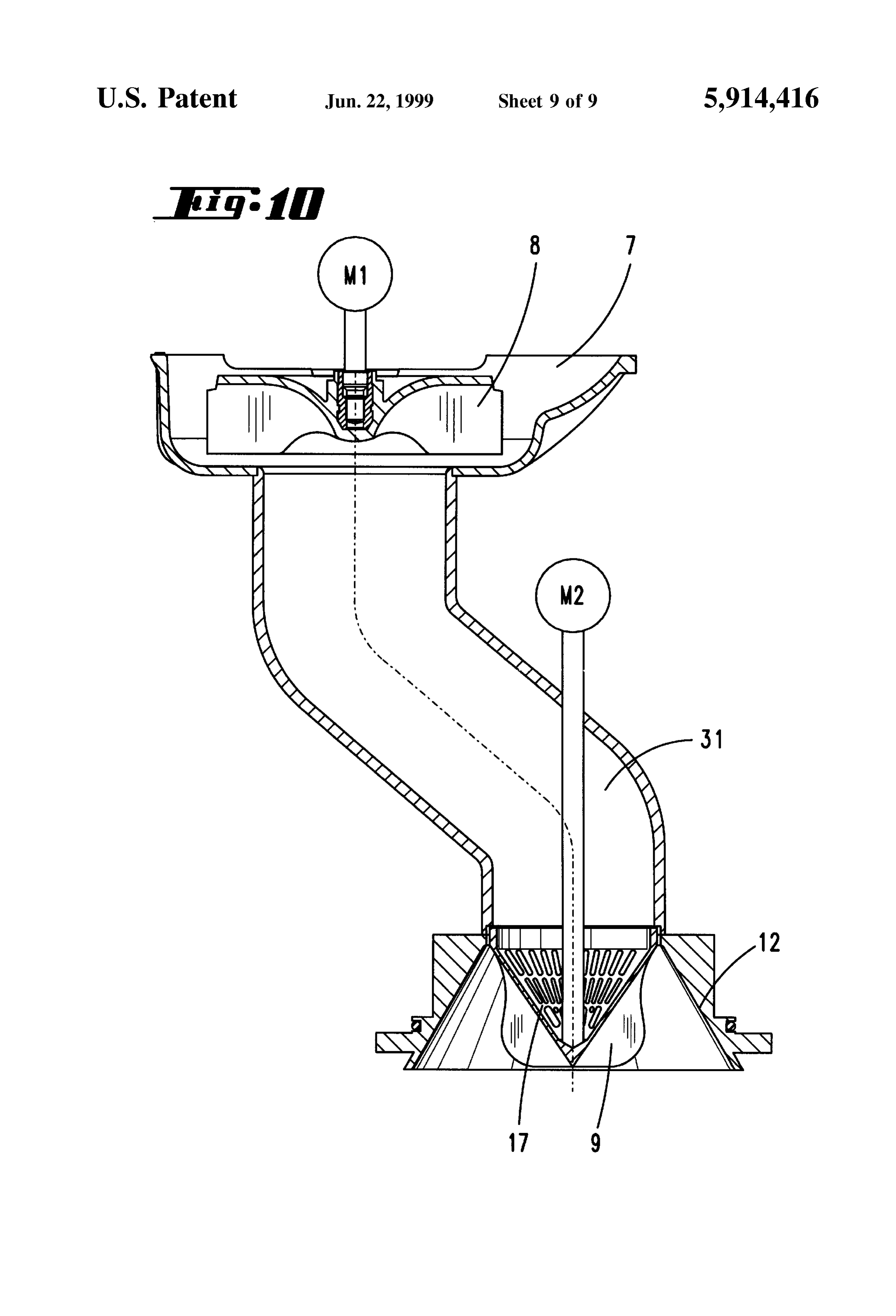
The invention is therefore based on the problem of FIG. 2 shows a section through a first embodiment, improving the phase Separation in a device of this kind. FIG.3 shows a section according to the first embodiment, AS a result of the development, according to the 25 turned through 90, invention, of the known device, there is generated, in the FIG. 4 shows a Section through a Second embodiment, region of the opening of the Suction tube, an air Vortex which transports the particles outwards. There, the particles are to FIG. 5 shows a section through a third embodiment, be further transported into the dust collecting container by a FIG. 6 shows a section through a fourth embodiment, Secondary Vortex induced in the dust collecting container. It FIG. 7 shows a sieve-blade fan wheel according to is essential in this connection, that the Solid or liquid embodiments three, four and five, particles to be separated are transported out of the Stream of FIG. 8 shows the plan view onto the impeller of a fifth gas. It may be provided, in this connection, that the impeller embodiment, is formed by the fan wheel. Because of the straight-line FIG. 9 shows a section through a sieve-blade fan wheel opening of the dust collecting container, extending through 35 according to the fifth embodiment, corresponding to the line in the direction of the impeller, the particles, accelerated by IX-IX, and impinging upon the impeller, are seized by the Secondary FIG. 10 shows a sixth embodiment of the invention. Vortex and transported out of the Stream of gas, So that the particles may deposit in the dust collecting container. To DETAILED DESCRIPTION OF THE intensify the development of Secondary Vortices, the ratio of 40 PREFERRED EMBODIMENTS dust container diameter and impeller diameter should pref erably assume values greater than 2. A development of the The device according to the invention, for the Separation invention provides that the impeller is located, in the direc of phases, i.e. Solid or liquid particles from a stream of gas, tion of flow, before the fan wheel. By this means, the phase is preferably used in a vacuum cleaner, as is represented Separation takes place before the fan wheel, So that the fan 45 here, for example, in FIG. 1. The vacuum cleaner 1 has a wheel is not impinged upon by particles. In this motor housing 6, in which there is provided an electric arrangement, it proves advantageous for the Stream of gas to motor, which operates a fan wheel 8, by which the suction pass in axial direction through the impeller. The particles air is Sucked through a Suction nozzle 2 and a Suction tube accelerated tangentially on impinging upon the blade Sur 3 connected to the nozzle. An impeller 9 provided in the faces then move in a Substantially Stationary Vortex about 50 Vacuum cleaner 1 is intended, in this connection, to Separate the impeller axis and, as a result of the centrifugal force, the Solid or liquid particles from the Stream of gas. The air reach the edge of a impeller chamber, from which, as a result thus precleaned is then transported by the fan wheel 8 into of the gravitational force or of the induced Secondary Vortex, the dust bag now acting as fine filter 5. they are transported into the dust collecting container. The The Separation of the Solid and liquid particles from the impeller chamber has, preferably, a funnel-shaped form and 55 Stream of gas is effected, preferably, at a rotational Speed of ends cone-shaped in the direction of Suction. The impeller is 20,000 to 35,000 revolutions per minute. Especially by the preferably two-bladed. The blades may be disposed, accord use of a cone-shaped Sieve 17, the particle size which ing to a preferred development, in the region of the tip of a deposits in the dust collecting container 4 may be reduced to cone-shaped Sieve, the cone widening in the direction of the the size of 10 um. This has the advantage that the dust bag Stream of gas. The rotational Speed is to amount to from 60 5 as good as never needs to be emptied and that the dust bag 10,000 revolutions per minute. By this means, there is 5 may be formed to be very small in its dimensions. provided an effective impulse transfer to the particles from Moreover, the filter cloth used for the dust bag may be the blades or from the bars of the sieve. matched to the particle fraction up to the size of 10 um, So A compact Structural Shape is achieved when the impeller, that use may be made of a high-energy filter System, the Sieve and the fan wheel are joined to one another as a 65 advantageous with regard to cost. The device is Suitable for material unit. The cone-shaped Sieve has apertures which are the Separation of Solid particles, but also for the Sucking up interrupted in the circumferential direction by bars. The of liquid. The liquid droplets present in the Stream of gas are,
Page 12
in the same way as dust particles, accelerated tangentially by on the effective height of the bar in the direction of the the impeller and transported out of the Stream of air. Stream of gas. The dimensioning of aperture width and bar The first embodiment represented in FIGS. 2 and 3 has a height is chosen as a function of the maximum air flow speed dust collecting container 4, which Surrounds the Suction tube through the opening and the rotational Speed of the Sieve in 3. The opening 3' of the Suction tube 3 is directed towards Such a way that the dust particles, on passage through the the axis of an impeller 9. In this embodiment, the impeller aperture, are met by the bar 27. By this means, there is is formed by the fan wheel 8. The impeller 9 is surrounded, guaranteed an optimal Separation of the phases. All particles in this connection, by a funnel-shaped sleeve 12, the tip of not already met by the blade 24 of the impeller 9 are then, the funnel pointing, here, in the direction of the Stream of on entry into the Sieve, tangentially accelerated, So that they gas. On the funnel opening Side, a cylindrical sleeve region are spun transversely out of the Suction flow which extends 11 is connected to the sleeve surface 12. The cylindrical Substantially in the axial direction and then deposit in the sleeve region 11 Overlaps, in this connection, the opening dust collecting container 4. The radius of the blade 24 is, in region of the Suction tube 3. A Screen 13 is disposed around this connection, at least as great as, preferably slightly the opening 3' of the suction tube 3, which screen is greater than, the radius of the circular opening 3' of the cylindrical and has the same diameter as the impeller 9. By 15 Suction tube 3. In the same way, the greatest diameter of the this means, it is achieved that the impeller Sucks in only air Sieve 17 is Somewhat larger than the opening 3'. out of the Suction tube 3. As is to be noted in particular from FIG. 7, the impeller The dust collecting container 4 is otherwise closed on all 9 forms, together with the sieve 17 and the fan wheel 8, a Sides. Only in the region of its cover 15 is there an opening Single material unit, namely the Sieve-blade fan-wheel 28. 16, into which the aforementioned cylindrical cover pen This sieve-blade fan-wheel 28 has a drive coupling 26 for etrates. The funnel-shaped sleeve 12 extends approximately the shaft of the electric motor. It also has a multiplicity of fan over the entire impeller region. At its Smaller-diametered blades 25.
Side, the Sleeve 12 has a circular slit, which opens into an In the embodiment according to FIGS. 5 to 10, there may exit air channel 7. The exit air channel 7 conducts the air past 25 be seen a cylindrical portion 18 in the intermediate region the motor into the dust bag 5. between the downstream-located fan wheel 8 and the conical As a result of the rotational movement of the impeller 9 sieve 17 of the sieve-blade fan-wheel 28, which cylindrical about its axis, the air is accelerated in the radial direction. portion 18 is encompassed by the Smallest-diametered Because of the otherwise all-sided closure of the dust region of the dust collecting container opening 10 which collecting container 4, the air Sucked in by the fan wheel 8 terminates in a funnel-shape. The wall is formed by the may escape only through the Slits on the funnel-opening sleeve 12. By this arrangement, it is assured that all the air side, into the exit air channel 7. About the impeller 9, there is sucked through the conical sieve 17 by the fan wheel 8. forms an air Vortex which, as a result of the sloping wall of This means that, as a result of the impinging, effected in the the sleeve 12, extends out into the region of the sleeve 11. circumferential direction, either of the bars 27 or of the In this Vortex, the Solid or liquid particles Separate in the 35 blades 24 on the dust particles, these dust particles are radial direction, that is into the region of the Screen 13. AS transported transversely out of the Stream of gas into a a result of the Straight-line opening 10 of the dust collecting Surrounding gas Vortex, from which they fall into the dust container 4 directed towards the impeller 9, there is induced, collecting container 4.
at least in the upper region of the dust collecting container In the embodiment according to FIG. 6, it is to be seen that 4, a Secondary Vortex, which transports the dust particles 40 a frustoconically shaped sleeve 22, which Surrounds the into the dust collecting container 4. The Screen 13 ensures conical Sieve 17, penetrates into the dust collecting container that the impeller 9 itself does not disturb the induced 4, through the opening of the cover 15 of the dust collecting Secondary Vortex. container 4. An additional, cylindrical-shaped sleeve 11 The second embodiment represented in FIG. 4 differs Surrounding the sleeve 22 is connected, by means of an from the first embodiment substantially in that the straight 45 auxiliary air channel 21, to the fan chamber, which has a line opening 10 of the dust collecting container 4 is Sur funnel-shaped wall 12. Between the opening plane of the rounded at the edge by a funnel-shaped sleeve 14. The opening of the sleeve 22 and the Suction-tube opening 3", largest diameter of the sleeve 14 adjoins the largest diameter there is a small space. The tip 17 of the sieve 17 lies in the of the funnel-shaped sleeve 12. Here also the air flows into opening plane of the sleeve 22, and is thus spaced apart by an exit air channel 7. 50 the same amount from the Suction opening 3'. In the embodiments three to six, the fan wheel 8 is not the In the sieve-blade fan-wheel 28 (see FIG. 7), there are same as the impeller 9. The fan wheel 8 is, on the contrary, provided two oppositely disposed blades 24, whose lower located, in the direction of flow, after the impeller 9. The of edges run into the tip 17 of the conical sieve 17. The corners impeller 9 also has such a form that the air flow can pass the blades 24 are rounded and the blades have an through the air blades substantially in the axial direction. For 55 arc-shaped reduction in area 32. The Vanes 24 merge this purpose, there are provided Sieve-type apertures 23, smoothly into the largest-diametered base of the sieve. The which are associated with a cone-shaped sieve 17. The blades 24 extend from these substantially parallel to the cone vertex angle of the cone should preferably amount to envelope surface of the sieve 17. By this means, it is between 40 and 140, in order to achieve an especially good guaranteed that the apertures 23 and the bars 27 lie at the separating effect. The vertex 17" of the sieve 17 points, in 60 Same height as the blades 24.
this connection, towards the opening 3' of the Suction tube In the embodiments according to FIG. 5 and FIG. 6, there 3. Onto the cone envelope Surface, there are moulded two is further provided a funnel-shaped screen 20, which Sur oppositely located blades 24, which form the impeller 9. On rounds the Suction tube 3. The largest-diametered region of the cone envelope surface of the sieve 17, there are provided the Screen 20 points, in this connection, in the direction of three rows of apertures 23, which are each Separated by bars 65 the base of the dust collecting container 4. 27. The width of the apertures 23 is dependent on the radial In a vacuum cleaner of this type, air impinges axially position of the respective aperture. The width depends also upon a centrifugal wheel, by which the air is guided radially
Page 13
S 6 outwards, So that the larger dust particles are spun against Separated dirt particles are conducted by the correspond the inner Side of a guiding Surface Surrounding the centrifu ingly formed inner Side of the Separating Space into the dust gal wheel. After that, the air, now laden only with fine dust collecting container 4. This air freed of dirt then flows particles, is diverted radially inwards into a drum located onwards axially into the blower unit 8. Dirt-laden air can behind the centrifugal wheel, which drum is smaller in also be understood to mean a water-air mixture, the water diameter, co-rotating, cylindrical, and provided with aper droplets being then Separated correspondingly from the air. tures. In that the drum is provided with a relatively large In the embodiment represented in FIG. 10, there is shown, number of apertures, which form Small blades, even the fine as well as the motor M2, which drives the separating unit 9, dust particles may be spun, by the better transmission of the 17, an additional motor M1, which operates the fan wheel 8. rotational movement to the air, outwards against the inner The fan wheel 8 and the separating unit 9, 17 are connected Side of a guiding Surface Surrounding the cylindrical drum. to one another by a flow channel 31. After flowing through the drum, the air is diverted again in I claim:
the axial direction and blown out by the motor into the 1. A device for the Separation of Solid or liquid particles environment. Dust which reaches downstream-located filter from a stream of gas, comprising a rotatable fan wheel and bags may, in this connection, with increasing filling of the 15 an impeller rotatable in conjunction with rotation of the fan filter, reduce the Suction capacity of the device. In order to wheel, the impeller being located upstream of the fan wheel realize a phase Separation within the Smallest possible in the direction of flow and being configured for urging the Structural Space, with the shortest possible flow path, as far particles in a direction transverse to the Stream of gas prior as possible without change in the direction of the flow and to passage of the gas through the fan wheel, wherein the with better flow efficiency, it is provided, according to the device further comprises a conical Screen which adjoins the invention, that there is provided, in a vacuum cleaner, a dust impeller in the direction of flow of the Stream of gas, and a collecting container, a Space for a blower unit 8 and a Space particle receiving region encircling the impeller for receiv for the air exit 7. The Suction tube 3 is in connection, on the ing particles deflected from the gas Stream by the impeller. one side, with a cleaning nozzle 2 and, on the other Side, 2. The device according to claim 1, wherein the impeller with the dust collecting container 4. The dirt-laden air is 25 comprises Said conical Screen and a plurality of Vanes guided, in this connection, by the Suction tube 3 in Such a protruding radially from Said conical Surface. way that it impinges centrally on a separating unit 28 (the 3. A device according to claim 1, further comprising an impeller 9), which is located in a separating space. The element encircling Said impeller for forming a Space Separating unit 28 comprises a cone-shaped hollow body, between the conical Screen and the encircling element, the which is provided with the apertures 23 which are aligned in Space terminating in the shape of a funnel in the direction of the direction of flow of the air. On the cone-shaped hollow flow of the gas Stream, Said encircling element having a body 17, there are mounted a number of straight, radial conical Surface positioned for deflecting the particles into blades 24. The separating unit is either fixedly mounted on Said particle receiving region.
the fan wheel 8, which is driven by a motor shaft 26, or is 4. A device according to claim 1, wherein the impeller is connected to the fan wheel by a further suction tube (FIG. 35 a two-bladed impeller.
10) 31 and is then driven by a separate motor M2. Dirt 5. A device according to claim 1, wherein the impeller, the particles which are Separated by the Separating unit 28 are Screen, and the fan wheel are joined to one another as a diverted by the inner wall Surface 12 of the Separating Space, unitary Structure.
which is in connection with the dust collecting container 4, 6. A device according to claim 1, wherein the Screen into this dust collecting container 4. The air thus cleaned 40 comprises bars defining apertures, and the apertures of the then flows onwards to the fan wheel 8, and from there into Screen in the circumferential direction and the height of the the air exit 7. bars of the Screen interrupting the aperture are matched to By the arrangement according to the invention, it is one another in Such a way that particles entering into the achieved that the dirt-laden air impinges, through the Suction apertures upon rotation of the apertures at maximum Suction tube 3, axially upon the separating unit 9, 17, through which 45 Speed are impinged upon by the bars during their passage it then also axially emerges, while the coarse dirt is spun, by through the apertures.
the straight blades 24 and the fine dirt by the small blade 7. A device according to claim 1, further comprising a wheel formed by the apertures 23 in the cone-shaped hollow Suction tube guiding the Stream toward the impeller, and a body 17, radially outwards against the inner side of the Substantially funnel-shaped Screen disposed upstream of the Separating Space. There is achieved, by these many Small 50 impeller, and projecting from the Suction tube into a dust apertures 23, a better transfer of the rotational movement to collecting container of the device.
the dirt-laden air than with the straight blades and even very
Small proportions may thereby be separated from the air. k k k k k
Provenance
- Collection
- Cited prior art
- Original PDF
- patentimages.storage.googleapis.com →
- Filed
- 1995-02-13
- Pages
- 13
- Method
- pdftotext (the PDF's own text layer) + pdftoppm 300dpi page scans
- Source
- Google Patents bibliographic record
- Granted
- 1999-06-22
- Inventors
- Jurgen Thode; Vorwerk and Co Interholding GmbH
- Transcribed from
- patentimages.storage.googleapis.com →