patent · US5899188
Air fuel vapor stratifier
4 May 1999
Page 1 — bibliographic record
United States Patent (19) 11 Patent Number: 5,899,188 Firey (45) Date of Patent: May 4, 1999 54 AIR FUEL WAPOR STRATIFIER OTHER PUBLICATIONS “Fuel Injection and Controls For Internal Combustion 76 Inventor: seph SEEo 15514, Engines” by P. G. Burman and F. DeLuca, Simmons Board s man Publ., New York, 1962.
Primary Examiner Tony M. Argenbright
51 Int. Cl. ............................ Foz 1700. FoM solo Alairpiston with fuel internal vapor stratifier apparatus combustion is described,
to create Stratified 52 U.S. C. ... 123/250; 123/295; 123/430; air fuel vapor mixtures within the engine combustion cham 123/504 ber. A fuel rich air fuel vapor mixture is created within a 58 Field of Search ..................................... 123/736,250, Separate chamber, and then displaced into the engine com 123/295, 294, 298,305, 429, 430, 445, bustion chamber, where it mixes with air contained therein. 495, 504,531 The consequently leaner air fuel vapor mixture is Spark ignited following mixing, and burning takes place. Very lean 56) References Cited overall air fuel ratioS can be used since a stratified mixture is created. Hence intake air throttling is unnecessary and
fuel during burning in the engine combustion chamber, 2,095,889 10/1937 Pokorney ................................ 123/250 largely prevents the formation of Soot, and thus reduces 5,119,779 6/1992 Plohberger et al. . ... 123/250 undesirable exhaust Smoke.
5,785,015 7/1998 Philippe et al. ..... 123/70 R 5,813,379 9/1998 Firey ................................... 123/143 B 16 Claims, 4 Drawing Sheets
AZ-14 T. 4. S 4-1
33 O ZZZZZZZZ, 41 21 11 13 17 V Z-3 38 2 / 10 19 - 4 // 72O -
Page 2
Drawing sheet — no readable text.
Page 3
Drawing sheet — no readable text.
Page 4
Drawing sheet — no readable text.
Page 5
Drawing sheet — no readable text.
Page 6
AIR FUEL WAPOR STRATIFIER and nozzles very Similar to diesel engine injection pumps and nozzles. Since a Stratified mixture was used, the air
CROSS REFERENCES TO RELATED quantity inside the engine cylinder did not require APPLICATIONS adjustment, and an intake manifold throttle Valve was not The invention described herein is related to my following used.
intake
In consequence, the engine efficiency losses due to air throttling were avoided. Hence another principal
1. “Displacer Jet Igniter,” Ser. No. 08/368,093, now U.S. engine efficiency could be obtained at low engine torque Pat. No. 5,813,379; Since the usual throttling was avoided. 2. “Multipulse Engine Stratifier and Igniter,” Ser. No. Liquid fuel, unevaporated at the Start of burning, becomes 08/815,197, abandoned; Surrounded by very hot burned gases, essentially devoid of 3. “Compression Ignition Engine Combustion Process,” oxygen. Rapid evaporation of liquid followed, but in the absence of oxygen, this evaporated fuel produced a high
Ser. No. 08/838,720, abandoned; yield of Soot particles, in a manner Similar to Soot production
in diesel engines. Appreciable portions of this Soot Survives to exhaust to create an undesirable exhaust Soot emission.
1. Field of the Invention The injected liquid fuel Volume, being much Smaller than This invention is in the fields of air fuel mixture stratifiers the air volume needed for burning, it is difficult to distribute and igniters for internal combustion engines of the piston the liquid Spray particles uniformly throughout the cylinder and cylinder type, wherein a jet of air fuel mixture can be air mass. In consequence the available cylinder air mass is used to create a stratified principal air fuel mixture in the incompletely utilized for burning. For this reason a larger engine displacement is needed, resulting in increased engine combustion chamber of the engine cylinder.
2. Description of the Prior Art weight and cost than for a comparable conventional gasoline engine.
The Hesselman engine combustion process, and the more The liquid fuel is injected at high pressure, and must recent Texaco combustion process, are examples of early 25 withstand Subsequent peak combustion pressures and high prior art air fuel mixture Stratifiers, which created a stratified heat transfer rates which follow. The fuel injection equip principal air fuel mixture in the engine combustion chamber. ment is thus essentially similar to that used with conven Descriptions of these prior art mixture Stratifier Schemes are tional diesel engines and is expensive. presented in the following references: These then are the principal disadvantages of the Texaco (i) “A High Power Spark-Ignition Fuel Injection Engine,” combustion process; that exhaust Soot is emitted, that a Trans. SAE, Vol. 35, p.431, 1934; larger engine displacement is needed, and that expensive (ii) “The Elimination of Combustion Knock-Texaco fuel injection equipment is required. It would be desirable to Combustion Process,” SAE Quarterly Trans., Vol. 5, p. have available an engine System capable of realizing the 26, 1951; knock Suppression and reduced friction loSS characteristics (iii) “The Elimination of Combustion Knock.” E. Barber, 35 of this Texaco combustion System, but possessing reduced J. Malin, J. Mikita, Jour. of the Franklin Institute, Vol. Soot emissions, better air utilization, and lower cost fuel 241, p. 275, April 1946; injection apparatus.
In these prior art combustion processes, a jet of liquid fuel 3. Definitions was injected into the engine combustion chamber, near the The term piston internal combustion engine is used herein end of the compression Stroke. The air inside the engine 40 and in the claims to mean an internal combustion engine of cylinder was Set into rotary motion during intake, by use of the piston and cylinder type, with connecting rod and Shrouded intake Valves, or Specially oriented intake ports crankshaft or equivalent, Such as the Wankel engine type, and manifolds. The liquid fuel spray was carried by the and comprising:
rotating air into which it was injected, toward a Spark igniter. at least one combined means for compressing and expand When this stratified air fuel mixture reached the spark, 45 ing gases, each combined means comprising: an inter evaporated portions of the fuel, diffused into the Surrounding nal combustion engine mechanism comprising a vari air, were ignited by the Spark, and a burning Zone was thus able Volume chamber for compressing and expanding created. The heat generated in this burning Zone, evaporated gases, and drive means, Such as a connecting rod and those fuel portions unevaporated at the time of Spark ignition crankshaft, for driving Said internal combustion engine and Subsequent interdiffusion of air and thusly evaporated 50 mechanism and varying the Volume of Said chamber fuel maintained the burning Zone, until most of the injected through repeated cycles. Each variable Volume cham liquid fuel was burned. This burning proceSS Somewhat ber comprises a combustion chamber end at the mini resembles that of a conventional liquid fueled oil burner, mum volume position of the variable volume. except that it is carried out intermittently and at high Each variable Volume cycle comprises a compression preSSure. 55 time interval, when Said variable Volume is Sealed and Since air fuel vapor mixture is burned very shortly after decreasing, followed by an expansion time interval, when being created, time is not available for expiration of the Said variable Volume is Sealed and increasing, these two time compression ignition delay period, which leads to engine intervals together being a compression and expansion time knock. Thus one principal advantage of the Texaco com interval.
bustion process was that high engine compression ratio, and 60 Each combined means for compressing and expanding hence high engine efficiency, could be achieved while using further comprises intake means for admitting reactant gases fuels of low octane number, and hence low knock resistance. into Said variable Volume chamber prior to each compres Such low octane number fuels are generally of lower cost Sion time interval and exhaust means for removing reacted than high octane number fuels. gases from Said variable Volume chamber after each expan Engine torque was adjusted, for this Texaco combustion 65 Sion time interval.
process, by proportionally adjusting the liquid fuel quantity Each variable Volume cycle further comprises an exhaust injected into the engine cylinder, using fuel injection pumps time interval, when said variable Volume is opened to Said
Page 7
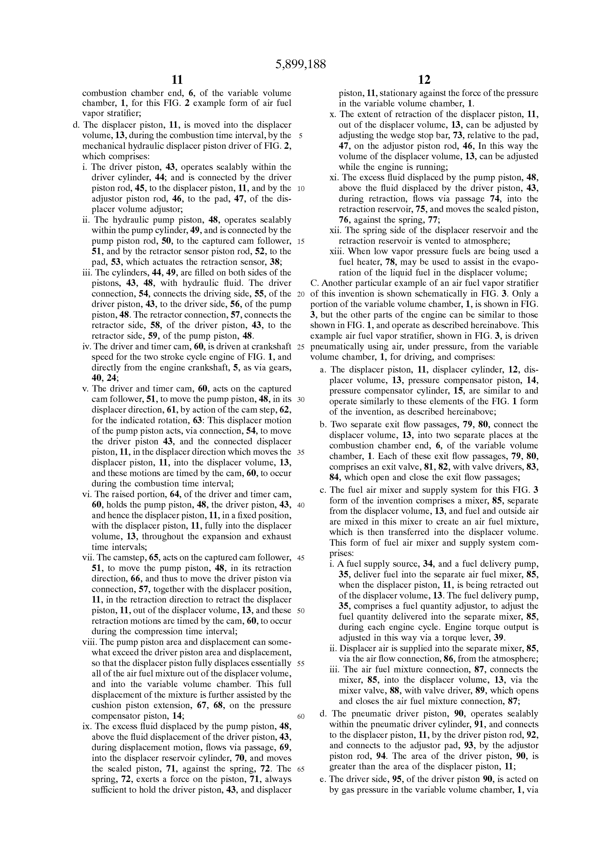
exhaust means, followed by an intake time interval, when chamber. This single fuel injector of this invention is not Said variable volume is opened to Said intake means, these Subject to a high rate of heat transfer Since burning does not two time intervals being an exhaust and intake time interval; occur within the displacer Volume. The Single fuel injector Said exhaust and intake time interval following after a of this invention can also operate at moderate injection preceding expansion time interval and preceding a next preSSure, Since fuel can be injected into the displacer Volume following compression time interval. For a four Stroke cycle rather early during compression, when preSSures are low. piston internal combustion engine each Separate time inter For these Several reasons, the fuel injectors for this invention Val occupies approximately one half engine revolution and can be of low cost, and this is another beneficial object of thus one Stroke of the piston. For a two Stroke cycle piston this invention.
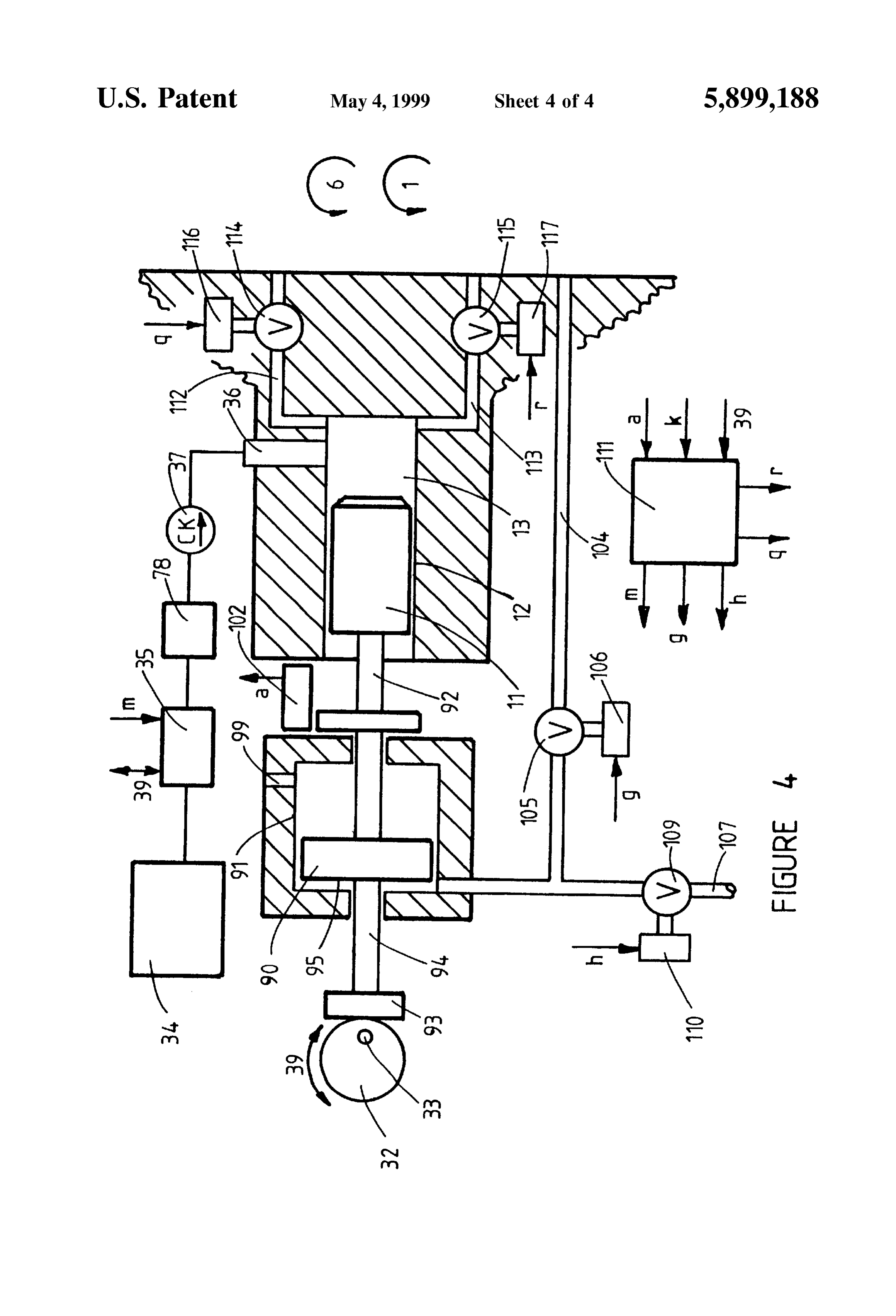
internal combustion engine the expansion time interval AS with the prior art Texaco combustion process, the air together with the exhaust time interval occupy approxi quantity within the variable volume chamber need not be mately a half engine revolution and one piston Stroke, and an adjusted for varying torque, Since a stratified mixture is used intake time interval followed by a compression time interval with the air fuel vapor stratifiers of this invention. Thus an occupy the next following half engine revolution and piston intake air throttle is unnecessary, and the pumping work loSS, Stroke. 15 due to throttling at part load, is avoided. A piston internal combustion engine further comprises a The air fuel vapor mixture within the displacer volume is Source of Supply of reactant gas containing appreciable maintained fuel rich by adjusting the displaced Volume oxygen gas to each Said intake means for admitting reactant about proportionally to the fuel quantity. As a result, the gases into Said variable Volume chamber. compression ignition delay period thereof will be very long. The combustion time interval is that portion of the com Only after this rich air fuel vapor mixture is displaced into pression and expansion time interval when burning of the air the variable volume chamber, and admixed with additional fuel mixture in the engine cylinder is intended to take place. air, is a shorter compression ignition delay period For reasons of engine efficiency this combustion time inter encountered, and ignition and burning of the now fuel leaner val is usually to occur when the variable volume chamber is mixture can take place well before expiration of this delay at or near to its minimum Volume, during or following a 25 period. Hence the knock Suppression advantages of the prior compression time interval. art Texaco combustion process are retained with the air fuel The term reactant gas containing appreciable oxygen gas Vapor Stratifiers of this invention. is used herein and in the claims to mean a reactant gas containing at least as much oxygen as is contained in the BRIEF DESCRIPTION OF THE DRAWINGS atmosphere. A mechanically driven air fuel vapor stratifier of this SUMMARY OF THE INVENTION invention is shown Schematically on a two Stroke cycle The air fuel vapor stratifiers of this invention can be used internal combustion engine in FIG. 1. A mechanical and hydraulic driven air fuel vapor stratifier to create stratified air fuel mixtures within the combustion chamber of piston internal combustion engines of either two 35 of this invention is shown schematically in FIG. 2. Stroke type or four Stroke type. A fuel rich air fuel vapor A pneumatically driven air fuel vapor Stratifier of this mixture is created within a separate displacer Volume cham invention is shown schematically in FIG. 3. ber. This rich air fuel vapor mixture is then displaced out of Another form of pneumatically driven air fuel vapor the displacer Volume, and into the variable Volume chamber stratifier of this invention is shown schematically in FIG. 4. at the combustion chamber end thereof, by a displacer 40 DESCRIPTION OF THE PREFERRED piston, during the combustion time interval. Within the EMBODIMENTS combustion chamber, the rich air fuel vapor mixture is mixed with the air in the variable volume chamber, to create 1. General Description and Benefits a fuel leaner air fuel Vapor mixture, which is then Spark The air fuel vapor stratifiers of this invention are for use ignited to initiate combustion. Complete burning of the fuel 45 as an improved means for creating a Stratified fuel and air leaner stratified air fuel vapor mixture then follows. The mixture in the variable Volume chamber of a piston type absence of any liquid fuel within the burning Zone prevents internal combustion engine, as described hereinabove, at the the formation of any appreciable Soot, and this is one of the preferred combustion time in the engine cycle. Each cylinder beneficial objects of this invention. of an engine is fitted with at least one air fuel Vapor Stratifier The fuel rich air fuel vapor mixture can flow into the 50 and each air fuel vapor Stratifier comprises the following variable Volume chamber via one or more Separate flow elements:
passages. When Several flow passages are used these can be a. A displacer comprising a displacer piston, Sealably positioned to place the Several consequent burning Zones operative within a displacer cylinder, and these enclos throughout the variable Volume chamber, in order to more ing a displacer Volume, within which an air fuel mix fully utilize the air mass available in the variable volume 55 ture can be created and contained; chamber. This is another beneficial object of this invention, b. One or more exit flow connections connect Separately that the available air mass can be largely utilized for fuel from the displacer Volume into the combustion cham burning at full power, and engine displacement, and hence ber portion of the variable volume chamber; Size and cost, need not be increased to allow for incomplete c. Adriver and driver timer for driving the displacer piston air utilization. 60 into the displacer Volume functions to displace the air To thusly create Several Separate burning Zones, using a fuel mixture out of the displacer Volume, and into the prior art Stratified Scheme, Such as the Texaco combination Variable Volume chamber, during the combustion time process, would require Several Separate liquid fuel injectors, interval, and via the exit flow passages. Preferably the each of which is expensive. The air fuel vapor stratifier of driver holds the displacer piston inside the displacer this invention can create Such several Separate burning Zones 65 Volume throughout the expansion time interval to pre by using but a single fuel injector, Since the fuel is injected vent hot burned gas backflow into the displacer vol into the displacer Volume, rather than into the combustion ume,
Page 8
S 6 d. A retractor and retractor timer retracts the displacer and other factors. Hence proper Spark electrode piston out of the displacer Volume, during a portion of positioning is best determined experimentally for the exhaust intake and compression time intervals, each particular engine design. Several Separate Spark which follow the expansion time interval. The displacer electrodes can be used and all or Some of these can Volume is then available to contain the air fuel vapor operate with a continuous Spark during the combus mixture for the next following engine cycle; tion time interval, in order to assure ignition and e. A mixture generator is used to create an air fuel vapor burning of the stratified air fuel mixture in the mixture within the displacer Volume, prior to each variable volume chamber. It will be preferable to combustion time interval. This air fuel vapor mixture prevent the Spark ignited flame from moving back can be created by injecting a fuel quantity from a into the displacer Volume, via the exit flow passages. Source, into the displacer Volume, while the displacer This can be accomplished by placing flame arresters piston is retracting during the compression time inter at the variable volume chamber end of the exit flow val. This retraction during compression Supplies the air passages. Alternatively, and preferably in many quantity from the variable Volume chamber, via the applications, the displacer air fuel vapor mixture can open exit flow passages. 15 be fuel richer than the rich Spark ignition limit and Alternatively the air fuel vapor mixture can be created in the rich inflammability limit. a separate mixer, apart from the displacer Volume. Fuel is (ii) Glow plugs, with Suitable energizers, can be used as injected into this Separate mixer, while atmospheric air is igniters in place of Spark igniters. also flowing into the Separate mixer, and on into the dis (iii) The stratified air fuel vapor mixture can be com placer Volume, via an open air fuel mixture connection, pression ignited by use of adequate engine compres during displacer piston retraction, the exit flow passages Sion ratio. Such compression ignition will occur being closed during retraction. initially in those portions of the stratified mixture To prevent backflow during the combustion time interval having the shortest compression ignition time delay when the displacer piston is moving into the displacer interval. This use of compression ignition is Volume, check valves, or similar flow controllers, are placed 25 described in my earlier filed US Patent application in the fuel Supply line or the air fuel mixture connection. In entitled, “Compression Ignition Engine Combustion this way the air fuel mixture, created inside the displaced Process,” Ser. No. 08/838720, and this material is volume, can only flow out of this volume, into the variable incorporated herein by reference thereto. AS Volume chamber, via the exit flow passages during the described therein, when compression ignition is combustion time interval; used, Several Separate exit flow passages will be f. A displacer Volume adjustor is used to adjust the preferred. To avoid compression ignition of the dis displacer Volume and hence the Volume of the air fuel placer air fuel vapor mixture, inside the displacer vapor mixture, while the engine is running. An engine Volume, very fuel rich displacer mixtures can be fuel quantity adjustor is also used to adjust the fuel used therein whose compression ignition time delay quantity per engine cycle in each air fuel mixture, 35 is very long.
created within the displacer Volume, in order to adjust i. To achieve a modified combustion process, Similar to engine torque output; the Texaco Combustion Process, but with reduced Soot g. In many engine applications, it will be preferred to formation, and more complete utilization of the avail adjust displacer Volume in proportion to fuel quantity able engine air quantity, an air fuel vapor Stratifier of So that the air quantity in each air fuel mixture inside 40 this invention can be used with one or more Spark the displacer Volume is proportional to the fuel quan igniters as follows:
tity. In this way the air to fuel ratio of the mixture can (i) The air mass inside the variable volume chamber is be kept approximately constant within desired limits, Set into rotation by use of Shrouded intake valves or h. An air fuel vapor Stratifier of this invention, as directional intake ports, described above, will inject an air fuel mixture into the 45 (ii) The air fuel vapor stratifier injects a rich air fuel combustion chamber end of the engine variable Volume mixture into the rotating air mass, chamber, during the combustion time interval. This (iii) Mixing and interdiffusion between the rich injected injected air fuel mixture will then mix with, and inter mixture and the air mass creates Spark ignitable diffuse with, the other gases Such as air, in the variable portions, and these are ignited by the Spark igniters, Volume chamber. To Start the burning of this resulting 50 (iv) Burning of the stratified air fuel mixture in the stratified air fuel mixture in the variable volume variable Volume chamber takes place. The Spark chamber, various types of ignition can be utilized, alone initiated flames progreSS into the mixture as inter or in combination, of which the following are diffusion continues to create mixture regions with examples: inflammable air fuel ratios; (i) Spark electrodes at the combustion chamber end of 55 (v) Unburned mixture regions are air alone or richer the variable Volume chamber can ignite those air fuel than the inflammable limits and these mixtures can Vapor mixture portions having an air fuel ratio within not be compression ignited. As a result engine knock the Spark ignitable limits for the fuel being used. is prevented as in the Texaco Combustion Process. These Spark electrodes require a Spark energizer and (vi) Engine torque is adjusted by adjusting the fuel timer to create the Spark during the combustion time 60 quantity and the air quantity in the displacer Volume interval. These Spark electrodes are thus to be posi only. Hence throttling of the principal engine air tioned where the adjacent Stratified mixture is Spark mass, going into the variable Volume chamber, is not ignitable. This positioning depends upon the air fuel used to control engine torque output. In this way ratio of the displacer mixture, the gas flow pattern engine friction losses to pumping work, caused by inside the variable volume chamber, the relative 65 intake throttling, is avoided, and increased engine timing of the Spark and the displacement of the efficiency results at reduced torque output as in the displacer mixture into the variable Volume chamber, Texaco Combustion Process;
Page 9
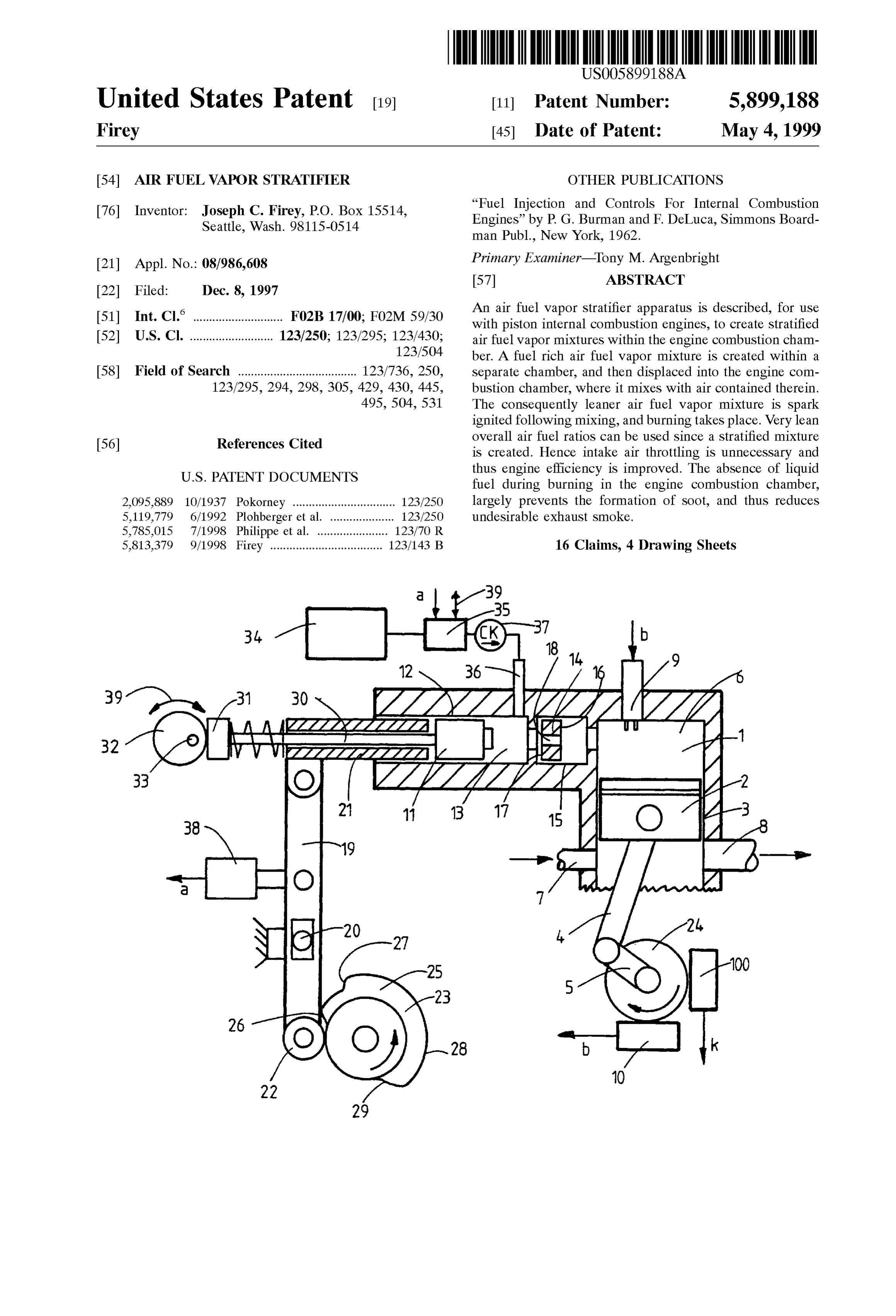
(vii) The engine fuel has been premixed with air and volume of air fuel vapor mixture into the variable largely evaporated, while inside the displacer Vol Volume chamber for each engine cycle. Were any ume. Thus, during Subsequent burning of the Strati appreciable portion of the displacer mixture retained fied mixture in the variable volume chamber, little or within the displacer Volume, through Several cycles of no soot will be formed since very little of the fuel is compression and expansion, the compression ignition a liquid therein. This is one of the beneficial objects time delay thereof could be used up, resulting in the of this invention, to obtain the antiknock and effi occurrence of compression ignition within the displacer ciency benefits of the Texaco Combustion Process, Volume. Such compression ignition within the displacer while avoiding the exhaust Soot problems conse Volume is undesirable, as causing overheating of the quent upon injecting liquid fuel into the burning displacer parts, and an increase of heat losses to the ZOneS, engine cooling jacket. The air fuel ratio mixture limits, (viii) By using Several separate exit flow passages the within which compression ignition can occur are much injected air fuel mixture can be directed into almost wider than the Spark ignition or inflammable limits, all portions of the air mass inside the variable 3. Example forms of the invention: Volume chamber. Thus at maximum torque output, 15 A. One particular example of an air fuel vapor Stratifier of almost all of the air mass in the variable volume this invention is shown schematically in FIG. 1, installed on chamber can be utilized for burning. This is another a two Stroke cycle, Single cylinder engine. The engine one of the beneficial objects of this invention, to comprises the following elements:
utilize the available engine air mass more completely a. The variable volume chamber, 1, is enclosed by the than is possible with the Texaco Combustion piston, 2, and cylinder, 3. The piston, 1, is reciprocated Process, wherein a single jet of liquid fuel is injected by action of the internal combustion engine mechanism into the air mass, comprising a connecting rod, 4, and crank and (ix) By using Several separate exit flow passages, each crankshaft, 5. This piston motion creates a cycle of equipped with an exit valve and valve driver to open variation of the volume of the variable volume and close the exit passage, the number of exit flow chamber, 1. When the piston is at top dead center, this passages, and hence the number of jets of air fuel 25 minimum volume of the variable volume defines the Vapor mixture injected into the variable Volume chamber, can be reduced as engine torque is reduced. combustion chamber end, 6, of the engine. Correspondingly the Volume of the displacer Volume b. The two stroke cycle engine of FIG. 1 comprises an is reduced in order to maintain a fuel rich mixture intake port, 7, through which air for combustion is therein. A controller is used here, responsive to Supplied into the variable Volume chamber during an engine timing and torque Setting, and operative to intake time interval when the piston, 2, has uncovered adjust fuel quantity, displacer Volume, and number of the intake port, 7.
exit flow passages opened during the combustion c. The engine of FIG. 1 further comprises an exhaust port, time interval, in approximate proportion to torque 8, through which burned gases leave the variable vol output; 35 ume chamber during an exhaust time interval when the (x) In these ways the air fuel vapor stratifiers of this piston, 2, first uncovers the exhaust port, 8; invention can be used to achieve the benefits of the d. On the piston upstroke, the air inside the variable Texaco Combustion Process, while avoiding its prin Volume, 1, is compressed, after the intake port, 7, and cipal disadvantages, exhaust port, 8, are covered by the piston, 2, during a 2. Modified forms of the invention: 40 compression time interval; . A pressure compensator piston, freely and Sealably e. On the next piston downstroke, the burned gases inside operative within a pressure compensator cylinder, can the variable Volume, 1, are expanded, during an expan be advantageously used in those engine applications Sion time interval, which ends when the exhaust port, 8, where a minimum interruption of the burning proceSS is is uncovered by the piston, 2, to commence the next desired. One side of the piston and end of the cylinder 45 exhaust time interval;
is connected to the variable Volume chamber, and the f. Whenever fuel and air are both present within the other side is connected to the displacer volume. When Variable Volume chamber, combustion can take place burning commences in the variable Volume chamber, during Such a potential combustion time interval. The the consequent rapid rise of pressure therein is actual combustion time interval commences when this transmitted, by the pressure compensator piston, into a 50 fuel air mixture is ignited, as by a Spark at Spark corresponding pressure rise in the displacer Volume. In electrodes, 9, energized from a Spark energizer and this way the flow of displacer air fuel mixture into the timer, 10. For reasons of engine cycle efficiency the variable Volume chamber, and hence the burning pro combustion time interval preferably commences during ce SS the rein, remains largely continuous and the latter portions of the compression time interval and uninterrupted, while the displacer piston is moving into 55 ends during the early portions of the expansion time the displacer Volume during the combustion time inter intervals, and the Spark energizer, 10, is timed accord val. In the absence of Such a pressure compensator ingly, scheme the flow of displacer mixture into the variable g. A two stroke cycle engine is shown Schematically in Volume will occur in pulses and a pulsating burning FIG. 1, but the air fuel vapor stratifiers of this invention process will result, 60 can also be used on four Stroke cycle engines, and other . In most engine applications it will be preferred that the equivalents, Such as the Wankel engine. displacer piston remain within the displacer Volume For this invention, each engine cylinder is equipped with throughout the engine expansion time interval, to pre at least one air fuel vapor Stratifier, connecting into the vent a backflow of hot burned gases into the displacer combustion chamber end, 6, of the variable volume Volume during displacer piston retraction; 65 chamber, 1. The example air fuel vapor stratifier shown in . In most engine applications it will be preferred that the FIG. 1 is mechanically driven from the engine crankshaft, 5, displacer piston displace essentially the entire displacer and comprises:
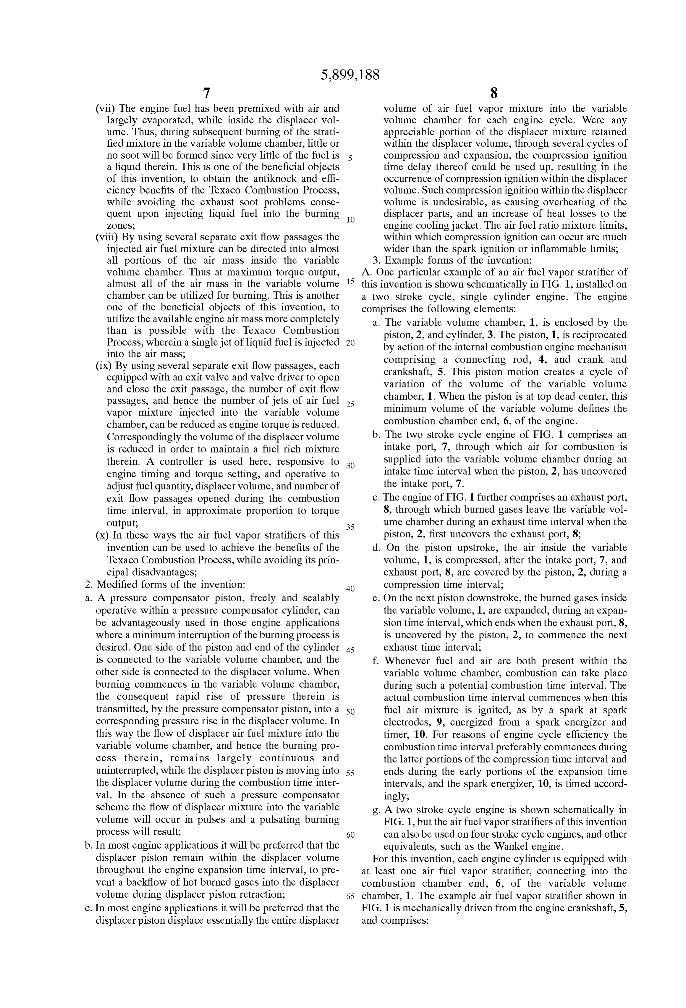
Page 10
h. The displacer piston, 11, operates Sealably within the n. For the FIG. 1 form of this invention the displacer displacer cylinder, 12, and these enclose the displacer Volume, 13, is used as the mixer, where fuel and volume, 13; displacer air are mixed to generate the displacer air fuel i. The pressure compensator piston, 14, operates freely Vapor mixture therein, prior to each combustion time and Sealably within the pressure compensator cylinder, interval. During the compression time interval, a dis 15, with one side, 16, open to the variable volume placer air portion is transferred from the variable Vol chamber, 1, and the opposite Side, 17, open to the ume chamber, 1, into the displacer Volume, 13, via the displacer volume, 13. open exit flow passage, 18. Concurrently fuel from the engine fuel source, 34, is delivered by the fuel delivery j. The single exit flow passage, 18, for this FIG. 1 1O pump, 35, and nozzle, 36, into the displacer Volume, example, passes through the pressure compensator 13, while the displacer piston, 11, is being retracted out piston, 14, to connect the displacer Volume, 13, into the of the displacer Volume during the compression time combustion chamber end, 6, of the variable volume interval. A check valve, 37, functions as a flow control chamber, 1, to prevent backflow of air fuel mixture, when the k. The displacer piston, 11, is moved into the displacer 15 displacer piston is moving into the displacer Volume, volume, 13, during the combustion time interval, by the thus assuring that the air fuel mixture flows out of the mechanical displacer piston driver of FIG. 1, which displacer volume, 13, only by way of the exit flow comprises: passage, 18, during the combustion time interval. The i. The driver lever, 19, pivoted at the fixed pivot, 20, fuel delivery pump, 35, and nozzle, 36, are timed by the connects the sleeve, 21, to the driver cam follower, displacer piston retraction Sensor, 38, to deliver fuel into the displacer Volume during retraction of the 22; displacer piston, when the displacer air is being com ii. The driver and timer cam, 23, is driven at crankshaft pressed into the displacer volume, The fuel delivery Speed, for the two Stroke cycle engine of FIG. 1, and pump, 35, delivers fuel at a preSSure greater than the directly from the engine crankshaft, 5, as via gears, preSSure in the displacer Volume, 13. 24, 25; 25 o. The fuel delivery pump, 35, and nozzle, 36, further iii. The driver and timer cam, 23, acts on the driver cam comprise a fuel quantity adjustor, to adjust the fuel follower, 22, to move the displacer piston, 11, into quantity delivered into the displacer Volume mixer, 13, the displacer Volume, 13, during the combustion for each engine cycle. Engine torque output is adjusted time interval, by action of the Stepped portions, 26, in this way, via a torque lever, 39. In order to keep the 27, of the cam, 23; fuel to air ratio of the air fuel mixture inside the iv. For the particular example displacer piston driver, displacer volume within desired limits, the volume of shown in FIG. 1, a two step, 26, 27, cam, 23, is the displacer Volume, 13, is also adjusted by the torque shown which creates a pulsed flow of displacer lever, 39, acting on the volume adjustor, 32. Volume gases into the variable Volume chamber, 1. p. Present automotive fuel Systems, slightly modified, are But a Single Such pulse may be preferred in many 35 an example of a Suitable fuel delivery pump, 35, and engine applications, for which the cam, 23, will have nozzle, 36. These present automotive fuel Systems use but a single driver Step; a common rail, Supplied with fuel at a constant preSSure v. The raised portion, 28, of the driver and timer cam, from the fuel pump, together with a Solenoid operated 23, holds the displacer piston, 11, fully into the nozzle, whose time and duration of opening are set by displacer Volume, 13, throughout the expansion time 40 an electronic controller, responsive to the engine interval, and preferably through the exhaust time throttle and an engine crank angle and cycle Sensor. For interval, So that hot burned gases do not backflow purposes of this invention, the fuel pump and common into the displacer Volume; rail would need to operate at preSSures above that vi. The retractor step, 29, on the driver and timer cam, prevailing in the displacer Volume, and nozzle opening 23, allows retraction of the displacer piston, 11, out 45 would need to be timed to coincide with displacer of the displacer Volume, 13, to take place, preferably piston retraction;
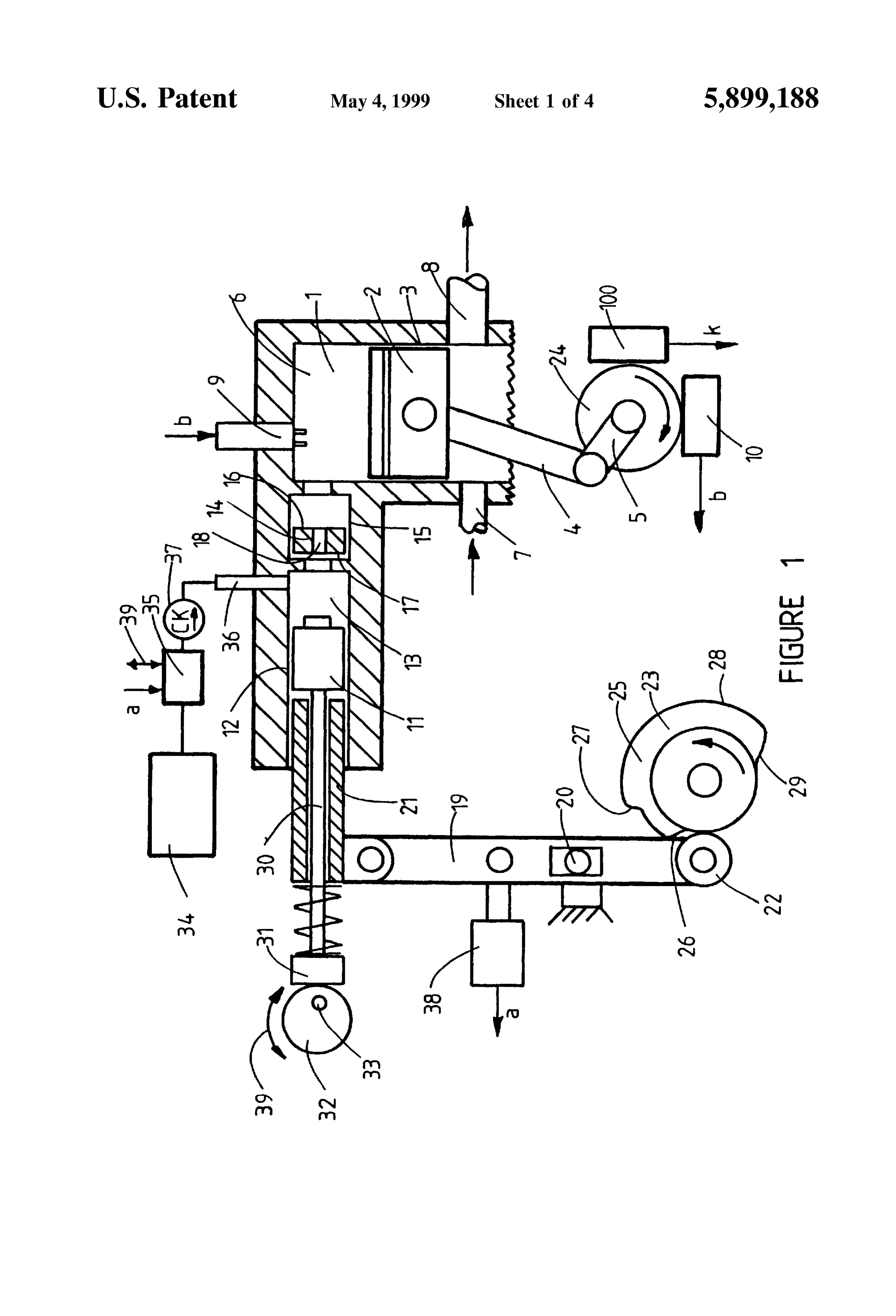
during the compression time interval, when the pres B. Another particular example of an air fuel Vapor Stratifier Sure in the variable Volume chamber, 1, acts via the of this invention is shown schematically in FIG. 2. Only a exit flow passage, 18, as a displacer piston retractor; portion of the variable volume chamber, 1, is shown in FIG. 1. The displacer piston extension bar, 30, and pad, 31, 50 2, but the other parts of the engine can be similar to those together with the volume cam, 32, rotatable about the shown in FIG. 1, and operate as described hereinabove. This center, 33, provide a Volume adjustor to adjust the example air fuel vapor stratifier, shown in FIG. 2, is driven Volume of the displacer Volume, 13, while the engine is mechanically and hydraulically from the engine crankshaft, running. The volume cam, 32, is shown in FIG. 1, 5, as by gears, 24, 40, and comprises:
adjusted for maximum displacer volume. When the 55 a. The displacer piston, 11, displacer cylinder, 12, dis cam, 32, is rotated 180 degrees, about the fixed center, placer Volume, 13, preSSure compensator piston, 14, 33, the displacer volume is minimum; and preSSure compensator cylinder, 15, are Similar to, m. For engines of moderate or higher speed, cushions, and operate similarly to, these elements of the FIG. 1 Such as pneumatic cushions, will be preferred between form of the invention, as descried hereinabove; the displacer piston, 11, and the driver sleeve, 21, to 60 b. The fuel mixer and Supply System, comprising the fuel minimize mechanical impact during displacer piston Source, 34, the fuel delivery pump, 35, and nozzle, 36, driving. Partially sealable operation of the sleeve, 21, the check valve, 37, the retraction sensor, 38, the fuel within the cylinder, 12, and on the bar, 30, could be quantity and engine torque adjustor, 39, are similar to used as Such a pneumatic cushion. Similar pneumatic and operate similarly to these elements of the FIG. 1 cushions may also be preferred within the pad, 31, 65 form of the invention as described hereinabove; acting between the pad and the Volume cam, 32, during c. Two Separate exit flow passages, 41, 42, connect the displacer piston retraction; displacer Volume, 13, into two Separate places at the
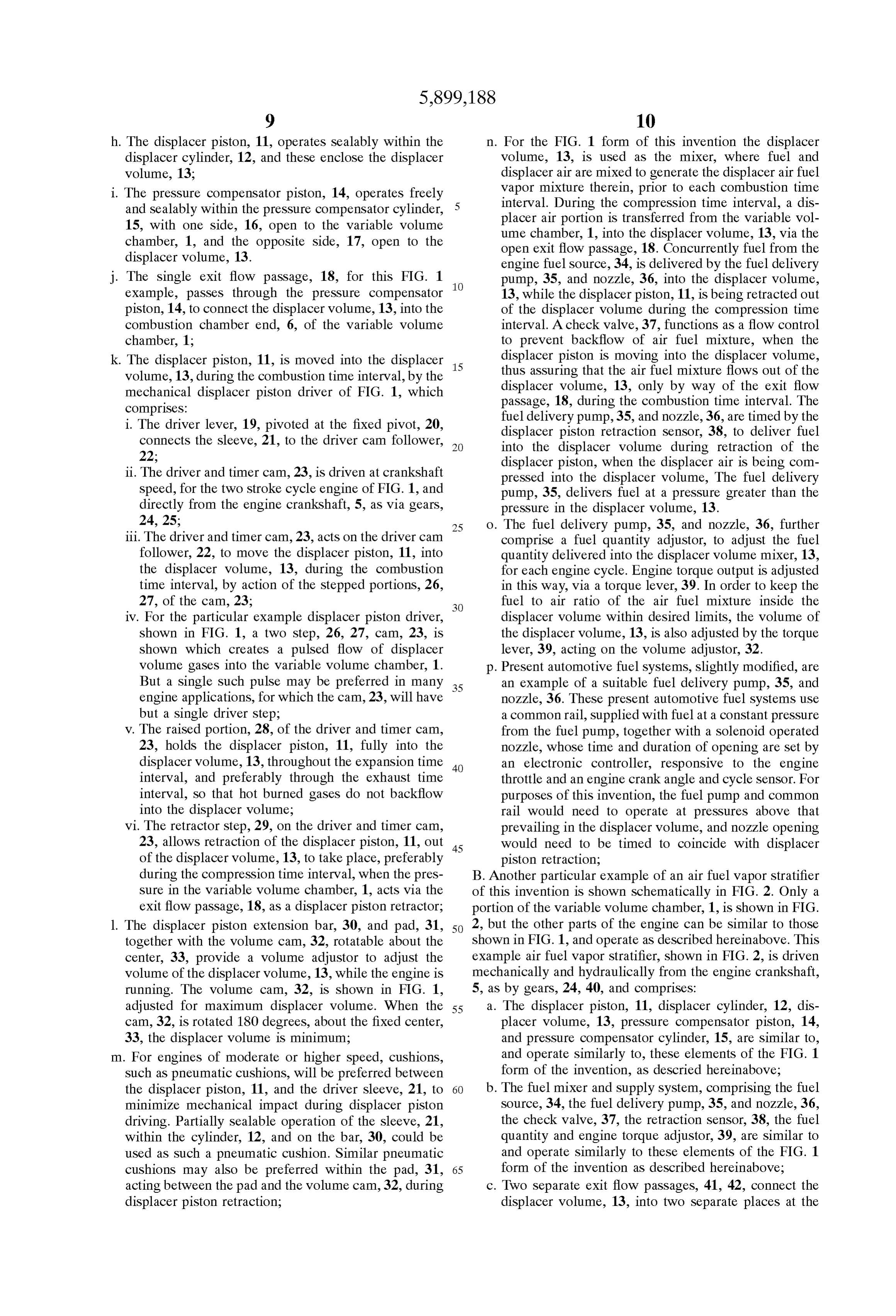
Page 11
combustion chamber end, 6, of the variable volume piston, 11, Stationary against the force of the pressure chamber, 1, for this FIG. 2 example form of air fuel in the variable volume chamber, 1. Vapor Stratifier; X. The extent of retraction of the displacer piston, 11, d. The displacer piston, 11, is moved into the displacer out of the displacer Volume, 13, can be adjusted by volume, 13, during the combustion time interval, by the adjusting the wedge Stop bar, 73, relative to the pad, mechanical hydraulic displacer piston driver of FIG. 2, 47, on the adjustor piston rod, 46, In this way the which comprises: Volume of the displacer Volume, 13, can be adjusted i. The driver piston, 43, operates sealably within the while the engine is running, driver cylinder, 44; and is connected by the driver Xi. The exceSS fluid displaced by the pump piston, 48, piston rod, 45, to the displacer piston, 11, and by the above the fluid displaced by the driver piston, 43, adjustor piston rod, 46, to the pad, 47, of the dis during retraction, flows via passage 74, into the placer Volume adjustor; retraction reservoir, 75, and moves the Sealed piston, ii. The hydraulic pump piston, 48, operates Sealably 76, against the spring, 77; within the pump cylinder, 49, and is connected by the Xii. The Spring Side of the displacer reservoir and the pump piston rod, 50, to the captured cam follower, 15 retraction reservoir is vented to atmosphere; 51, and by the retractor sensor piston rod, 52, to the xiii. When low vapor pressure fuels are being used a pad, 53, which actuates the retraction sensor, 38; fuel heater, 78, may be used to assist in the evapo iii. The cylinders, 44, 49, are filled on both sides of the ration of the liquid fuel in the displacer Volume; pistons, 43, 48, with hydraulic fluid. The driver C. Another particular example of an air fuel vapor Stratifier connection, 54, connects the driving side, 55, of the of this invention is shown schematically in FIG. 3. Only a driver piston, 43, to the driver side, 56, of the pump portion of the variable volume chamber, 1, is shown in FIG. piston, 48. The retractor connection, 57, connects the 3, but the other parts of the engine can be similar to those retractor side, 58, of the driver piston, 43, to the shown in FIG. 1, and operate as described hereinabove. This retractor side, 59, of the pump piston, 48. example air fuel vapor stratifier, shown in FIG. 3, is driven iv. The driver and timer cam, 60, is driven at crankshaft 25 pneumatically using air, under preSSure, from the variable Speed for the two stroke cycle engine of FIG. 1, and Volume chamber, 1, for driving, and comprises: directly from the engine crankshaft, 5, as via gears, a. The displacer piston, 11, displacer cylinder, 12, dis 40, 24; placer Volume, 13, preSSure compensator piston, 14, v. The driver and timer cam, 60, acts on the captured preSSure compensator cylinder, 15, are similar to and cam follower, 51, to move the pump piston, 48, in its operate similarly to these elements of the FIG. 1 form displacer direction, 61, by action of the cam Step, 62, of the invention, as described hereinabove; for the indicated rotation, 63: This displacer motion b. Two separate exit flow passages, 79, 80, connect the of the pump piston acts, via connection, 54, to move displacer Volume, 13, into two separate places at the the driver piston 43, and the connected displacer combustion chamber end, 6, of the variable volume piston, 11, in the displacer direction which moves the 35 chamber, 1. Each of these exit flow passages, 79, 80, displacer piston, 11, into the displacer Volume, 13, comprises an exit valve, 81, 82, with valve drivers, 83, and these motions are timed by the cam, 60, to occur 84, which open and close the exit flow passages, during the combustion time interval; c. The fuel air mixer and Supply system for this FIG. 3 vi. The raised portion, 64, of the driver and timer cam, form of the invention comprises a mixer, 85, Separate 60, holds the pump piston, 48, the driver piston, 43, 40 and hence the displacer piston, 11, in a fixed position, from the displacer Volume, 13, and fuel and outside air with the displacer piston, 11, fully into the displacer are mixed in this mixer to create an air fuel mixture, Volume, 13, throughout the expansion and exhaust which is then transferred into the displacer volume. time intervals, This form of fuel air mixer and Supply System com vii. The camstep, 65, acts on the captured cam follower, 45 prises:
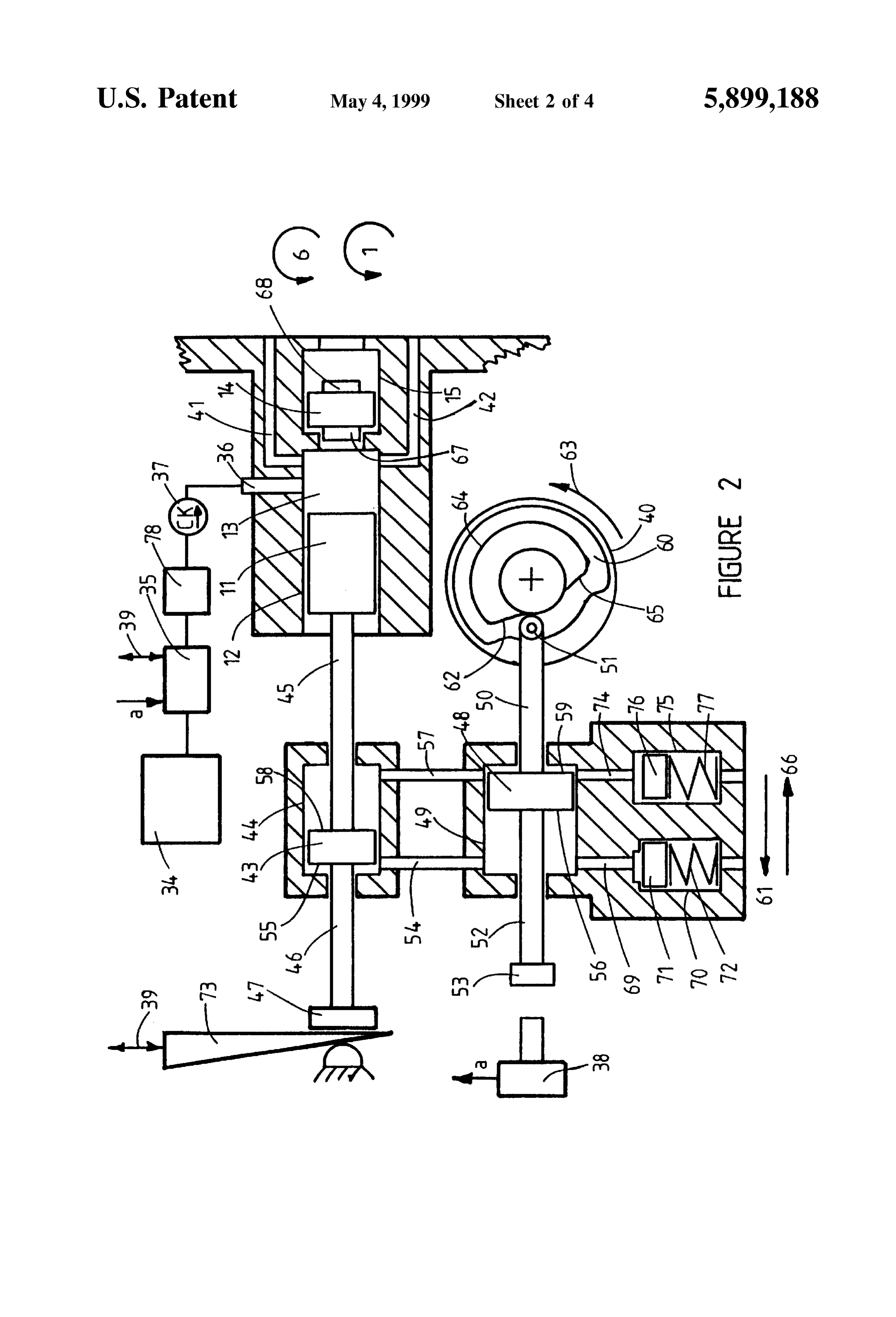
51, to move the pump piston, 48, in its retraction i. A fuel Supply Source, 34, and a fuel delivery pump, direction, 66, and thus to move the driver piston via 35, deliver fuel into the separate air fuel mixer, 85, connection, 57, together with the displacer position, when the displacer piston, 11, is being retracted out 11, in the retraction direction to retract the displacer of the displacer volume, 13. The fuel delivery pump, piston, 11, out of the displacer Volume, 13, and these 50 35, comprises a fuel quantity adjustor, to adjust the retraction motions are timed by the cam, 60, to occur fuel quantity delivered into the separate mixer, 85, during the compression time interval; during each engine cycle. Engine torque output is viii. The pump piston area and displacement can Some adjusted in this way via a torque lever, 39. what exceed the driver piston area and displacement, ii. Displacer air is Supplied into the Separate mixer, 85, So that the displacer piston fully displaces essentially 55 via the air flow connection, 86, from the atmosphere; all of the air fuel mixture out of the displacer volume, iii. The air fuel mixture connection, 87, connects the and into the variable volume chamber. This full mixer, 85, into the displacer volume, 13, via the displacement of the mixture is further assisted by the mixer valve, 88, with valve driver, 89, which opens cushion piston extension, 67, 68, on the preSSure and closes the air fuel mixture connection, 87; compensator piston, 14, 60 d. The pneumatic driver piston, 90, operates sealably ix. The excess fluid displaced by the pump piston, 48, within the pneumatic driver cylinder, 91, and connects above the fluid displacement of the driver piston, 43, to the displacer piston, 11, by the driver piston rod, 92, during displacement motion, flows via passage, 69, and connects to the adjustor pad, 93, by the adjustor into the displacer reservoir cylinder, 70, and moves piston rod, 94. The area of the driver piston, 90, is the Sealed piston, 71, against the Spring, 72. The 65 greater than the area of the displacer piston, 11; Spring, 72, exerts a force on the piston, 71, always e. The driver side, 95, of the driver piston 90, is acted on sufficient to hold the driver piston, 43, and displacer by gas pressure in the variable Volume chamber, 1, via
Page 12
the pressure connection, 96. The retraction side, 97, of automatically adjust fuel quantity in proportion to the driver piston, 90, is acted on by the retraction displacer air quantity flowing through the mixer, 85, spring, 98, and this side of the piston is vented to D. Another particular example of an air fuel vapor Stratifier atmosphere via vent, 99; of this invention is shown schematically in FIG. 4. Only a f. During the compression time interval the rising pressure portion of the variable volume chamber, 1, is shown in FIG. in the variable volume chamber, 1, acts on the driver 4, but the other parts of the engine can be similar to those side, 95, of the driver piston, 90, which moves the shown in FIG. 1, and operate as described hereinabove. This displacer piston, 11, into the displacer Volume, 13, thus example air fuel vapor stratifier, shown in FIG. 4, is driven compressing the air fuel mixture inside the displacer pneumatically using air, under preSSure, from the variable volume, 13, the mixture valve, 88, being then closed. Volume chamber, 1, for driving and retracting, and com . The controller, 101, receives inputs from an engine prises:
crank angle and cycle sensor, 100, shown in FIG. 1, and a. The displacer piston, 11, displacer cylinder, 12, dis also from a pressure Sensor, 118, of the preSSure dif placer Volume, 13, are similar to and operate Similarly ference between the displacer volume, 13, and the 15 to, these elements of the FIG. 1 and FIG. 2 forms of the variable volume chamber, 1. The controller operates the invention as described hereinabove; valve drivers, 83, 84, so that the exit flow passages, 79, b. The fuel mixer and Supply System, comprising the fuel 80, are opened when displacer Volume preSSure equals Source, 34, the fuel delivery pump, 35, and nozzle, 36, or exceeds variable Volume chamber pressure during the check valve, 37, the fuel quantity and engine torque the combustion time interval. The compressed dis adjustor, 39, are similar to and operate Similarly to placer air fuel mixture then is forced out of the dis these elements of the FIG. 2 form of the invention as placer Volume, 13, and into the combustion chamber described hereinabove;
end, 6, of the variable volume chamber, 1; c. The pneumatic driver piston 90, operates sealably . The expansion which follows after combustion causes within the pneumatic driver cylinder, 91, and connects the pressure in the variable Volume chamber, 1, to 25 to the displacer piston, 11, by the driver piston rod, 92, decrease, and this preSSure will reach approximately and connects to the adjustor pad, 93, by the adjustor atmospheric during exhaust. The retraction Spring, 98, piston rod, 94. The area of the driver piston, 90, is can then act via the piston, 90, to retract the displacer greater than the area of the displacer piston, 11; piston, 11, out of the displacer volume, 13. The retrac d. The driver side, 95, of the driver piston, 90, can be tion sensor, 102, is another input to the controller, 101, acted on by gas pressure in the variable Volume which then operates the valve driver, 89, to open the air chamber, 1, via the pressure connection, 104, with fuel mixture connection, 87, and to actuate the fuel pressure valve, 105, and valve driver, 106, which opens delivery pump, 35, to deliver the adjusted fuel quantity and closes the pressure connection, 104. Alternatively into the mixer, 85. The retraction motion of the dis the driverside, 95, of the driver piston, 90, can be acted placer piston, 11, causes air to flow into the mixer, 85, 35 on by atmospheric pressure via the vent connection, via the air connection, 86, and resultant air fuel mixture 107, with vent valve, 109, and valve driver, 110, which to flow into the displacer volume, 13, via the now open opens and closes the vent connection, 107. The retrac mixture connection, 87. The exit flow valves, 81, 82, tion side, 97, of the driver piston, 90, is vented to and exit passages, 79,80, are closed during retraction atmosphere via vent, 99;
of the displacer piston, 11, out of the displacer Volume. 40 e. Two Separate exit flow passages, 112,113, are equipped In this way the displacer volume is refilled with fresh with exit valves, 114, 115, with valve drivers, 116, 117, air fuel mixture for the next engine cycle; which open and close the exit flow passages, 112, 113; i. At maximum engine torque, all of the exit passages, 79, f. An engine crank angle and cycle Sensor, 100, shown in 80, are preferably opened, but at reduced torque, only FIG. 1, is an input to the driver timer controller, 111, Some of the exit flow passages need be open during the 45 which controls the valve drivers, 106, 110, 116, 117, so combustion time interval, Since leSS air fuel mixture is that:
being displaced into the variable Volume chamber. i. Pressure valve, 105, and pressure connection, 104, Simple check valves can be used as the exit valves, 81, are open, and vent valve, 109, and connection, 107, 82, and the Separate pressure difference Sensor, 118, is are closed, and at least one of exit valves, 114, 115, not then needed. But the number of exit flow passages 50 and exit flow passages, 112, 113, are open during the opened, during the combustion time interval, cannot combustion time interval. The driver piston, 90, thus then be adjusted in proportion to engine torque. Check forces the displacer air fuel mixture out of the Valves can alternatively be used, as pressure difference displacer Volume, 13, and into the combustion cham Sensors, in Series with controller actuated valves, 81, ber end, 6, of the variable volume chamber, 1, via 82, and a separate pressure difference Sensor, 118, will 55 those exit flow passages, 112,113, whose exit valves, not then be needed; 114, 115, are open.
j. The Volume adjustor cam, 32, provides a method for ii. Pressure valve, 105, and pressure connection, 104, adjusting the displacer Volume, 13, while the engine is remains open, and vent valve, 109, and connection, running as described hereinabove for the FIG. 1 form 107, remains closed throughout the expansion time of the invention. The displacer Volume can be adjusted 60 interval. The displacer piston will thus be held fully by the torque lever, 39, to be approximately propor inside the displacer Volume, 13, throughout the tional to fuel quantity as described hereinabove; expansion time interval to prevent backflow of hot k. An air fuel mixture heater, 103, can be used to assist the burned gases into the displacer Volume; evaporation of the fuel when low vapor preSSure fuels iii. Pressure valve, 105, and pressure connection, 104, are being used; 65 are closed, and vent valve, 109 and vent connection, 1. A conventional carburetor can be used as an alternative 107, are open, and at least one of the exit valves, 114, to the fuel delivery pump, 35, and mixer, 85, and will 115, and exit flow passages, 112, 113, are open,
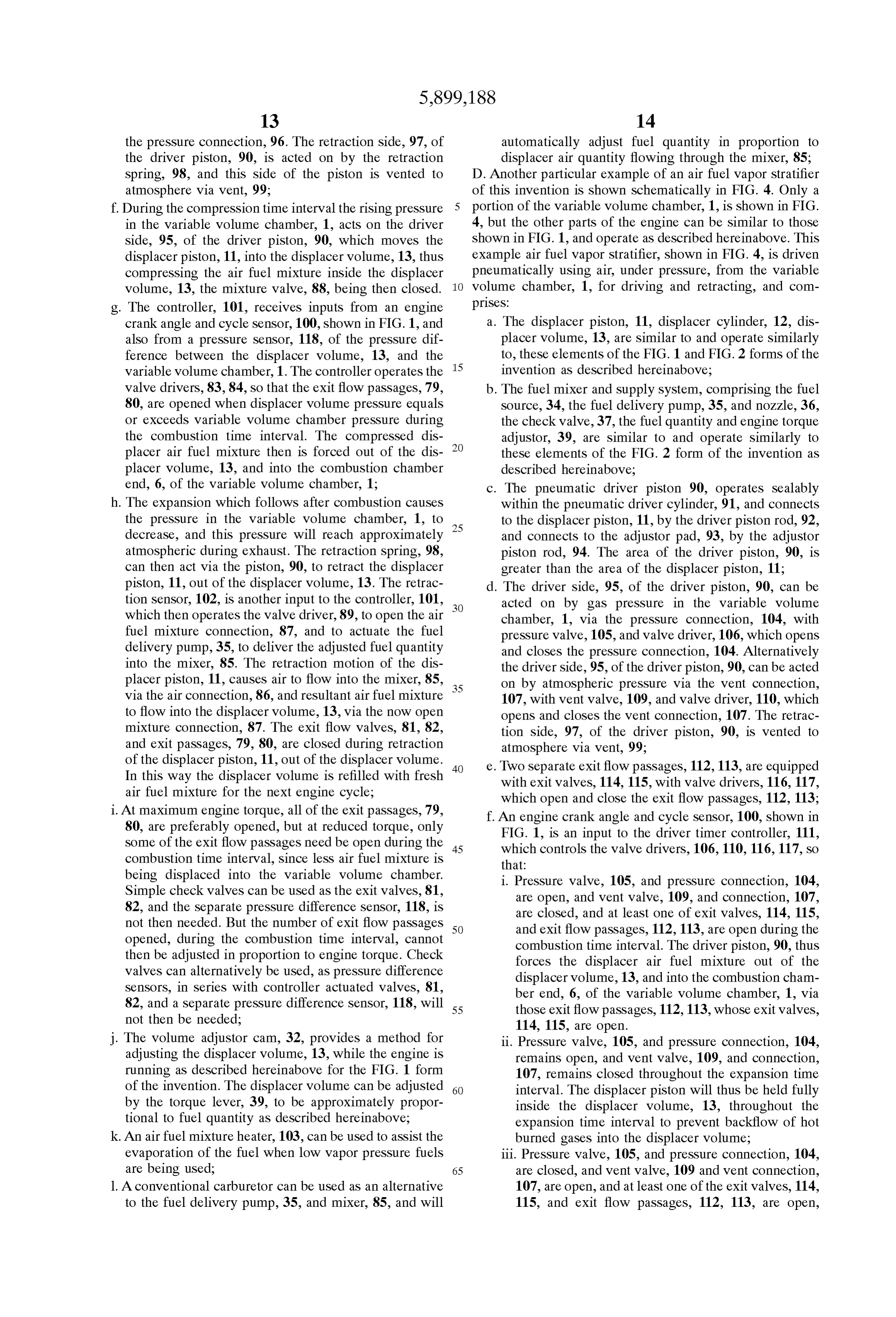
Page 13
during a portion of the compression time interval mixture heaters can be used, as described hereinabove, preceding the combustion time interval. The dis to increase the extent of fuel evaporation; placer piston, 11, is thus forced by compression b. The air fuel ratio of the displacer mixture is preferably preSSure rise in the variable Volume chamber, 1, to richer in fuel than the rich inflammability limit, in order retract out of the displacer Volume, and the driver to prevent flame flashback from the combustion cham piston, 90, is also retracted; ber into the displacer Volume; iv. At least one of the exit valves, 114, 115, and exit c. For a given engine torque output, and hence fuel flow flow passages, 112, 113, remains open throughout rate, the fuel richer the displacer mixture used, the the compression time interval, So that a fresh charge Smaller the displacer air quantity, and hence the Smaller of displacer air can be compressed into the displacer the needed displacer Volume. But use of excessively volume, 13; fuel rich displacer mixtures can result in increased Soot v. While exit valves, 114, 115, are not necessary for this formation, even when the fuel is fully evaporated; FIG. 4 form of the invention, they provide a method d. If displacer air fuel mixture ratios are used which are for adjusting the number of exit flow passages open, within the inflammable limits, flashback into the dis and hence the number of burning Zones created, in 15 placer Volume can be avoided by placing flame arrester proportion to engine torque and fuel flow rate. For Screens at the variable Volume chamber end of each exit this adjustment of the number of exit flow passages flow passage;
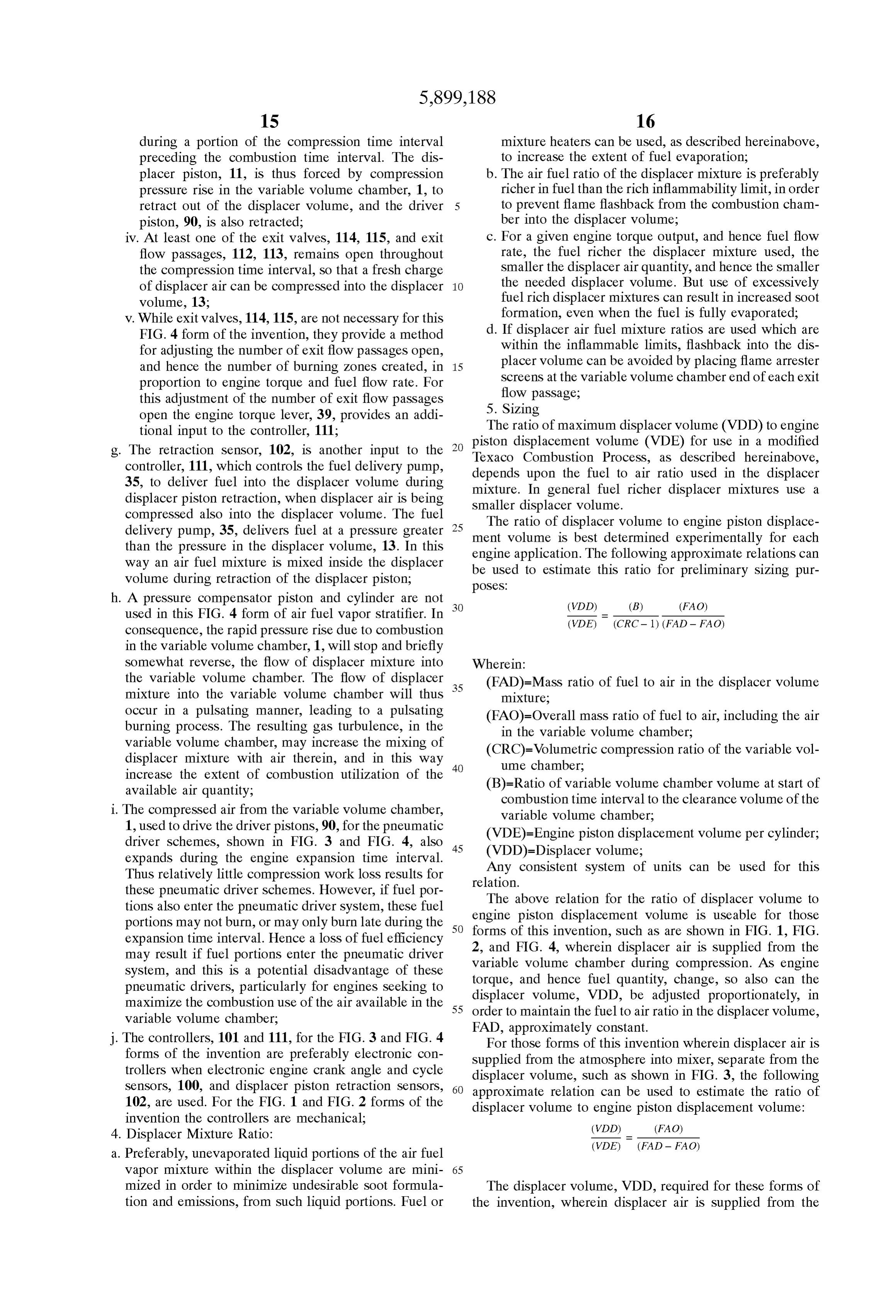
open the engine torque lever, 39, provides an addi 5. Sizing tional input to the controller, 111; The ratio of maximum displacer volume (VDD) to engine g. The retraction Sensor, 102, is another input to the Texacodisplacement piston
Combustion volume (VDE) for use in a modified
Process, as described hereinabove, controller, 111, which controls the fuel delivery pump, 35, to deliver fuel into the displacer volume during depends upon the fuel to air ratio used in the displacer displacer piston retraction, when displacer air is being mixture. In general fuel richer displacer mixtures use a compressed also into the displacer Volume. The fuel Smaller displacer Volume.
The ratio of displacer Volume to engine piston displace delivery pump, 35, delivers fuel at a pressure greater 25 ment than the pressure in the displacer Volume, 13. In this engineVolume is best determined experimentally for each application. The following approximate relations can way an air fuel mixture is mixed inside the displacer be used to estimate this ratio for preliminary sizing pur Volume during retraction of the displacer piston; pOSes:
h. A pressure compensator piston and cylinder are not used in this FIG. 4 form of air fuel vapor stratifier. In (VDD) (B) (FAO) consequence, the rapid preSSure rise due to combustion (VDE) (CRC-1) (FAD - FAO) in the variable volume chamber, 1, will stop and briefly
Somewhat reverse, the flow of displacer mixture into Wherein:
the variable volume chamber. The flow of displacer 35 (FAD)=Mass ratio of fuel to air in the displacer volume mixture into the variable volume chamber will thus mixture;
occur in a pulsating manner, leading to a pulsating (FAO)=Overall mass ratio of fuel to air, including the air burning process. The resulting gas turbulence, in the in the variable volume chamber; variable Volume chamber, may increase the mixing of (CRC)=Volumetric compression ratio of the variable vol displacer mixture with air therein, and in this way 40 ume chamber;
increase the extent of combustion utilization of the available air quantity; (B)=Ratio of variable volume chamber volume at start of combustion time interval to the clearance Volume of the i. The compressed air from the variable volume chamber, variable volume chamber; 1, used to drive the driver pistons, 90, for the pneumatic (VDE)=Engine piston displacement volume per cylinder; driver Schemes, shown in FIG. 3 and FIG. 4, also 45 (VDD)=Displacer volume;
expands during the engine expansion time interval.
Any consistent System of units can be used for this
Thus relatively little compression work loss results for relation.
these pneumatic driver Schemes. However, if fuel por The above relation for the ratio of displacer volume to tions also enter the pneumatic driver System, these fuel engine portions may not burn, or may only burn late during the 50 forms ofpiston displacement Volume is useable for those this invention, Such as are shown in FIG. 1, FIG.
expansion time interval. Hence a loSS of fuel efficiency 2, and FIG. 4, wherein displacer air is supplied from the may result if fuel portions enter the pneumatic driver variable volume
System, and this is a potential disadvantage of these torque, and hencechamber fuel during compression. AS engine quantity, change, So also can the pneumatic drivers, particularly for engines Seeking to displacer Volume, VDD, be adjusted proportionately, in maximize the combustion use of the air available in the 55 variable volume chamber; order to maintain the fuel to air ratio in the displacer Volume, FAD, approximately constant.
j. The controllers, 101 and 111, for the FIG.3 and FIG. 4 For those forms of this invention wherein displacer air is forms of the invention are preferably electronic con Supplied from the atmosphere into mixer, Separate from the trollers when electronic engine crank angle and cycle displacer volume, such as shown in FIG. 3, the following Sensors, 100, and displacer piston retraction Sensors, 60 approximate relation can be used to estimate the ratio of 102, are used. For the FIG. 1 and FIG. 2 forms of the displacer Volume to engine piston displacement Volume: invention the controllers are mechanical; (VDD) (FAO) 4. Displacer Mixture Ratio:
a. Preferably, unevaporated liquid portions of the air fuel (VDE) (FAD - FAO) Vapor mixture within the displacer Volume are mini 65 mized in order to minimize undesirable Soot formula The displacer volume, VDD, required for these forms of tion and emissions, from Such liquid portions. Fuel or the invention, wherein displacer air is Supplied from the
Page 14
atmosphere into a separate mixer, will need to be much ume chamber for compressing and expanding gases, and larger than the displacer volume for those other forms of the drive means for driving Said internal combustion engine invention, wherein displacer air is transferred from the mechanism and varying the Volume of Said chamber through variable Volume chamber during compression. repeated cycles, Said variable Volume chamber comprising a 6. An example usage of the invention: combustion chamber end at the minimum volume portion of Air fuel vapor stratifiers of this invention can be used said variable volume;
advantageously in many different internal combustion each Said variable Volume cycle comprising a compres engine applications. The following example illustrates how Sion time interval, when Said variable Volume is Sealed very large benefits can be achieved by combining the use of and decreasing, followed by an expansion time interval, air fuel vapor Stratifiers of this invention with other engine when Said variable Volume is Sealed and increasing, modifications. these two time intervals together being a compression Large improvements in automobile miles per gallon can and expansion time interval, be achieved by reducing engine friction power losses. each Said combined means for compressing and expand Engine friction losses result principally from pumping work ing further comprising intake means for admitting due to intake throttling at part load, and internal rubbing 15 reactant gases into Said variable volume chamber prior friction, particularly between piston rings and cylinder. to each said compression time interval, exhaust means Internal rubbing friction is reduced in Small displacement for removing reacted gases from Said variable Volume engines, operated at low Speeds, but Such engines have very chamber after each Said expansion time interval; poor torque and performance capabilities. High torque and each said variable Volume cycle further comprising an exhaust time interval when said variable volume is performance capabilities can be restored to Small opened to Said exhaust means, followed by an intake displacement, low Speed, engines by use of very high intake time interval when Said variable Volume is opened to Supercharging of the order of three to four atmospheres, with Said intake means, these two time intervals being an engine exhaust gas driven turbochargers. But Severe engine exhaust and intake time interval; Said exhaust and knock will occur in a low speed engine, of conventional intake time interval following after a preceding expan design when Supercharged to three or four atmospheres 25 Sion time interval and preceding a next following intake pressure. compression time interval; Said piston internal com This engine knock can be prevented by use of a modified bustion engine further comprising a Source of Supply of Texaco Combustion Process, created by use of an air fuel reactant gas containing appreciable oxygen gas, Such as Vapor Stratifier of this invention, as described hereinabove. air, to each Said intake means for admitting reactant Pumping work loSS at part load is also avoided, since intake gases into Said variable Volume chamber; each cycle of throttling is not used, engine torque being controllable by Said variable volume chamber further comprising a control of fuel flow when the resulting stratified type com potential combustion time interval comprising that por bustion is used. tion of said compression and expansion time interval Thus by combining an air fuel vapor stratifier of this during which fuel and reactant gas containing appre invention, with Small displacement, low Speed engines, 35 ciable oxygen gas are both present within Said variable using very high intake Supercharge, automobile miles per Volume chamber; each cycle of Said variable Volume gallon can be greatly increased, without Sacrifice of vehicle chamber further comprising a combustion time interval performance, or Safety, or comforts. during which the mixture of fuel and reactant gas Entirely similar miles per gallon benefits can alternatively containing appreciable oxygen gas is ignited and be obtained by a Similar use of the original Texaco Com 40 burned;
bustion Process, or by use of Small displacement, low Speed, wherein the improvement comprises adding to Said piston highly Supercharged diesel engines, which are also internal combustion engine at least one air fuel vapor unthrottled. But for both of these alternative methods, liquid stratifier for each said variable volume chamber of said fuel is injected directly into the engine combustion chamber, piston internal combustion engine, each Said air fuel resulting in a high yield of undesirable Soot and other 45 Vapor Stratifier comprising: emissions. In an air fuel Vapor Stratifier of this invention the a displacer piston Sealably operative within a displacer liquid fuel is mixed and evaporated into a separate air cylinder;
portion. The resulting air fuel vapor mixture is then injected a displacer Volume enclosed between Said displacer into the combustion chamber, and little or no Soot is formed, cylinder and Said displacer piston; Since liquid fuel is not present within the burning Zones. This 50 at least one exit flow passage between said displacer illustrates how air fuel vapor Stratifiers of this invention can Volume and Said variable Volume chamber and con achieve the benefits of the Texaco Combustion Process, necting into Said variable Volume chamber at the while escaping its Soot and emissions disadvantages. combustion chamber end thereof; 7. Mechanical displacement Volume adjustors are shown a displacer piston driver means for moving Said dis in the FIG. 1, FIG. 2, FIG. 3, and FIG. 4 forms of this 55 placer piston into Said displacer Volume, invention, but electrical adjustors, Such as Stepping motors, a displacer piston retractor means for retracting Said and other Volume adjustors can also be used for the appa displacer piston Out of Said displacer Volume; ratus and purposes of this invention. a driver timer means for timing the moving of Said 8. Several different example forms of air fuel vapor displacer piston into Said displacer Volume So that stratifies of this invention have been described hereinabove 60 the contents of Said displacer Volume are displaced for illustrative purposes. But it is not intended to limit the out of Said Volume, via Said exit flow passages, into invention thereby. Said variable Volume chamber, during Said combus Having thus described my invention, what I claim is: tion time interval;
1. In a piston internal combustion engine comprising: at a retraction timer means for timing the retraction of least one combined means for compressing and expanding 65 Said displacer piston out of Said displacer Volume, So gases, each Said combined means comprising an internal that Said retraction occurs during a portion of Said combustion engine mechanism comprising a variable Vol exhaust and intake and compression time intervals,
Page 15
a mixture generator means for creating an air fuel vapor responsive to Said engine crank angle Sensor and mixture, within Said displacer Volume, So that Said operative upon Said valve drivers in Said exit flow air fuel vapor mixture is present in Said Volume prior passages So that:
to each Said combustion time interval; at least one of Said exit flow passages is open during Said mixture generator means comprising, a Source of Said compression time interval; displacer fuel, a Source of displacer air, a mixer each of Said exit flow passages is open during at least means for mixing Said fuel into Said displacer air, a a portion of Said combustion time interval, for at flow control means for controlling the flow of said least one engine operating condition; air fuel vapor mixture, So that Said air fuel vapor throughout Said combustion time interval at least one mixture flows out of Said displacer Volume only via of Said exit flow passages is open. Said exit flow passages, 6. In an internal combustion engine as described in claim Volume adjustment means for adjusting the Volume of 1:
Said displacer Volume, while Said engine is running; wherein Said mixer means comprises an air fuel mixer fuel quantity adjustment means for adjusting the fuel Separate from Said displacer Volume; quantity in Said air fuel vapor mixture inside Said 15 wherein Said Source of displacer fuel comprises a Source displacer Volume. of engine fuel and engine fuel delivery means for 2. In an internal combustion engine as described in claim delivering Said engine fuel into Said Separate air fuel 1: mixer when Said displacer piston is being retracted out wherein Said displacer Volume is essentially fully dis of Said displacer Volume, and comprising means for placed by Said displacer piston; and further comprising: adjusting the engine fuel quantity delivered into Said a pressure compensator piston Sealably operative Separate air fuel mixer during each engine cycle; within a pressure compensator cylinder, one side of wherein Said Source of displacer air is a flow connection Said piston and end of Said cylinder being connected from the atmosphere into Said Separate air fuel mixer, to Said displacer Volume, the other Side of Said piston wherein Said mixer means further comprises an air fuel and other end of Said cylinder being connected to mixture flow connection from Said Separate air fuel said variable volume chamber at the combustion 25 chamber end thereof. mixer into Said displacer Volume, with a mixture valve 3. In an internal combustion engine as described in claim and valve driver which opens and closes Said mixture 1 and further comprising: connection;
and further comprising:
at least one Set of Spark electrodes located at the com each of Said exit flow passages comprising an exit valve bustion chamber end of Said variable volume chamber, and valve driver which opens and closes Said exit and positioned where air fuel mixture, displaced out of flow passage;
Said displacer Volume, mixes with the gases contained an engine crank angle and cycle Sensor; within said variable volume chamber; a controller means for controlling the opening and a Spark energizer and timer means for creating electric 35 closing of Said exit valves in Said exit flow passages, Sparks at Said Sets of Spark electrodes, said Sparks being and Said mixture valve in Said mixture connection, timed, relative to Said variable volume cycle, to occur responsive to Said engine crank angle and cycle during Said combustion time interval. Sensor, and operative upon Said valve drivers, So that: 4. In an internal combustion engine as described in claim each of Said exit flow passages is open during at least 1: a portion of Said combustion time interval, for at
wherein Said retraction timer means times the retraction of least one engine operating condition; Said displacer piston out of Said displacer Volume throughout Said combustion time interval at least one during a portion of Said compression time interval; of Said exit flow passages is open; wherein Said mixer means comprises said displacer Vol Said mixture valve is open during a portion of Said ume, 45 exhaust, intake, and compression time intervals, wherein Said Source of displacer air is the variable Volume and is closed during Said combustion and expan chamber, and Said displacer air is transferred from Said Sion time intervals.
variable Volume chamber, into Said displacer Volume, 7. In an internal combustion engine as described in claim Via one or more of Said exit flow passages, during Said 1:
compression time interval; 50 wherein Said displacer piston driver means, and Said wherein Said Source of displacer fuel comprises, a Source driver timer means, comprise a mechanical driver and of engine fuel and engine fuel delivery means for timer means, driven directly from Said drive means for delivering Said engine fuel into Said displacer Volume driving Said internal combustion engine mechanism, So when Said displacer piston is being retracted out of Said that Said displacer piston motion into Said displacer displacer Volume, and comprising means for adjusting 55 Volume is timed, relative to Said variable Volume cycle, the engine fuel quantity delivered into Said displacer to move Said displacer piston into Said displacer Vol Volume during each engine cycle, whereby an air fuel ume during Said combustion time interval, and So that mixture is created in Said displacer Volume. Said displacer piston is held within Said displacer 5. In an internal combustion engine as described in claim Volume throughout Said expansion time interval; 4, wherein: 60 wherein Said displacer piston retractor means and Said each of Said exit flow passages further comprises an exit retractor timer means, retract Said displacer piston out Valve and Valve driver which opens and closes Said exit of Said displacer Volume during a portion of Said intake flow passage; and compression time intervals. and further comprising: 8. In an internal combustion engine as described in claim an engine crank angle and cycle Sensor; 65 1:
a controller means for controlling the opening and wherein Said displacer piston driver means, Said driver closing of Said exit valves in Said exit flow passages, timer means, Said displacer piston retractor means, and
Page 16
Said retractor timer means, comprise a mechanical displacer Volume, and comprising means for adjusting driver, retractor, and timer means, driven directly from the engine fuel quantity delivered into Said displacer Said drive means for driving Said internal combustion Volume during each engine cycle, whereby an air fuel engine mechanism, So that: mixture is created in Said displacer Volume. Said displacer piston moves into Said displacer Volume 5 11. In an internal combustion engine as described in claim during Said combustion time interval; 10 and further comprising:
Said displacer piston is held within Said displacer each of Said exit flow passages comprising an exit valve Volume throughout Said expansion time interval; and valve driver which opens and closes said exit flow Said displacer piston is retracted out of Said displacer passage,
Volume during a portion of Said intake and compres an engine crank angle and cycle Sensor; Sion time intervals. a controller means for controlling the opening and closing 9. In an internal combustion engine as described in claim of Said exit valves, in Said exit flow passages, respon 1: Sive to Said engine crank angle Sensor, and operative wherein Said displacer piston driver comprises: upon Said valve drivers in Said exit flow passages, So that:
a displacer piston pneumatic driver means for moving 15 at least one of Said exit flow passages is open during Said displacer piston into Said displacer Volume, and Said compression time interval; comprising a driver piston, Sealably operative within each of Said exit flow passages is open during at least a driver cylinder, and connected to Said displacer a portion of Said combustion time interval, for at piston, the area of Said driver piston being larger than least one engine operating condition; the area of Said displacer piston; throughout Said combustion time interval at least one of that Side of Said driver cylinder, opposite to the con Said exit flow passages is open. nection to the displacer piston, comprising a vent 12. In an internal combustion engine as described in claim connection to atmosphere, with a vent valve and 11, and further comprising:
Valve driver which opens and closes Said vent con at least one set of Spark electrodes located at the com
bustion chamber end of Said variable volume chamber, that Side of Said driver cylinder, opposite to the con and positioned where air fuel mixture, displaced out of nection to the displacer piston, comprising a pressure Said displacer Volume, mixes with the gases contained connection to the combustion chamber end of Said within said variable volume chamber; variable Volume chamber, with a preSSure valve and a Spark energizer and timer means for creating electric Valve driver which opens and closes Said pressure Sparks at Said Sets of Spark electrodes, said Sparks being connection; timed, relative to Said variable volume cycle, to occur that side of said driver cylinder connected to the during Said combustion time interval. displacer piston being Vented to atmosphere, 13. In an internal combustion engine as described in claim wherein Said driver timer means comprises: 12:
an engine crank angle and cycle Sensor; 35 wherein Said displacer piston driver means, and Said a controller means for controlling the opening and driver timer means, comprise a mechanical driver and closing of Said vent valve in Said vent connection, timer means, driven directly from Said drive means for and Said pressure valve in Said pressure driving Said internal combustion engine mechanism, So connection, responsive to Said engine crank angle that Said displacer piston motion into Said displacer and cycle Sensor, and operative upon Said valve 40 Volume is timed, relative to Said variable Volume cycle drivers, So that: to move Said displacer piston into Said displacer Vol Said vent valve is open during a principal portion ume during Said combustion time interval, and So that of Said compression time interval; Said displacer piston is held within Said displacer Said vent valve is closed during Said combustion Volume throughout Said expansion time interval; time interval and Said expansion time interval; 45
Said pressure valve is open during Said combus wherein Said displacer piston retractor means and Said tion time interval and Said expansion time retractor timer means retract Said displacer piston out of Said displacer Volume during a portion of Said intake interval; and compression time intervals.
Said pressure valve is closed when Said vent valve 14. In an internal combustion engine as described in claim
10. In an internal combustion engine as described in claim wherein Said mixer means comprises an air fuel mixer where Said retraction timer means times the retraction of
Separate from Said displacer Volume;
Said displacer piston out of Said displacer Volume 55 wherein Said Source of displacer fuel comprises a Source during a portion of Said compression time interval; of engine fuel, and engine fuel delivery means for delivering Said engine fuel into Said Separate air fuel wherein Said mixer means comprises said displacer Vol mixer when Said displacer piston is being retracted out ume, of Said displacer Volume, and comprising means for wherein Said Source of displacer air is the variable Volume adjusting the engine fuel quantity delivered into Said chamber and Said displacer air is transferred from Said 60 Separate air fuel mixer during each engine cycle; variable Volume chamber, into Said displacer Volume, wherein Said Source of displacer air is a flow connection Via one or more of Said exit flow passages, during Said from the atmosphere into Said Separate air fuel mixer, compression time interval; wherein Said mixer means further comprises an air fuel wherein Said Source of displacer fuel comprises a Source mixture flow connection from Said Separate air fuel of engine fuel and engine fuel delivery means for 65 mixer into Said displacer Volume, with a mixture valve delivering Said engine fuel into Said displacer Volume and valve driver which opens and closes Said mixture when Said displacer piston is being retracted out of Said connection;
Page 17
each of Said exit flow passages comprising an exit valve Said displacer Volume, mixes with the gases contained and valve driver which opens and closes said exit flow within said variable volume chamber; passage, a Spark energizer and timer means for creating electric and further comprising: Sparks at Said Sets of Spark electrodes, said Sparks being an engine crank angle and cycle Sensor; timed, relative to Said variable volume cycle, to occur a controller means for controlling the opening and during Said combustion time interval. closing of Said exit valves in Said exit flow passages, 16. In an internal combustion engine as described in claim and Said mixture valve in Said mixture connection, 15:
responsive to Said engine crank angle and cycle
Sensor, and operative upon Said valve drivers, So that: wherein Said displacer piston driver means, Said driver each of Said exit flow passages is open during at least timer means, Said displacer piston reactor means, and a portion of Said combustion time interval, for at Said retractor timer means, comprise a mechanical least one engine operating condition; driver, retractor, and timer means, driven directly from throughout Said combustion time interval at least one Said drive means for driving Said internal combustion of Said exit flow passages is open; 15 engine mechanism So that:
Said mixture valve is open during a portion of Said Said displacer piston moves into Said displacer Volume exhaust, intake, and compression time intervals, during Said combustion time interval; and is closed during Said combustion and expan Said displacer piston is held within Said displacer Sion time intervals. Volume throughout Said expansion time interval; 15. In an internal combustion engine as described in claim Said displacer piston is retracted out of Said displacer 14, and further comprising: Volume during a portion of Said exhaust, intake, and at least one Set of Spark electrodes located at the com compression time intervals. bustion chamber end of Said variable volume chamber, and positioned where air fuel mixture, displaced out of
Provenance
- Collection
- Cited prior art
- Original PDF
- patentimages.storage.googleapis.com →
- Filed
- 1997-12-08
- Pages
- 17
- Method
- pdftotext (the PDF's own text layer) + pdftoppm 300dpi page scans
- Source
- Google Patents bibliographic record
- Granted
- 1999-05-04
- Inventors
- Joseph C. Firey
- Transcribed from
- patentimages.storage.googleapis.com →