patent · US4213435
Air/fuel ratio regulator
22 July 1980
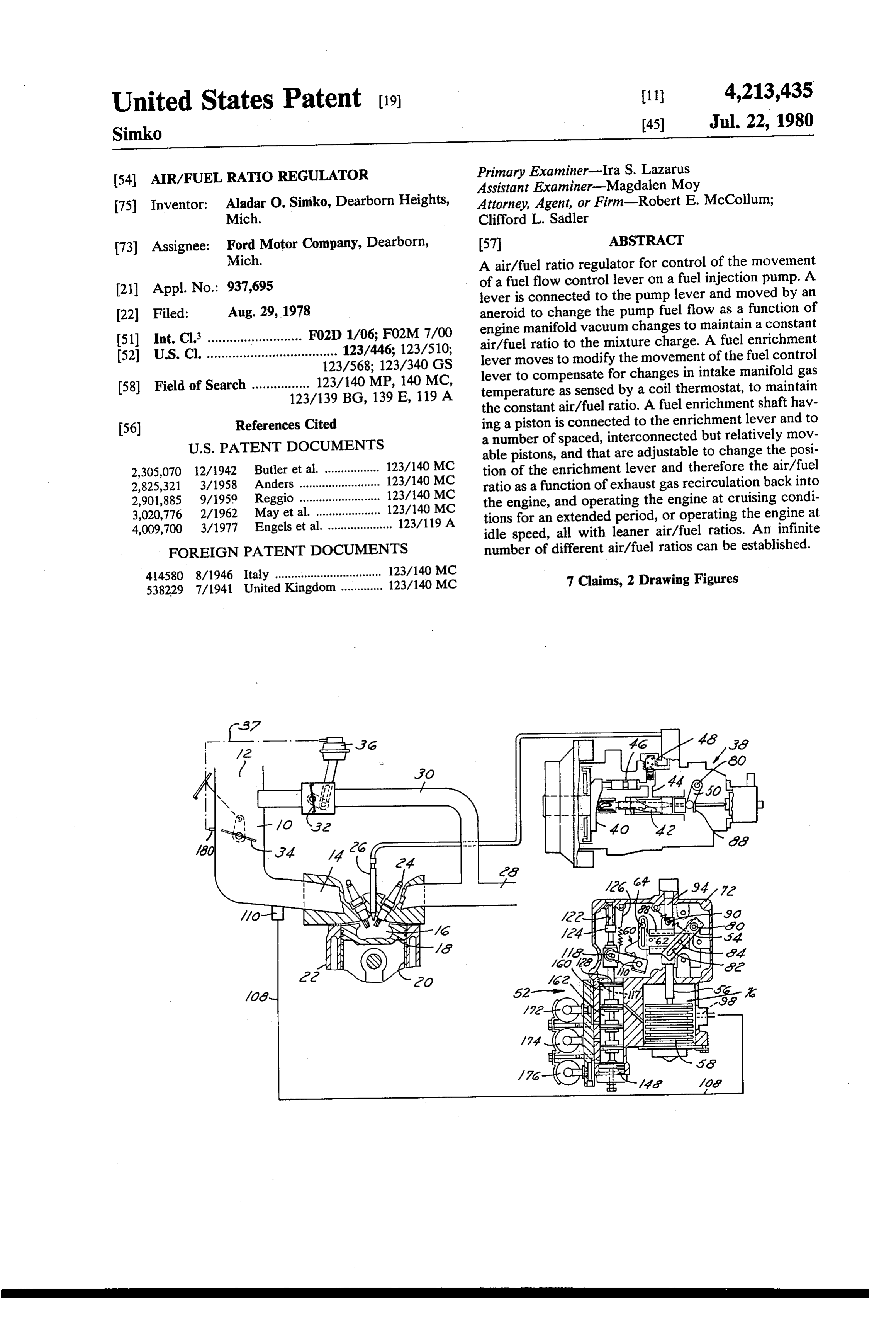
Page 1 — bibliographic record
United States Patent (19) (11) 4,213,435 Simko 45) Jul. 22, 1980
54 AIR/FUEL RATO REGULATOR Primary Examiner-Ira S. Lazarus Assistant Examiner-Magdalen Moy 75 Inventor: Aladar O. Simko, Dearborn Heights, Attorney, Agent, or Firm-Robert E. McCollum; Mich. Clifford L. Sadler 73) Assignee: Ford Motor Company, Dearborn, 57 ABSTRACT Mich. A air/fuel ratio regulator for control of the movement
of a fuel flow control lever on a fuel injection pump. A lever is connected to the pump lever and moved by an 22 Filed: Aug. 29, 1978 aneroid to change the pump fuel flow as a function of engine manifold vacuum changes to maintain a constant (51) Int. Cl. ............. . . . . . . . . . . . . . F02D 1/06; F02M 7/00 air/fuel ratio to the mixture charge. A fuel enrichment 52) U.S. C. .................................... 123/446; 123/510;
123/568; 123/340 GS lever moves to modify the movement of the fuel control lever to compensate for changes in intake manifold gas
123/139 BG, 139 E, 119 A temperature as sensed by a coil thermostat, to maintain the constant air/fuel ratio. A fuel enrichment shaft hav 56) References Cited ing a piston is connected to the enrichment lever and to
able pistons, and that are adjustable to change the posi
2,305,070 2/1942 Anders tion of the enrichment lever and therefore the air/fuel 2,825,321 3/1958 ............. ... 123/140 MC ratio as a function of exhaust gas recirculation back into 2,901,885 9/1959 Reggio ......... ... 123/140 MC the engine, and operating the engine at cruising condi 3,020,776 2/1962 May et al. ... ... 123/140 MC tions for an extended period, or operating the engine at 4,009,700 3/1977 Engels et al. .................... 123/119A idle speed, all with leaner air/fuel ratios. An infinite FOREIGN PATENT DOCUMENTS number of different air/fuel ratios can be established. 414580 8/1946 Italy ................................. 123/140 MC 7 Claims, 2 Drawing Figures
Page 2
Drawing sheet — no readable text.
Page 3
Drawing sheet — no readable text.
Page 4
fuel economy; can provide different leaner air/fuel
AIR/FUEL RATIO REGULATOR ratios than the base ratio for operating the engine at different idle speeds and decelerating conditions of
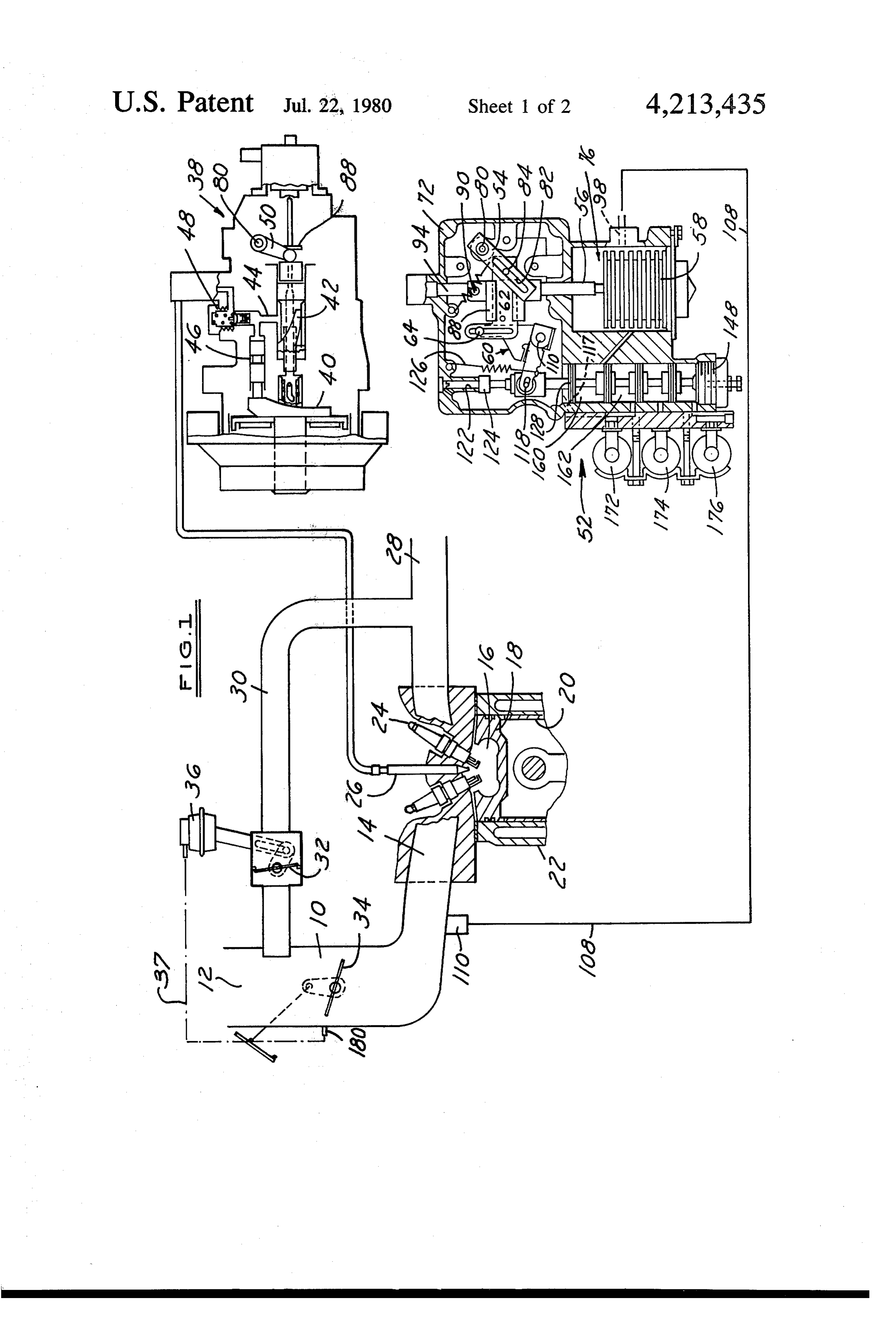
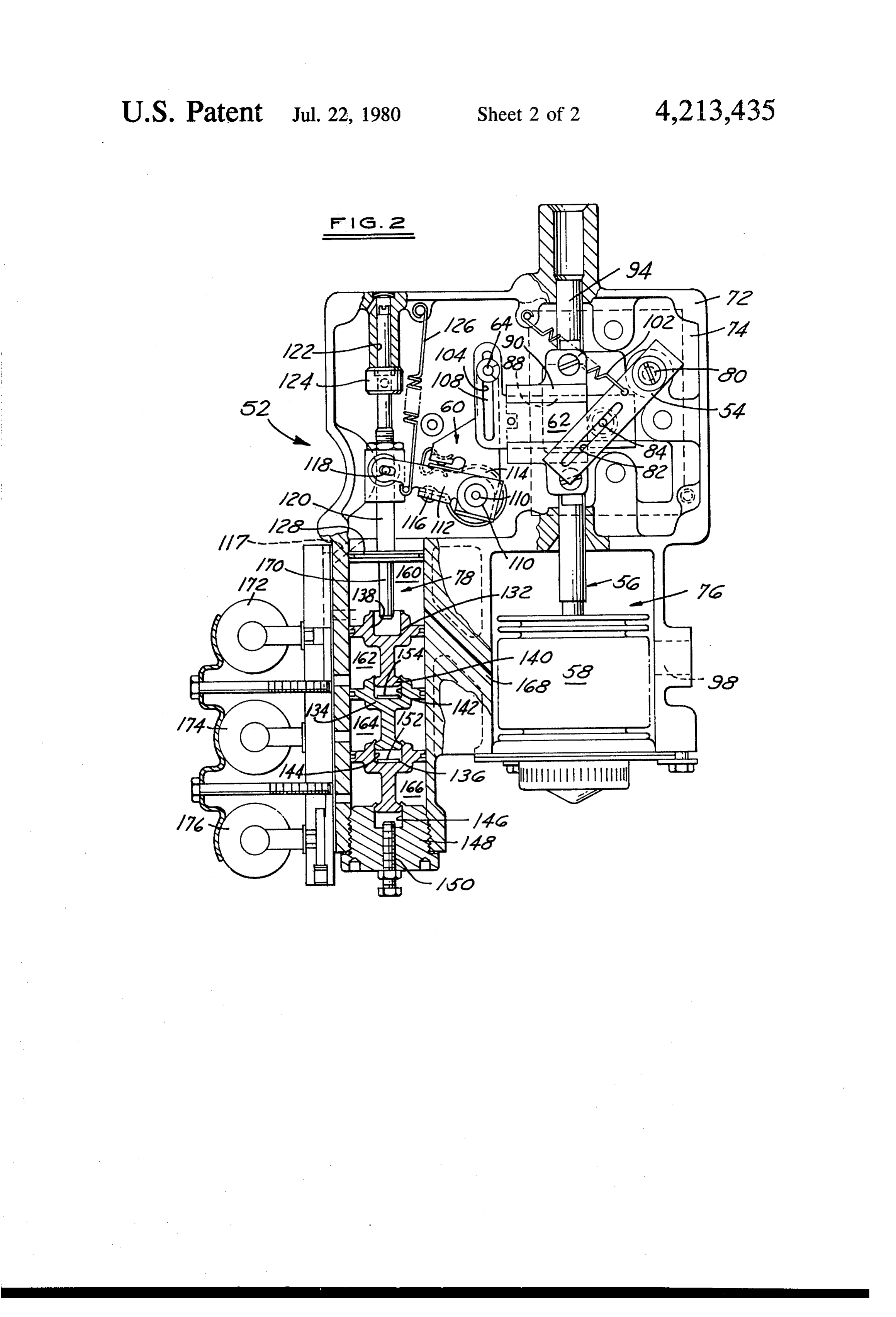
This invention relates in general to a fuel injection operation for better emission control; and can maintain system for an internal combustion engine. More particu the engine at the base ratio even though the recircula larly, it relates to an air/fuel ratio regulator that is an tionIt of exhaust gases is desired to control Nox emissions. is a still further object of the invention to provide improvement over the invention shown and described an air/fuel ratio regulator of the type described above in in my copending United States patent application Ser.
No. 937,693, filed Aug. 29, 1978, and entitled AIR/F- 10 which the fuel enrichment lever is normally biased to a maximum enrichment position and movable in the op
Ser. No. 937,693 shows and describes and air/fuel posite direction in response to intake manifold vacuum, ratio controller that operates in conjunction with a fuel the lean air/fuel ratio setting position being established injection pump having a fuel output that varies in direct by a number of adjustable fluid pressure control devices proportion to engine speed changes to match fuel flow independently operable and adjustable so as to provide with engine mass airflow characteristics over the entire 15 anOtherinfinite number of lean air/fuel ratio settings. objects, features and advantages of the inven engine speed and load conditions of operation. The controller has a main air/fuel ratio regulator consisting tion will become more apparent upon reference to the succeeding detailed description thereof and to the of a vacuum aneroid responsive to changes in intake drawings illustrating the preferred embodiment thereof; manifold vacuum level to move the injection pump fuel 20 control lever to a position to maintain a constant air/f. wherein, uel mixture change ratio at all times. A fuel enrichment bustion FIG. 1 is a schematic illustration of an internal com control lever is provided to modify the actions of the engine fuel injection system embodying the aneroid to compensate for changes in the oxygen con invention; and, tent in the mixture due to the addition of, for example, of FIG. 2 is a cross-sectional view on an enlarged scale exhaust gases that are recirculated back into the mani 25 tion.the regulator shown in FIG. 1 embodying the inven fold, and/or changes in the intake gas temperature. A manual override of the fuel enrichment lever after it has FIG. 1 illustrates schematically a portion of the in reached the zero EGR flow position will also modify duction internal and exhaust system of a fuel injection type combustion engine in which is incorporated the the air/fuel ratio of maximum fuel enrichment at essen tially wide open throttle conditions of operation of the 30 air/fuel ratio regulator of this invention. More specifically, the system includes an air-gas in engine. However, the latter override is the only vari take ance from a constant air/fuel ratio regulation of the fuel end 12manifold to air at induction passage 10 that is open at one essentially atmospheric or ambient pres pump provided by the controller of Ser. No. 937,693.
sure level and is connected at its opposite end 14 to
This invention is directed to an air/fuel ratio regula discharge tor that maintains a constant air/fuel ratio as in Ser. No. 35 combustionthrough valving (not shown) into a swirl type chamber indicated schematically at 16. The 937,693 by means of a manifold vacuum responsive chamber in this case is formed in the top of a piston 18 aneroid mechanism. It also includes a fuel enrichment control lever. However, in this invention, the enrich slidably mounted in the bore 20 of a cylinder block 22. ment lever is movable to various positions to establish The chamber has a pair of sparkplugs 24 for the ignition different air/fuel ratios to the mixture charge. In other of the intake mixture charge from the induction passage words, this invention is directed to an air/fuel ratio 14 and the fuel injected from an injector 26 providing a regulator that permits the establishment of an infinite locally rich mixture and overall lean cylinder charge. number of different air/fuel ratio settings to satisfy dif An exhaust gas conduit 28 is connected to a passage 30 ferent engine operating requirements, the settings again that recirculates a portion of the exhaust gases past a being attained by movement of the fuel injection pump 45 vacuum opened, spring closed EGR valve 32 to a point flow control lever to change the fuel flow output. near the inlet to the induction passage 10 and above the Therefore, it is an object of this invention to provide closed position of a conventional throttle valve 34. a fuel injection system air/fuel ratio regulator that per Thus, movement of the throttle valve 34 provides the mits independent adjustments to establish various air/f- total control of the mass flow of gas (airplus EGR) into uel ratios of the mixture charge flowing to the engine 50 theThe engine cylinder.
EGR valve is rotatable by a vacuum servo mech
More particularly, it is an object of this invention to anism 36 that is connected by a line indicated schemati provide a fuel injection system air/fuel ratio regulator cally at 37 to a port 180 above the closed position of the that establishes a base constant air/fuel ratio to the throttle valve 34. Opening of the throttle valve directs mixture charge supplied to the engine combustion 55 vacuum to the servomechanism to provide a flow of exhaust gases during the load conditions of operation of chamber by moving the fuel injection pump flow con the engine.
trol lever to increase or decrease fuel flow as a function The fuel in this case delivered to injector 26 is pro of changes in intake manifold vacuum, and establishes vided further air/fuel ratios leaner and/or richer than the base that is byshown a fuel injection pump 38 of the plunger type and described more fully in my applica air/fuel ratio to fulfill various operating conditions of 60 tion U.S. Ser. No. 937,693 referred to above. The details the engine not satisfied by the base air/fuel ratio. of construction and operation of the pump are fully It is another object of the invention to provide a described in the above U.S. Ser. No. 937,693 and, there regulator of the type described above having a fuel enrichment lever that can be moved to a position pro fore, are not repeated since they are believed to be viding richer air/fuel ratios than the base ratio, for 65 unnecessary for an understanding of the invention. Suf maximum engine acceleration purposes; can provide fice it to say, however, that the pump has a cam face 40 leaner air/fuel ratios than the base ratio during extended that is contoured to match fuel pump output with the periods of cruising operation of the engine, for better mass air flow characteristics of the engine for all engine
Page 5
speed and load conditions of operation so as to maintain projecting through the housing into chamber 76 for a constant air/fuel ratio to the mixture charge flowing attachment to the end of abellows type metallic aneroid into the engine combustion chamber 16 at all times. The 58. The aneroid 58 is sealed with vacuum inside and pump is shown with an axially movable fuel metering subjected to intake manifold absolute pressure (vacuum) sleeve valve helix 42 that cooperates with a spill port 44 admitted to chamber 76 through an inlet 98 connected to block the same at times to thereby permit the output to tubing indicated schematically by the line 108 shown from the plunger 46 of the pump to build up a pressure in FIG. 1. The changes in manifold vacuum level cause against a delivery valve 48 to open the same and supply an expansion or contraction of the aneroid to move the fuel to the injector 26. Axial movement of the helix by . shaft 56 vertically causing roller 84 to pivot the fuel a fuel flow control lever 50 will vary the base fuel flow 10 control lever 54.
output rate by moving the helix to block or unblock a The cross slide 62 has formed on its left end as seen in spill port 44 for a different period of time. FIG. 2 an elongated cam slot 104 within which moves This invention is directed to an air/fuel ratio regula the floating roller 64. The roller is pivotally attached to tor that will establish a base mixture air/fuel ratio and one leg of the fuel enrichment control bellcrank lever 60 maintain it constant, but can also establish a number of 15 pivotally mounted at 110 to the housing 72 and having other mixture air/fuel ratios as satisfy specific engine a right angled leg portion 112 fixed to the pivot shaft. operating conditions, provide better emission control, The two leg portions of the bellcrank can move relative and increase fuel economy. The regulator is connected to one another but normally move together. Let 108 is to the fuel pump lever 50 to change the fuel flow output pivotally connected to leg 112 and normally clamped as a function of manifold vacuum changes (air flow 20 together by a thermostatically responsive coil spring changes) upon opening of the throttle valve 34. The member 114 anchored to the leg 112 at 116 and an regulator also changes the fuel flow upon the addition chored at its opposite end to the leg 108. The cavity 74 of EGR gases to the intake charge; to compensate for in which lever 60 is located is exposed to the tempera the change in oxygen concentration changes the ratio to ture of the intake manifold gas flow through a passage lean out the mixture for better fuel economy during 25 117. When the temperature level varies from the setting extended periods of the engine operating at cruise con of the coiled spring, its thermal expansion causes a ditions; and changes the ratio to lean the mixture for movement of the leg 108, and roller 106 relative to the different engine idle speed and deceleration operation. leg 112 to adjust the position of the cross slide 62 and The regulator is illustrated in general in FIG. 1 at 52, thereby adjust the position of fuel control lever 54 and and more particularly in FIG. 2. In general, it contains 30 pump lever 50 to change the fuel flow and maintain a a vacuum-mechanical linkage mechanism that includes constant base air/fuel ratio by compensating for the an arcuately movable fuel control lever 54 that is con changes in density of the gas.
nected to the fuel injection pump fuel lever 50 (FIG. 1). The leg 112 of the fuel enrichment control lever 60 is It also contains a fuel flow output control rod 56 that is connected by a pin and slot type adjustable connection connected to an aneroid 58 to be responsive to intake 35 118 to a fuel enrichment control rod 120. Rod 120 at one manifold vacuum changes, and a fuel enrichment link end is piloted in a bore 122 in the housing 72 and has an age or fuel ratio changing linkage 60. Linkage 60 is adjustable stop 124 for fixing the maximum fuel delivery connected to the rod 56 and lever 54 by a cross slide 62 position of the enrichment control lever 60. A spring and floating roller 64 and moves in response to the flow 126 normally biases the lever 60 against the stop 124 to of EGR gases and the attainment of other engine oper the maximum engine acceleration position providing ating conditions to be described to establish other A/F the largest rate of fuel flow.
ratios. The opposite end of enrichment rod 120 is formed More specifically, the regulator 52 has a shell-like with an enrichment piston 128 slidably movable in the housing 72 defining a main chamber 74, a barometric constant diameter bore of chamber 78. Also slidably pressure responsive chamber 76, and a chamber 78 con 45 mounted in the bore are three additional axially aligned taining a number of servo mechanisms for controlling and movable pistons 132, 134, and 136. The latter pis the establishment of air/fuel ratios to the mixture tons are T-shaped in cross-section as shown and nested charge that are different from the base A/F ratio. The or interconnected with each other for a limited relative housing 72 contains a number of mounting lugs or movement between contiguous piston portions. That is, bosses on one of which is pivotally mounted a control 50 the end of enrichment rod 120 cooperates with a recess shaft 80 on which is fixed the fuel lever 54 and fuel 138 in piston 132, the stem end 140 of piston 132 is pump fuel lever 50 (FIG. 1) 50 (FIG. 1) 54, therefore, is slidably mounted within a recess 142 in piston 134, the operatively pivotally connected to the fuel injection stem end of piston 134 is slidably mounted within a pump metering sleeve valve helix 42 shown in FIG. 1 so recess 144 in piston 136, and the stem end of piston 136 that counterclockwise movement of lever 54 will cause 55 is slidably mounted within a recess 146 in the end plate a movement of the pump helix to increase the fuel flow 148 that is screwed into the open end of the bore in output or rate of flow. A spring 102 anchored to the housing 72. A further adjustable screw 150 is provided housing normally biases the fuel control lever in a projecting into the bore 146 to vary the relative expan clockwise direction to a minimum or base fuel flow sion between the end cap and piston 136. A pair of shims position of the fuel metering sleeve valve helix 42 152,154 of varying thicknesses may also be provided in shown in FIG. 1. the recesses 144 and 142 to control the amount of back The lever 54 is formed with an elongated cam slot 82 lash or extension of the parts.
through which projects a roller 84 that is mounted in As noted previously, the diameters of all of the pis cross slide member 62. The cross slide is mounted for a tons is the same. Vacuum admitted to any of the cham sliding movement within a channel 88 formed in a cross 65 bers causes a collapse movement of the two adjacent slide guide 90 adjustably connected and mounted on the piston portions towards one another while atmospheric movable rod 56. The rod or shaft 56 has one end 94 pressure in the chamber acts to separate the two to slidably mounted in the housing 72 with its other end define the maximum backlash. Each of the pistons 134
Page 6
and 136 and the end cap 148 is peened over the stem of throttle value, a control not shown will energize the the contiguous piston to limit the expansion. solenoid 172 to open its valve to admit vacuum to cham The multi-piston construction just described consti ber 162. This collapses the two pistons 132 and 134 tutes a variable stop mechanism to predetermine the against the spacer or shim 154. Therefore, under moder position of the enrichment rod 120 and fuel enrichment 5 ate vacuum conditions (moderate load) manifold vac lever 60 under various operating conditions of the en uum present in chamber 160 moves enrichment piston gine. For example, the enrichment chamber 160 is con 128 further down with piston 132 until the stem of pis nected to manifold vacuum in chamber 76 by a passage ton 132 seats against the shim 154, which will determine 168, and will be moved downwardly against the force the fuel flow setting desired during EGR flow to main of spring 126 to a leaner fuel flow position only during O tain the constant A/F ratio. This further downward moderate and high manifold vacuum conditions. Under movement also moves the enrichment lever 60 to a high and moderate vacuum conditions, indicative of leaner position, causing a horizontal movement of the low and moderate load conditions, the enrichment pis slide 86 to pivot the fuel control lever 54 and change the ton 128 and piston 132 also are pulled towards one fuel pump fuel outlet rate. When the throttle value is a another, the stem 170 of piston 128 seating against the 15 again closed for idle speed conditions of operation, the botton wall of the recess 138 of piston 132. The extent EGR valve will also close because the pressure in port of upward movement of piston 132 will be determined 37 is, now atmospheric, and the solenoid 176 will be by the position of its stem relative to piston 142, and deenergized to again admit atmospheric air to chamber whether air or vacuum is in chamber 162. As the mani 162. This will separate the pistons 132 and 134 and thus fold vacuum decreases upon opening the throttle valve 20 let the enrichment rod 120, move up to the richer fuel for maximum engine acceleration, the vacuum, decay flow setting position. It may be desired to also provide ing to a low level will cause a return movement of the for a change in the idle speed to compensate for differ enrichment piston 128 away from the piston 132 by ences observed between different fuel injection pumps. virtue of the force of spring 126. As stated, the piston A leaner than base A/F ratio can be obtained by trig 132 being interconnected to piston 134 in turn con 25 gering the solenoid 176 to move its valve to admit vac nected to piston 136 locked to end plate 146 will deter uum to the chamber 166 to collapse the piston 136 into mine the stop position of the enrichment rod 120 in the the recess of end cap 148, thus moving the entire piston opposite direction. assembly to a leaner air/fuel ratio position under the Solenoid controlled three-way valves illustrated influence of high or moderate manifold vacuum on schematically at 172, 174, and 176 selectively control 30 piston 128. In offidle operation, atmospheric air added the admission of a reservoir or other vacuum such as manifold or ported vacuum, for example, or atmo to idle speed chamber 166 will again extend the piston spheric pressure to each of the chambers 162, 164, and tionalfrom
the end cap 148 to predetermine the conven base idle stopped position of the enrichment 166, depending upon the operating condition of the rod 120.
engine. For example, chamber 162 in this case is desig 35 Finally, during cruising operation of the vehicle for nated the exhaust gas recirculating controlling cham ber, chamber 164 controls the air/fuel ratio setting for extended periods of time, for fuel economy reasons, a cruise learn out condition of operation of the vehicle, by energizing theratio leaner air/fuel is desirable. This is accomplished solenoid 174 to open its valve to reser and chamber 166 controls the air/fuel ratio setting of voir vacuum when the vehicle has reached third speed engine idle speed and deceleration conditions of opera operation, for example, and the
temperature level is tion. above a certain value. Vacuum then admitted to cham More specifically, the throttle valve 34 shown in ber 164 will collapse the piston 134 into piston 136. The FIG. 1 is interconnected with the EGR valve 32 to manifold vacuum in chamber 160 will then pull the provide a defined schedule of flow of exhaust gases as a piston function of the load upon opening of the throttle valve. 45 against 128 the against the piston 132 and the piston 132 piston 134 to a lean air/fuel mixture ratio
As stated previously, the EGR-valve in this case may be position suitable for cruising. Downshift of the trans controlled in a known manner by an intake manifold mission will deemergize the solenoid 174 to cause atmo ported vacuum signal from a port 38 (FIG. 1) located spheric air to be admitted to the chamber 164 to again above the closed position of the throttle valve. An en extend piston 134 from piston 136 and move the enrich gine idle speed operation, no EGR flow will occur 50 ment piston 128 to a richer air/fuel mixture ratio posi because the port 38 is connected to atmosphere. At tion.
wide open throttle conditions of engine operation, the intake manifold vacuum is zero and again the EGR 174,The supply of vacuum to the solenoid valves 172, and 176 may be as desired such as from a reservoir, valve will close because of lack of vacuum actuation. In 55 as stated, between the two extremes, the EGR valve will open as vacuum insupplied by a vacuum pump. Ported manifold this case can be supplied to the EGR cham a function of the load as indicated by the position of the ber 162 so as to provide a control consistent with the throttle valve to substitute exhaust gases for a portion of movement the air in the mass flow into the engine. This decrease in the throttleofvalve.
the EGR valve in response to opening of oxygen concentration calls for a decrease in fuel flow It will be seen that the stopped position of the enrich output from the pump in order to maintain a constant ment piston 128 will depend upon a number of condi
Referring again to FIG. 2, prior to opening the throt tions such as whether EGR is occurring, whether the tle valve, high manifold vacuum in chamber 160 has isvehicle is operating in a cruise condition, or whether it operating at idle speed or deceleration conditions of pulled piston 128 down to seat stem 170 in the recess operation. It will also be seen that the stopped positions 138 of piston 132. Atmospheric air in chamber 162 has 65 are adjustable by the use of spacers or shims 152,154 in forced pistons 132 and 134 apart so that the stopped position of piston 128 and stem 170 is fixed, Now, when the recesses of selected pistons, and that the base air/fthe EGR valve opens, upon moderately opening the uel ratio initially can be changed by movement of the
Page 7
adjustable connection 18 of the fuel enrichment lever transition from full EGR to no EGR as the ported mani 60 to fuel enrichment rod 120. fold vacuum decreases in servo 36 and chamber 162 As stated initially, this invention is directed towards towards Zero, and also the manifold vacuum in chamber an air/fuel ratio regulator that first will control the i60, allowing the enrichment spring 126 to gradually output of a fuel injection pump in response to engine move the enrichment rod 120 and enrichment lever 60 manifold vacuum changes to maintain a constant air/f- to the maximum fuel enrichment positions moving the uel ratio to the mixture charge entering the engine at all fuel lever 54 counterclockwise to the fuel pump maxi times regardless of variations in intake gas temperature mum fuel delivery position.
and manifold pressure. Secondly, the regulator permits From the foregoing, it will be seen that the invention a change in the fuel flow to correspond to certain par 10 provides a regulator that establishes a base air/fuel ratio ticular conditions of operation of the engine such as and maintains that ratio constant over the normal oper during flow of exhaust gases, a leaning out operation ating range of the engine, and that it also provides during cruising at extended periods, and a leaner opera means for establishing various other air/fuel ratios as a tion for engine idle speed and deceleration. function of different operating conditions of the engine The operation of the invention is believed to be clear 15 to meet engine requirements, and that it also provides from the above description and, therefore, will not be for an infinite number of adjustments of the air/fuel repeated in detail. Suffice it to say that changes in intake ratio establishing mechanism to provide very fine tun manifold vacuum upon opening of the throttle valve ing of the engine control system and a maximum versa cause the aneroid 58 to move the control rod 56 to tility of the regulator.
move the roller 84 and pivot the fuel control lever 54 to 20 While the invention has been shown and described in change fuel flow from the pump to match the change in its preferred embodiment, it will be clear to those skilled air flow to maintain a constant air/fuel ratio. Simulta in the arts to which it pertains that many changes and neously, the change in intake manifold gas temperature modifications may be made thereto without departing reflected by the position of the coil spring 114 causes a from the scope of the invention.
pivotal movement of the leg 108 of fuel enrichment 25 I claim:
lever 60 causing a movement of the cross slide 86 at 1. An air/fuel ratio regulator for use with the fuel right angles to the direction of movement of the aneroid injection control system of an internal combustion en rod 56 to again pivotally move the fuel lever 54, to gine of the spark ignition type having an air and exhaust compensate or correct the fuel flow to again maintain gas (gas) induction passage open at one end to air at the constant air/fuel ratio. 30 ambient pressure level and connected at its other end to This constant air/fuel ratio condition will prevail the engine combustion chamber to be subject to mani over most of the operating conditions of the engine i.e., fold vacuum changes therein, a throttle valve rotatably the moderate and high vacuum conditions indicative of mounted for movement across the passage to control moderate or no loads. However, a different idle speed the gas flow therethrough, exhaust gas recirculation or deceleration air/fuel ratio may be desired to provide 35 (EGR) passage means connecting engine exhaust gases a leaner operation. In this case, high manifold vacuum to the induction passage above the closed position of the (low absolute pressure) acting in piston chamber 160 throttle valve, an EGR flow control valve mounted in will as usual move the enrichment piston 128 against the the EGR passage means for movement between open piston 32. At this time, atmospheric pressure is in and closed positions to control the volume of EGR gas chambers 162 and 164 moving pistons 132 and 134 away flow, an engine speed responsive positive displacement from each other and piston 136. If now reservoir vac type fuel injection pump having a fuel flow output to uum is admitted to chamber 166 piston 136 is pulled the engine that varies in direct proportion to changes in against the end plate 148 causing the enrichment piston engine speed to match fuel flow and mass air flow 128 to assume a position that will establish an idle lean through the induction system of the engine over the air/fuel ratio of approximately 19:1, for example. This 45 entire speed and load range of the engine to maintain pivots the fuel enrichment lever 60 counterclockwise to the intake mixture ratio of air to fuel constant, the pump move the cross slide 86 leftwardly as seen in FIG. 2 and having a fuel flow control lever movable to vary the pivot the fuel lever 54 clockwise to decrease the fuel fuel rate of flow, the regulator being characterized by pump output flow to correspond to the 19:1 A/F ratio engine manifold vacuum responsive first servo means called for. 50 operably connected to the fuel control lever for During extending cruising operation, again a leaner maintaining a constant air/fuel (A/F) ratio by A/F ratio may be desired. In this case chamber 166 can changing fuel flow output as a function of changing be vented to atmospheric pressure and vacuum admit manifold vacuum and air flow upon opening of the ted to chambers 162 and 164 to collapse pistons 132 and throttle valve, a fuel enrichment control lever op 134 and 36 together so that manifold vacuum pulling 55 erably connected to the pump control lever and the piston 128 against the piston 132 will establish a lean movable to modify the position of the pump lever air/fuel cruising mixture ratio of approximately 20:1, dictated by the first servo means to change the again established by movement of the fuel enrichment A/F ratio, and further means responsive to engine lever 60, cross slide 86, and fuel lever 54. operating conditions for moving the fuel enrich During the flow of EGR gases, the ported vacuum ment control lever to provide the changed A/F used to actuate the EGR vacuum servo 36 may be intro ratio, the further means including a second mani duced to chamber 162, with chambers 164 and 166 fold vacuum responsive servo means for moving vented to atmosphere thereby expanding the chambers the enrichment lever in a fuel flow decreasing di and causing a new stop position for the enrichment rection, spring means biasing the enrichment lever piston 123 to establish a 20:1 A/F ratio, for example if 65 in a fuel flow increasing direction for maximum de-sired. While in this condition, full depression of the enrichment and richest A/F ratio upon decay of vehicle a celerator pedal and opening wide of the throt manifold vacuum during maximum engine acceler tle valve irr maximum acceleration will cause a gradual ation, and variably adjustable stop means in the
Page 8
path of movement of the enrichment lever in a fuel to the induction passage above the closed position of the flow decreasing, leaning A/F ratio direction to throttle valve, an EGR flow control valve mounted in vary the A/F ratio upon adjustment of the stop the EGR passage means for movement between open means, the variable stop means including a plural and closed positions to control the volume of EGR gas ity of inline interconnected fluid actuated pistons flow, an engine speed responsive positive displacement relatively movable with respect to each other for type fuel injection pump having a fuel flow output to varying the linear distance between pistons. the engine that varies in direct proportion to changes in 2. An air/fuel ratio regulator for use with the fuel engine speed to match fuel flow and mass air flow injection control system of an internal combustion en through the induction system of the engine over the gine of the spark ignition type having an air and exhaust 10 entire speed and load range of the engine to maintain gas (gas) induction passage open at one end to air at the intake mixture ratio of air to fuel constant, the pump ambient pressure level and connected at its other end to having a fuel flow control lever movable to vary the the engine combustion chamber to be subject to mani fuel rate of flow, the regulator being characterized by fold vacuum changes therein, a throttle valve rotatably engine manifold vacuum responsive first servo means mounted for movement across the passage to control 15 operably connected to the fuel control lever for the gas flow therethrough, exhaust gas recirculation maintaining a constant air/fuel (A/F) ratio by (EGR) passage means connecting engine exhaust gases changing fuel flow output as a function of changing to the induction passage above the closed position of the manifold vacuum and air flow upon opening of the throttle valve, an EGR flow control valve mounted in throttle valve, a fuel enrichment control lever op the EGR passage means for movement between open 20 erably connected to the pump control lever and and closed positions to control the volume of EGR gas movable to modify the position of the pump lever flow, an engine speed responsive positive displacement dictated by the first servo means to change the type fuel injection pump having a fuel flow output to A/F ratio, and further means responsive to engine the engine that varies in direct proportion to changes in operating conditions for moving the fuel enrich engine speed to match fuel flow and mass air flow 25 ment control lever to provide the changed A/F through the induction system of the engine over the ratio, the further means including a second mani entire speed and load range of the engine to maintain fold vacuum responsive servo means for moving the intake mixture ratio of air to fuel constant, the pump the enrichment lever in a fuel flow decreasing di having a fuel flow control lever movable to vary the rection, spring means biasing the enrichment lever fuel rate of flow, the regulator being characterized by 30 in a fuel flow increasing direction for maximum engine manifold vacuum responsive first servo means enrichment and richest A/F ratio upon decay of operably connected to the fuel control lever for manifold vacuum during maximum engine acceler maintaining a constant air/fuel (A/F) ratio by ation, and variable adjustable stop means in the changing fuel flow output as a function of changing path of movement of the enrichment lever in a fuel manifold vacuum and air flow upon opening of the 35 flow decreasing, leaning A/F ratio direction to throttle valve, a fuel enrichment control lever op vary the A/F ratio upon adjustment of the stop erably connected to the pump control lever and means, the variable stop means including a fluid movable to modify the position of the pump lever pressure actuated piston variable movable from a dictated by the first servo means to change the set stop position in response to the attainment of A/F ratio, and further means responsive to engine 40 engine idle speed and deceleration conditions of operating conditions for moving the fuel enrich operation of the engine to a leaner A/F ratio set ment control lever to provide the changed A/F stop position.
ratio, the further means including a second mani 4. An air/fuel ratio regulator for use with the fuel fold vacuum responsive servo means for moving injection control system of an internal combustion com the enrichment lever in a fuel flow decreasing di 45 bustion engine of the spark ignition type having an air rection, spring means biasing the enrichment lever and exhaust gas (gas) induction passage open at one end in a fuel flow increasing direction for maximum to air at ambient pressure level and connected at its enrichment and richest A/F ratio upon decay of other end to the engine combustion chamber to be sub manifold vacuum during maximum engine acceler ject to manifold vacuum changes therein, a throttle ation, and variable adjustable stop means in the 50 valve rotatably mounted for movement across the pas path of movement of the enrichment lever in a fuel sage to control the gas flow therethrough, exhaust gas flow decreasing, leaning A/F ratio direction to recirculation (EGR) passage means connecting engine vary the A/F ratio upon adjustment of the stop exhaust gases to the induction passage above the closed means, the variable stop means including a fluid position of the throttle valve, an EGR flow control pressure actuated piston having a set stop position 55 valve mounted in the EGR passage means for move and variably movable from that position to a leaner ment between open and closed positions to control the A/F ratio stop position in response to opening of volume of EGR gas flow, an engine speed responsive the EGR valve. positive displacement type fuel injection pump having a 3. An air/fuel ratio regulator for use with the fuel fuel flow output to the engine that varies in direct pro injection control system of an internal combustion en 60 portion to changes in engine speed to match fuel flow gine of the spark ignition type having an air and exhaust and mass air flow through the induction system of the gas (gas) induction passage open at one end to air at engine over the entire speed and load range of the en ambient pressure level and connected at its other end to gine to maintain the intake mixture ratio of air to fuel the engine combustion chamber to be subject to mani constant, the pump having a fuel flow control lever fold vacuum changes therein, a throttle valve rotatably 65 movable to vary the fuel rate of flow, the regulator mounted for movement across the passage to control being characterized by the gas flow therethrough, exhaust gas recirculation engine manifold vacuum responsive first servo means (EGR) passage means connecting engine exhaust gases operably connected to the fuel control lever for.
Page 9
maintaining a constant air/fuel (A/F) ratio by control lever for varying fuel output as a function changing fuel flow output as a function of changing of changes in engine manifold vacuum to mainin manifold vacuum and air flow upon opening of the a constant A/F ratio, a fuel enrichment control throttle valve, a fuel enrichment control lever op lever also operably connected to the pump fuel erably connected to the pump control lever and control lever for modifying the position of the movable to modify the position of the pump lever pump lever to change the A/F ratio from the con dictated by the first servo means to change the stant value, spring means biasing the fuel enrich A/F ratio, and further means responsive to engine ment control lever towards a position moving the operating conditions for moving the fuel enrich pump lever to an A/F ratio setting richer than the ment control lever to provide the changed A/F O constant A/F ratio setting, a manifold vacuum ratio, the further means including a second mani responsive piston connected to the enrichment fold vacuum responsive servo means for moving lever and responsive to increases in vacuum in the the enrichment lever in a fuel flow decreasing di fluid chamber for variably moving the enrichment rection, spring means biasing the enrichment lever lever towards a position providing an A/F ratio in a fuel flow increasing direction for maximum 15 that is equal to or leaner than the constant A/F enrichment and richest A/F ratio upon decay of ratio, and adjustable stop means in the path of manifold vacuum during maximum engine acceler movement of the piston responsive to predeter ation, and variably adjustable stop means in the mined engine operating conditions to adjust the path of movement of the enrichment lever in a fuel 20 position of the stop means to thereby vary and flow decreasing, leaning A/F ratio direction to predetermine the A/F ratio, a bore slidably con vary the A/F ratio upon adjustment of the stop taining the piston, the adjustable stop means includ means, the stop means including a plurality of axi ing first and second and third piston means all axi ally aligned internested pistons having a limitation ally aligned in the bore with the piston to define relative movement therebetween providing a range first and second and third fluid pressure chambers
therebetween, each piston means having a lost 5. An air/fuel ratio regulator for use with the fuel motion connection to the contiguous piston means injection control system of an internal combustion en providing limited axial relative movement therebe gine of the spark ignition type having an air and exhaust tween to thereby provide an infinite number of gas (gas) induction passage open at one end to air at adjusted positions and of all of the piston means ambient pressure level and connected at its other end to 30 relative to the piston, thereby providing an infinite the engine combustion chamber to be subject to mani number of different A/F ratios, and control means fold vacuum changes therein, a throttle valve rotatably for directing vacuum to the first chamber in re mounted for movement across the passage to control sponse to EGR flow to axially pull the first piston the gas flow therethrough, exhaust gas recirculation means against the second piston means and in a (EGR) passage means connecting engine exhaust gases 35 direction away from the piston to determine the to the induction passage above the closed position of the stopped lean A/F ratio position of the piston upon throttle valve, an EGR flow control valve mounted in increase in manifold vacuum above a predeter the EGR passage and movable between closed and mined level.
open positions in response to opening and closing of the 6. A regulator as in claim 5, including second control throttle valve to control the volume of EGR gas flow, 40 means responsive to the attainment of an engine cruis an engine speed responsive positive displacement type ing condition fuel injection pump having a fuel flow control lever and supplying vacuum of operation for an extended period for fuel flow output to the engine that varies in direct pro to the second chamber to move the portion to changes in engine speed to match fuel flow second and third piston means together and in a leaner and mass air flow through the induction system of the 45 A/F ratio direction.
engine over the entire speed and load range of the en 7. A regulator as in claim 6, including third vacuum gine to maintain the air/fuel (A/F) ratio of the intake control means for supplying vacuum to the third cham mixture constant, the regulator being characterized by ber to move the third piston means in a leaner A/F a fluid chamber connected to engine intake manifold direction to provide a different idle speed and decelerat vacuum and containing a vacuum filled aneroid, 50 ing condition of operation s
A/Fk ratio.
means operably connecting the aneroid to the fuel
Provenance
- Collection
- Cited prior art
- Original PDF
- patentimages.storage.googleapis.com →
- Filed
- 1978-08-29
- Pages
- 9
- Method
- pdftotext (the PDF's own text layer) + pdftoppm 300dpi page scans
- Source
- Google Patents bibliographic record
- Granted
- 1980-07-22
- Inventors
- Aladar O. Simko; Ford Motor Co
- Transcribed from
- patentimages.storage.googleapis.com →