patent · US5816314
Geothermal heat exchange unit
6 October 1998
Page 1 — bibliographic record
United States Patent (19) 11 Patent Number: 5,816,314 Wiggs et al. (45) Date of Patent: *Oct. 6, 1998 54). GEOTHERMAL, HEAT EXCHANGE UNIT 3,871,444 3/1975 Houser et al. ...................... 165/163 X 4,010,801 3/1977 Terry ........... ... 165/45 X 76 Inventors: B. Ryland Wiggs, 425 Sims La., 4,741,388 5/1988 Kuroiwa .................................... 165/45 Franklin, Tenn. 37069; Jack L. 5,025,634 6/1991 Dressler
Womack, 115 Autumn La., Tullahoma, 5,224.357 7/1993 Galiyano et al. ......................... 62/260 Tenn. 37388: William C. Bickford 5,272.879 12/1993 Wiggs ................................... 165/45 X s s 5,461,876. 10/1995 Dressler.
1522 Stonewall Blvd., Murfreesboro, 5,561,985 10/1996 Cochran .................................... 62/260 Tenn. 37130; John E. Hawk, 1000 Old 5,623.986 4/1997 Wiggs ....................................... 165/45 Jefferson Pike, Smyrna, Tenn. 37167
FOREIGN PATENT DOCUMENTS
* Notice: The term of this patent shall not extend beyond the expiration date of Pat. No. 3514,191 10/1986 Germany.
5,623,986. Primary Examiner Leonard R. Leo
Attorney, Agent, or Firm Waddey & Patteron; Mark J.
21 Appl. No.: 593.361 Patterson 22 Filed: Jan. 29, 1996 57 ABSTRACT Related U.S. Application Data An improved geothermal heat eXchange unit, which can be placed in ground and/or water, has a rigid hollow core about 63 Continuation-in-part of Ser. No. 530,053, Sep. 19, 1995, Pat. which is formed a helical winding of thermally conductive No. 5,623,986. tube. The return section of the tube extends vertically along (51) Int. Cl. ................................................ F28D 21/00 a central axis of the core, separated from the inner wall of 52 U.S. C. ... ... 165/45; 165/1341; 62/260 the core by thermal insulating material. The heat eXchange 58 Field of Search .................................... 165/45, 1341, unit is optionally encased in a Solid thermally conductive 165/163; 62/260 casing and may have a Small diameter oil return tube from the lowermost portion of the unit to the Suction intake port 56) References Cited of a gas compressor. An optional high pressure water hose is attached for installation assistance in Wet Sand or wet
3,183,675 5/1965 Schroeder ............................. 165/45 X 3,274,769 9/1966 Reynolds .............................. 165/45 X 9 Claims, 5 Drawing Sheets
Page 2
Drawing sheet — no readable text.
Page 3
Drawing sheet — no readable text.
Page 4
Drawing sheet — no readable text.
Page 5
Drawing sheet — no readable text.
Page 6
Drawing sheet — no readable text.
Page 7
GEOTHERMAL, HEAT EXCHANGE UNIT walls of a trench, in U.S. Pat. No. 5,224,357, as assigned to United States Power Corporation. However, the utilization
This is a continuation-in-part of U.S. patent application of cathodic protection is not disclosed for use in other Ser. No. 08/530,053, filed Sep. 19, 1995 for an “Advanced geothermal heating/cooling applications, is not taught in a In-Ground/In-Water Heat Exchange Unit,” now U.S. Pat. manner So as to prevent adverse galvanic cell reactions, and is not disclosed in an operative manner. Cathodic protection
is also not disclosed in a manner So as to help insure
BACKGROUND OF THE INVENTION operational design via location in ground with as Similar as The present invention relates heating/cooling Systems possible moisture content as the exposed metal fluid transfer and/or power generation Systems which utilize an in-ground tubes to be protected. Additionally, cathodic protection of and/or in-water heat eXchanger as a primary or Supplemental the of a exposed Subterranean metal tubes, via the maintenance slight electrical current, is neither taught nor claimed.
Source of heat transfer, as well as to methods of installing an The plastic coating of metal tubing, buried in the ground in-ground heat eXchange tube. for use as heat exchange tubes, is taught in DE 3514191A1 Ground Source/water Source heat eXchange heating and cooling Systems typically utilize closed loops of tubing 15 to Waterkotte, and has reportedly been utilized in Europe for many years. The plastic coating is a thin coating, So as to buried in the ground or placed in a body of water, Such as a prevent excessive inhibition of necessary heat transfer. lake. These closed loops may be installed in a variety of However, a heavy encasement of the line Sets, leading to and configurations, including horizontally, in helical loops, and from the Subterranean heat-transfer tubes, in a non-reactive in Vertical orientations typically consisting of elongated material, Such as a PVC pipe, is neither utilized nor taught. U-shaped tubes placed into holes drilled into the earth.
These heat eXchange loops will carry a water/anti-freeze The line Sets can be encased within a non-reactive, and poor heat conductive, PVC pipe Since heat transfer is not typically mixture in a water Source heat eXchange System, or a designed to be primarily achieved through the line Sets refrigerant in a direct expansion System. leading to and from the Subterranean heat eXchange tubes While most ground Source heat eXchange designs work 25 and/or units. Further, a thin plastic coating of exposed metal relatively well, there are four common disadvantages asso tubing utilized in a geothermal heating/cooling application ciated with prior art Systems. First, extensive excavation or in a reactive Soil is dangerous, Since only a pinhole sized expensive well drilling is necessary to install them. Second, Scrape of the thin plastic coating anywhere along the under good Soil compaction around the heat eXchange loop is ground tube would result in an exposed area of the metal essential but difficult to attain. Third, many prior art Systems tubing and eventual tube degradation and refrigerant fluid lose efficiency because of a “short-circuiting” of the heat leakage.
transfer achieved in the ground, due to the use of proxi A recently issued U.S. Patent to Dressler (U.S. Pat. No. mately located Supply and return lines. A fourth drawback is 5,461,876) shows a spiral configuration for a Subterranean that prior art Systems have a relatively Small Soil/water direct expansion heat eXchange tube. However, in Dressler, contact Surface area.
35 the Spiraled tube shown is not wrapped around a rigid central
Various prior art in-ground heat eXchange techniques pipe, which allows the Spiraled tube to maintain its spacing address Some, but not all, of the deficiencies, as more fully and shape when backfilled; the return tube is not a fully discussed and addressed in Wiggs’ co-pending U.S. patent insulated return tube, which is necessary to protect against application Ser. No. 08/530,053, filed Sep. 19, 1995 for an the opposite adverse thermal affect of the entering portion of “Advanced In-Ground/In-Water Heat Exchange Unit.” 40 the tube; the entering Single tube is not distributed into The '053 Wiggs application teaches that the problems of multiple tubes in the downward Spiral, allowing for more prior art Systems can be mitigated by winding a thermally Surface area contact where heat transfer is most critical conductive Supply tube around a hollow sleeve, with the and/or allowing for slower/faster fluid volume flow as may return tube being thermally insulated and returning up the be desired in the critical and most intense heat transfer area; center of the hollow sleeve. The O53 Wiggs application 45 and the distributed, spiraled tubes are not provided with a further explains that the improved heat eXchange unit as heat conductive Solid encasement for protection and/or for described can be placed within a thermally conductive even heat dispersion and/or for increased Surface area con encasement whenever it is desirable to increase the conduc tact.
tive Surface area or to provide a hard protective shell. Although a spiral loop is claimed by Dressler, Such a Another problem that occurs in prior art geothermal heat 50 configuration is not new. For example, U.S. Pat. No. 4,741, eXchangers used in areas where highly acidic or basic Soil 388 to Kuroiwa, is virtually identical to Dressler's claim for reactive conditions exist is corrosion of the metal tubing. a direct expansion System, but better, Since Kuroiwa insu When utilized in a direct expansion application, the refrig lates Some portion of the fluid return tube, via an enveloping erant fluid transfer tubes entering and exiting any heat insulation.
eXchange unit are likely to consist of copper or other metal. 55 However, Kuroiwa's design is Subject to the Same other These entering and exiting metal tubes, which convey the problems as Dressler's design, Such as: failure to wrap the refrigerant fluid to and from the exterior, Subterranean heat Spiraled tube around a rigid central core, failure to fully eXchange units, when located in reactive acidic or basic insulate the return tube (in a direct expansion System, due to Soils, must be protected, So as to prevent exposure to the the extreme temperature differentials in the entering and acidic or basic reactive Soil conditions. Alternatively, these 60 exiting refrigerant fluid, the “entire” return tube must be Subterranean exposed metal refrigerant fluid transfer tubes insulated to achieve maximum efficiency-not merely a must be cathodically protected via the maintenance of a portion of the return tube as shown by Kuroiwa); failure to Slight electrical current or via a Sacrificial anode. distribute the entering Single tube into multiple tubes to Cathodic protection of exposed copper tubes, via a sac provide more Surface area contact and to provide for desired rificial anode, is taught for utilization with a modular tube 65 slower/faster fluid volume flow; and the distributed, spiraled bundle application, or with an application of a plurality of tubes are not provided with a heat conductive Solid encase tubes disposed in a Substantially planar array along inclined ment. Kuroiwa does teach his spiral loop may be inserted
Page 8
into a bore hole, which hole may have an encasement. in-ground/in-water heat eXchange unit is a unique and However, the encasement taught by Kuroiwa is a hollow previously unknown application. In regards to the utilization pipe with holes in the Shell So as to allow ground water in of a Small diameter oil return tube, while Such tubes are and out for thermal contact with the Spiraled heat transfer known, the use of Such a tube with a Wiggs advanced tubes lowered into the hollow perforated encasement pipe. in-ground/in-water heat eXchange unit is a unique and The problem with Kuroiwa's design is that whenever there previously unknown application, as is the extension of the is insufficient ground water to totally fill the perforated, oil return tube to the lowermost Section of the in-ground/ hollow pipe encasement, there will be an air gap between the in-water heat eXchange tubes, Since prior art generally Spiraled heat transfer tube and the perforated, hollow pipe, demonstrates the oil return tube extends to the gas compres which is in thermal contact with the ground. Consequently, Sor intake out from the bottom of an accumulator (see wherever there is an air gap, the desired efficiency of the heat Dressler, U.S. Pat. No. 5,025,634) and/or from the bottom of transfer tube will be greatly diminished. This problem is other above-ground components. Further, any direct expan overcome via the present invention's teaching of a Solid, Sion System utilizing underground heat eXchangers of any heat conductive encasement. design, including the Wiggs’ unit, can be significantly
improved by utilizing a compressor designed for use without
Further, while Dressler, in his 876 patent, utilizes a pair oil, which compressor Solely utilizes the refrigerant fluid to of concentric tubes Separated by an insulating sleeve to lubricate its moving parts, or which compressor is con prevent thermal migration between the adjoining tubes in a Structed with Super Sealed pistons or drive shafts, which direct expansion System, Dressler also teaches if the insu prevent the refrigerant and oil from ever mixing, or which lating sleeve must be protected from the refrigerant, it may compressor utilizes an oil free linear, electromagnetic, motor be encapsulated in a Surrounding tube, or the insulating free piston System.
sleeve may comprise a vacuum which thermally isolates the The improved advanced in-ground/in-water heat Space between the tubes. Thus, Dressler teaches, in a direct eXchange unit is provided with alternate means to transfer expansion System, that the Space between two adjoining heat to/from the circulating heat eXchange fluid by means of tubes may be insulated. However, merely insulating the either distributing the heat eXchange fluid into multiple heat Space directly between two adjoining tubes in a geothermal 25 conductive tubes, which may be finned or rifled for installation is of little value. This is because, in a geothermal increased heat conductivity, Surrounding the thermally con System, the return fluid line, in its entirety, must be totally ductive rigid casing, or by means of circulating the heat encapsulated in insulation itself, whether via Surrounded by exchange fluid within the total area between the exterior of rubatex and/or a PVC tube and/or vacuum or the like, so as an insulated central core shell and the interior shell of a to prevent adverse heat migration via the Surrounding Soil or highly heat conductive tubing totally Surrounding the insu grout or other heat conductive material. In a direct expansion lated central core. In the later method, where the heat System, this heat may typically migrate So as to heat Saturate or heat deplete an area within at least an approximate Six eXchange conductive fluid is circulated in the area between a non tube within a Second, larger diameter heat con inch diameter Surrounding the direct expansion heat transfer ductive tube, the area in between the two tubes has a tube. 35 downward Spiraled insert So as to insure the heat eXchange
Lastly, it may be preferable, when connecting units in a fluid comes into contact with the entire heat conductive tube Vertical Series, to provide a means for rigidly connecting one interior Surface area on its path to the units insulated fluid unit to the other, Such as collar connections for the interior return tube, which returns the heated or cooled fluid back up and/or exterior tubing and/or non-thermally conductive tub 40 through the insulated center core of the unit. ing and/or outer shell, and/or Such as outer shell fasteners. The improved advanced in-ground/in-water heat
SUMMARY OF THE INVENTION
eXchange unit is optionally equipped with a permanent, or a temporary detachable, high pressure water hose extending
In accordance with the present invention, a conventional from the Surface to the unit's lowermost centerpoint, which U-shaped geothermal heat eXchange tube, within which a 45 high pressure water hose can be activated from a water heat eXchange fluid is circulated, is provided with an insu preSSure attachment at the ground Surface So as to easily lated fluid return line, which insulates all or Some portion of permit the unit's installation in Wet Sand or wet, loose Soil. the fluid return portion of the U-shaped tube, So as to prevent In Such a wet Soil or wet sand installation, a horizontal collar Short-circuiting and loSS of the geothermal heat gain/loSS may be attached at the units top perimeter to prevent further advantage to the thermally disadvantageous incoming por 50 Sinking beyond the desired installation depth. tion of the U-shaped tube. Further, the hole into which the The improved advanced in-ground/in-water heat U-shaped tube is inserted is filled with a fill which preferably eXchange unit may be installed in Solid rock or firm earth by cures and hardens into a Solid, So as to eliminate disadvan excavating a hole with a diameter larger than that of the unit, tageous air gaps and increase thermal conductivity. dropping the unit in place, and filling the gap between the The Wiggs advanced in-ground/in-water heat eXchange 55 unit and the Surrounding rock or earth with a heat conductive unit is improved, for use in a direct expansion application, fill that preferably cures into a solid. by a Small diameter tube, running from the Suction intake Consequently, it is an object of this invention to improve port to the gas compressor through the central insulated core the efficiency of a conventional U-shaped tube geothermal of the unit, to the lowermost portion of the conductive tubing heat eXchanger via insulating a portion of the return flow through which the refrigerant is circulated, So as to return 60 line, and by filing the hole containing the U-shaped tube any pooled compressor lubricant oil to the compressor with a highly heat conductive fill that preferably cures into and/or by means of utilizing a conventional oil Separator a Solid, So as to eliminate air gaps in the hole, and So as to (not shown) in conjunction with the compressor when a increase the Surface area of the uninsulated U-shaped tube Wiggs advanced in-ground/in-water heat eXchanger unit is by means of a heat conductive Solid So as to enhance the utilized for in-ground/in-water heat transfer. While the use 65 desired heat eXchange with the ground. of oil Separators in refrigeration Systems are known, the use It is a further object of this invention, when utilizing the of an oil separator in conjunction with a Wiggs advanced Wiggs heat eXchange unit, to provide for a means of
Page 9
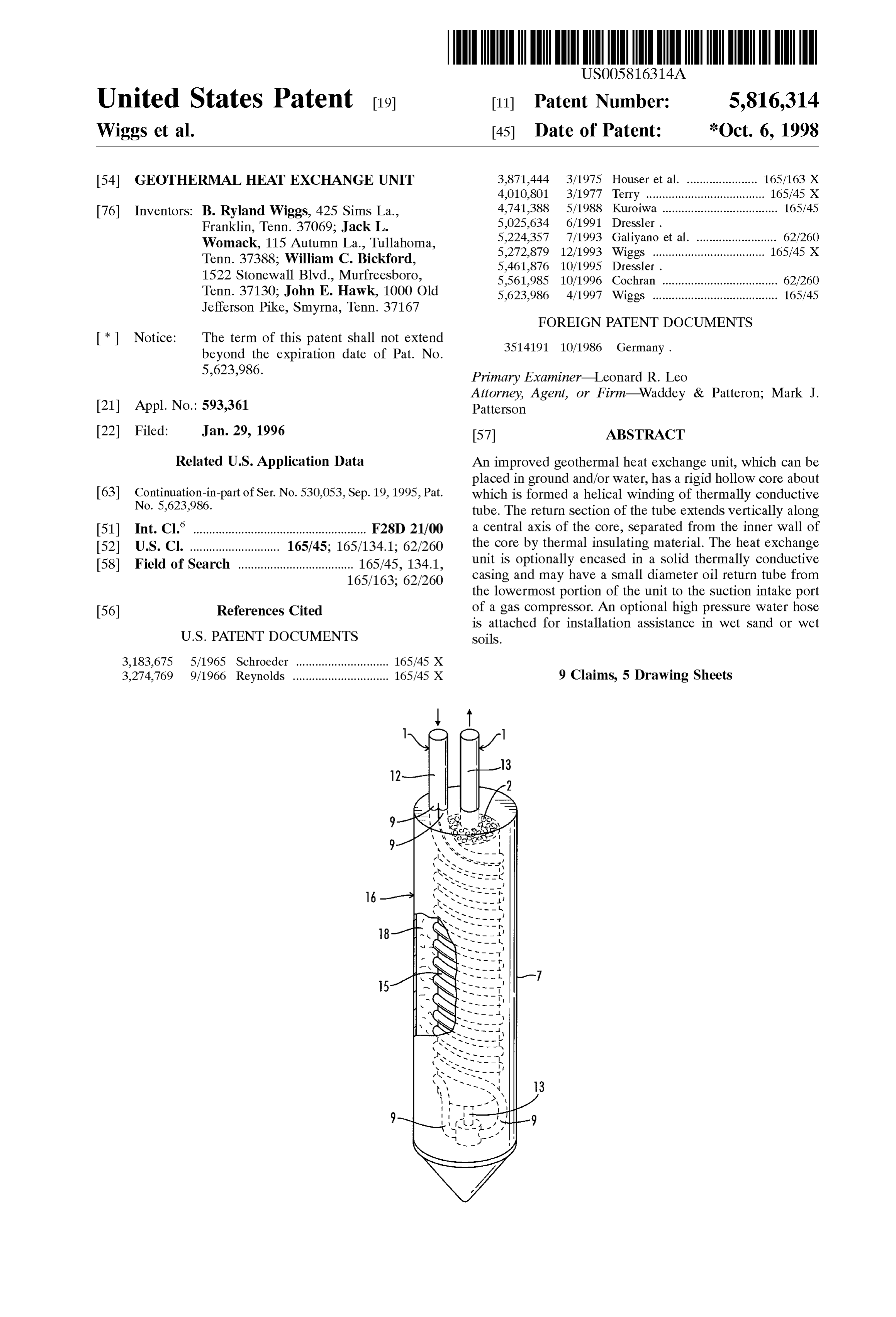
S 6 compressor lubricant oil return in a direct expansion appli description is not intended in a limiting Sense, and is made cation; to provide alternative means for heat eXchange Solely for the purpose of illustrating the general principles of within the thermally conductive casing Surrounding the the invention. The various features and advantages of the thermally conductive tubing, to provide means for easily and present invention may be more readily understood with efficiently installing the Wiggs heat eXchange units in wet reference to the following detailed description taken in Sand and/or wet Soil; and to provide a highly heat conductive conjunction with the accompanying drawings. means for installing the Wiggs heat eXchange unit in ground Referring now to the drawings in detail, where like holes with diameters larger than the diameter of the unit numerals refer to like parts or elements, there is shown in itself, where installations are in rock or Solid Soils. FIG. 1 a first embodiment of the invention which utilizes a Accomplishment of each of these objectives will result in conventional elongated U-shaped, fluid transfer, ground heat an increase in efficiency and/or in a decrease in System eXchange tube 1, as commonly utilized for Vertical or Slanted installation costs, all contributing toward enhanced returns closed loop geothermal heating/cooling installations. The on initial purchase and installation costs of geothermal tube 1 will have a fluid supply section 12 and a fluid return heating/cooling Systems. Section 13. Because U-shaped closed loops are commonly
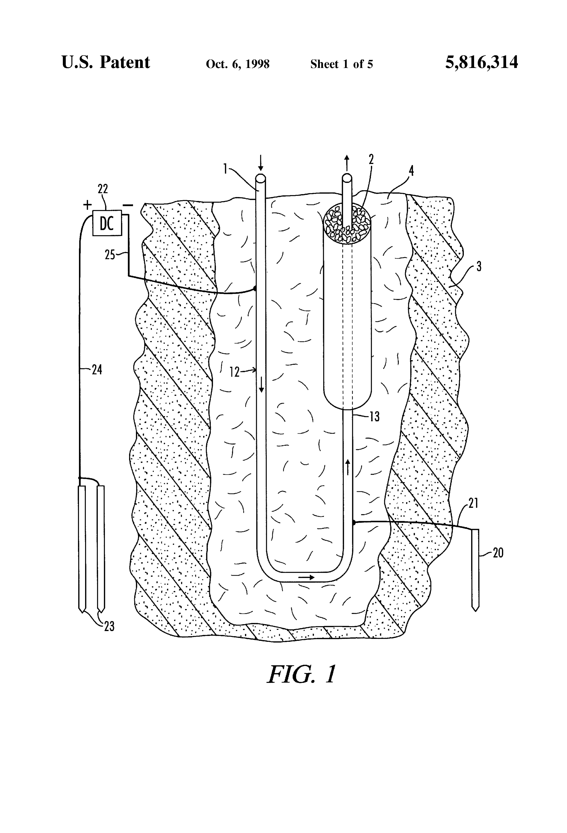
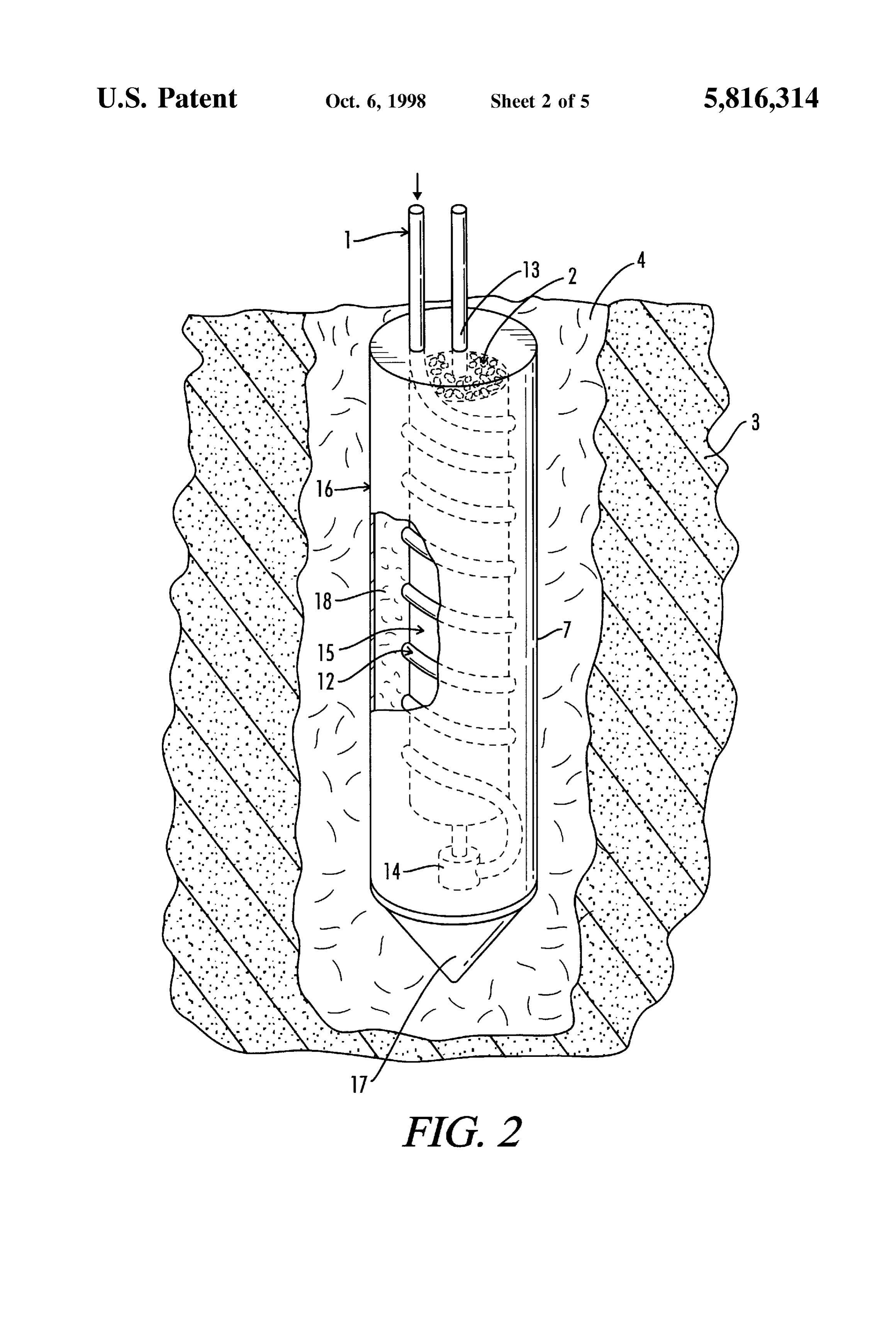
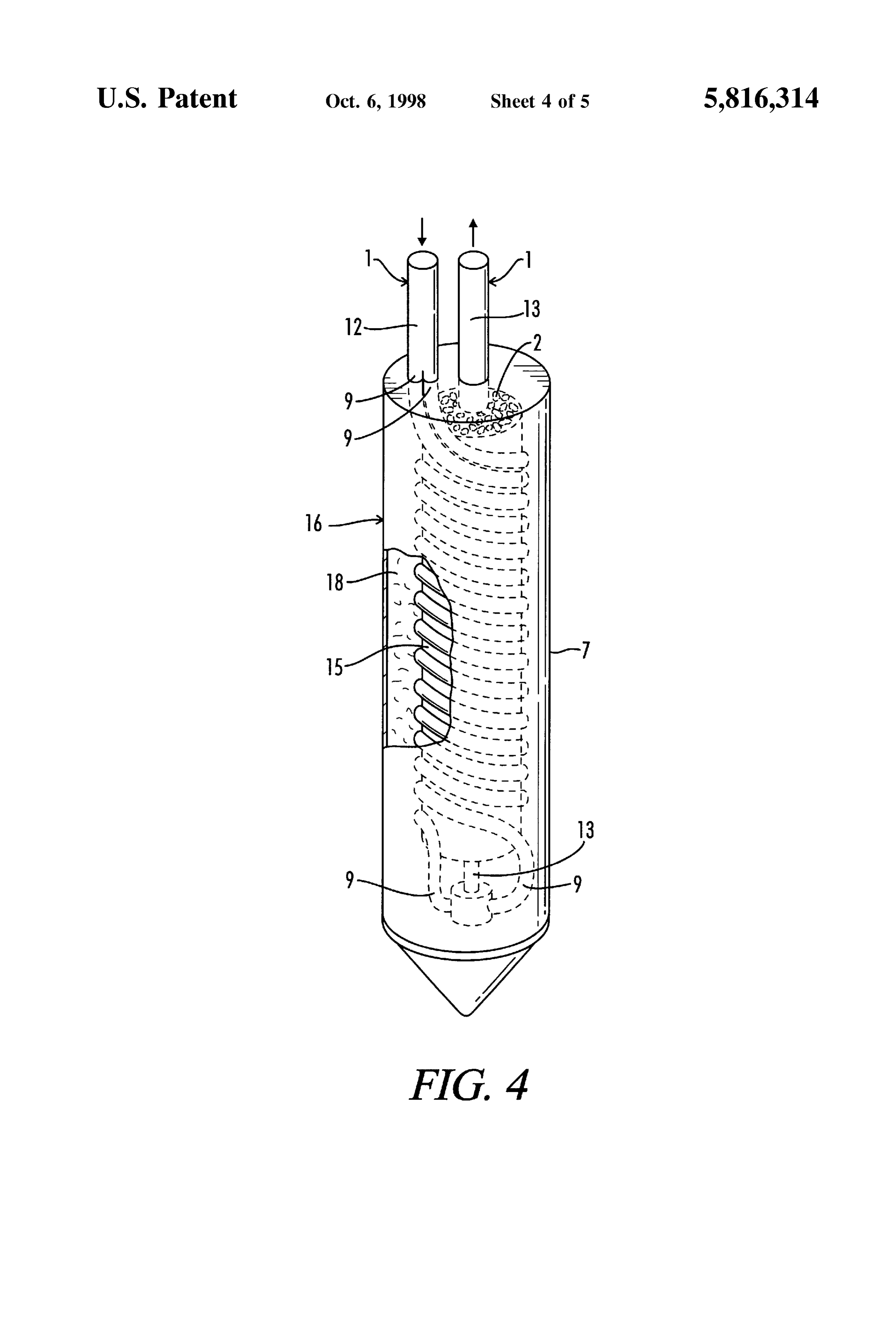
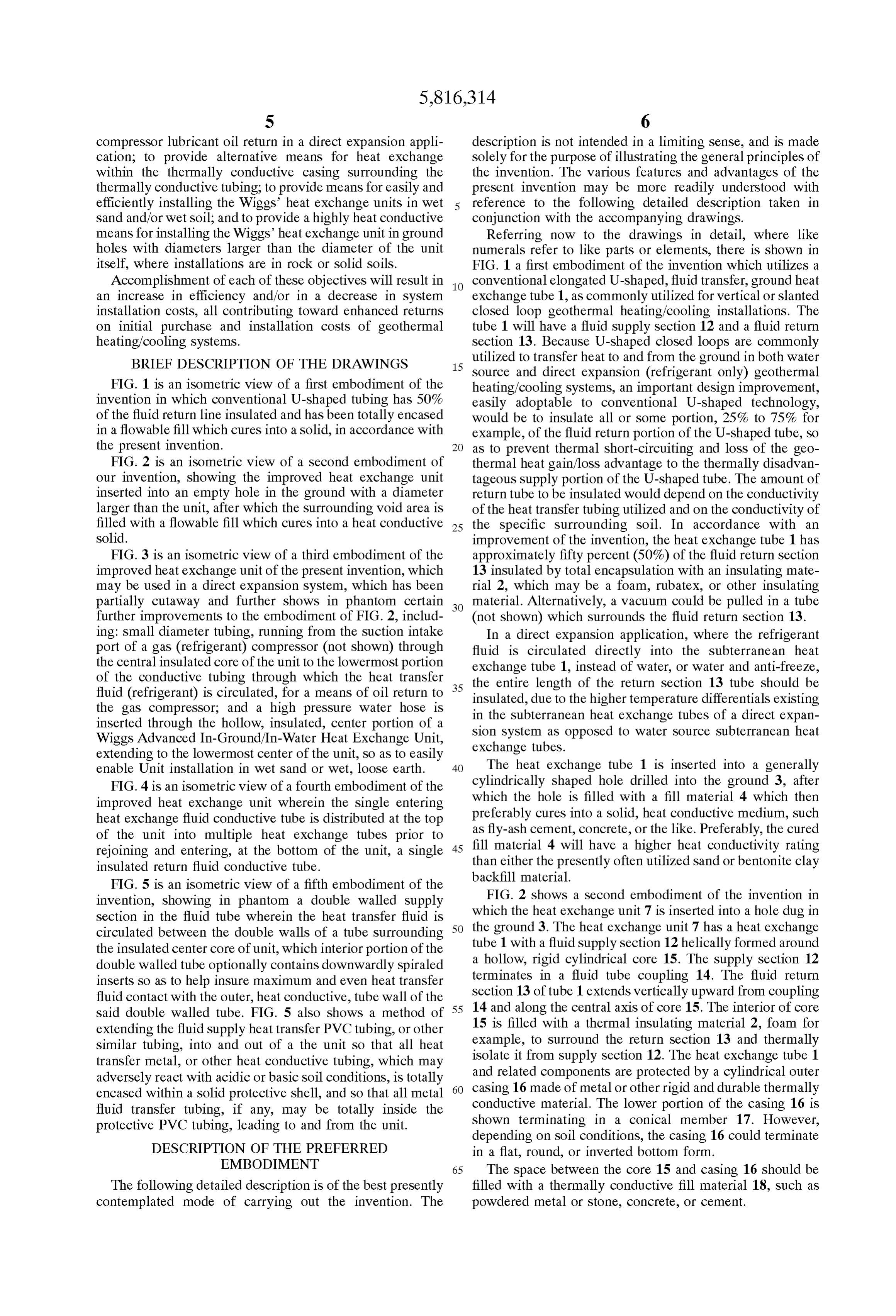
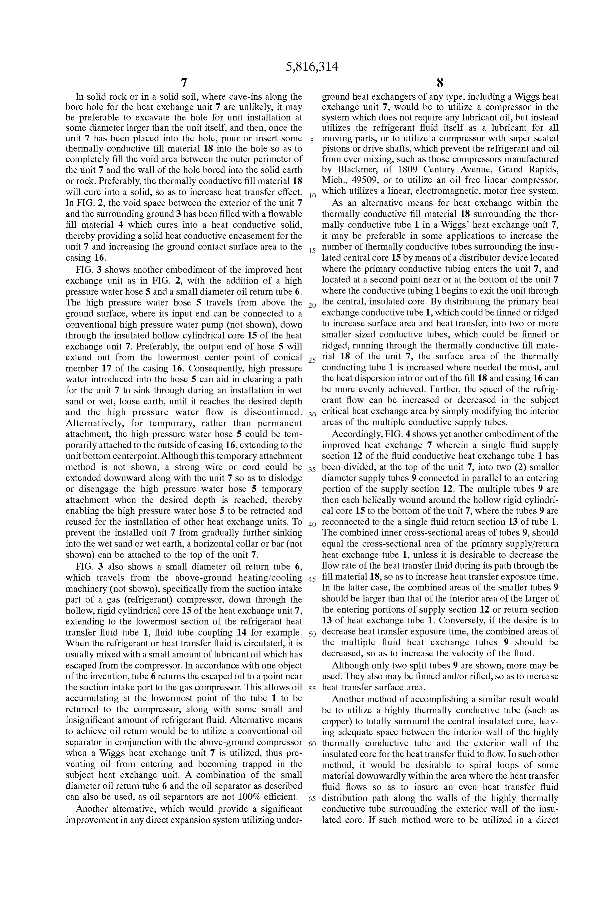
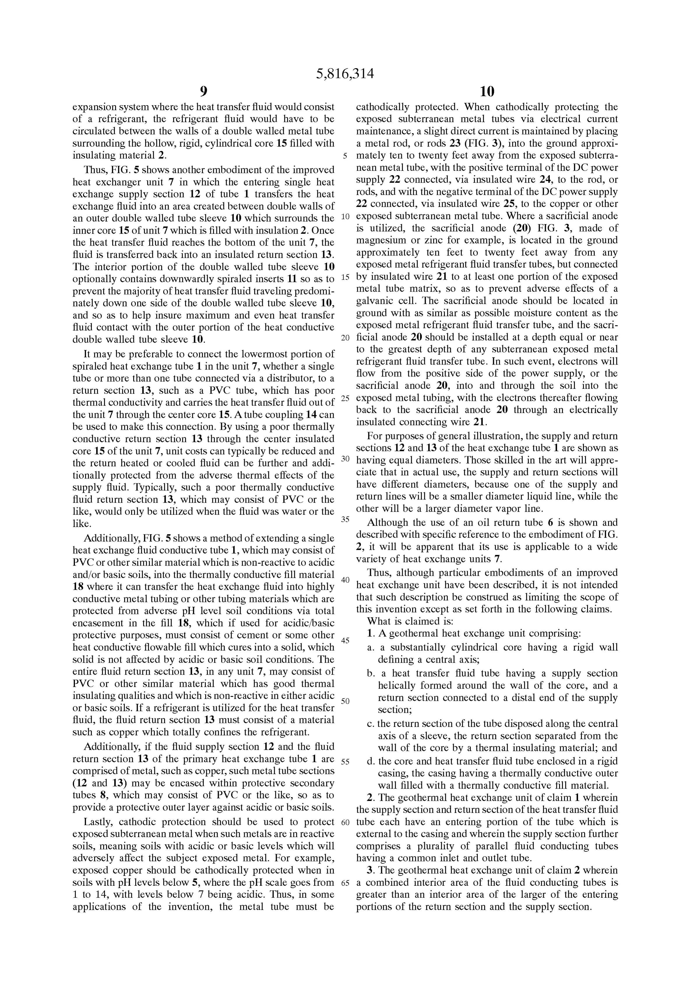
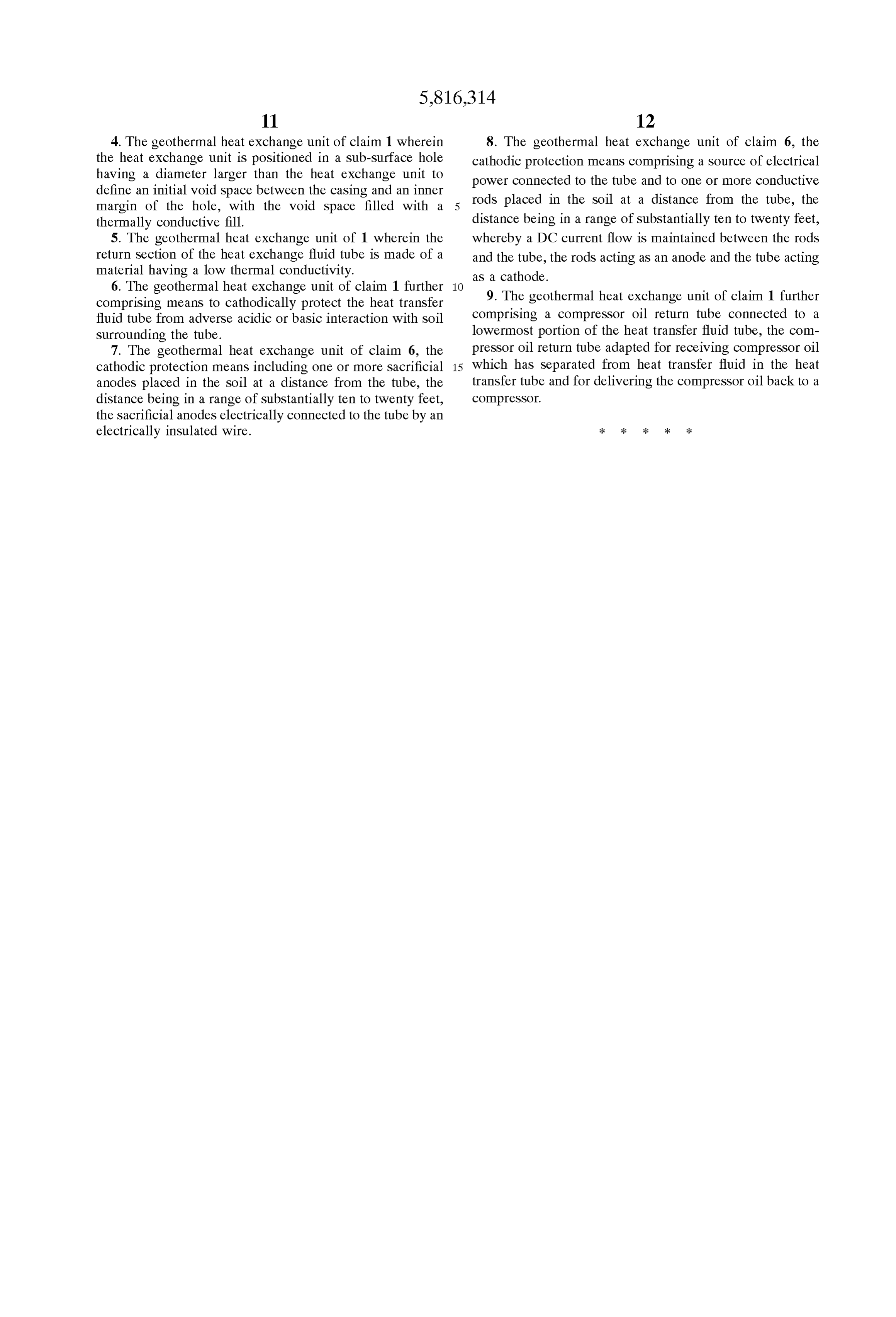
BRIEF DESCRIPTION OF THE DRAWINGS 15
utilized to transfer heat to and from the ground in both water
Source and direct expansion (refrigerant only) geothermal
FIG. 1 is an isometric view of a first embodiment of the heating/cooling Systems, an important design improvement, invention in which conventional U-shaped tubing has 50% easily adoptable to conventional U-shaped technology, of the fluid return line insulated and has been totally encased would be to insulate all or some portion, 25% to 75% for in a flowable fill which cures into a solid, in accordance with example, of the fluid return portion of the U-shaped tube, So the present invention. as to prevent thermal short-circuiting and loSS of the geo FIG. 2 is an isometric view of a second embodiment of thermal heat gain/loSS advantage to the thermally disadvan our invention, showing the improved heat eXchange unit tageous Supply portion of the U-shaped tube. The amount of inserted into an empty hole in the ground with a diameter return tube to be insulated would depend on the conductivity larger than the unit, after which the Surrounding void area is of the heat transfer tubing utilized and on the conductivity of filled with a flowable fill which cures into a heat conductive 25 the Specific Surrounding Soil. In accordance with an Solid. improvement of the invention, the heat eXchange tube 1 has FIG. 3 is an isometric view of a third embodiment of the approximately fifty percent (50%) of the fluid return section improved heat eXchange unit of the present invention, which 13 insulated by total encapsulation with an insulating mate may be used in a direct expansion System, which has been rial 2, which may be a foam, rubatex, or other insulating partially cutaway and further shows in phantom certain material. Alternatively, a vacuum could be pulled in a tube further improvements to the embodiment of FIG. 2, includ (not shown) which surrounds the fluid return section 13. ing: Small diameter tubing, running from the Suction intake In a direct expansion application, where the refrigerant port of a gas (refrigerant) compressor (not shown) through fluid is circulated directly into the Subterranean heat the central insulated core of the unit to the lowermost portion eXchange tube 1, instead of water, or water and anti-freeze, of the conductive tubing through which the heat transfer fluid (refrigerant) is circulated, for a means of oil return to 35 the entire length of the return section 13 tube should be insulated, due to the higher temperature differentials existing the gas compressor, and a high pressure water hose is in the Subterranean heat eXchange tubes of a direct expan inserted through the hollow, insulated, center portion of a Sion System as opposed to water Source Subterranean heat Wiggs Advanced In-Ground/In-Water Heat Exchange Unit, eXchange tubes.
extending to the lowermost center of the unit, So as to easily enable Unit installation in Wet Sand or wet, loose earth. 40 The heat eXchange tube 1 is inserted into a generally FIG. 4 is an isometric view of a fourth embodiment of the cylindrically shaped hole drilled into the ground 3, after improved heat eXchange unit wherein the Single entering which the hole is filled with a fill material 4 which then heat eXchange fluid conductive tube is distributed at the top preferably cures into a Solid, heat conductive medium, Such of the unit into multiple heat eXchange tubes prior to as fly-ash cement, concrete, or the like. Preferably, the cured rejoining and entering, at the bottom of the unit, a single 45 fill material 4 will have a higher heat conductivity rating insulated return fluid conductive tube. than either the presently often utilized Sand or bentonite clay FIG. 5 is an isometric view of a fifth embodiment of the backfill material.
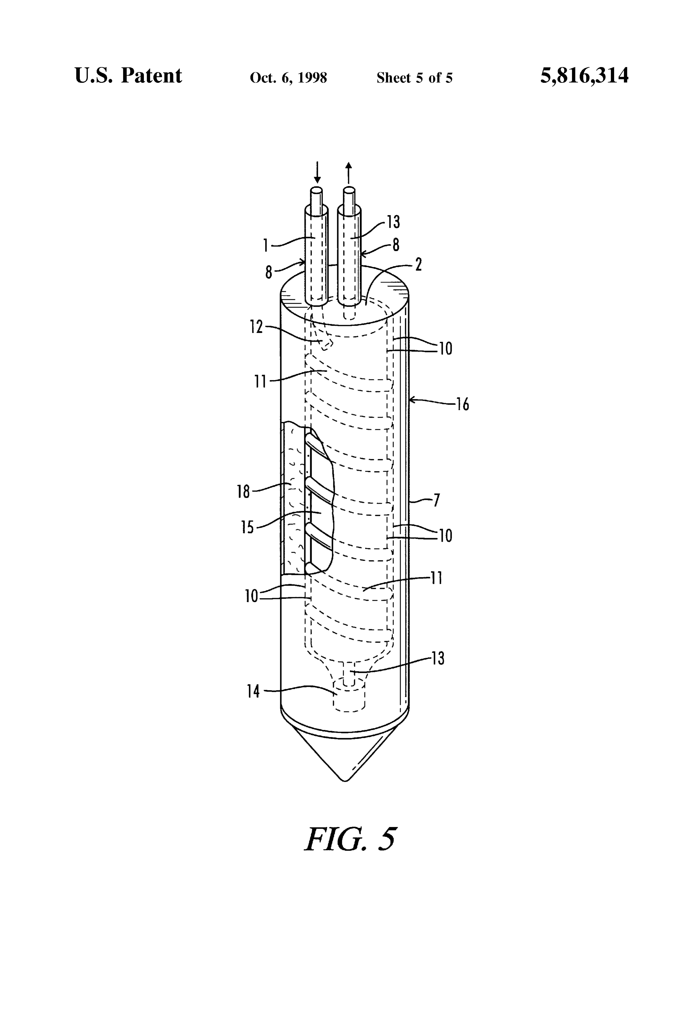
invention, showing in phantom a double walled Supply FIG. 2 shows a second embodiment of the invention in Section in the fluid tube wherein the heat transfer fluid is which the heat eXchange unit 7 is inserted into a hole dug in circulated between the double walls of a tube surrounding 50 the ground 3. The heat eXchange unit 7 has a heat eXchange the insulated center core of unit, which interior portion of the tube 1 with a fluid supply section 12 helically formed around double walled tube optionally contains downwardly spiraled a hollow, rigid cylindrical core 15. The Supply section 12 inserts So as to help insure maximum and even heat transfer terminates section 13 in a fluid tube coupling 14. The fluid return of tube 1 extends vertically upward from coupling fluid contact with the outer, heat conductive, tube wall of the said double walled tube. FIG. 5 also shows a method of 55 14 and along the central axis of core 15. The interior of core extending the fluid supply heat transfer PVC tubing, or other 15 is filled with a thermal insulating material 2, foam for Similar tubing, into and out of a the unit So that all heat example, to Surround the return Section 13 and thermally transfer metal, or other heat conductive tubing, which may isolate it from Supply Section 12. The heat eXchange tube 1 adversely react with acidic or basic Soil conditions, is totally 60 and related components are protected by a cylindrical outer encased within a Solid protective shell, and So that all metal casing 16 made of metal or other rigid and durable thermally fluid transfer tubing, if any, may be totally inside the conductive material. The lower portion of the casing 16 is protective PVC tubing, leading to and from the unit. shown terminating in a conical member 17. However, depending on Soil conditions, the casing 16 could terminate
DESCRIPTION OF THE PREFERRED in a flat, round, or inverted bottom form. EMBODIMENT 65 The space between the core 15 and casing 16 should be The following detailed description is of the best presently filled with a thermally conductive fill material 18, such as contemplated mode of carrying out the invention. The powdered metal or Stone, concrete, or cement.
Page 10
In Solid rock or in a Solid Soil, where cave-ins along the ground heat eXchangers of any type, including a Wiggs heat bore hole for the heat eXchange unit 7 are unlikely, it may eXchange unit 7, would be to utilize a compressor in the be preferable to excavate the hole for unit installation at System which does not require any lubricant oil, but instead Some diameter larger than the unit itself, and then, once the utilizes the refrigerant fluid itself as a lubricant for all unit 7 has been placed into the hole, pour or insert Some moving parts, or to utilize a compressor with Super Sealed thermally conductive fill material 18 into the hole so as to pistons or drive shafts, which prevent the refrigerant and oil completely fill the void area between the outer perimeter of from ever mixing, Such as those compressors manufactured the unit 7 and the wall of the hole bored into the Solid earth by Blackmer, of 1809 Century Avenue, Grand Rapids, or rock. Preferably, the thermally conductive fill material 18 Mich., 49509, or to utilize an oil free linear compressor, will cure into a Solid, So as to increase heat transfer effect. which utilizes a linear, electromagnetic, motor free System. In FIG. 2, the void space between the exterior of the unit 7 AS an alternative means for heat eXchange within the and the surrounding ground 3 has been filled with a flowable thermally conductive fill material 18 surrounding the ther fill material 4 which cures into a heat conductive Solid, mally conductive tube 1 in a Wiggs heat eXchange unit 7, thereby providing a Solid heat conductive encasement for the it may be preferable in Some applications to increase the unit 7 and increasing the ground contact Surface area to the 15 number of thermally conductive tubes Surrounding the insu casing 16. lated central core 15 by means of a distributor device located FIG. 3 shows another embodiment of the improved heat where the primary conductive tubing enters the unit 7, and eXchange unit as in FIG. 2, with the addition of a high located at a second point near or at the bottom of the unit 7 pressure water hose 5 and a small diameter oil return tube 6. where the conductive tubing 1 begins to exit the unit through The high pressure water hose 5 travels from above the the central, insulated core. By distributing the primary heat ground Surface, where its input end can be connected to a eXchange conductive tube 1, which could be finned or ridged conventional high pressure water pump (not shown), down to increase Surface area and heat transfer, into two or more through the insulated hollow cylindrical core 15 of the heat Smaller sized conductive tubes, which could be finned or exchange unit 7. Preferably, the output end of hose 5 will ridged, running through the thermally conductive fill mate extend out from the lowermost center point of conical 25 rial 18 of the unit 7, the surface area of the thermally member 17 of the casing 16. Consequently, high preSSure conducting tube 1 is increased where needed the most, and water introduced into the hose 5 can aid in clearing a path the heat dispersion into or out of the fill 18 and casing 16 can for the unit 7 to Sink through during an installation in wet be more evenly achieved. Further, the speed of the refrig Sand or wet, loose earth, until it reaches the desired depth erant flow can be increased or decreased in the Subject and the high pressure water flow is discontinued. critical heat eXchange area by Simply modifying the interior Alternatively, for temporary, rather than permanent areas of the multiple conductive Supply tubes. attachment, the high pressure water hose 5 could be tem Accordingly, FIG. 4 shows yet another embodiment of the porarily attached to the outside of casing 16, extending to the improved heat exchange 7 wherein a single fluid Supply unit bottom centerpoint. Although this temporary attachment Section 12 of the fluid conductive heat eXchange tube 1 has method is not shown, a strong wire or cord could be 35 been divided, at the top of the unit 7, into two (2) Smaller extended downward along with the unit 7 So as to dislodge diameter Supply tubes 9 connected in parallel to an entering or disengage the high pressure water hose 5 temporary portion of the Supply section 12. The multiple tubes 9 are attachment when the desired depth is reached, thereby then each helically wound around the hollow rigid cylindri enabling the high pressure water hose 5 to be retracted and cal core 15 to the bottom of the unit 7, where the tubes 9 are reused for the installation of other heat eXchange units. To 40 reconnected to the a single fluid return section 13 of tube 1. prevent the installed unit 7 from gradually further Sinking The combined inner cross-sectional areas of tubes 9, should into the wet sand or wet earth, a horizontal collar or bar (not equal the cross-sectional area of the primary Supply/return shown) can be attached to the top of the unit 7. heat eXchange tube 1, unless it is desirable to decrease the FIG. 3 also shows a small diameter oil return tube 6, flow rate of the heat transfer fluid during its path through the which travels from the above-ground heating/cooling 45 fill material 18, So as to increase heat transfer exposure time. machinery (not shown), Specifically from the Suction intake In the latter case, the combined areas of the Smaller tubes 9 part of a gas (refrigerant) compressor, down through the should be larger than that of the interior area of the larger of hollow, rigid cylindrical core 15 of the heat exchange unit 7, the entering portions of Supply Section 12 or return Section extending to the lowermost Section of the refrigerant heat 13 of heat exchange tube 1. Conversely, if the desire is to transfer fluid tube 1, fluid tube coupling 14 for example. 50 decrease heat transfer exposure time, the combined areas of When the refrigerant or heat transfer fluid is circulated, it is the multiple fluid heat exchange tubes 9 should be usually mixed with a small amount of lubricant oil which has decreased, So as to increase the Velocity of the fluid. escaped from the compressor. In accordance with one object Although only two split tubes 9 are shown, more may be of the invention, tube 6 returns the escaped oil to a point near used. They also may be finned and/or rifled, So as to increase the Suction intake port to the gas compressor. This allows oil 55 heat transfer Surface area.
accumulating at the lowermost point of the tube 1 to be Another method of accomplishing a similar result would returned to the compressor, along with Some Small and be to utilize a highly thermally conductive tube (such as insignificant amount of refrigerant fluid. Alternative means copper) to totally Surround the central insulated core, leav to achieve oil return would be to utilize a conventional oil ing adequate Space between the interior wall of the highly Separator in conjunction with the above-ground compressor 60 thermally conductive tube and the exterior wall of the when a Wiggs heat eXchange unit 7 is utilized, thus pre insulated core for the heat transfer fluid to flow. In Such other venting oil from entering and becoming trapped in the method, it would be desirable to spiral loops of some Subject heat eXchange unit. A combination of the Small material downwardly within the area where the heat transfer diameter oil return tube 6 and the oil Separator as described fluid flows so as to insure an even heat transfer fluid can also be used, as oil Separators are not 100% efficient. 65 distribution path along the walls of the highly thermally Another alternative, which would provide a significant conductive tube Surrounding the exterior wall of the insu improvement in any direct expansion System utilizing under lated core. If Such method were to be utilized in a direct
Page 11
expansion System where the heat transfer fluid would consist cathodically protected. When cathodically protecting the of a refrigerant, the refrigerant fluid would have to be exposed Subterranean metal tubes via electrical current circulated between the walls of a double walled metal tube maintenance, a slight direct current is maintained by placing surrounding the hollow, rigid, cylindrical core 15 filled with a metal rod, or rods 23 (FIG. 3), into the ground approxi insulating material 2. mately ten to twenty feet away from the exposed Subterra Thus, FIG. 5 shows another embodiment of the improved nean metal tube, with the positive terminal of the DC power heat eXchanger unit 7 in which the entering Single heat Supply 22 connected, via insulated wire 24, to the rod, or eXchange Supply Section 12 of tube 1 transferS the heat rods, and with the negative terminal of the DC power Supply eXchange fluid into an area created between double walls of 22 connected, via insulated wire 25, to the copper or other an outer double walled tube sleeve 10 which Surrounds the exposed Subterranean metal tube. Where a Sacrificial anode inner core 15 of unit 7 which is filled with insulation 2. Once is utilized, the sacrificial anode (20) FIG. 3, made of the heat transfer fluid reaches the bottom of the unit 7, the magnesium or Zinc for example, is located in the ground fluid is transferred back into an insulated return section 13. approximately ten feet to twenty feet away from any The interior portion of the double walled tube sleeve 10 exposed metal refrigerant fluid transfer tubes, but connected optionally contains downwardly spiraled inserts 11 So as to 15 by insulated wire 21 to at least one portion of the exposed prevent the majority of heat transfer fluid traveling predomi metal tube matrix, So as to prevent adverse effects of a nately down one side of the double walled tube sleeve 10, galvanic cell. The Sacrificial anode should be located in and So as to help insure maximum and even heat transfer ground with as Similar as possible moisture content as the fluid contact with the outer portion of the heat conductive exposed metal refrigerant fluid transfer tube, and the Sacri double walled tube sleeve 10. ficial anode 20 should be installed at a depth equal or near It may be preferable to connect the lowermost portion of to the greatest depth of any Subterranean exposed metal Spiraled heat eXchange tube 1 in the unit 7, whether a single refrigerant fluid transfer tube. In such event, electrons will flow from the positive side of the power supply, or the tube or more than one tube connected via a distributor, to a return section 13, such as a PVC tube, which has poor 25 Sacrificial anode 20, into and through the Soil into the exposed metal tubing, with the electrons thereafter flowing thermal conductivity and carries the heat transfer fluid out of back to the Sacrificial anode 20 through an electrically the unit 7 through the center core 15. A tube coupling 14 can be used to make this connection. By using a poor thermally insulated connecting wire 21.
conductive return Section 13 through the center insulated For purposes of general illustration, the Supply and return core 15 of the unit 7, unit costs can typically be reduced and Sections 12 and 13 of the heat eXchange tube 1 are shown as the return heated or cooled fluid can be further and addi having equal diameters. Those skilled in the art will appre tionally protected from the adverse thermal effects of the ciate that in actual use, the Supply and return Sections will Supply fluid. Typically, Such a poor thermally conductive have different diameters, because one of the Supply and fluid return section 13, which may consist of PVC or the return lines will be a smaller diameter liquid line, while the like, would only be utilized when the fluid was water or the 35 other will be a larger diameter vapor line. like. Although the use of an oil return tube 6 is shown and Additionally, FIG. 5 shows a method of extending a single described with specific reference to the embodiment of FIG. heat eXchange fluid conductive tube 1, which may consist of 2, it will be apparent that its use is applicable to a wide PVC or other similar material which is non-reactive to acidic variety of heat eXchange units 7. and/or basic Soils, into the thermally conductive fill material 40 Thus, although particular embodiments of an improved 18 where it can transfer the heat exchange fluid into highly heat eXchange unit have been described, it is not intended conductive metal tubing or other tubing materials which are that Such description be construed as limiting the Scope of protected from adverse pH level soil conditions via total this invention except as Set forth in the following claims. encasement in the fill 18, which if used for acidic/basic What is claimed is:
protective purposes, must consist of cement or Some other 45 1. A geothermal heat eXchange unit comprising: heat conductive flowable fill which cures into a Solid, which a. a Substantially cylindrical core having a rigid wall solid is not affected by acidic or basic soil conditions. The defining a central axis, entire fluid return Section 13, in any unit 7, may consist of b. a heat transfer fluid tube having a Supply Section PVC or other similar material which has good thermal helically formed around the wall of the core, and a insulating qualities and which is non-reactive in either acidic 50 return Section connected to a distal end of the Supply or basic Soils. If a refrigerant is utilized for the heat transfer Section;
fluid, the fluid return section 13 must consist of a material c. the return Section of the tube disposed along the central Such as copper which totally confines the refrigerant. axis of a sleeve, the return Section Separated from the Additionally, if the fluid supply section 12 and the fluid wall of the core by a thermal insulating material; and return Section 13 of the primary heat eXchange tube 1 are 55 d. the core and heat transfer fluid tube enclosed in a rigid comprised of metal, Such as copper, Such metal tube Sections casing, the casing having a thermally conductive outer (12 and 13) may be encased within protective Secondary wall filled with a thermally conductive fill material. tubes 8, which may consist of PVC or the like, so as to 2. The geothermal heat eXchange unit of claim 1 wherein provide a protective outer layer against acidic or basic Soils. the Supply Section and return Section of the heat transfer fluid Lastly, cathodic protection should be used to protect 60 tube each have an entering portion of the tube which is exposed Subterranean metal when Such metals are in reactive external to the casing and wherein the Supply Section further Soils, meaning Soils with acidic or basic levels which will comprises a plurality of parallel fluid conducting tubes adversely affect the Subject exposed metal. For example, having a common inlet and outlet tube.
exposed copper should be cathodically protected when in 3. The geothermal heat eXchange unit of claim 2 wherein soils with pH levels below 5, where the pH scale goes from 65 a combined interior area of the fluid conducting tubes is 1 to 14, with levels below 7 being acidic. Thus, in some greater than an interior area of the larger of the entering applications of the invention, the metal tube must be portions of the return Section and the Supply Section.
Page 12
4. The geothermal heat eXchange unit of claim 1 wherein 8. The geothermal heat eXchange unit of claim 6, the the heat eXchange unit is positioned in a Sub-Surface hole cathodic protection means comprising a Source of electrical having a diameter larger than the heat eXchange unit to power connected to the tube and to one or more conductive define an initial void space between the casing and an inner rods placed in the Soil at a distance from the tube, the margin of the hole, with the void space filled with a thermally conductive fill. distance being in a range of Substantially ten to twenty feet, 5. The geothermal heat exchange unit of 1 wherein the whereby a DC current flow is maintained between the rods return Section of the heat eXchange fluid tube is made of a and the tube, the rods acting as an anode and the tube acting material having a low thermal conductivity. as a cathode.
6. The geothermal heat eXchange unit of claim 1 further 9. The geothermal heat exchange unit of claim 1 further comprising means to cathodically protect the heat transfer fluid tube from adverse acidic or basic interaction with soil comprising a compressor oil return tube connected to a Surrounding the tube. lowermost portion of the heat transfer fluid tube, the com 7. The geothermal heat eXchange unit of claim 6, the pressor oil return tube adapted for receiving compressor oil cathodic protection means including one or more Sacrificial 15 which has separated from heat transfer fluid in the heat anodes placed in the Soil at a distance from the tube, the transfer tube and for delivering the compressor oil back to a distance being in a range of Substantially ten to twenty feet, compressor.
the Sacrificial anodes electrically connected to the tube by an electrically insulated wire.
Provenance
- Collection
- Cited prior art
- Original PDF
- patentimages.storage.googleapis.com →
- Filed
- 1996-01-29
- Pages
- 12
- Method
- pdftotext (the PDF's own text layer) + pdftoppm 300dpi page scans
- Source
- Google Patents bibliographic record
- Granted
- 1998-10-06
- Inventors
- B. Ryland Wiggs; Jack L. Womack; William C. Bickford; John E. Hawk; Geothermal Heat Pumps Inc
- Transcribed from
- patentimages.storage.googleapis.com →