patent · US5224357
Modular tube bundle heat exchanger and geothermal heat pump system
6 July 1993
Page 1 — bibliographic record
United States Patent (19) 11 Patent Number: 5,224,357 Galiyano et al. - 45 Date of Patent: Jul. 6, 1993 54 MODULAR TUBE BUNDLE HEAT Primary Examiner-Henry A. Bennet EXCHANGER AND GEOTHERMAL, HEAT Assistant Examiner-William C. Doerrier PUMP SYSTEM Attorney, Agent, or Firm-Eckert, Seamans, Cherin & Meliott (75) Inventors: Mike P. Galiyano, Wyomissing Hills;
Mark J. Galiyano, Sinking Spring: B. 57 ABSTRACT
Ryland Wiggs; Jeffery T. Aspacher, A geothermal heat exchanger having modular tube both of Bethlehem, all of Pa. bundles is provided in a novel heat pump system. The (73) Assignee: United States Power Corporation, modular tube bundles are particularly adapted to be Allentown, Pa. placed within a narrow excavation in the ground, such 21 Appl. No.: 725,962 as a trench excavated using a backhoe bucket, which trench can be V-shaped. A heat resistant soaker hose is 22 Filed: Jul. 5, 1991 disposed above or about the rectangular tube bundles. (51) Int. Cl. .............................................. F28D 21/00 The soaker hose is coupled to a water source and has a 52) U.S. C. ......................................... 62/260; 165/45 number of apertures for leaching water to the soil sur 58 Field of Search ................. 62/260; 165/45, 45 H; rounding the tube bundles for dampening the soil 418/55.6 around the tubes and providing better thermal heat transfer and compaction. Individual tubes of the tube 56) References Cited bundles can be made rifled or finned for better heat
spiral scroll fins is provided rather than a reciprocating 654,264 7/1900 Lueder et al. ........................ 62/260 piston compressor. The scroll compressor, unlike a 2,554,661 5/1951 Clancy .................................. 62/260 reciprocating compressor, can efficiently pump fluid in 3,601, 186 8/1971 Smith et al. ........................... 165/45 a liquid state, will start against a high differential pres 4,058,982 11/1977 Wright .............................. 62A260 X 4,277,946 7/1981 Bottum ............. ... 62/235.1 sure, and provides more suction for oil return from the 4,332,535 6/1982 Terauchi et al. . ... 418/55.6 ground coils to the compressor. Corrosion of the in 4,382,370 5/1983 Suefuji et al. ... ... 62/324.1 ground preferably copper heat exchanger tubes is pre 4,383,419 5/1983 Bottum ............. ... 62/238.6 vented by a sacrificial anode cathodic protection sys 4,648,814 3/1987 Shibayashi. ... 418/55.6 tem. A microprocessor coupled to a variable speed 4,688,717 8/1987 Jungwirth ... ... 237A2 B compressor controls the system and the rate of refriger 4,741,388 5/1988 Kuroiwa ............................... 165/45 ant flow. An oil separator at the outlet of the compres 4,753,285 6/1988 Rawlings .............................. 165/45 sor discharges in a closed loop at the inlet of the con
4,860,544 8/1989 Krieg et al. .............. ... 62/260 pressor and eliminates oil from the heat exchanger sec 4,995,502 2/1991 Geppelt et al....... 165/45 tion of the refrigerant flow path. 5,025,634 6/1991 Dressier ........... ... 62/74 5,054,541 10/1991 Tripp ..................................... 165/45 26 Claims, 5 Drawing Sheets
Page 2
Drawing sheet — no readable text.
Page 3
at Fris reck2 2x262EEiSN2 /VY.,
-CE- II --------. still---t = c- - LTTT -4---4------. T.R.E.S.TH THE-T E.
III, III IIHE.E.E.
ESI I ILSE.
WJEEE
Page 4
Drawing sheet — no readable text.
Page 5
Drawing sheet — no readable text.
Page 6
Drawing sheet — no readable text.
Page 7
arrangements, which might define a buried U-bend, are
MODULAR TUBE BUNDLE HEAT EXCHANGER expensive and difficult to install, in part due to the ne AND GEOTHERMAL, HEAT PUMP SYSTEM cessity of forming deep vertical holes in the ground.
Equipment to accomplish such boring is typically com
BACKGROUND OF THE INVENTION 5 plex and expensive. Such holes have a tendency to cave 1. Field of the Invention in during or after the excavation process. Additionally, This invention relates to the field of heat pump sys accomplishing oil return to the compressor is difficult, tems and in particular to ground source heat pump especially when the system is designed to operate in systems. The invention provides a system having modu O both the heating and cooling mode. On the other hand, lar in-ground heat exchangers suitable for simple instal vertically elongated arrangements define less of an ob lation in a trench, and particular compressor and circu struction to earth which is replaced after installation, lation features facilitating installation and operation of a which (at least at the heat exchanger) must be placed in heat pump system for heat transfer to and from the intimate contact with the refrigerant carrying means in earth. order to achieve good thermal coupling with the earth. 2. Prior Art. 5 A problem with vertical extensions is the tendency Heat pump systems are increasingly popular for effi for gas to rise upward through liquid. For example, if a cient heating and cooling of loads, for example as part segment of gas were disposed at the buried U-bend of a of a heating-ventilation-air conditioning (HVAC) sys vertically oriented pipe, it would tend to bubble up ten for buildings. Heat pump systems generally include through the liquid without pushing the liquid on heat exchangers thermally coupled to the load and to a 20 through the system. The gas would pass through the heat source or heat sink, the heat exchangers being liquid unable to push the liquid through the coils. The connected in a refrigerant or coolant loop which in liquid, as well as intermixed refrigerant and oil/lubri cludes a compressor and an expander. The compressor cant, would thus settle at the bottom of the coils, reduc raises the pressure (and therefore the temperature) of ing efficiency and/or resulting in compressor failure. the refrigerant and the expander lowers the pressure, 25 Arrangements which encompass a substantial hori producing a lower temperature in the refrigerant gas.
in heating a load, a "ground source' heat pump, zontal area, for example including horizontal or slanted in-ground pipes, require a large land area for installa which has the source/sink heat exchanger thermally tion. Whereas conductively coupled to the ground, can extract a virtu changer must betheburied array of pipes defining a heat ex deeply, the installer may have ally limitless supply of thermal energy from the earth to remove a huge quantity and transfer the energy, at higher temperature, to the and then must replace the of earth to place the pipes, earth over the pipes. The load. A heat pump cools a load by extracting thermal problem can be daunting when using multiple loops in a energy from the load and transferring it, at higher tem horizontally oriented pattern. Further, the use of hori perature, to the earth for dissipation therein. In this Zontal pipes typically result in refrigerant pipe cross manner the ground functions as either a heat sink or 35 overs, which may reduce efficiency. Existing heat source. Modern day heat pumps for HVAC sys water lines further complicate the installation. gas and tems are equipped with reversing features such as valves to arrange the flow of refrigerant so that they The choice of horizontal, vertical and slanted pipe may both heat and cool the load, as needed. runs is constrained in known ground source systems by A ground source heat pump requires a subterranean operational complications in addition to installation heat exchanger. While it is possible to use intermediate problems, especially in conjunction with the reciprocat heat exchangers for transferring heat through thermally ing piston type compressor which conventionally coupled fluid flow paths or the like, preferably the re drives the refrigerant flow in known heat pump sys frigerant or coolant is pumped through the pipes by the tems. Inasmuch as the ground heat exchanger must be compressor and serves directly as the carrier for con 45 buried, at least some vertically oriented pipe runs are veying the thermal energy to or from the ground. Thus, almost always needed. A notable problem is encoun extra heat transfer losses, such as those inherent in tered in that when an energy demand cycle is com ground water source systems, are avoided. The coolant pleted, the compressor which drives the flow of refrig is relatively heated by compression and cooled by ex erant shuts down pending a subsequent demand for pansion, leading to the respective heat exchangers, 50 energy transfer. As a result, a certain amount of refrig thereby raising the temperature of the hot side heat erant then passing through the subterranean pipes exchanger above the temperature of the load and lower looses its momentum and remains at low points in the ing the temperature of the cool side heat exchanger pipes where it cools and may condense. The compres below the temperature of the source, whereupon heat sor is generally designed for efficient pumping of refrig transfer occurs. Compression and expansion normally 55 erant in the gaseous state as opposed to liquid. When the include a change of state of the coolant between liquid compressor come on after an off cycle it may quickly and gaseous states. deplete the gaseous refrigerant upstream of the con The load heat exchanger is typically above ground pressor along the flow path, such that a low pressure and the ground heat exchanger is preferably well below condition is created at the input of the compressor. the surface of the ground. Connecting pipes for the Gaseous refrigerant in the circuit may also be trapped ground heat exchanger, and the pipes defined by the between quantities of liquid refrigerant even in a hori heat exchanger itself, can be horizontal, vertical or zontal arrangement. Moreover, the refrigerant has a slanted. A typical installation may include combinations certain inertia, particularly in the liquid phase. For these of these orientations, depending upon particular design reasons, the compressor may encounter substantial criteria. A number of potential problems, however, are 65 loading problems when starting up after an off cycle. encountered with each possible orientation of the con Heat pump systems typically include control features necting pipes as well as pipes included in the heat ex designed to prevent compressor damage due to over changer itself. For example, vertically oriented pipe loading. Most systems are designed to interpret a low
Page 8
pressure condition at the compressor input as an indica refrigeration loops for optimum heat exchange with the tion that insufficient refrigerant exists in the system to earth. The plurality of buried refrigeration loops in function properly. As a result, the compressor is auto Jungwirth necessarily complicates the excavating pro matically shut down when a low pressure condition is cess. It is necessary to bore a plurality of holes radially sensed in order to protect against failure of the compres outward from a central excavation site or to excavate sor due to absence of sufficient refrigerant. and later refill a substantial volume of earth. Further, A pressure problem is typically encountered with a this design solely operates in a heating mode. reciprocating compressor during regular on/off opera German Offeniegungsschrift 35 14 191 - Waterkotte tional cycles. To allow pressures to equalize during (Oct. 23, 1986) discloses a series of looped lines extend such periods, the prior art, such as U.S. Pat. No. 10 ing to and from a central manifold, specifically placed 5,025,634 - Dressler, resorts to the use of a bleeder hole to facilitate oil return to the compressor. in a pressure valve or wall. This may result in a slight U.S. Pat. No. 4,383,419 Bottum shows a heat pump system efficiency loss under certain operating condi heating system having a series of slightly slanted tubes tions. buried horizontally underground or located horizon A similar but more pronounced low pressure problem 15 tally under water. The refrigerant is used as the heat is encountered when a reversible system changes from a transfer fluid, with one manifold being disposed slightly heating mode to a cooling mode. Such a change inher below the other.
ently causes an imbalance in refrigerant capacity after U.S. Pat. No. 4,741,388 - Kuroiwa and U.S. Pat. No. reversing. This imbalance results from the much larger 4,277,946-Bottum depict vertically oriented heat ex volume capacity of the subterranean heat exchanger as changers requiring deep, vertical earth boring. Other compared to the volume capacity of the load heat ex designs known in the art such as Dressler include sys changer. tems with oversized accumulators so as to avoid slug When the operating cycle is reversed, additional time ging the compressor with liquid refrigerant, pressure must be allowed to manipulate the excess refrigerant equalization bleeder valves, storage and recycling de whereby the refrigerant can assume its appropriate 25 vices, self-adjusting refrigerant flow cooling valves and redistribution throughout the system in order to prop flow reversing valves. These special provisions are erly function in the reverse mode. During this redistri intended to remedy the above-mentioned coolant imbal bution period, a low pressure condition is created at the ance and pressure problems as well as the problem of input of the compressor. The relatively short time inter lubricant accumulation within the heat exchange tubes val allowed for the low pressure condition at the com 30 or connecting conduits.
pressor input, before shutdown to protect the compres It would be advantageous to resolve the foregoing sor, can be insufficient for a typical reciprocating piston problems without resort to various complications that type compressor to overcome the inertial resistance of each involve additional cost, installation steps, mainte stagnant refrigerant in the subterranean pipes and to nance and operational limitations. A heat pump based redistribute the refrigerant for operation in the reverse 35 heating/cooling system is therefore needed which is mode. As previously described, a continued low pres devoid of the inherent limitations and complications sure condition at the compressor input causes the com associated with present day systems of this nature, but is pressor to automatically prematurely shut down. at the same time robust and efficient. In particular, a A further problem with reciprocating piston com system not subject to pressure imbalances or deficien pressors in ground source heat pump systems results cies, and which is insensitive to accumulation of lubri from the typical fact that the compressor lubricant cating oil is needed. Preferably the system should have mixes and flows with the refrigerant. The compressor straightforward refrigerant and thermal flow paths in lubricant can, consequently, in the ground coils, ulti volving a minimum of elements. It is further desirable to mately accumulate resulting in compressor lubricant provide such a ground source heat pump heating/cool loss and failure. 45 ing system wherein the ground source heat exchanger Prior art attempts to circumvent the aforesaid prob or heat exchange tubing does not require disruption of a lems, including problems related to pressure, include large area of land or the forming and back filling of utilizing a bleeder hole in a valve/wall, and/or altering complex holes.
the heat pump design to orient the flow paths such that SUMMARY OF THE INVENTION low pressure conditions and obstructions are less likely 50 to occur, or cause fewer problems when they do occur. It is an object of this invention to provide a ground An example is to use a plurality of thermally coupled source heat exchanger which reduces the drilling and closed loop fluid circuits working in combination. A backfilling costs and problems associated with verti horizontally oriented refrigerant loop (i.e., with the cally oriented and slanted exchangers. compressor and expander), for example, can be ther 55 It is also an object of the invention to provide an mally coupled to a vertically disposed subterranean in-ground heat exchanger for use with a heat pump loop which simply circulates a heat exchange fluid based heating/cooling system which eliminates large through the heat exchanger. These solutions, besides land area requirements and excavation/backfill steps being complex and inefficient with respect to heat trans associated with horizontally arrayed, or substantially fer performance as well as installation as discussed horizontal heat exchangers.
above, tend to create new problems at least as serious as It is a further object of this invention to provide a those remedied. compressor mechanism for a ground source heat pump An example of a reversing cycle heating system for a system which eliminates refrigerant phase and compres building comprising a heat pump and heat exchanging sor oil problems, and substantially eliminates the need tubes is disclosed by U.S. Pat. No. 4,688,717 - Jung 65 for a refrigerant accumulator and/or an oversized re wirth. In Jungwirth, a central distributor communicates frigerant accumulator.
with a plurality of downwardly inclined heat exchang Another object of the invention is to provide a com ing tubes. Jungwirth emphasizes a multitude of buried pressor and in-ground heat exchanger arrangement
Page 9
which is insensitive to equalization problems encoun refrigerant in the tubes and the relatively constant tem tered with prior art reciprocating piston compressors. perature existing below ground, and prevents damage A further object of the invention is to provide over to the tubes and connections due to frost heaving, i.e., sized air handler coils for more efficient thermal trans periodic ground contraction and expansion as the fer of the extra heat generated via the subject in-ground ground alternately freezes and thaws. In warmer cli heat exchange coil design. mates wherein the heat pump is primarily used to cool Another object of the invention is to provide ca the load, the bundle can be placed closer to the surface. thodic protection to these unique in-ground metal Typically, the coils are placed so that the top layer of ground source exchange coils so as to prevent metal tubes is about four feet beneath the ground surface decay and so as to extend system life. O where the ground remains relatively cool and freezing In the accomplishment of these objects, arrays of rarely or never occurs. However, in extremely hot, modular, in-ground, heat exchangers are provided, each desert areas, the coils need to be buried deeper, so as to comprising tubes which are readily placed in trenches avoid the extreme usual ground surface heat. When formed simply using a backhoe or the like. Trenches installing in locations having a rock substrate, the coils formed could be U-shaped or, to avoid danger of trench 15 can be longer and buried shallower. collapse when installing coils, V-shaped. A reciprocat A plurality of individual tubes of each of one or more ing, or preferably a scroll type compressor drives flow heat exchanger units are coupled to a distributer for of refrigerant through the heat pump circuit. A scroll interfacing the tubes to the system conduits and com compressor is relatively insensitive to variations in the pressor. The distributer has a number of plates and phase and content of the material pumped whether 20 fittings adapted for interfacing to a plurality of tube liquid or gas. Consequently, large or oversized accumu ends whereby the refrigerant in the system is evenly lators, as provided by U.S. Pat. No. 5,025,634 - Dres distributed into the interfaced tubes and substantially sler, are unnecessary. The heat exchanger arrays in equal quantities of refrigerant are passed through each clude grouped, connected tubes which are vertically tube of the bundle during system operation. If a large placed in trench excavations along the sides of the 25 capacity is required, a plurality of interconnected, phys trenches. The coils have relatively small inner and outer ically separate bundles are linked serially or in parallel. diameters whereby they may be rolled-up prior to in In a parallel arrangement, a secondary distributor hav stallation. The tubes are rolled up prior to shipping and ing plates and apertures can be used to distribute equal unrolled at the time of installation and placed along the flows of refrigerant to each of the plurality of individual trench walls. Stakes having preformed coil attachment 30 bundles in the same manner that the distributor for a parts are evenly disposed intermittently along the given bundle distributes flow to the individual tubes. trench wall and hold the coils against the trench walls. A heat exchanging cartridge preferably comprises a The individual coils are held the requisite distance apart plurality of substantially parallel spaced tube members by the attachment parts of the stakes. Connections be for carrying refrigerant, defining a cartridge unit. The tween particular tubes are provided generally made at 35 cartridge is placed in the trench whereby the tubes are each tube end, for example using a header structure that disposed adjacent to the trench walls. It is advantageous defines successive paths of the refrigerant in alternating for improved heat transfer to provide the tubes with directions through the tubes in the array, the fluid tra either or both of rifled inner surfaces and finned outer versing each tube in the array. This provides substantial surfaces to increase the surface area of refrigerant to fluid-tube and tube-ground surface contact for maxi ground interaction.
mum thermal interaction between the refrigerant within In order to address operating problems of reciprocat the tube and the ground. The tubes are generally ing piston compressors of known heat pump systems, a aligned in a vertical plane relative to each other, with scroll type compressor is preferably employed. Recip one set of tubes on each respective side of its' subject rocating type compressors, as noted above, are gener trench. The tubes are held on the sides of the trench via 45 ally designed to pump gas as opposed to liquid, and can their affixation to stakes, which also serve to keep the be overloaded or overheated in the event of an uneven tubes spaced equidistant from one another so as to avoid refrigerant distribution throughout the system, as typi tube-to-tube contact, crossovers, and resulting ineffi cally occurs during the reversing process or shortly ciencies. thereafter. When the system seeks to achieve an even The modular bundle of tubes is particularly adapted 50 distribution of refrigerant in the required direction of to be placed in a simple earth excavation such as the pumping, a temporary low pressure condition exists at trough formed by a backhoe. For this reason, the tube the input to the compressor. The low pressure loading bundles are preferably placed along each side of a 2 foot conditions are not readily distinguishable from loading wide trench, corresponding to a standard width of a conditions due to critical system problems as might be backhoe bucket. The relatively short length and width 55 caused by blockage or loss of refrigerant. Control sys of the trenches for the subject copper coils allows this tems which sense pressure conditions, compressor load design's installation in small land areas and without ing and the like in a piston compressor system, and time major disruption to alternate land usage. out to shut down the compressor, may be necessary to Alternately, the tube configuration can be installed in avoid compressor damage, but too often shut down a V-shaped trench formed in the earth by appropriate during reversing operation of the system. machinery, such as a backhoe digging a wider width at Piston compressors also suffer from accumulation of the top and a narrower width at the bottom. A V oil from the compressor in the heat exchangers and shaped is advantageous as less prone to collapse than a conduits of the system, often resulting in insufficient U-shaped trench. It is appropriate to provide standard quantities of oil returning to the compressor and even length trenches e.g. 10 to 50 feet, etc. 65 tual compressor failure.
The subject tube bundles are preferably placed in the According to the invention, a scroll compressor can earth to dispose the top layer of tubes below the frost be provided. The scroll compressor has an involute line. This provides for efficient interaction between spiral impeller member which, when matched with a
Page 10
nating fixed scroll member, defines a series of crescent tion involves coupling a quantity of a metal dissimilar to shaped gas pockets between the two members. During copper to the copper coils with a conductive wire. The compression, one of the members (the fixed scrollmen dissimilar metal, which is buried in the ground near the ber) remains stationary, while the other member (the copper coils, is generally zinc or magnesium. The dis impeller member) is allowed to orbit, but not rotate, similar metal forms a sacrificial anode, and as connected relative to the fixed scroll member. As this motion oc to the copper tubing reacts preferentially with the curs, the pockets defined between the two members are acidic soil. The difference in electron valence between pushed to the axial center of the spirals, between the the dissimilar metals is such that the two metals com two scroll members. The pockets simultaneously are prise a type of dry cell battery. The copper acts as the reduced in volume. When a pocket reaches the center of 10 cathode of the battery. Whereas charge needed for the spirals, the gas in the pocket, now at high pressure, oxidation is more available at the sacrificial anode than is discharged from a port located at the center. During at the copper, corrosion occurs at the anode rather than compression, several pockets are compressed simulta at the copper. The copper is continuously supplied with neously, resulting in a very smooth process. Both the electrons by the sacrificial anode, and does not oxidize. suction action (at the radially outermost point between 15 The sacrificial anode oxidizes readily due to its net loss the scroll members) and the discharge action (at the of electrons, hence the descriptive adjective "sacrifi center) are continuous. Compressors of this type are cial'. The anode is sacrificed to save the copper. No available from the Copeland Corporation. other ground source heating/cooling system has shown By-pass and direction reversing valves are used to or taught the necessity of utilizing cathodic protection provide alternative opposite flow directions of the re 20 with such a unique heating/cooling system. frigerant as a means to alter the heat pump system func The invention includes a heat resistant soaker hose. tion from, for instance, heating to cooling, and vice The soaker hose can be substantially buried in the soil versa. Thermal energy is carried from the ground with the ground coils and preferably is disposed in the source coils in the earth via a pipe network into the area soil just above the ground coils. The soaker hose has an to be heated in the winter, and vice versa in the summer. 25 end coupleable to water sources, such as a water spigot, In the conditioned area, a fan is used to move air over a or a drain for condensation from the air handler coils. second coil system. The second coil system and fan The soaker hose has a plurality of apertures disposed combination is used to deliver the thermal energy into along its length. Water from the water source flows out the area to be heated in the winter, and is used to re of the apertures to moisten the soil surrounding the move thermal energy in the summer. The second coil 30 ground coils. The wet soil compacts around the ground system and fan combination is known as an air handler. coils to increase the efficiency of heat transfer. The Conventional ground source heat pump systems utilize soaker hose is preferably constructed of a heat resistant air handlers of a size comparable to that used in an material and is unaffected by heat radiated from the air-to-air heat pump of a similar power rating. Gener ground coils.
ally, ground source heat pump systems utilizing con 35 The soaker hose affords immediate ground settlement ventional air handlers provide coefficients of perfor and compaction, thus enhancing immediate high system mance (COP) in the range of 2's to 5's. efficiency and performance. Additionally, moisture The present invention uses oversized coils in the air renoved from interior cooled air via the air handler can handler, i.e., having an unconventionally large surface be usefully drained into the soaker hose, so as to keep area as compared to compressor capacity. This is a the ground adjacent to the buried coils moist, enhancing unique feature of the invention. It has been found, via heat dissipation.
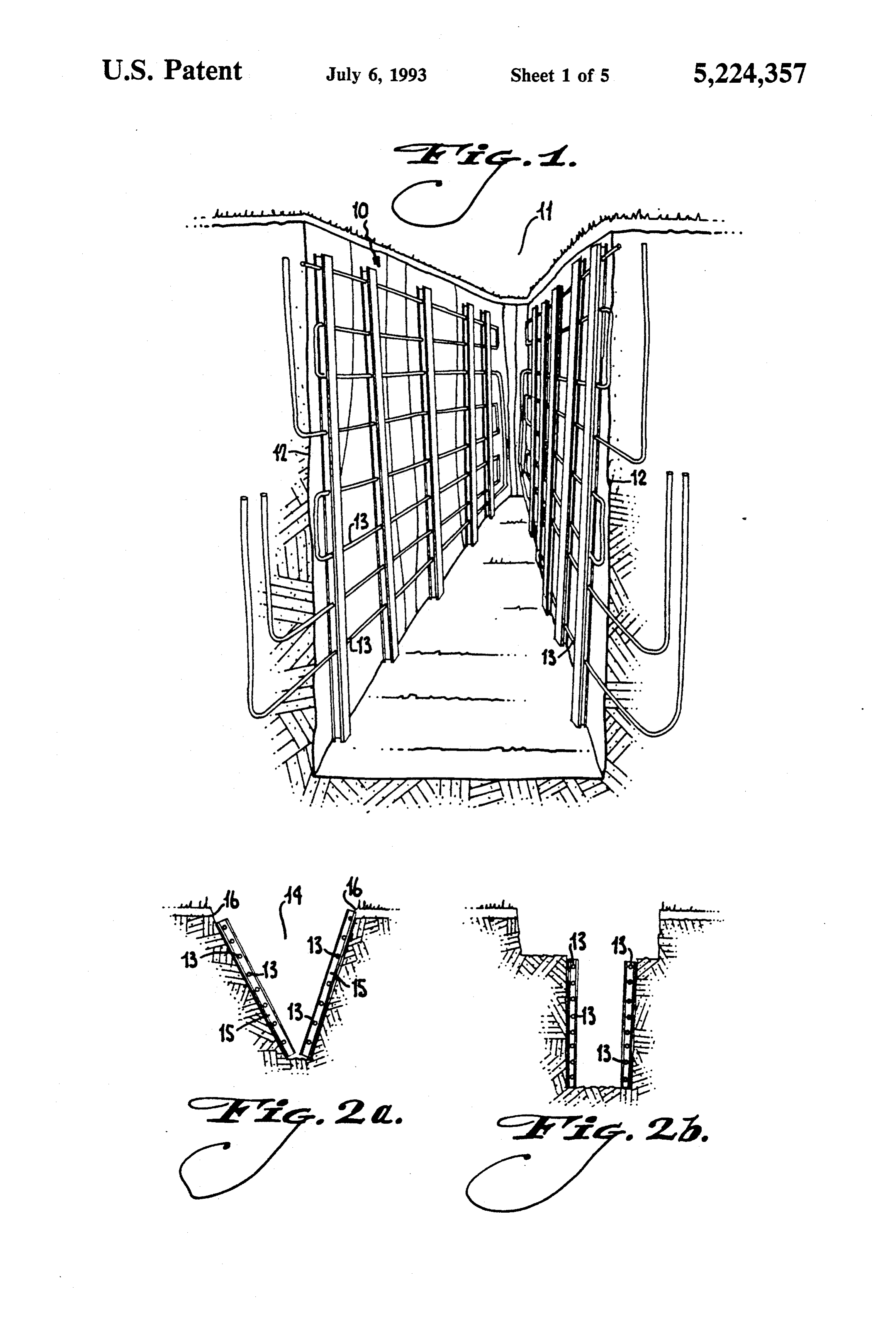
extensive testing, that larger than expected COPs result System operation, such as compressor cycling, con from the use of an oversized coil in the air handler. The pressor shut-down and thermostat monitoring are su measured COP of the invention is in the range of 4's to pervised by a system controlling microprocessor. The 7's, representing a significant improvement over known 45 microprocessor provides an efficient method for match ground source systems. The trenched ground source ing compressor operation to operating conditions. This heat exchanger of the invention provides more energy is a unique control method heretofore unknown in a to the refrigerant, or extracts more energy, than other direct exchange ground source heating/cooling system. ground source techniques, enabling use of the larger air As a further method of matching compressor opera handler heat exchange coil on the indoor heat ex 50 tion to operating conditions, a variable frequency drive changer. modulates the compressor speed. Thus, the compressor Copper coils, or those of other metal, when used with can be operated at a rate consistent with the amount of ground source heat pumps provide superior thermal heating or cooling required by the load. conductivity between the carried refrigerant and the ground. Unfortunately, when buried in the ground, 55 BRIEF DESCRIPTION OF THE DRAWINGS copper and other highly conductive metals are prone to There are shown in the drawings exemplary embodi corrode, via chemical reactions involving a loss of elec ments of the invention as presently preferred. It should trons, especially in acidic soils having a pH below 5.0. be understood, however, that the invention is not lim The corrosive process is known as oxidation and is ited to the precise arrangements shown, and is capable similar to the reaction in a battery, resulting in a net of variations in accordance with the scope of the inven electron flow from the copper metal to the acid in the tion as disclosed and claimed. In the drawings, soil. As the reaction continues over time, the copper FIG. 1 is a perspective view, partly in section, of a becomes excessively oxidized whereby it becomes brit trench heat exchanger according to the invention, tle and susceptible to holes or breakage. awaiting backfilling.
The invention uses cathodic protection to protect the 65 FIGS. 2a and 2b are section views of alternative copper heat transfer coils and to prevent oxidation from trench configurations, the heat exchanger having a providing a thermal barrier between the heat conduc V-shaped design (FIG. 2a), and providing a working tive copper and the surrounding soil. Cathodic protec area above the trench (FIG.2b).
Page 11
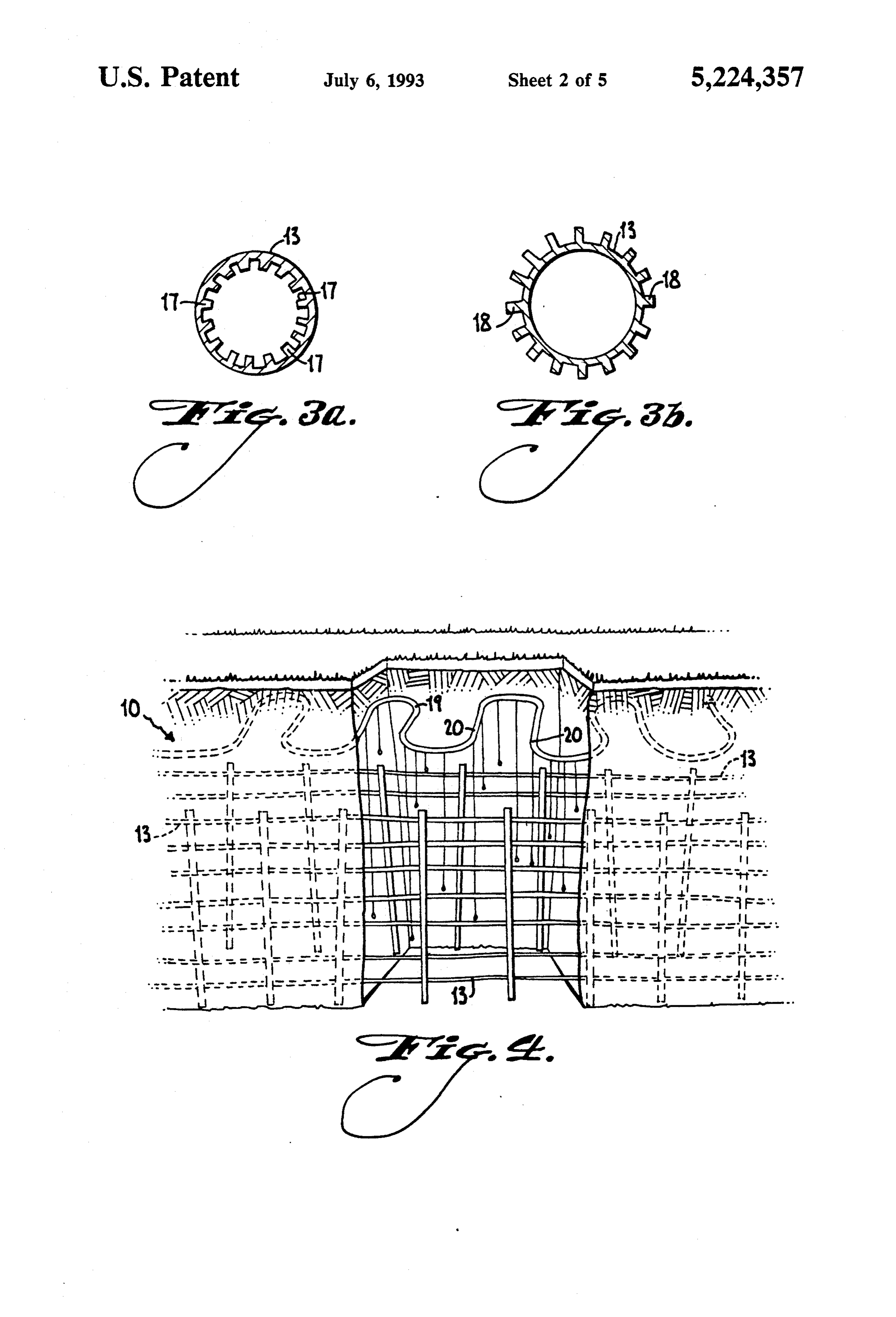
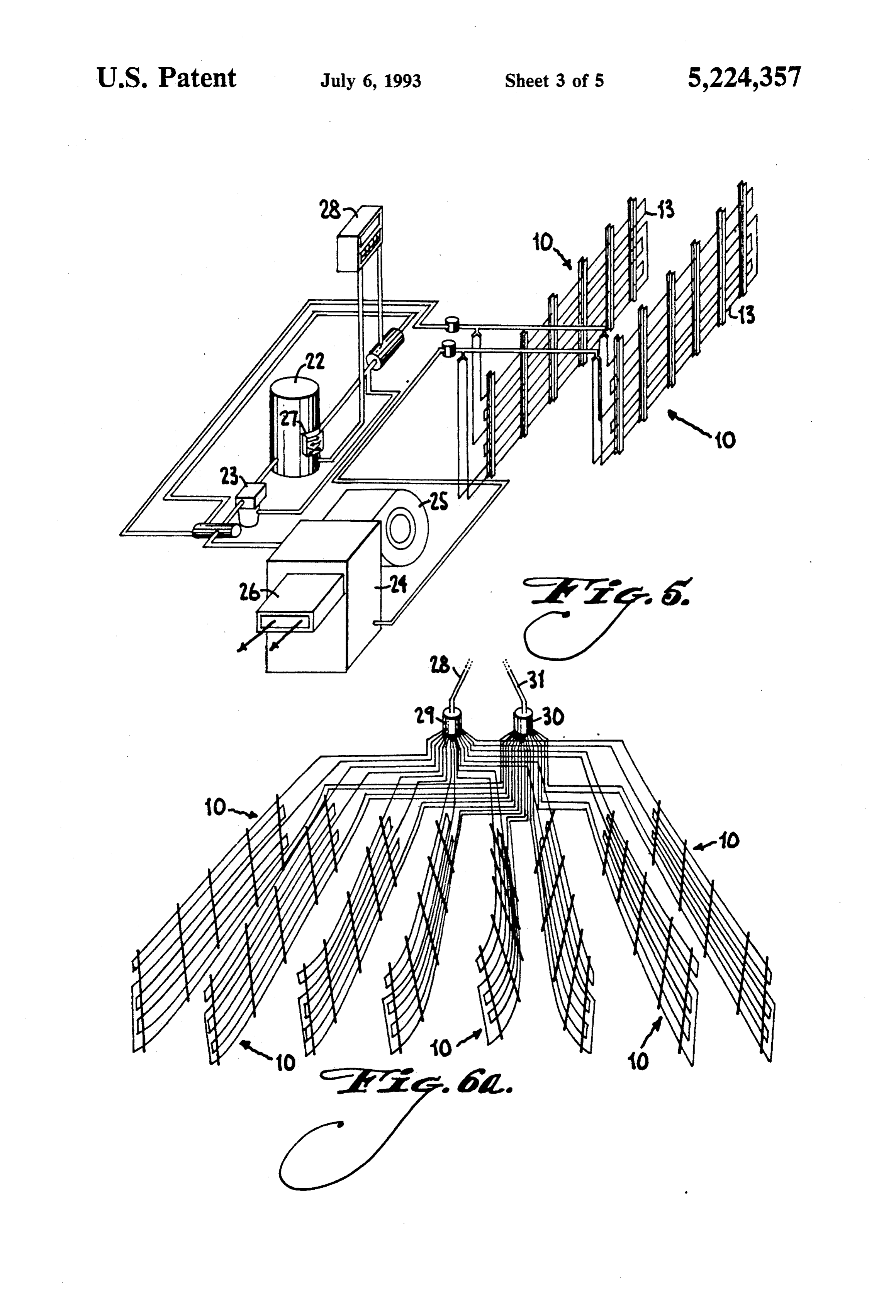
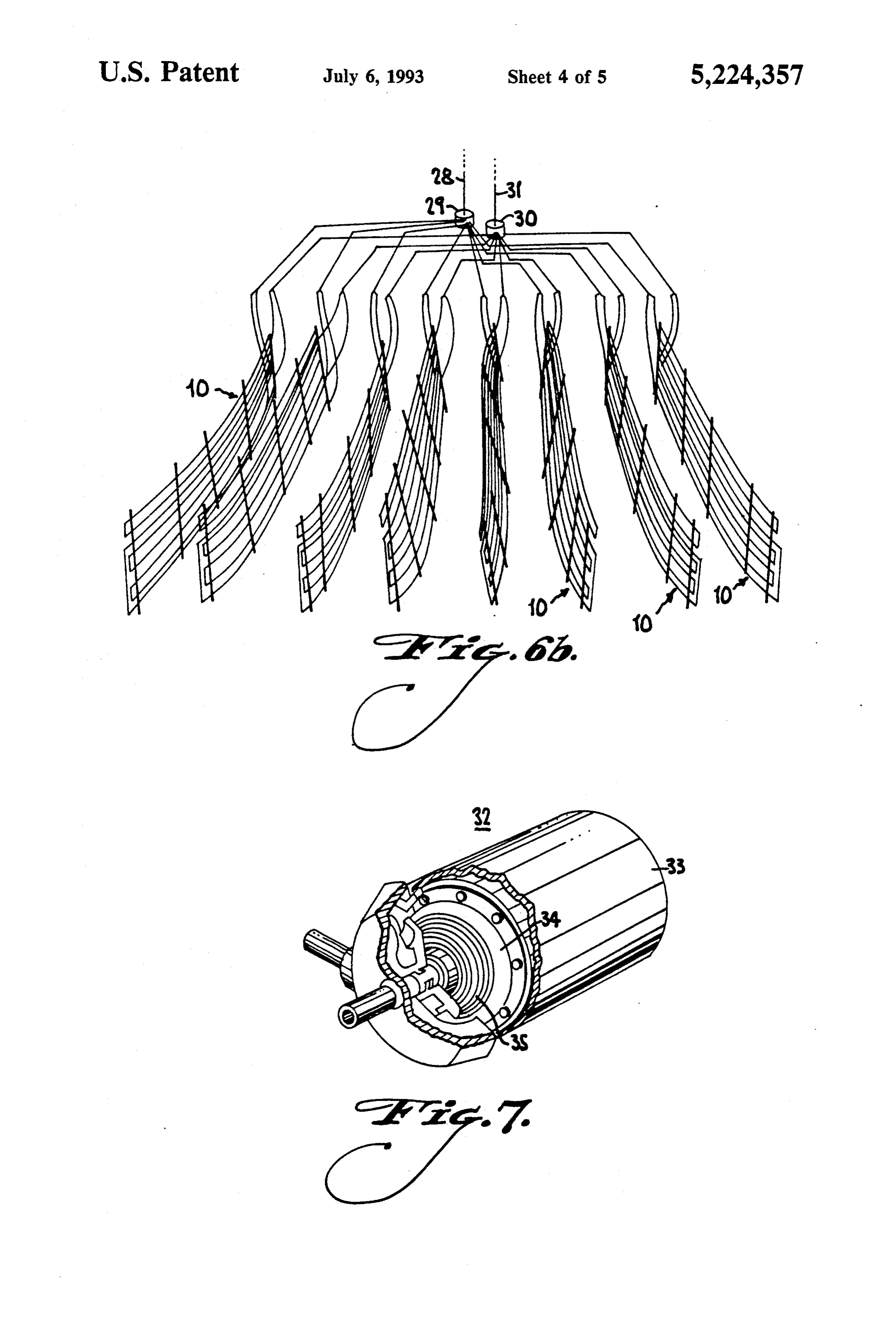
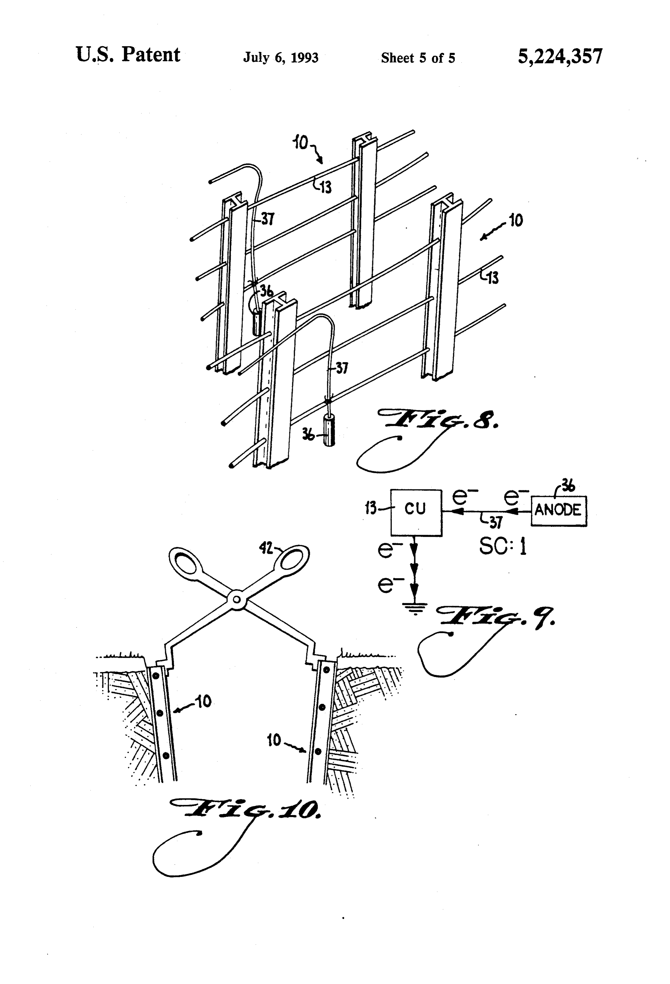
FIGS. 3a and 3b are section views through a conduit after disposition of tube bundles 15 within V-shaped of the heat exchanger wherein the surface area is in trench, 14, trench 14 is filled with soil and compacted to creased by rifling and/or splines or fins. produce thermal communication between tubes 13 and FIG. 4 is a schematic illustration, in perspective, of an the soil. The uppermost tube is normally installed at a alternative embodiment of the heat exchanger after sufficient distance from the surface to avoid problems backfilling, including a fluid delivery means for facili with frost heaving. However, in warmer climates the tating compaction and heat exchange. uppermost tube can be nearer the surface, as shown in FIG. 5 is a schematic perspective diagram illustrating FIG. 2a. Of course, the uppermost tube should be the elements of a full heat pump system according to the spaced at least somewhat below the surface, to avoid invention 10 temperature variations in the ground due to ambient FIGS. 6a and 6b are perspective views illustrating a conditions above the surface. In hot, desert areas, the field of heat exchangers according to the invention, uppermost tube is normally installed at a sufficient with alternative connections to distribution nodes. depth so as to avoid daily adverse effects from the sun. FIG. 7 is a cut away perspective view illustrating the In FIG. 2b, the trench is formed with a rectangular scroll type compressor according to the invention. 15 lower cross section substantially as high as the tube FIG. 8 is a perspective view showing a cathodic bundles, and a wider rectangular cross section from that protection system for use in the system. point to the surface of the ground. This arrangement FIG. 9 is a schematic showing electron transfer asso provides a safe working area on the ledge thereby ciated with the cathodic protection system. formed, allowing installers to manipulate the tube bun FIG. 10 is a schematic illustration showing installa 20 dles without having to reach down from the surface or tion of tube bundles in a trench, using a spreading tool. enter the deep and narrow part of the trench. DETAILED DESCRIPTION OF THE In the embodiments shown, a separate tube bundle is PREFERRED EMBODIMENTS provided for each opposite side of the trench. It is also possible, particularly in a rectangular trench, to provide
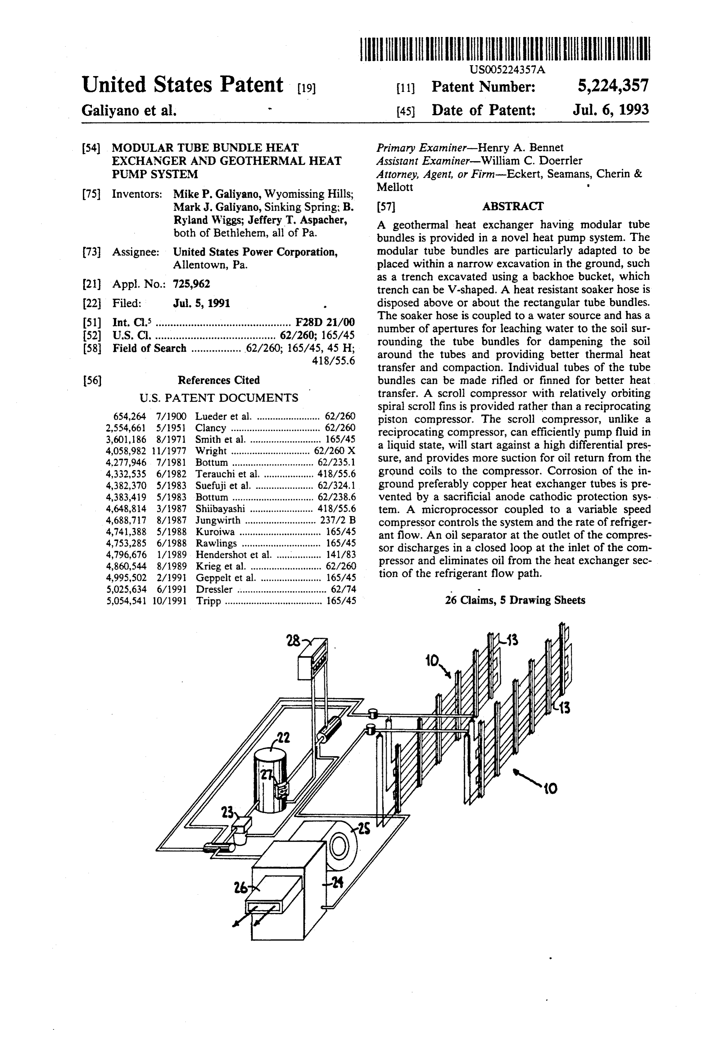
The elements of an improved ground source heat 25 one long bundle for each trench, wrapping the bundle pump system according to the invention are illustrated around the end of the trench such that only one set of generally in FIG. 5, and more particularly in the re connections are needed per trench.
maining drawings. The system has an in-ground heat Tubes 13 carry a fluid refrigerant for thermal ex exchanger and a building heat exchanger coupled via change with the soil. Thermal transfer efficiency will be conduits for refrigerant to at least one compressor and 30 increased if the surface contact area between tubes 13 at least one expander, the compressor having at least and the soil is maximized. For this reason, the tube one intake line and at least one discharge line. The in construction depicted in FIGS. 3a and 3b is provided ground heat exchanger is an improved configuration for use with tube bundles 10 or 15.
including at least one modular tube bundle. The bundle In FIG. 3a, tubes 13 have internal rifling 17 to in comprises a plurality of tubes disposed substantially 35 crease the surface contact area between the coolant horizontally in a stacked vertical array for vertical in fluid and the tube 13 body. Since tube 13 is in tight stallation in trenches, the top of the bundle being in communication with the soil, the rifling, in effect, in stalled below a predetermined line. A distributor having creases the surface area of communication between the a series of orifice plates and fittings is arranged to dis coolant fluid and the soil.
tribute the refrigerant flow evenly to the tubes. In FIG. 3b, tube 13 has external fins or splines 18 for FIG. 1 depicts modular tube bundle 10 disposed increasing the surface area of tube 113 communicating within a U-shaped trench 11 having trench walls 12. with the soil. The greater surface area of tube 13 com Trench 11 is preferably excavated by back-hoebucket municating with the soil, the higher the thermal energy to a desired depth. Typically, the depth is sufficient transfer efficiency between the coolant fluid and the whereby tube bundle 10 is disposed below the frost line. 45 soil.
The excavation of trench 11 with a back-hoebucket and The extent of soil compaction about tube bundle 10 or the placement of bundle 10 within trench 11 is a simple 15 also affects the efficiency of heat transfer. To im process and a great improvement over prior art designs prove compaction, the embodiment of FIG. 4 is pro requiring significant excavation, land area usage and/or vided. In FIG. 4, tube bundle 10 having individual tubes hole drilling effort. After disposing tube bundle 10 in SO 13 is disposed in a trench, shown backfilled. A heat excavation 11, excavation 11 is filled-in with soil and resistant soaker hose 19 is disposed in the soil just above compacted. The individual tubes 13 of tube bundle 10 tube bundle 10 (or 15), or otherwise in close proximity. thereby communicate with the compacted soil for effi The soaker hose is releasably coupleable to a water cient thermal energy exchange therebetween. source and has a plurality of apertures 20 disposed along An alternate arrangement is depicted in FIG. 2a. In 55 the length of its body. Water from the water source FIG. 2a, V-shaped trench 14 is excavated using proper flows into soaker hose 19 and drips out of the plurality machinery. The trench 14 can also be formed by a back of apertures 20. The end 41 of soaker hose 19 opposite hoe, however, the ground may be such that the sides the water source is preferably sealed. Water dripping collapse, or a V-shaped trench may be formed deliber from apertures 20 in soaker hose 19 moistens the earth ately such that the tubes define a larger horizontally compacted about tube bundle 10 whereby the earth inclined section. A V-shaped configuration is formed settles tightly around individual tubes 13 to increase the using tube bundles 15 disposed on opposite sides at the efficiency of heat transfer. Soaker hose 19 is preferably base of V-shaped trench 14. Tubes 13 of V-shaped tube constructed of a heat resistant materialso as to be unaf bundle 15 thereby lie adjacent to the trench walls 16. fected by heat radiated from tube bundle 10 or 15. In the V-shaped trench 14 provides advantages since the out 65 summer, the moisture/humidity removed from the air ward sloping walls 16 are less prone to collapse during via the interior air handler is preferably drained into the excavation or when installing V-shaped tube bundle 15. soaker hose so as to help dissipate heat around coils in As with a U-shaped or rectangular cross section trench, the ground and as to increase system efficiency.
Page 12
FIG. 5 depicts a ground source heat exchange system To increase efficiency of heat transfer, and to provide 21 incorporating tube bundle 10. Compressor 22 is a the necessary heating or cooling to larger loads, a plu common reciprocating type compressor for pumping rality of tube bundles 10 (or 15) can be provided. FIGS. the coolant fluid through system 21. Compressor 22 6a and 6b show alternative connection arrangements for requires lubricating oil for lubricating its moving parts a field of tube bundles or the like. In FIG. 6a, tube to ensure proper operation. Lubricating oil from com bundles 10 are connected in parallel, the respective pressor 22 will mix with the fluid coolant and be liquid connections being coupled to one manifold and pumped through system 21. An excessive loss of lubri the respective vapor connections being coupled to an cating oil, due to oil remaining in the ground coils, will other manifold. In FIG. 6b, the individual tube bundles disable compressor 22. Oil separator 23 is therefore 10 each coupled to a separate inlet and outlet manifold, and provided to extract lubricating oil from refrigerant fluid the respective manifolds are then coupled to manifolds where it is returned to an input of compressor 22. With leading to the conduits coupled to the compressor and out ever having an opportunity to flow into, or remain expander. Input conduit 28, for example, delivers refrig in, the ground coils, oil separator 23 is preferably dis erant fluid to manifold 29 for distribution to each of tube posed at an output of compressor 22 for removing oil 15 bundle 10. After flowing through tube bundle 10 and from the refrigerant downstream of the compressor and exchanging thermal energy with the soil, the refrigerant upstream of the tube bundles. Oil separator 23 removes fluid flows to manifold 30 where it is transferred to and accumulates the oil and outputs removed oil to the return conduit 31. The designation of input conduit 28 input of compressor 22, substantially eliminating oil 20 and return conduit 31 is, of course, completely arbitrary from the flowing refrigerant yet ensuring lubrication of due to the reversibility of system 21. compressor 22 lubrication. The use of an oil separator in As discussed above, prior art reciprocating compres this manner is unique to the ground source heat pump sors are problematic in that they are subject to failure system of the invention, and represents an improvement when not properly lubricated and experience loading problems upon start-up. Furthermore, reciprocating over the prior art, wherein complicated designs are compressors are designed primarily to pump refrigerant employed in an attempt to return oil from the in-ground lines rather than simply keeping the oil out of the in in the gaseous state and can be blocked or slugged when attempting to compress liquid. The scroll compressor of ground section of the lines in the first place.
Exchange coils (not shown) reside within air ex FIG. 7 is therefore provided.
change unit 24. Air handler unit 24 is mounted within 30 taining acompressor
Scroll 32 has cylindrical housing 33, con the confines of the structure to be heated or cooled by spiral fin impeller memberto34orbit motor coupled a movable involute relative to a mating fixed system 21. Air from air blower 25 is blown across the fin scroll 35. A coupling at the axial outside of housing coils within air handler unit 24 and is heated or cooled by the thermal energy of the refrigerant fluid in the coils impeller member and the fixed scroll. With orbitingthe 33 defines the inlet, admitting refrigerant between
of air handler unit 24. The heated or cooled air is ex 35 the movable impeller member 34 relative to the pelled into the structure from vent 26 of air handler unit 35, crescent shaped openings defined between the fins fixed fin 24. It has been found that by increasing the capacity of progress radially inwardly, and become smaller, air handler unit 24 as compared to known ground thereby
Source heat pumps or known air-to-air heat pump sys the axial compressing center. An the refrigerant and moving it to outlet communicating with the area tems, specifically by increasing the size of the coils 40 of the center discharges the relative to the compressor capacity, the coefficient of scroll compressor suitable forcompressed refrigerant. A performance (COP) of system 21 can be increased re available from the Copeland Corporation. invention is use with the markably. It has been discovered that by proper match Scroll compressor 32 is less susceptible to slugging ing of a larger number of coils than customary in an air than a piston compressor, and can efficiently pump handler 24 with a system 21 the COP is increased from 45 liquid or gas as well as liquid/gas mixtures. Further a typical value in the 2's to 5's for prior art designs to more, scroll compressor 32 does not experience loading typical values in the 4's to 7's, or higher. According to problems at turn-on and can start against high or low the invention the increased COP is obtained by increas differential refrigerant pressure.
ing the size of the air handler coils 25% to 45% over Individual tubes 13 of tube bundles 10 or 15 are gen standard industry sized coils compatible with a given 50 erally constructed of copper or aluminum or some simi compressor size. lar highly conductive metal or plastic. It has been found As discussed, system 21 can be used for both heating that copper provides excellent heat transfer between and cooling. Change of the system from heating to refrigerant fluid and the soil. Copper, however, when cooling requires a reversal of flow of fluid refrigerant placed in soil, especially soil having a low pH (acidic) through the system. In order to accomplish such rever 55 and low resistivity, is subject to corrosion in the form of sal, reversing valve 27 is provided. oxidation. The chemical reaction behind the oxidation During operation, system 21 is preferably controlled of a metal, such as copper, involves a loss of electrons by a thermostat for proper heat regulation. The thermo from stat will act throughout the course of a period of opera copperthetubes metal. To prevent a loss of electrons from the 13 of tube bundles 10 and 15 the cathodic tion to switch the compressor off and on, and in con 60 protection system of FIGS. 8 and 9 is provided. In FIG. junction with other controls will reverse the flow of 8, sacrificial anode 36 is electrically coupled directly to refrigerant through the system. Various problems occur a tube 13 of tube bundle 10. The electrical coupling can when a compressor is manipulated as such, including be accomplished by use of wire 37 or other conductive short cycling, low refrigerant pressure, and high refrig component. Sacrificial anode 36 is a metal dissimilar to erant pressure, which could possibly damage compres 65 copper and optimum results occur when sacrificial sor 22. It is desirable therefore to provide system 21 anode 36 is magnesium or zinc.
with a microprocessor control unit 28 for controlling The reaction occurring between copper tubes 13, system operation. anode 36 and acidic soil is shown in FIG. 9. Sacrificial
Page 13
anode 36 releases electrons which travel to copper tub another, and the refrigerant being subjected to ing 13 through wire 37. Copper tubing 13 emits elec phase change in the conduits. trons to the soil which acts as an electron sink. The 2. The ground source heat pump system according to copper, although losing electrons to the soil, is continu claim 1 wherein the trenches are dimensioned for exca ously supplied with electrons from sacrificial anode 36. vation with a backhoe.
The copper tubing 13 therefore does not experience a 3. The ground source heat pump system according to net loss of electrons and hence does not oxidize. The claim 1 wherein said top of said at least one tube bundle sacrificial anode 36 does experience a net loss of elec is installed below a frost line. trons and will oxidize over time, but can easily be re 4. The ground source heat pump system according to placed. Sacrificial anode 36 is sacrificed to save copper O claim 1 wherein said tubes have at least one of rifled tubing 13. inner-walls and finned outer walls to increase heat ex It can be appreciated from the above that the inven change efficiency.
tion provides a much improved ground source heat 5. The ground source heat pump system according to pump system by eliminating draw backs of prior art claim 1 further comprising a reversing valve operable to systems including excessive land usage and complex 15 equalize refrigerant pressure when the system is shut difficult excavation required for installation of heat off.
exchange tubing. Furthermore, the inclusion of a scroll 6. The ground source heat pump system according to compressor eliminates maintenance and reliability prob claim 1 further comprising a variable frequency drive lems associated with ground source heat exchange sys operable to modulate compressor speed to match hea tems using reciprocating type compressors. Micro 20 ting/cooling capacity to load conditions. processor control of the system is provided for further 7. The ground source heat pump system according to improving efficiency and reliability. Cathodic protec claim 1 further comprising a heat-resistant soaker hose, tion is included to prevent corrosive oxidation of the said hose having intermittently spaced apertures and an in-ground coils. Soaker hoses are provided to enhance above ground attachment end for decoupleable attach prompt soil compaction and improve heat dissipation. 25 ment to a water line, said hose placeable in substantial Installation of the ground heat exchanger of the in proximity to the at least one in-ground tube bundle for vention is relatively simple and safe. Inasmuch as the leaching water to the ground thereby improving earth ground heat exchanger is mounted in a simple backhoe compaction and heat dissipation in-ground about the trench, the area used is modest. The tubes in the bundles tubes.
are affixed to vertical support members, such that the 30 8. The ground source heat pump system according to tubes are readily placed along the sidewalls of the claim 1 comprising a plurality of modular tube bundles trench. As shown in FIG. 10, it is possible to employ a and further comprising at least one distributor having a lever device 42 to bear outwardly on the vertical sup series of orifice plates and fittings arranged to evenly ports such that the tube rest immediately against the distribute the refrigerant flow to said tubes. trench walls when backfilling. By mounting and install 35 9. An improved ground source heat pump system, ing the tubes in this manner, there is no need to make comprising:
connections or install further fixing mechanisms in a an in-ground heat exchanger and a building heat ex manner that might require the worker to enter the changer coupled via conduits for refrigerant to at trench. least one compressor and at least one expander, the While specific embodiments of the invention have compressor having at least one intake line and at been described in detail, it will be appreciated by those least one discharge line, the compressor and the skilled in the art that various modifications and alterna expander being coupled to the conduits such that tives to those details could be developed in light of the the refrigerant is circulated in the conduits through overall teachings of the disclosure. Accordingly, the pressure changes and corresponding temperature particular arrangements disclosed are meant to be illus 45 changes in the refrigerant, the in-ground heat ex trative only and not limiting as to the scope of the in changer comprising at least one modular tube bun vention which is to be given the full breadth of the dle comprising a plurality of substantially horizon appended claims and any and all equivalents thereof. tally oriented subterranean tubes, buried in a We claim: stacked vertical array for vertical installation in 1. An improved ground source heat pump system, 50 trenches, said at least one bundle having a top and comprising: bottom displaced vertically from one another, and an in-ground heat exchanger and a building heat ex the refrigerant being subjected to phase change in changer coupled via conduits for refrigerant to at the conduits; and, least one compressor and at least one expander, the wherein said compressor comprises a scroll compres compressor having at least one intake line and at 55 sor having a spiral impeller orbiting relative to a least one discharge line, the compressor and the fixed spiral scroll, whereby orbiting of said impel expander being coupled to the conduits such that ler pumps refrigerant through the system in a man the refrigerant is circulated in the conduits through ner insensitive to phase of the refrigerant. pressure changes and corresponding temperature 10. The ground source heat pump system according changes in the refrigerant, the in-ground heat ex to claim 1 wherein the tubes are constructed of copper, changer comprising at least one modular tube bun further comprising a dissimilar metal electrically cou dle comprising a plurality of substantially horizon pled to at least one of the copper tubes, said dissimilar tally oriented subterranean tubes, buried in a sub metal acting as a sacrificial anode providing a flow of stantially planar vertical array for installation along electrons to said tubes, thereby preventing oxidation of substantially vertical walls of at least one that is 65 said copper tubes.
backfilled for setting the array in thermal engage 11. The ground source heat pump system according ment with the earth, said at least one bundle having to claim 10 wherein said dissimilar metal is one of mag a top and bottom displaced vertically from one nesium and zinc.
Page 14
12. The ground source heat pump system according the sacrificial anode providing cathodic protection to claim 1 wherein said at least one bundle forms a against corrosion of the tubes. V-shaped configuration having a top and a bottom, 19. The ground source heat pump system according comprising a plurality of horizontally parallel tubes to claim 14, further comprising an oil separator coupled vertically spaced at increasing horizontal distances 5 in series with the discharge line of the compressor, the apart from bottom to top for disposition in a V-shaped oil separator extracting oil from the discharge line up trench. stream of the conduits, the oil separator having an outlet 13. The ground source heat pump system according coupled to the intake line of the compressor, whereby to claim 1 wherein the building heat exchanger is cou the compressor is lubricated while minimizing oil in the pled to a load including at least one of a building HVAC 10 in-ground heat exchanger.
air handler and a hot water heat exchanger. 20. The improved ground source heat pump system 14. An improved ground source heat pump system of according to claim 14, wherein the trench is substan the type having an in-ground heat exchanger and a tially V-shaped, whereby the substantially planar array building heat exchanger coupled via conduits for refrig diverges outwardly along walls of the trench. erant to at least one compressor and at least one expan- 15 21. The improved ground source heat pump system der, the at least one compressor having at least one according to claim 14 wherein the trench is dimen intake line and at least one discharge line, the improve sioned for formation via a backhoe. ment comprising: 22. The improved ground source heat pump system said in-ground heat exchanger having a plurality of according to claim 14, wherein the compressor con tubes disposed in a substantially planar array which 20 prises a scroll compressor having a spiral impeller orbit is inclined along a wall of a trench, said trench ing relative to a fixed spiral scroll, whereby orbiting of being backfilled for setting the planar array in ther said impeller pumps refrigerant throughout the system. mal engagement with the earth. 23. The improved ground source heat pump system 15. The ground source heat pump system according according to claim 14, further comprising a reversing to claim 14 wherein said tubes have at least one of rifled 25 valve for equalizing refrigerant pressure when the sys inner walls and finned outer walls to increase heat ex tem is shut off.
change efficiency. 24. The improved ground source heat pump system 16. The ground source heat pump system according according to claim 14, further comprising a distributor to claim 14 further comprising a variable frequency couple to the tubes bundles, having a series of orifice drive to modulate compressor speed to match heating 30 plates and fittings arranged to evenly distribute refriger /cooling capacity to load conditions. ant flow to said bundles. 17. The ground source heat pump system according 25. The improved ground source heat pump system to claim 14 further comprising a heat-resistant soaker according to claim 1, further comprising an oil separa hose, said hose having intermittently spaced apertures tor attached at a discharge line of a compressor to sepa and an above ground attachment end for decoupleable 35 rate the oil from the gaseous refrigerant, the oil separa attachment to a water line, said hose placeable in sub tor having an outlet coupled to an inlet of the compres stantial proximity to the in-ground heat exchanger for sor whereby oil in the conduits in minimized. leaching water to the ground thereby improving earth 26. The improved ground source heat pump system compaction about the exchanger. according to claim 1, wherein the compressor com 18. The ground source heat pump system according 40 prises a scroll compressor having a spiral impeller orbit to claim 14 wherein the in ground heat exchanger in ing relative to a fixed spiral scroll, whereby orbiting of cludes a plurality of metal tubes buried in soil, and fur said impeller pumpss refrigerant through the system. ther comprising a sacrificial anode coupled to the tubes,
Provenance
- Collection
- Cited prior art
- Original PDF
- patentimages.storage.googleapis.com →
- Filed
- 1991-07-05
- Pages
- 14
- Method
- pdftotext (the PDF's own text layer) + pdftoppm 300dpi page scans
- Source
- Google Patents bibliographic record
- Granted
- 1993-07-06
- Inventors
- Mike P. Galiyano; Mark J. Galiyano; B. Ryland Wiggs; Jeffrey T. Aspacher; U S Power Corp
- Transcribed from
- patentimages.storage.googleapis.com →