patent · US5762779
Method for producing electrolyzed water
9 June 1998
Page 1 — bibliographic record
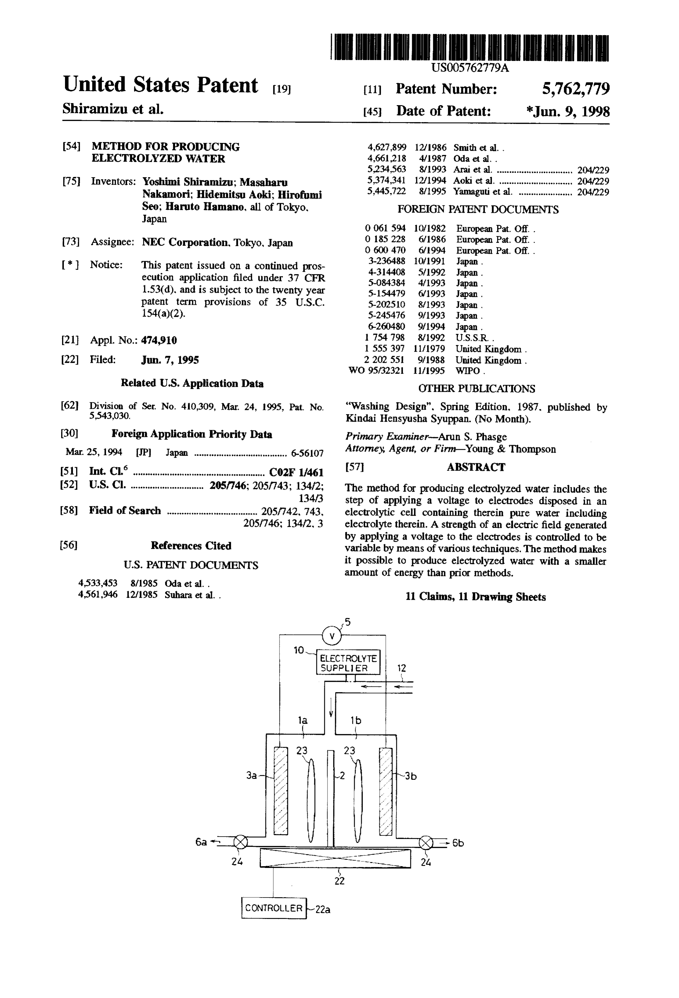
United States Patent (19) 11) Patent Number: 5,762,779 Shiramizu et al. 45 Date of Patent: *Jun. 9, 1998 (54) METHOD FOR PRODUCING 4,627,899 12/1936 Smith et al. . ELECTROLYZED WATER 4,661.218 4/1987 Oda et a .
5,234,563 8/1993 Arai et al. ............................... 204/229 (75) Inventors: Yoshimi Shiramizu; Masaharu 5,374,34 12/1994 Aoki et al. .......... ... 204/229 Nakamori; Hidemitsu Aoki; Hirofumi 5,445.722 8/1995 Yamaguti et al. ...................... 204/229 Seo; Haruto Hamano, all of Tokyo, FOREIGN PATENT DOCUMENTS
Japan
73 Assignee: NEC Corporation, Tokyo, Japan O 185228 6/1986 European Pat. Off. .
* 3.236488 10/1991 Japan. Notice: This patent issued on a continued pros 4-314408 5/1992 Japan.
ecution application filed under 37 CFR 5-0843.84 4/1993 Japan.
1.53(d), and is subject to the twenty year 5-154479 6/1993 Japan.
patent term provisions of 35 U.S.C. 5-20251O 8/1993 Japan.
154(a)(2). 5-24.5476 9/1993 Japan .
21 Appl. No.: 474,910 754 798 8/1992 U.S.S.R.
22 Fied: Jun. 7, 1995 2 202 551 9/1988 United Kingdom.
Related U.S. Application Data OTHER PUBLICATIONS 62 Division of Ser. No. 410,309, Mar. 24, 1995, Pat No. “Washing Design". Spring Edition, 1987. published by 5.543,030. Kindai Hensyusha Syuppan. (No Month). (30) Foreign Application Priority Data Primary Examiner-Arun S. Phasge Mar. 25, 1994 Pl Japan ..................................... 6-56107 Attorney, Agent, or Firm-Young & Thompson (51) Int. Clair. CO2F 1/461 57 ABSTRACT 52 U.S. Cl. ............................. 205/746; 205/743; 134/2; The method for producing electrolyzed water includes the 134/3 step of applying a voltage to electrodes disposed in an 58) Field of Search .................................... 205/742, 743, electrolytic cell containing therein pure water including 205/746; 134/2, 3 electrolyte therein. A strength of an electric field generated by applying a voltage to the electrodes is controlled to be 56) References Cited variable by means of various techniques. The method makes
amount of energy than prior methods.
4,561,946 12/1985 Suhara et al. . 11 Claims, 11 Drawing Sheets
ELECTROLYTE
SUPPLIER
Page 2
Drawing sheet — no readable text.
Page 3
Drawing sheet — no readable text.
Page 4
Drawing sheet — no readable text.
Page 5
Drawing sheet — no readable text.
Page 6
Drawing sheet — no readable text.
Page 7
Drawing sheet — no readable text.
Page 8
Drawing sheet — no readable text.
Page 9
Drawing sheet — no readable text.
Page 10
Drawing sheet — no readable text.
Page 11
Drawing sheet — no readable text.
Page 12
Drawing sheet — no readable text.
Page 13
METHOD FOR PRODUCING suitably decomposed and/or neutralized in order to prevent ELECTROLYZED WATER environmental pollution
However, even if it is intended to reduce the amount of
This application is a division of application Ser. No. chemicals to be used by recycling, there is a limitation. In 08/410,309, filed Mar. 24, 1995, now U.S. Pat No. 5.543, 5 view of this problem, the inventors have invented an epochal O30. method for wet treatment which is capable of remarkably reducing an amount of chemicals to be used, and have
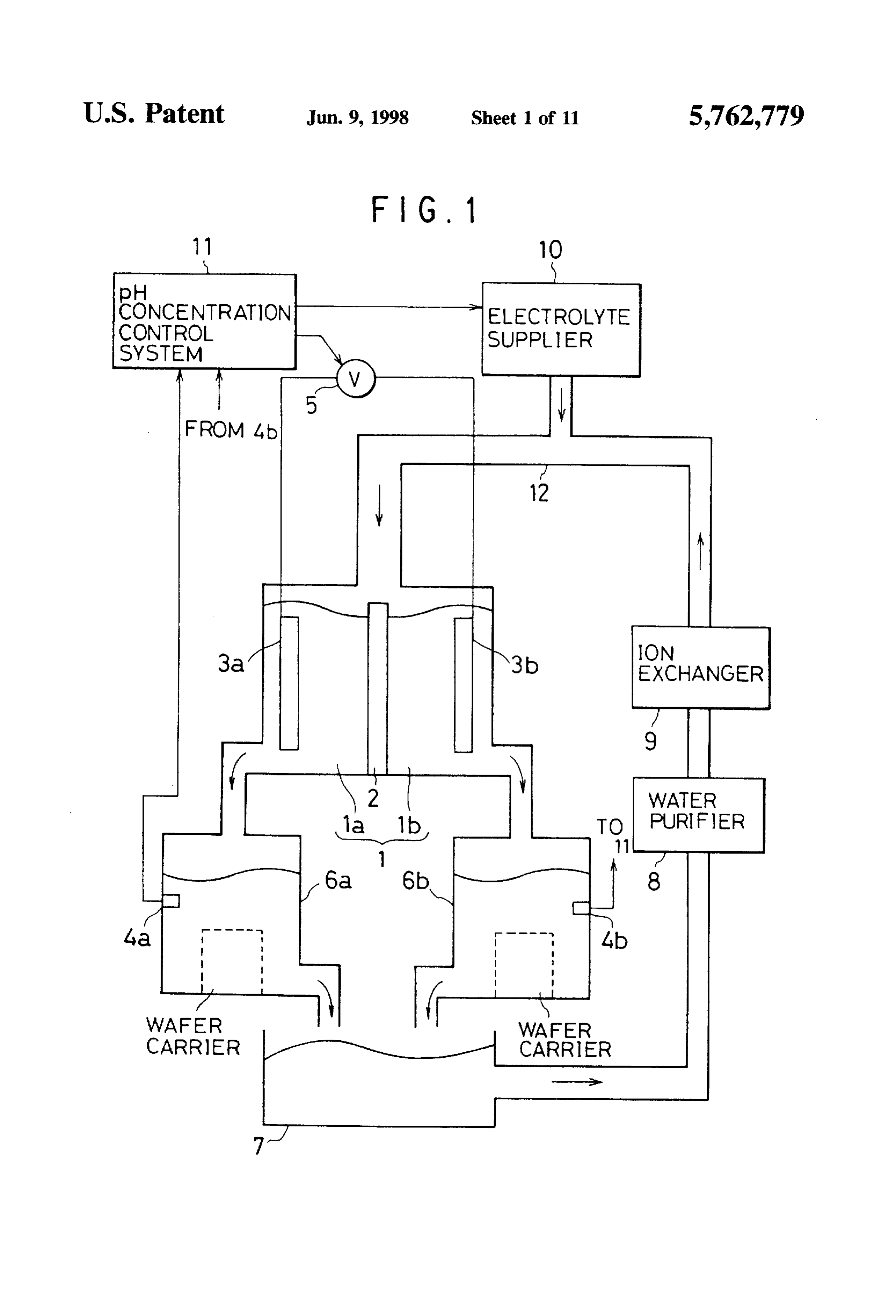
BACKGROUND OF THE INVENTION already filed a patent application with the Japanese Patent 1. Field of the Invention Office as Patent Application No. 5-105991 which was laid 10 open to public on Sep. 16, 1994 as Patent Public Disclosure
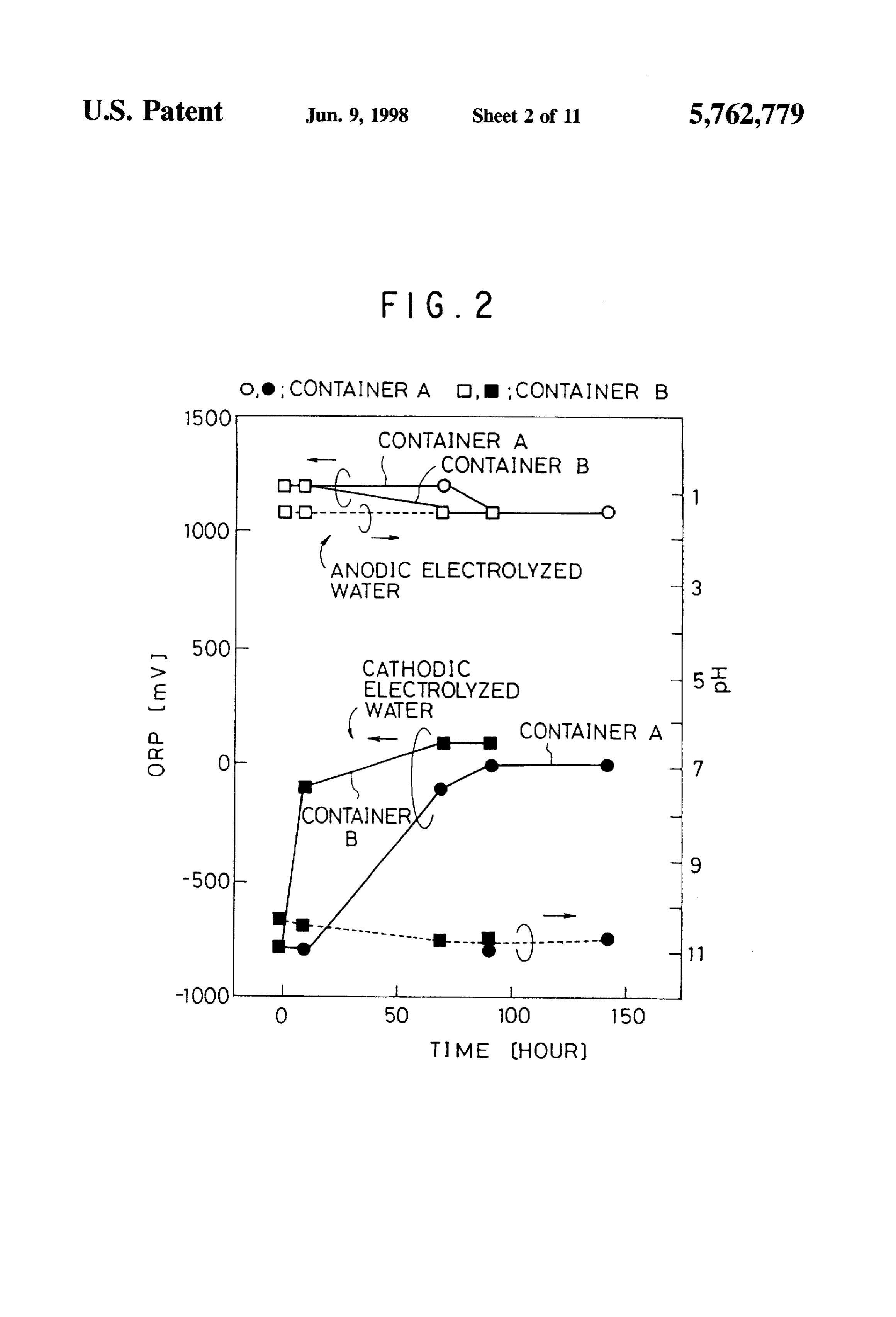
The invention relates to a method for producing electro No. 6-260480. In this patent application, there is disclosed lyzed water, and more particularly to a method for producing a method including the steps of electrolyzing pure water to electrolyzed water to be used for wet treatment of a semi which a quite small amount of electrolyte has been added, conductor such as wet etching. and washing a semiconductor with the thus obtained elec 2. Description of the Related Art 15 trolyzed water. Hereinbelow, there will be explained an A process of manufacturing a semiconductor device apparatus for carrying out the method disclosed in the above requires many wet treatments such as washing, etching and mentioned patent application, but it should be noted that the rinsing. In a process of manufacturing a semiconductor following explanation is only for better understanding of the wafer, after a silicon ingot has grown, wet treatment is present invention, and that the applicants do not admit the indispensable in a wafer slicing step and a mirror polishing 20 above mentioned patent application as prior art. step of a wafer in order to remove various contaminants such Hereinbelow, there will be briefly explained an apparatus as silicon fine particles, abrasive powders and organic sub for wet treatment with reference to FIG. 1. To an electrolytic stances included in abrasive material. In such wet treatments cell 1, there is connected a conduit 12 through which the are used chemicals such as organic solvents, strong acid and electrolytic cell 1 is supplied with pure water recycled strong alkali. In a process of manufacturing a semiconductor 25 through a water purifier 8 and an ion-exchanger 9 from device, prior to wafer processing steps, it is necessary to use waste liquid reservoir 7, and also with electrolyte to be many chemicals such as organic solvents, strong acid and added to the pure water through an electrolyte supplier 10. strong alkali in many steps such as a Blanson washing step The electrolyte is added to the pure water for decreasing the for cleaning a wafer with chemicals, and a photo-lithography specific resistance of the pure water. For instance, bubbling step which further includes resist forming and removing 30 of carbon dioxide (CO) and supporting electrolytic salt of steps, semiconductor layer forming and removing steps. ammonium acetate (CHCOONH) are used as an electro insulating layer forming and removing step and metal layer lyte source. The electrolytic cell 1 is divided into two forming and removing step. sub-cells 1a and 1b by a partition membrane 2 composed of As mentioned above, there are various wet treatments. a material which does not allow water to pass therethrough, The wet treatments used in a process for manufacturing a 35 but allows ion to pass therethrough, such as porous silicon. semiconductor device are grouped into three steps: a wash In each of the sub-cells 1a and 1b is disposed an anode 3a ing step, an etching step and a rinsing step. These three steps and a cathode 3b each composed of platinum (Pt) or carbon can be further categorized to the following three steps (A). (C). The anode 3a is connected to a positive terminal of a (B) and (C). DC voltage source 5, while the cathode 3b is connected to (A) a substrate washing or rinsing step for removing water a negative terminal of the DC voltage source 5. Electrolyzed contaminants adhered to the substrate without giving disposalin cells each of the sub-cells 1a and 1b is introduced into 6a and 6b, respectively. Waste solution dis the substrate any influence. Herein, a substrate charged from the disposal cells 6a and 6b is gathered in the includes, for instance, a semiconductor layer, an insu waste liquid reservoir lating layer and a metal wire. and contaminants include, 45 purifier 8, and further 7.is and then is purified in the water recycled into pure water in the for instance, metal contaminants, organic or inorganic ion-exchanger 9. Each of the disposal cells 6a and 6b is particles, residue of resist and ionic residue. provided with pH sensors 4a and 4b. respectively, for (B) a step for etching a substrate sensing H concentration or OH- concentration of the (C) an etching step for removing natural oxide film or electrolyzed pure water. A pH regulator 11 receives signals organic film formed on a surface of a substrate representing H or OH- concentration from the pH sensors For instance, in step (A) there are often used ammonium 4a and 4b, to thereby provide the electrolyte supplier 10 and peroxide medium (APM) including NHOH, HO and HO the DC voltage source 5 with signals for controlling the DC at a ratio of 1:4:20 and sulfuric peroxide medium (SPM) voltage and the amount of electrolyte to be added to the pure including HSO and HO at a ratio of 5:1. In step (B) there water. Thus, the pH of the electrolyzed pure water is is used hydrochloric peroxide medium (HPM) including 55 maintained in a desired range.
HCl, H2O, and HO at a ratio of 1:1:6 as well as APM and Hereinbelow, there will be explained the method for wet SPM. In step (C) there is used dilute hydrogen fluoride treatment to be carried out using the above mentioned wet (DHF) including HF and HO at a ratio of 1:50 through 400 treatment apparatus. After pure water containing electrolyte as well as APM and SPM. has been provided to the electrolytic cell 1, across the anode Because of much use of chemical agents as 3a and the cathode 3b is applied a DC voltage intensive aforementioned, it is required to have a plant for disposing enough to generate an electric field having the electric field of solid and liquid waste where the plant is expensive to run. strength in the range of 10 to 10' V/cm, whereby the pure Basic material in wet treatments is pure water. The used pure water is electrolyzed. The added electrolyte is being ionized water is recycled by means of a closed system for reuse. to anion and cation in the pure water. Thus, when a DC Similarly, the chemical agents are also recycled for reuse. 65 voltage is applied to the anode 3a and the cathode 3b, the When the life of such recycled chemicals has expired and the ionized anion and cation are attracted to the cathode 3b and chemicals are to be discarded, the chemicals are to be the anode 3a, respectively, whereby an electrical current is
Page 14
generated across the electrodes 3a and 3b. The generation of enlarged, a greater amount of electrolyzed water can be an electrical current triggers electrolysis of the pure water. produced, but the consumption of electrical power is also On the surface of the anode 3a is generated oxygen gas (O), increased. Thus, the above mentioned method cannot further and thereby anodic water is generated. Herein, anodic water increase the production efficiency of electrolyzed water. means water containing a high concentration of H ion Furthermore, the production of electrolyzed water (anodic therein. On a surface of the cathode 3b is generated hydro water or cathodic water) has been controlled by monitoring gen gas (H2), and thereby cathodic water is generated. a pH value. that is. H' concentration or a pCH value. that is. Herein, cathodic water means water containing a high con OH- concentration. However, the inventors have discovered centration of OH- ion therein. The anodic water is acidic, the fact that ORP which means a potential representing, the and is effective in the removal of contaminants contaminated O intensity of oxidation or reduction, may vary though a pH with heavy metal, which used to be performed by using SPM value hardly varies at all in the case of electrolyzed water. and HPM. and also in metal etching The cathodic water is In addition, the inventors have also discovered the fact that alkaline, and is effective in the removal of abrasive colloidal ORP is a parameter which is capable of varying indepen silica and residual chlorine ion, which used to be performed dently of a pH value.
by using APM. The used anodic and cathodic water are 15 FIG. 2 is a graph showing successive change of a pH mixed with each other in the waste liquid reservoir 7, and are value and ORP overtime when anodic and cathodic waters regenerated to pure water. are stored for 0 through 140 hours in two polyethylene In accordance with the method mentioned so far, it is containers A and B of openings having different diameters. possible to remarkably reduce the use of chemicals such as The container A has a barrel body having about 10 cm of acid and alkali with the result of smaller amount of waste. diameter and has a narrow opening having 1.5 cm of Thus, compared to a conventional method, the method diameter, while the container B has a barrel body having makes it possible to reduce the amount of waste and cost for about 10 cm of diameter and has an opening having the same disposing of waste, and also makes it unnecessary to build diameter as that of the body. Each of the containers A and B a waste disposing plant, with the result of lower manufac is filled with electrolyzed water, and is hermetically sealed turing cost of semiconductors. Thus, large economic advan 25 with a cap. As a result of this experiment, the inventors tages can be expected. discovered that ORP remarkably varies though the pH value In "Washing Design". Spring Edition. 1987, published by only slightly varies. The cathodic water varies more remark Kindai Hensyusha Syuppan, an article titled "Redox wash ably than the anodic water, and ORP varies in a different way ing method: New washing method in electronic industry" in each of the containers A and B. For instance, when the has suggested a method in which electrolyzed water is used, cathodic water having a pH of 10.5 and an ORP of -800 mV for instance, for silicon etching and for removing oxide film was contained in the container B. the pH value was kept formed on a surface of aluminum layer. The suggested almost constant for approximately 140 hours, but ORP method includes the steps of electrolyzing pure water or tap returned to approximately 0 mV after only an hour. On the water including a low concentration of electrolyte, and other hand, when the cathodic water was contained in the etching silicon by using the obtained cathodic water. In 35 container A, it took approximately 70 hours for ORP to accordance with the method, impurities adhered to or dis return to approximately 0 mV. The pH value stayed constant, persed on the surface of silicon together with the surface of Though the reason why ORP varies in different fashion in silicon can be removed by etching. If aluminum wiring is dependence on the containers is not known, it is considered immersed in place of silicon, the oxide film formed on the as follows. Though the containers are hermetically sealed surface of the aluminum wiring can be removed without with a cap for isolating the contents from the atmosphere, overetching the aluminum wiring. the cap is removed from the container when ORP is mea When the above mentioned apparatus is to be used in an sured. Thus, the contact area of the electrolyzed water the experiment, only a small amount of electrolyzed water is with atmosphere when a probe is inserted into the electro needed per unit period of time. However, when the apparatus lyzed water is varied in each of the containers. The differ is to be used in actual semiconductor manufacturing step, it 45 ence in contact area between the containers having different is necessary to further increase the ability to produce elec opening diameters may influence ORP. The anodic water trolyzed water. Recently, 8 inch wafers have often been varied more slightly than the cathodic water, but, as is shown used. For instance, if it is intended to cleanse 1 lot including in FIG. 2, ORP decreased from approximately 1200 mV to fifty 8 inch wafers by a batch method, then it is necessary to approximately 1100 mV in 70 hours. The pH value stayed at prepare at least 50 liters of electrolyzed water. However, if 50 approximately 1.5. and did not change. Thus, it was under it takes too long to produce a required amount of electro stood that only ORP was varied in the anodic water. lyzed water, a throughput goes down, and further there is a In view of the above mentioned results, when electrolyzed fear that oxidation reduction potential (hereinafter, referred water is to be used for wet treatment, electrolyzed water has to simply as "ORP") of the electrolyzed water may be to be prepared taking successive changes of ORP into changed. For increasing the production of electrolyzed water 55 consideration. For instance, even though much time is spent only, the electrolysis area may be increased or a larger preparing an adequate amount of cathodic water for elec voltage may be applied to the electrodes. However, if a trolysis in order to remove colloidal silica located on the larger voltage is to be applied to electrodes, it would be silicon, if a lot to be treated arrives too late for some reason, necessary to install a high voltage generating apparatus and the prepared electrolyzed water would be deteriorated and an apparatus for safety, and also be necessary to often hence could not be used. In such a case, the electrolyte and exchange the electrodes because the life of the electrodes is electrical power consumed to produce the electrolyzed water made shorter due to a larger voltage applied thereto. thereby have been wasted. Though electrolyzed water having ORP increasing the cost for such apparatuses. In addition, the having a large absolute value may be produced taking the battery exchanges tend disadvantageously to introduce par deterioration of electrolyzed water into consideration, the ticles and other contaminants, which are the most deadly foe 65 consumption of electrical power is disadvantageously to the wet treatment apparatus, into the wet treatment increased. Thus, it is desired to enhance the production apparatus. On the other hand, if the electrolysis area is to be efficiency of electrolyzed water so that an adequate amount
Page 15
of electrolyzed water can be produced in a short period of starting electrolysis. This ensures that the resistance between time in order to timely prepare electrolyzed water. anode and cathode is smallest, and hence it is possible to The above mentioned article included in "Washing start electrolysis even when the applied voltage is small. Design", Spring Edition, 1987, merely reports that a surface Then, after electrolysis has started, a distance between the of silicon can be etched or an oxide film of aluminum can be electrodes is made larger to thereby decrease the strength of removed by immersing a silicon piece or aluminum wiring. the electric field. The decrease of electric field strength in cathodic water. In addition, when pure water is to be prevents H" ion and OH- ion generated at the anode and electrolyzed, electrolysis cannot be carried out unless a high cathode, respectively, from being attracted to the cathode voltage is applied to the electrodes because pure water has and anode anode, respectively, to thereby prevent neutral a high resistivity, specifically, 18 MQ-cm. Furthermore, it is 1 ization of H' and OH- ions. Thus, H ions remain in the necessary to use a special equipment for applying a high vicinity of an anode to thereby increase H concentration voltage. If pure water contains electrolyte even in a small around the anode, while OH- ions remain in the vicinity of amount, it is possible to decrease the voltage to be applied. a cathode to thereby increase OH- concentration around the However, documents known in the art merely teach elec cathode. Similarly, oxidizing material and reducing material trolyte such as tap water, ethylenediaminetetraacetic acid 15 remain in the vicinity of an anode or cathode. respectively, (EDTA) which is effective in removal of fingerprints, and to thereby increase the concentration thereof around the citric acid. These electrolytes are all unpreferable or the electrodes. Herein, the oxidizing material and reducing most deadly foe to a semiconductor device, and hence material means material which is generated depending on cannot be used. In the above mentioned patent application added electrolyte and electrolysis conditions, and deter filed by the inventors, only an electrolyte having no influ 20 mines ORP. Thus, it is possible to reduce the maximum ence on a semiconductor device is selected for use, but the voltage to be applied to the electrodes, by designing the production efficiency of electrolyzed water is still dissatis distance between the electrodes to be variable. In addition, factory. If the voltage is not increased and the amount of the method makes it easy to increase or decrease the added electrolyte is increased, the production efficiency of production of H" ion, OH- ion, oxidizing material and electrolyzed water can be enhanced. However, in such a 25 reducing material, with the result that it is possible to case, it is impossible to reduce the amount of chemicals to efficiently obtain anodic water and cathodic water suitable to be used. various wet treatments.
SUMMARY OF THE INVENTION
In addition, if a strong electrolyte containing halogen therein is selected, it is possible to apply even lower voltage
In view of the above mentioned problems, it is an object 30 to the electrodes than if a weak electrolyte is selected. of the present invention to make it possible to rapidly Furthermore, compared to a weak electrolyte, the amount of produce electrolyzed water. electrolyte to be added to pure water can be decreased for a Another object of the present invention is to decrease strong electrolyte, and thus the use of chemicals can be energy which was conventionally consumed in obtaining a 35 further decreased.
desired amount of electrolyzed water. The electric field strength may be varied by varying the A further object of the present invention is to enhance the voltage applied to the electrodes. It is preferable that the production efficiency of electrolyzed water without applying voltage is gradually increased after electrolysis has started. a higher voltage to the electrodes. The gradual increase of the voltage decreases the maximum A further object of the present invention is to produce voltage to prevent to be applied to the electrodes, thereby it is possible fatigue of the electrodes.
electrolyzed water with less amount of electrolyte.
A still further object of the present invention is to reduce area of a portionfield
The electric
strength may be varied by varying an the electrodes at which the electrodes the use of chemicals and hence waste derived from face each other. By varying the facing area of the electrodes, chemicals, and also to simplify the equipment for collection it is possible to control the production and disposal of the waste, to thereby reduce the cost while to thereby obtain most of the electrolyzed 45 of electrolyzed water preventing pollution of environment. water in a short period of time. Thus, it is no longer necessary to consider
In one aspect, the invention provides a method for pro ducing electrolyzed water, including the step of applying a issuccessive changes of ORP, and thus set ORP high. Thus, it possible to save excessive energy and time which con voltage to electrodes disposed in an electrolytic cell con ventionally had to be spent due to the successive change of taining therein pure water including electrolyte therein. In ORP. In addition, it is also possible to continue electrolysis this step, the strength of an electric field generated by that produces only a small amount of electrolyzed water, and applying a voltage to the electrodes is controlled to be hence it is no longer necessary to stop electrolysis for variable. preventing the produced electrolyzed water from becoming In a preferred embodiment, the electric field strength is 55 neutralized. Thus, there occurs no problem when electrolysis varied by varying the distance between the electrodes. is restarted.
In another preferred embodiment, the distance between In order to vary the facing area of the electrodes, it is the electrodes is varied by displacing at least one of the preferable that the electrodes are composed of a plurality of electrodes. pairs of sections each of which faces each other. In this In still another preferred embodiment, the distance embodiment, the facing area of the electrodes can be varied between the electrodes is made smallest when electrolysis is by applying a voltage to a desired number of the sections. to start, and made gradually larger after electrolysis has In another aspect, the invention provides a method for started. producing electrolyzed water, including the steps of (a) In the method in accordance with the invention, it is applying a voltage to electrodes disposed in an electrolytic preferable that the distance between the electrodes, that is an 65 cell containing therein pure water including electrolyte anode and a cathode, is made smallest at the start of therein, and (b) applying ultrasonic waves to the pure water electrolysis because the highest voltage is required for while the step (a) is being carried out.
Page 16
By additionally applying ultrasonic waves to pure water sidewalls of the electrolytic cells is composed of a partition containing electrolyte therein, the decomposition of clusters membrane and faces each other in spaced relationship from of water molecules is facilitated with the result that elec each other, wherein the partition membrane of the first trolysis is also facilitated. electrolytic cell is composed of an internal cation exchange In still another aspect, the invention provides a method for membrane and an external gas-permeable membrane, and producing electrolyzed water, including the steps of (a) the partition membrane of the second electrolytic cell is applying a voltage to electrodes disposed in an electrolytic composed of an internal anion exchange membrane and an cell containing therein pure water including electrolyte external gas-permeable membrane, (b) providing pure water therein, and (b) controlling the temperature of the pure water in each of the first and second electrolytic cells, the pure while the step (a) is being carried out. water including electrolyte therein, (c) applying a voltage to Pure water not electrolyzed has a boiling point at approxi both the an anode disposed in the first electrolytic cell and mately 100 degrees centigrade. On the other hand, electro cathode disposed in the second electrolytic cell, and (d) lyzed water produced from plain pure water or pure water discharging waste solution through a space between the containing electrolyte therein has a boiling point below 100 15 sidewalls of the two electrolytic cells. degrees centigrade, because electrolyzed water has smaller By providing a partition membrane of two membranes: an clusters of water molecules than unelectrolyzed or plain pure ion-exchanging membrane which allows ions to pass water. In addition, ozone gas dissolved in electrolyzed water therethrough, but does not allow water molecules to pass is chemically more active than ozone gas dissolved in therethrough; and a gas-permeable membrane which allows unelectrolyzed water, and hence, the electrolyzed water has 20 unnecessary gas generated by electrolysis to pass a greater oxidizing ability than unelectrolyzed water. therethrough, it is possible to remove materials which pre However, if the temperature of electrolyzed pure water is too vent the production of H" ion, OH- ion, oxidizing material high, the oxidizing and reducing materials tend to move and reducing material, and gas unnecessary for wet treat away from the electrode at which the oxidizing or reducing ment. Thus, it is possible to selectively gather H” ion and material is generated, and if the temperature of electrolyzed oxidizing material in anodic electrolyzed water, and also to pure water is too low, the clusters of water molecules cannot 25 selectively gather OH- ion and reducing material in be dispersed, and thus electrolysis cannot be facilitated. cathodic electrolyzed water.
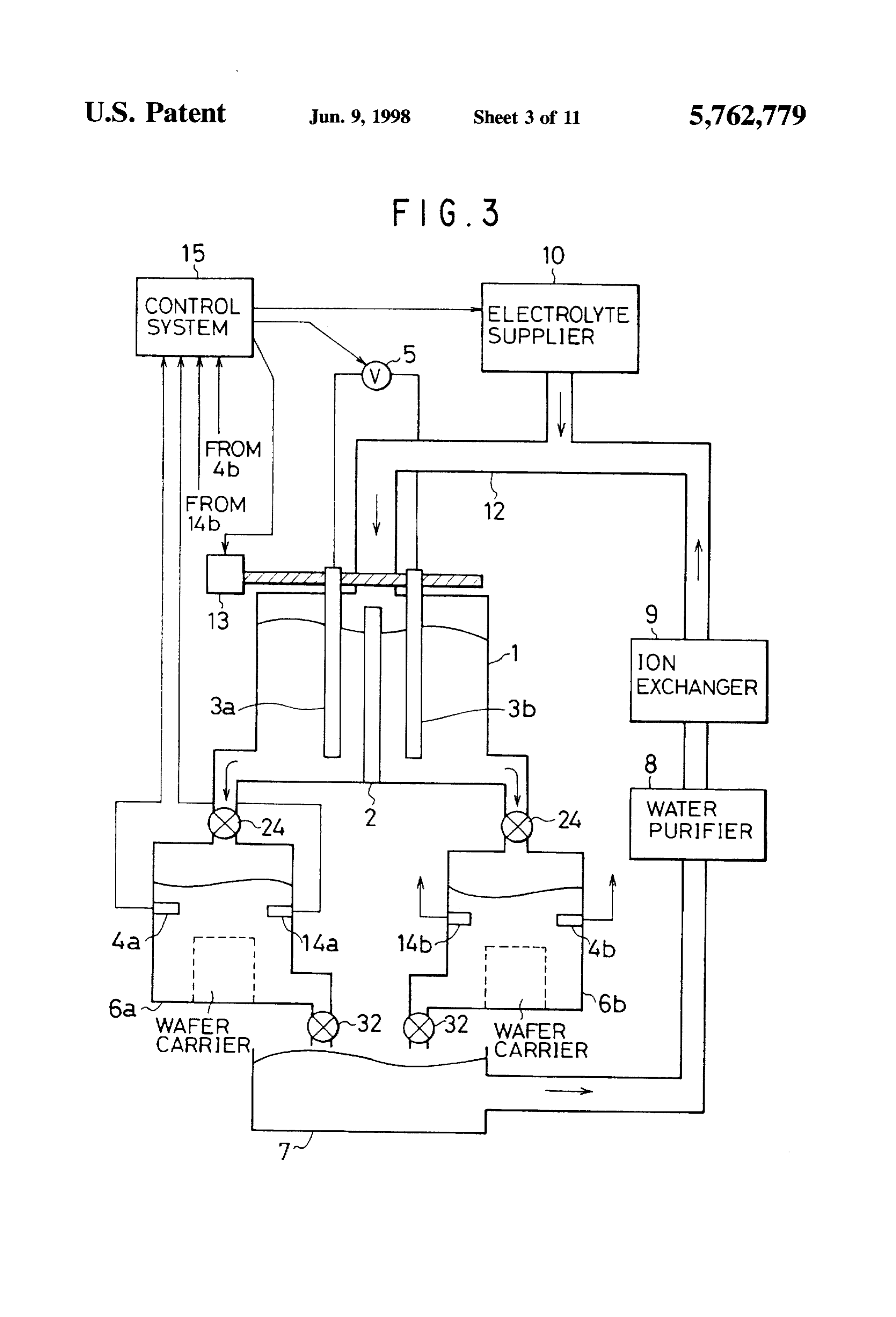
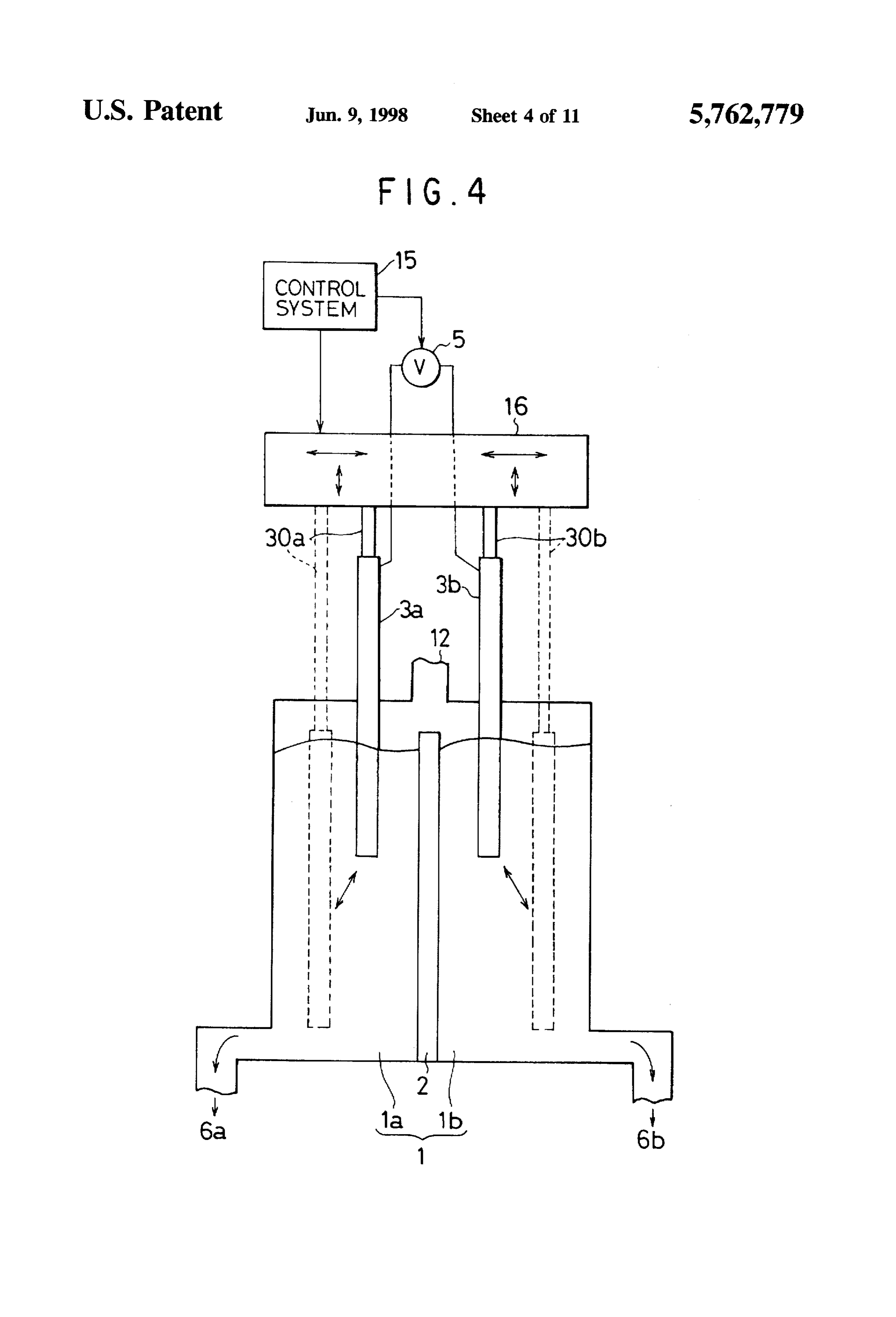
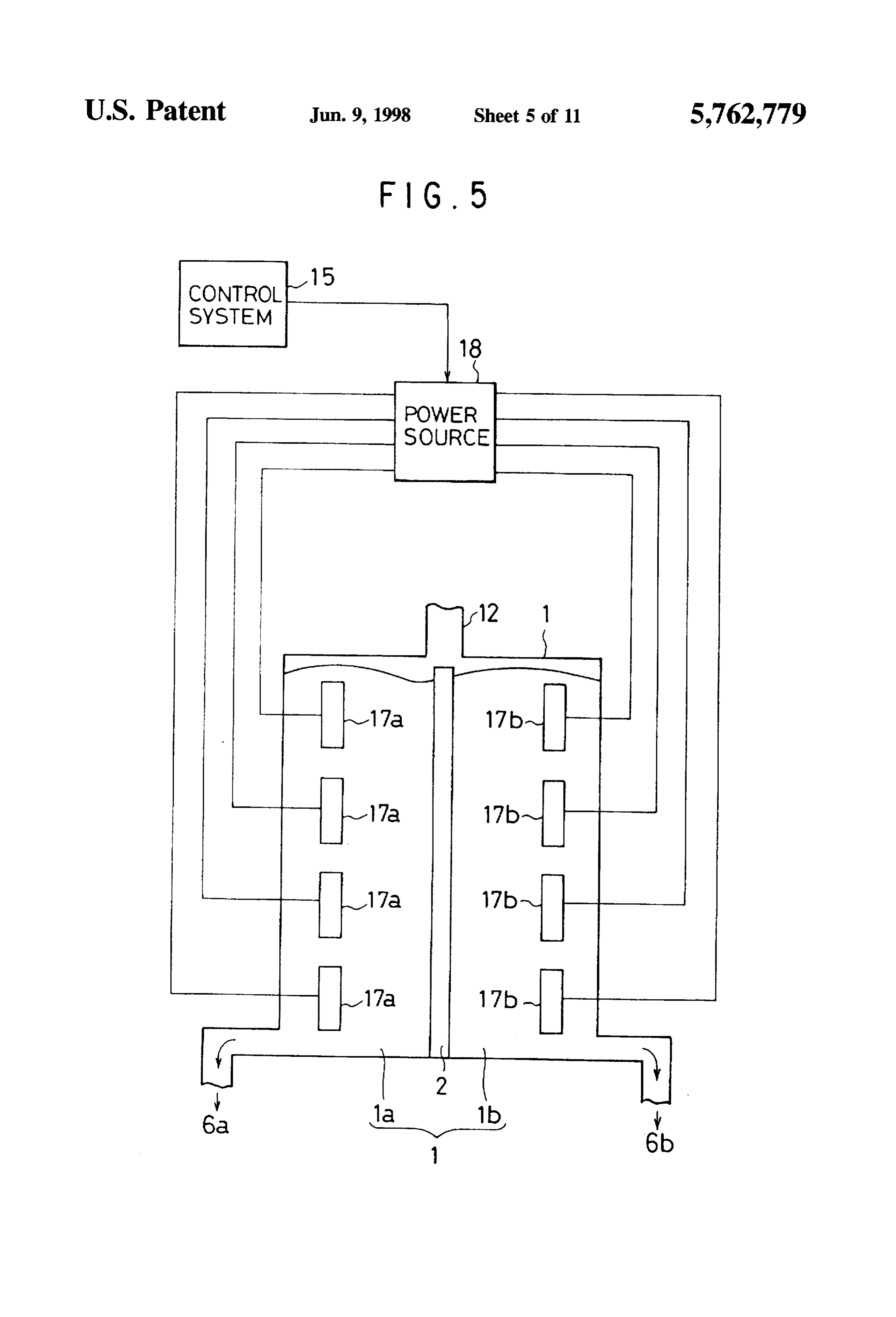
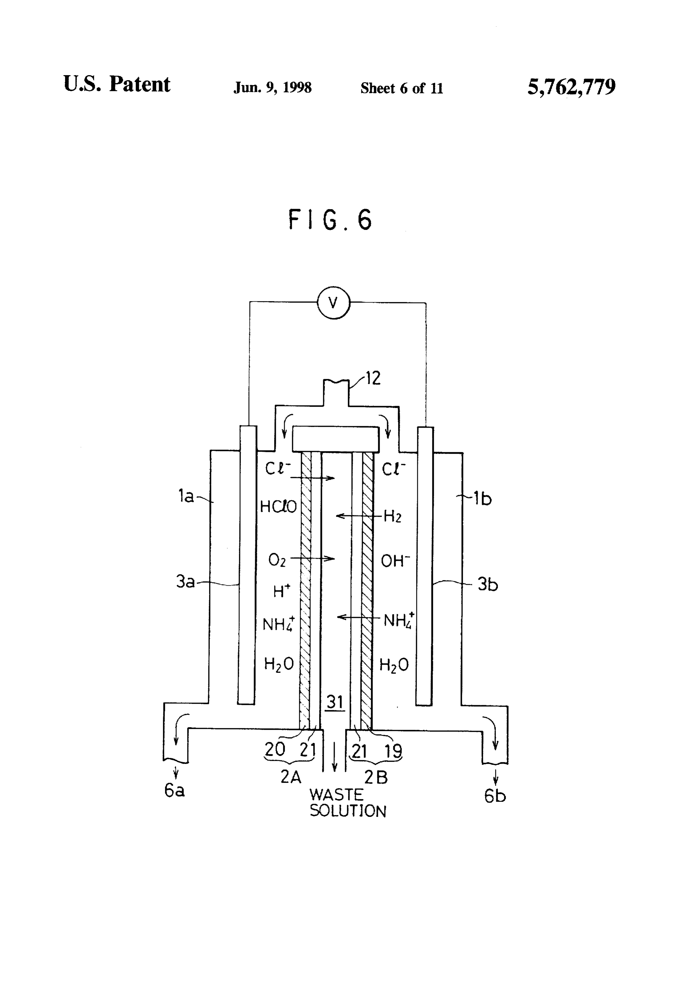
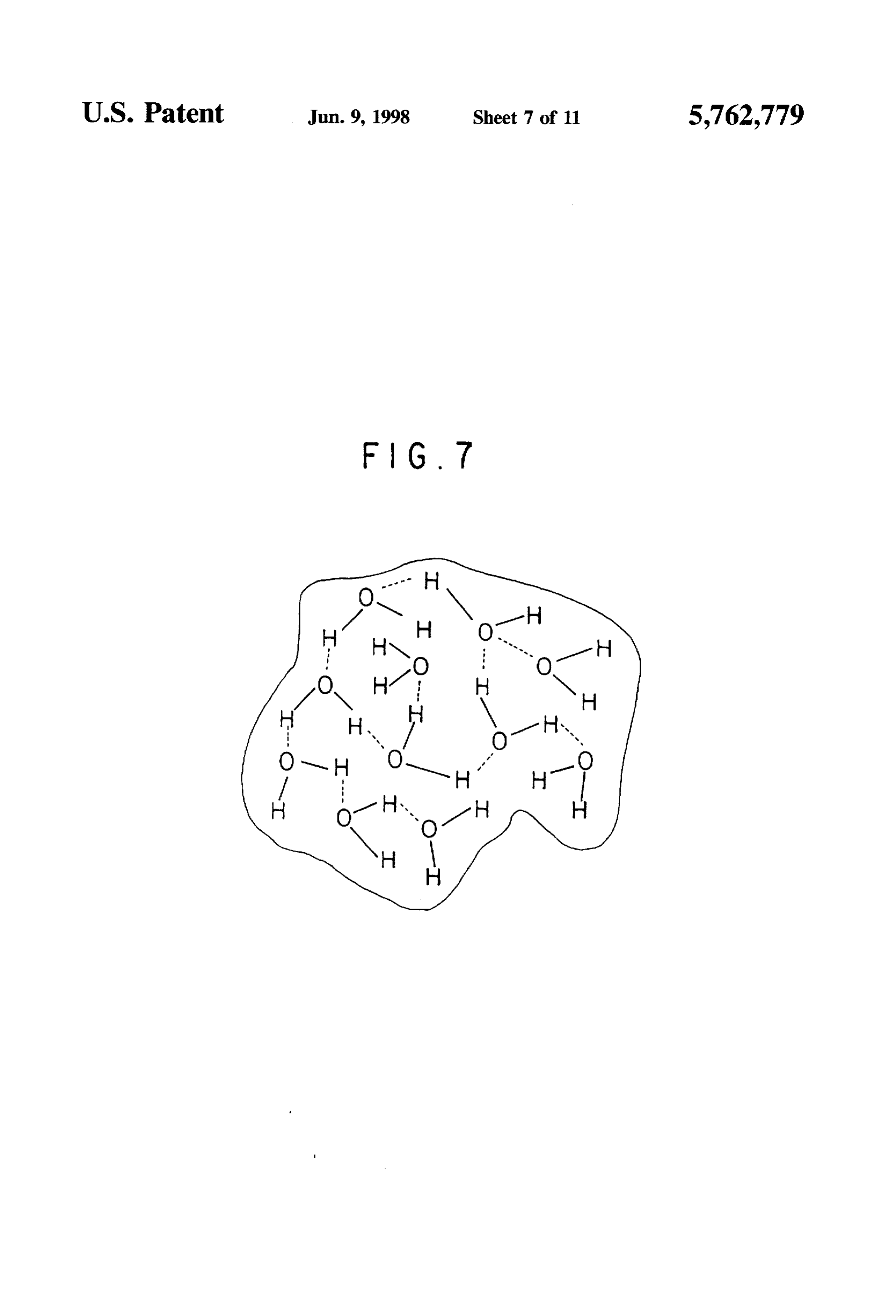
Thus, the temperature of the pure water is controlled to be The advantages obtained by the aforementioned present preferably in the range of 15 to 100 degrees centigrade. more invention will be described hereinbelow. preferably in the range of 20 to 70 degrees centigrade. As explained above, the invention makes it possible to (a) In yet another aspect, the invention provides a method for 30 produce electrolyzed water a short period of time, (b) producing electrolyzed water, including the steps of (a) decrease energy which was conventionally wasted in obtain applying a voltage to electrodes disposed in an electrolytic ing a desired amount of electrolyzed water, (c) enhance the cell containing therein pure water including electrolyte production efficiency of electrolyzed water without applying therein, and (b) applying a magnetic field to the pure water 35 a higher voltage to the electrodes, and (d) produce electro while the step (a) is being carried out. lyzed water with a smaller amount of electrolyte. As a result, A magnetic field applied to the pure water contained in an the invention reduces the use of chemicals and hence waste electrolytic cell deflects H" ion and OH- ion moving per derived from chemicals, and also simplifies the equipment pendicularly to electrodes, in accordance with Fleming's for collection and disposal of waste, to thereby reduce the rule. This phenomenon is explained as the generation of cost while preventing environmental pollution. Lorentz's field. The faster ions flow, the greater strength the The above and other objects and advantageous features of Lorentz's field has. The attenuation of ions occurs at the the present invention will be made apparent from the fol center of the flow of ions. A voltage between electrodes lowing description made with reference to the accompany becomes greater in accordance with the strength of the ing drawings, in which like reference characters designate Lorentz's field with the result that ions are advantageously 45 the same or similar parts throughout the drawings. gathered around an electrode at which the ions are gener BRIEF DESCRIPTION OF THE DRAWTNGS ated. If the attenuation of ions is facilitated, it is possible to remove a partition membrane. FIG. 1 is a schematic view illustrating an apparatus for In still yet another aspect, the invention provides a method wet treatment of semiconductor previously invented by the for producing electrolyzed water, including the steps of (a) 50 inventors.
applying a voltage to electrodes disposed in an electrolytic FIG. 2 is a graph showing successive changes of pH and cell containing therein pure water including electrolyte ORP values.
therein, and (b) applying a pressure to the pure water while FIG. 3 is a schematic view illustrating a wet treatment the step (a) is being carried out. apparatus in accordance with a first embodiment. The pressure is preferably controlled to be variable to 55 FIG. 4 is a schematic view illustrating an electrolytic cell thereby suppress the production of one of anodic electro used in a wet treatment apparatus in accordance with a lyzed water and cathodic electrolyzed water. second embodiment.
When one of anodic electrolyzed water and cathodic FIG. 5 is a schematic view illustrating an electrolytic cell electrolyzed water is to be used or is intended to be increased used in a variation of the second embodiment. in volume, only one of them can be produced by optimizing pressure and/or temperature of electrolyzed pure water. FIG. 6 is a schematic view illustrating an electrolytic cell Thus, it is possible to selectively increase the production of used in a wet treatment apparatus in accordance with a third a desired one of anodic and cathodic electrolyzed water, and embodiment.
thus to reduce the production of the other. FIG. 7 is a schematic view illustrating a cluster of water In a further aspect, the invention provides a method for 65 molecules.
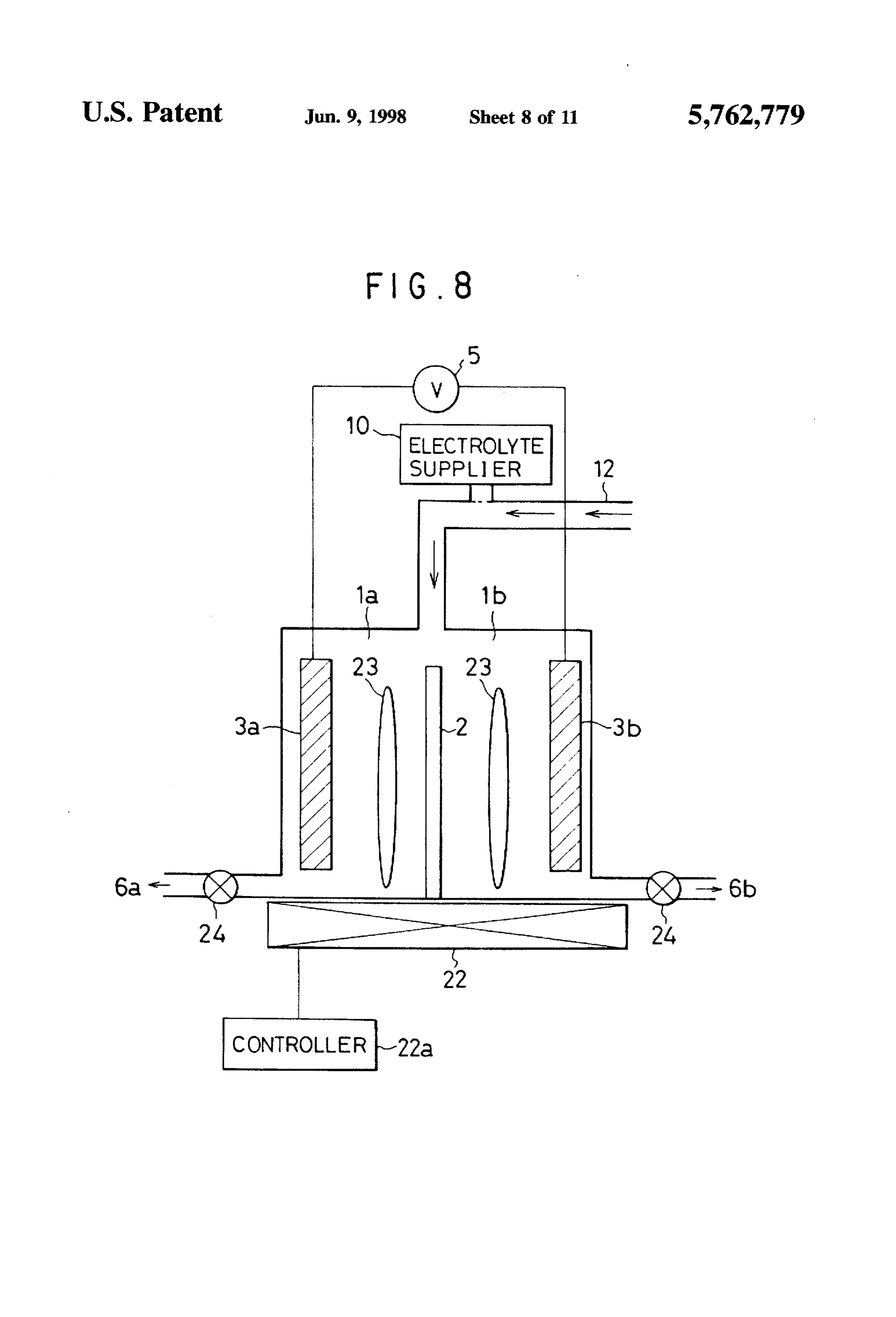
producing electrolyzed water, including the steps of (a) FIG. 8 is a schematic view illustrating a wet treatment forming first and second electrolytic cells so that one of the apparatus in accordance with a fourth embodiment.
Page 17
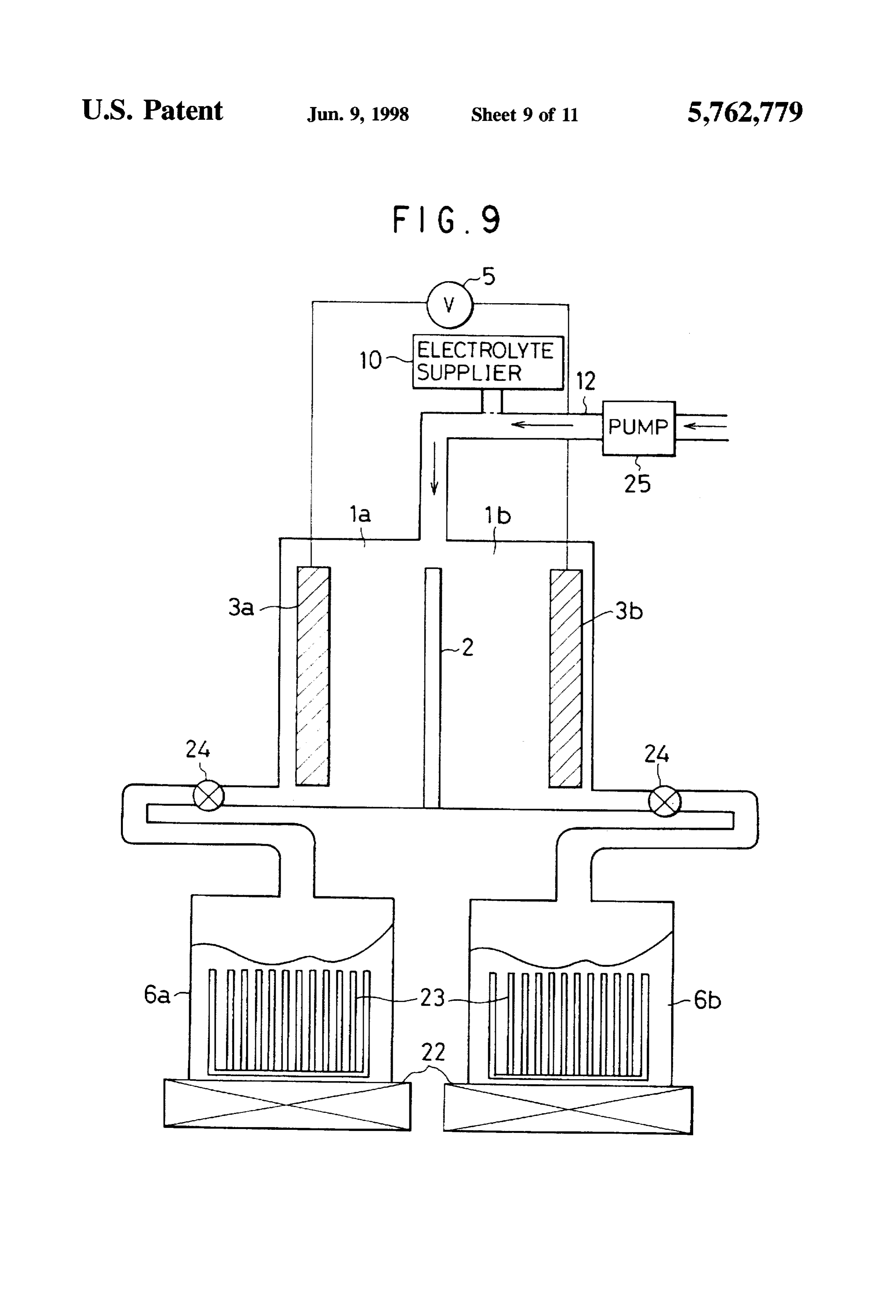
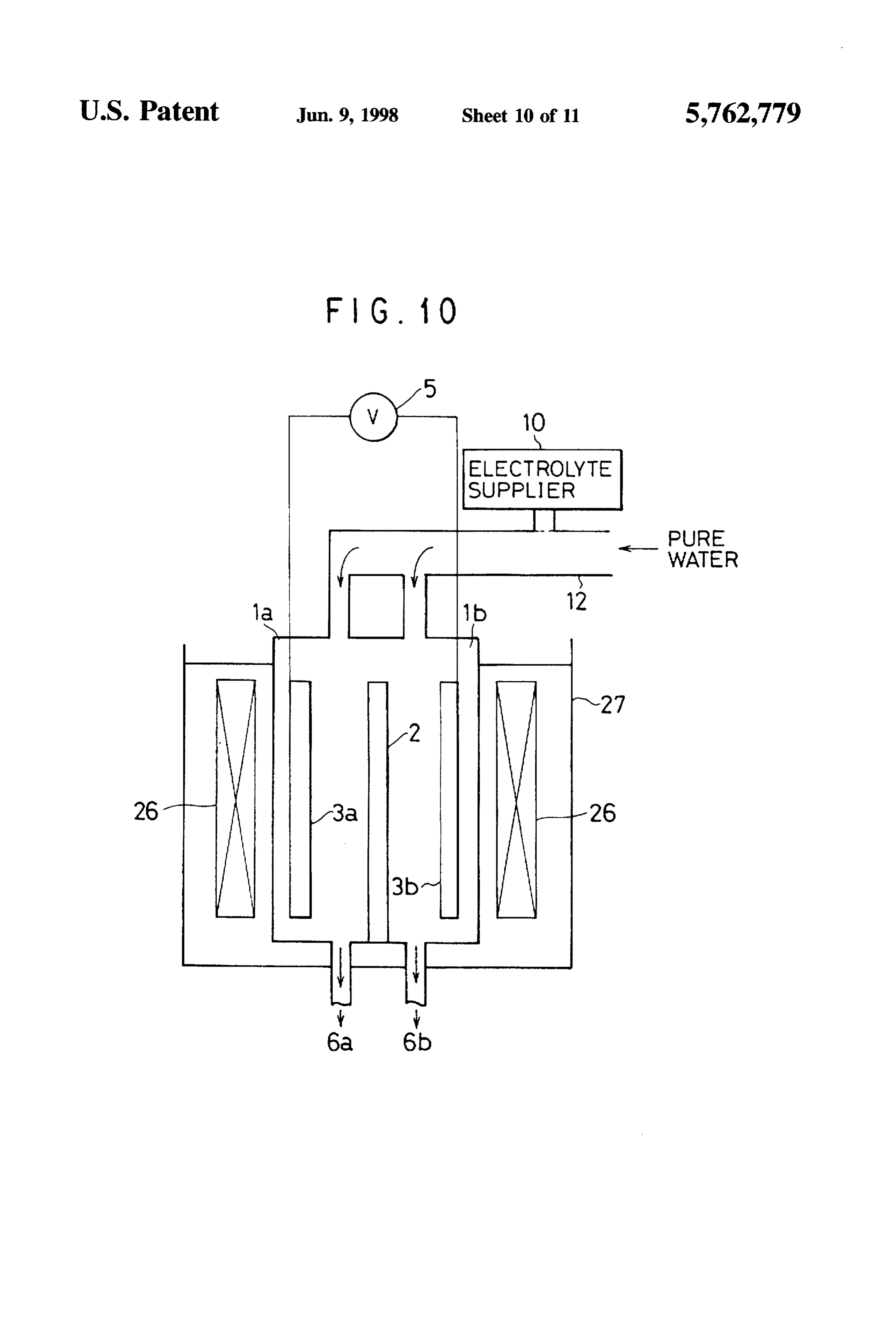
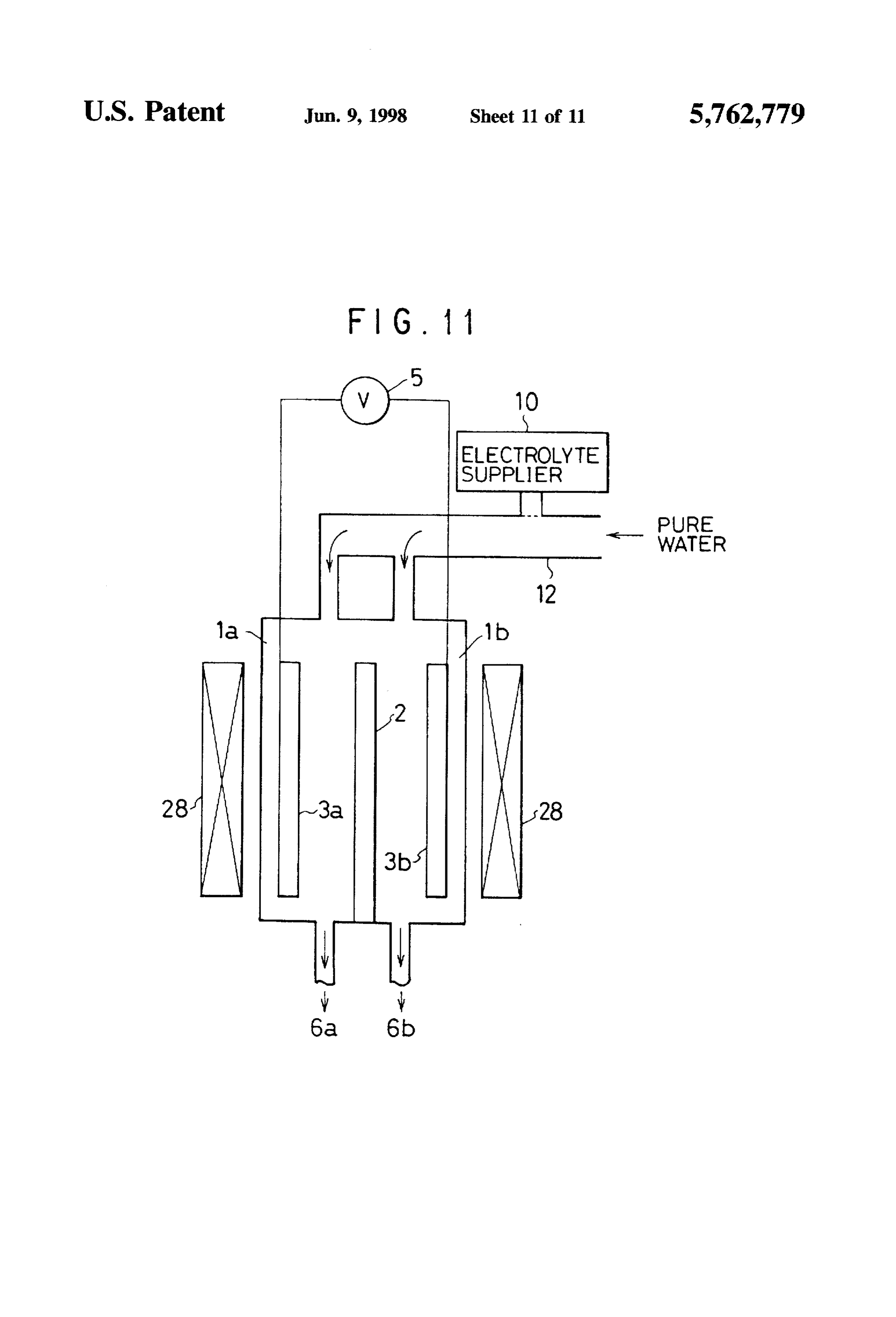
FIG. 9 is a schematic view illustrating a wet treatment mately 3 to 300 V is applied to the electrodes, because it is apparatus in accordance with a fifth embodiment. necessary to apply a voltage equal to a sum of the ideal FIG. 10 is a schematic view illustrating a wet treatment electrolysis voltage and a voltage corresponding to a resis apparatus in accordance with a sixth embodiment. tance of bulk water. It is preferable to apply a voltage in the FIG. 11 is a schematic view illustrating a wet treatment range of 10 to 50 V because, under such a range of voltage. apparatus in accordance with a seventh embodiment. the electrolysis speed can be easily controlled. When a
DESCRIPTION OF THE PREFERRED
voltage is to be applied, if a voltage is gradually increased,
EMBODIMENTS it is possible to prevent an electrical current from suddenly running at the start of electrolysis, thereby fatigue of the
Preferred embodiments in accordance with the present O electrodes can be prevented. Once electrolysis has started, invention will be explained hereinbelow with reference to ions derived from the electrolyte and pure water freely move drawings. in the electrolyzed water, and thus the resistivity is decreased Embodiment 1 to approximately one-tenth relative to the initial resistivity. Hereinbelow will be explained a first embodiment in Then, the electrode mover 13 increases a distance between accordance with the invention with reference to FIG. 3. In 15 the electrodes 3a, 3b to 6 cm in order to attractions around FIG. 3, elements which correspond to those in FIG. 1 have each of the electrodes at which the ions are generated. Even been provided with the same reference numerals. and hence if a distance between the electrodes is increased by ten are not explained in detail. times, the applied voltage remains the same as the voltage The anode 3a and cathode 3b made of platinum (Pt) are having been applied at the start of electrolysis, and hence it connected to an electrode mover 13. The electrode mover 13 is possible to carry out electrolysis without raising the is designed to move simultaneously both of the anode 3a and voltage applied to the electrodes.
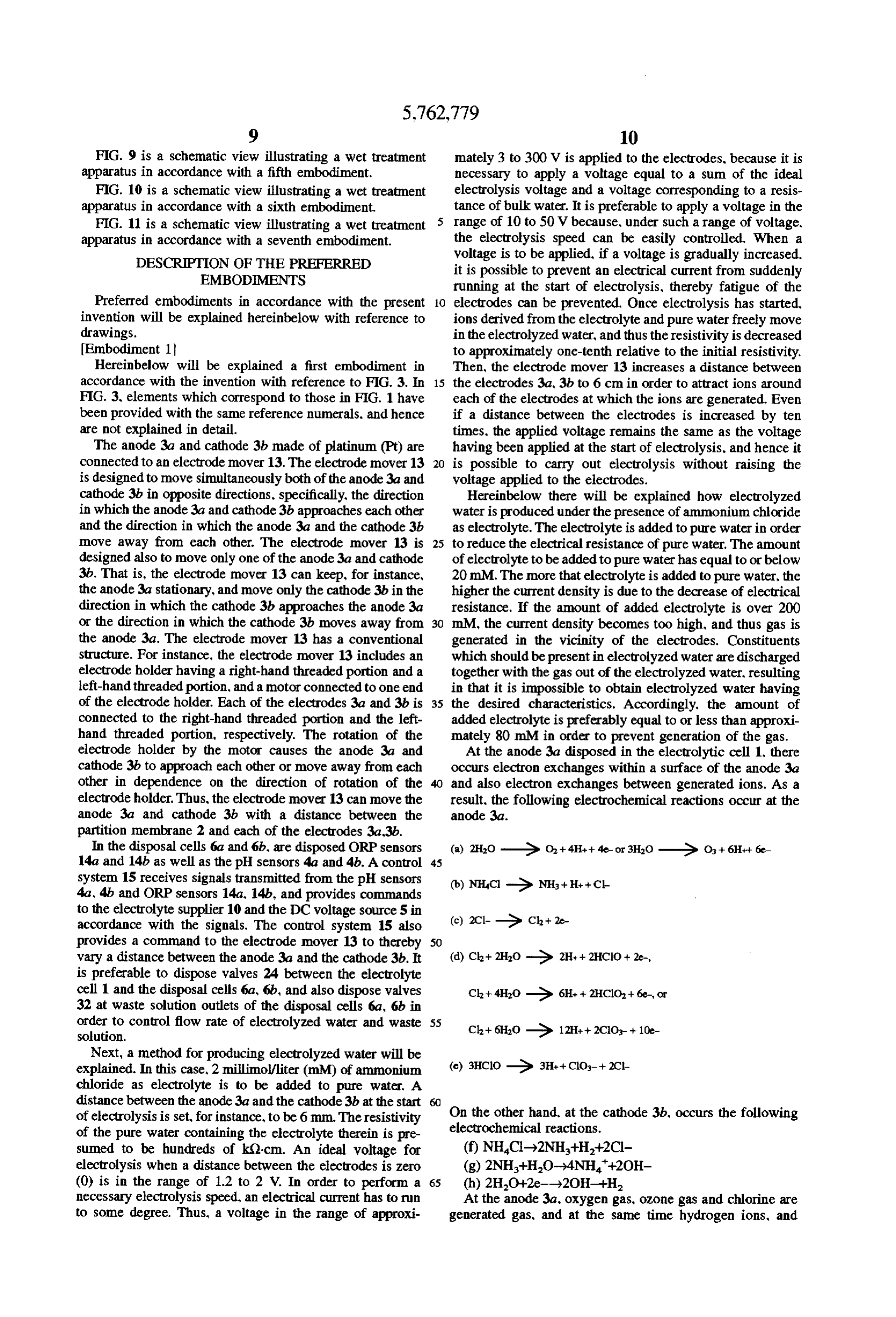
cathode 3b in opposite directions. specifically, the direction Hereinbelow there will be explained how electrolyzed in which the anode 3a and cathode 3b approaches each other water is produced under the presence of ammonium chloride and the direction in which the anode 3a and the cathode 3b as electrolyte. The electrolyte is added to pure water in order move away from each other. The electrode mover 13 is 25 to reduce the electrical resistance of pure water. The amount designed also to move only one of the anode 3a and cathode of electrolyte to be added to pure water has equal to or below 3b. That is, the electrode mover 13 can keep, for instance, 20 mM. The more that electrolyte is added to pure water, the the anode 3a stationary, and move only the cathode 3b in the higher the current density is due to the decrease of electrical direction in which the cathode 3b approaches the anode 3a resistance. If the amount of added electrolyte is over 200 or the direction in which the cathode 3b moves away from mM, the current density becomes too high, and thus gas is the anode 3a. The electrode mover 13 has a conventional generated in the vicinity of the electrodes. Constituents structure. For instance, the electrode mover 13 includes an which should be present in electrolyzed water are discharged electrode holder having a right-hand threaded portion and a together with the gas out of the electrolyzed water, resulting left-hand threaded portion, and a motor connected to one end in that it is impossible to obtain electrolyzed water having of the electrode holder. Each of the electrodes 3a and 3b is 35 the desired characteristics. Accordingly, the amount of connected to the right-hand threaded portion and the left added electrolyte is preferably equal to or less than approxi hand threaded portion, respectively. The rotation of the mately 80 mM in order to prevent generation of the gas. electrode holder by the motor causes the anode 3a and At the anode 3a disposed in the electrolytic cell 1, there cathode 3b to approach each other or move away from each occurs electron exchanges within a surface of the anode 3a other in dependence on the direction of rotation of the and also electron exchanges between generated ions. As a electrode holder. Thus, the electrode mover 13 can move the result, the following electrochemical reactions occur at the anode 3a and cathode 3b with a distance between the anode 3a.
partition membrane 2 and each of the electrodes 3a,3b.
In the disposal cells 6a and 6b, are disposed ORP sensors 14a and 14b as well as the pH sensors 4a and 4b. A control 45 system 15 receives signals transmitted from the pH sensors 4a, 4b and ORP sensors 14a, 14b, and provides commands to the electrolyte supplier 10 and the DC voltage source 5 in accordance with the signals. The control system 15 also provides a command to the electrode mover 13 to thereby vary a distance between the anode 3a and the cathode 3b. It is preferable to dispose valves 24 between the electrolyte cell 1 and the disposal cells 6a, 6b, and also dispose valves 32 at waste solution outlets of the disposal cells 6a, 6b in order to control flow rate of electrolyzed water and waste 55 solution.
Next, a method for producing electrolyzed water will be explained. In this case. 2 millimol/liter (mM) of ammonium chloride as electrolyte is to be added to pure water. A distance between the anode 3a and the cathode 3b at the start of electrolysis is set, for instance, to be 6 mm. The resistivity On the other hand, at the cathode 3b, occurs the following of the pure water containing the electrolyte therein is pre electrochemical reactions.
sumed to be hundreds of k0-cm. An ideal voltage for electrolysis when a distance between the electrodes is zero (0) is in the range of 1.2 to 2 V. In order to perform a 65 (h) 2H2O+2e--)2OH--H necessary electrolysis speed, an electrical current has to run At the anode 3a, oxygen gas, ozone gas and chlorine are to some degree. Thus, a voltage in the range of approxi generated gas, and at the same time hydrogen ions, and
Page 18
hypochlorite ions, chlorite ions and chlorate ions that is ions contrary, in order to decrease the production of electrolyzed composed of a combination of chlorine and oxygen water, the anode 3a and the cathode 3b are raised up in the (hereinafter, referred to as ClOx-), and chloride ions also pure water to thereby decrease the soaking area of the generate. Since ClOx- is the most active among them, it electrodes 3a, 3b.
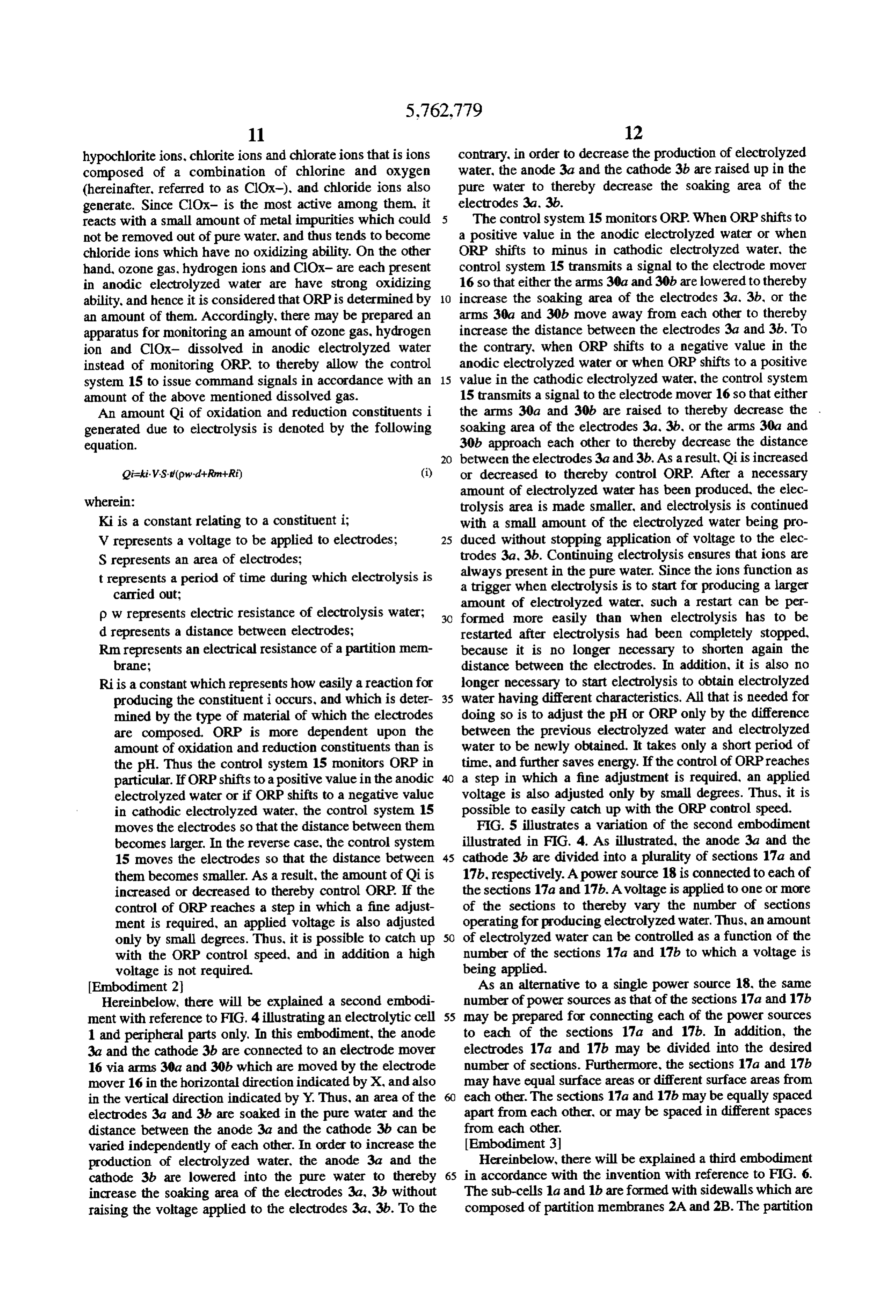
reacts with a small amount of metal impurities which could The control system 15 monitors ORP. When ORP shifts to not be removed out of pure water, and thus tends to become a positive value in the anodic electrolyzed water or when chloride ions which have no oxidizing ability. On the other ORP shifts to minus in cathodic electrolyzed water, the hand, ozone gas, hydrogen ions and ClOx- are each present control system 15 transmits a signal to the electrode mover in anodic electrolyzed water are have strong oxidizing 16 so that either the arms 30a and 30b are lowered to thereby ability, and hence it is considered that ORP is determined by O increase the soaking area of the electrodes 3a, 3b, or the an amount of them. Accordingly, there may be prepared an arms 30a and 30b move away from each other to thereby apparatus for monitoring an amount of ozone gas, hydrogen increase the distance between the electrodes 3a and 3b. To ion and ClOx- dissolved in anodic electrolyzed water the contrary, when ORP shifts to a negative value in the instead of monitoring ORP to thereby allow the control anodic electrolyzed water or when ORP shifts to a positive system 15 to issue command signals in accordance with an 15 value in the cathodic electrolyzed water, the control system amount of the above mentioned dissolved gas. 15 transmits a signal to the electrode mover 16 so that either An amount Qi of oxidation and reduction constituents i the arms 30a and 30b are raised to thereby decrease the . generated due to electrolysis is denoted by the following soaking area of the electrodes 3a. 3b, or the arms 30a and equation. 30b approach each other to thereby decrease the distance 20 between the electrodes 3a and 3b. As a result, Qi is increased or decreased to thereby control ORP. After a necessary wherein:
amount of electrolyzed water has been produced, the elec trolysis area is made smaller, and electrolysis is continued
Ki is a constant relating to a constituent i; with a small amount of the electrolyzed water being pro V represents a voltage to be applied to electrodes; 25 duced without stopping application of voltage to the elec S represents an area of electrodes; trodes 3a, 3b. Continuing electrolysis ensures that ions are t represents a period of time during which electrolysis is aalways present in the pure water. Since the ions function as trigger when electrolysis is to start for producing a larger carried out; amount of electrolyzed water, such a restart can be per p w represents electric resistance of electrolysis water; 30 formed more easily than when electrolysis has to be d represents a distance between electrodes; restarted after electrolysis had been completely stopped, Rm represents an electrical resistance of a partition men because it is no longer necessary to shorten again the brane; distance between the electrodes. In addition, it is also no Riis a constant which represents how easily a reaction for longer necessary to start electrolysis to obtain electrolyzed producing the constituenti occurs, and which is deter 35 water having different characteristics. All that is needed for mined by the type of material of which the electrodes doing so is to adjust the pH or ORP only by the difference are composed. ORP is more dependent upon the between the previous electrolyzed water and electrolyzed amount of oxidation and reduction constituents than is water to be newly obtained. It takes only a short period of the pH. Thus the control system 15 monitors ORP in time, and further saves energy. If the control of ORPreaches particular. If ORP shifts to a positive value in the anodic a step in which a fine adjustment is required, an applied electrolyzed water or if ORP shifts to a negative value voltage is also adjusted only by small degrees. Thus, it is in cathodic electrolyzed water, the control system 15 possible to easily catch up with the ORP control speed. moves the electrodes so that the distance between them FIG. 5 illustrates a variation of the second embodiment becomes larger. In the reverse case, the control system illustrated in FIG. 4. As illustrated, the anode 3a and the 15 moves the electrodes so that the distance between 45 cathode 3b are divided into a plurality of sections 17a and them becomes smaller. As a result, the amount of Qi is 17b, respectively. A power source 18 is connected to each of increased or decreased to thereby control ORP. If the the sections 17a and 17b. A voltage is applied to one or more control of ORP reaches a step in which a fine adjust of the sections to thereby vary the number of sections ment is required, an applied voltage is also adjusted operating for producing electrolyzed water. Thus, an amount only by small degrees. Thus, it is possible to catch up 50 of electrolyzed water can be controlled as a function of the with the ORP control speed, and in addition a high number of the sections 17a and 17b to which a voltage is voltage is not required. being applied.
Embodiment 2 As an alternative to a single power source 18, the same Hereinbelow, there will be explained a second embodi number of power sources as that of the sections 17a and 17b ment with reference to FIG. 4 illustrating an electrolytic cell 55 may be prepared for connecting each of the power sources 1 and peripheral parts only. In this embodiment, the anode to each of the sections 17a and 17b. In addition, the 3a and the cathode 3b are connected to an electrode mover electrodes 17a and 17b may be divided into the desired 16 via arms 30a and 30b which are moved by the electrode number of sections. Furthermore, the sections 17a and 17b mover 16 in the horizontal direction indicated by X, and also may have equal surface areas or different surface areas from in the vertical direction indicated by Y. Thus, an area of the each other. The sections 17a and 17b may be equally spaced electrodes 3a and 3b are soaked in the pure water and the apart from each other, or may be spaced in different spaces distance between the anode 3a and the cathode 3b can be from each other, varied independently of each other. In order to increase the Embodiment 3 production of electrolyzed water, the anode 3a and the Hereinbelow, there will be explained a third embodiment cathode 3b are lowered into the pure water to thereby 65 in accordance with the invention with reference to FIG. 6. increase the soaking area of the electrodes 3a, 3b without The sub-cells 1a and 1b are formed with sidewalls which are raising the voltage applied to the electrodes 3a, 3b. To the composed of partition membranes 2A and 2B. The partition
Page 19
membrane 2A and 2B of the sub-cells 1a and 1b face each 22a which controls the temperature of pure water to be in a other and are spaced from each other to thereby form a space desired range during electrolysis. 31 therebetween. The partition membrane 2A of the sub-cell The heater 22 may be disposed in the electrolytic cell 1. 1a is composed of an internal cation exchange membrane 20 As an alternative to the heater 22, various conventional and an external gas-permeable membrane 21, while the heating means may be used such as resistive heating. lamp partition membrane 2B of the sub-cell 1b is composed of an heating and microwaves heating. The heater 22 is controlled internal anion exchange membrane 19 and an external by the controller 22a to keep pure water at a temperature gas-permeable membrane 21. preferably in the range of 15 to 100 degrees centigrade, and In operation, pure water containing electrolyte therein is more preferably in the range of 20 to 70 degrees centigrade. first introduced into each of the sub-cells 1a and 1b. Then, 10 Embodiment 5 a voltage is applied across the anode 3a and cathode 3b. Either anodic electrolyzed water or cathodic electrolyzed Then, pure water in the sub-cells 1a and 1b are electrolyzed, water is selectively used in accordance with the wet treat and then introduced to the disposal cells 6a and 6b. Waste ment. However, there is hardly a case in which both of solution is discharged through the space 31. anodic and cathodic electrolyzed water are to be used. Thus, When ammonium chloride is used as the electrolyte. the 15 though both anodic and cathodic electrolyzed water are aforementioned electrochemical reactions (a) to (e) and (f) produced by electrolysis, one of them which is not to be used to (h) occur at the anode 3a and the cathode 3b, respectively. has conventionally been wasted. In order to selectively Oxygen gas increases H* concentration, but does not have as obtain the desired one and not to produce the other to high an oxidizing ability. On the other hand, ozone gas thereby save such waste, an apparatus in accordance with the increases HA" concentration and has a high oxidizing abil 20 fifth embodiment is designed to be able to vary the pressure ity. When ozone gas is oxidized, ozone gas is decomposed in the sub-cells 1a and 1b of the electrolytic cell 1. In to oxygen gas. If most the of oxygen gas stays in electro accordance with the embodiment, it is possible to efficiently lyzed water, Hion are generated at the anode 3a. H" ion is produce only one of anodic or cathodic electrolyzed water gradually, electrically attracted to the cathode 3b at low independently of the electrolyte added to pure water and the speed. However, the cation exchange membrane 20 impedes 25 voltage applied to the electrodes.
H' ion from moving towards the cathode 3b, and hence H' With reference to FIG. 9, a wet treatment apparatus in ion is densified in the vicinity of the anode 3a. On the other accordance with the invention will be explained hereinbe hand, the anion exchange membrane 21 impedes OH- ion low, Into the electrolytic cell 1, there is introduced ultra-pure generated in the sub-cell 1b from moving towards the anode water having a semiconductor grade through the conduit 12. 3a, and hence OH- ion is densified in the vicinity of the 30 To the conduit 12, there is connected a helium (He) the cathode 3b. pressure pump 25 for providing the pressure in the conduit Embodiment 4 12 with highly pure He gas in order to prevent a counterflow FIG. 7 illustrates a structure of water molecules. A water in the conduit 12 which may occur due to a difference in molecule HO does not exist separately from other water pressure generated when the pressure of the electrolytic cell molecules in water, but exist as a cluster in which several 35 1 is set to be higher than that of the conduit 12. As an water molecules are hydrogen-bonded with each other. alternative to He gas, otherinert gas may be used. However, Accordingly, as is obvious from Table 1 listing molecular He gas is the best choice, because He gas, can provide highly weights (MW) and boiling points of hydrogenated pure gas and He gas does not influence wet treatments. If compounds, water exists a liquid at room temperature and electrolysis is to be carried out with the electrolysis cell 1 has a high boiling point, specifically, approximately 100 kept at a lower pressure than that of the conduit, the He degrees centigrade, unlike other hydrogenated compound pressure pump 25 need not be installed, because there is no such as HS which is active gas at room temperature. In fear of a counterflow. In addition, it is preferable to carry out addition, pure water is considered to a slightly lower boiling wet treatments of semiconductor substrates in a cell other point than that of tap water, because pure water has a smaller than the electrolytic cell 1 in order to avoid the substrates cluster than that of tap water, and is not influenced by 45 from being damaged due to increased or decreased pressure impurities with respect to the raising of a boiling point and in the electrolytic cell 1 during electrolysis. Thus, the the lowering of a freezing point. Electrolyzed water has a disposal cells 6a and 6b are installed separately from the smaller cluster than that of pure water, since a cluster is electrolytic cell 1 to be able to provide electrolyzed water decomposed by electrolysis and H ion and OH- ion are produced in the electrolytic cell 1 to the disposal cells 6a and generated. 50 6b which are maintained under atmospheric pressure. If ammonium chloride is used as the electrolyte, there
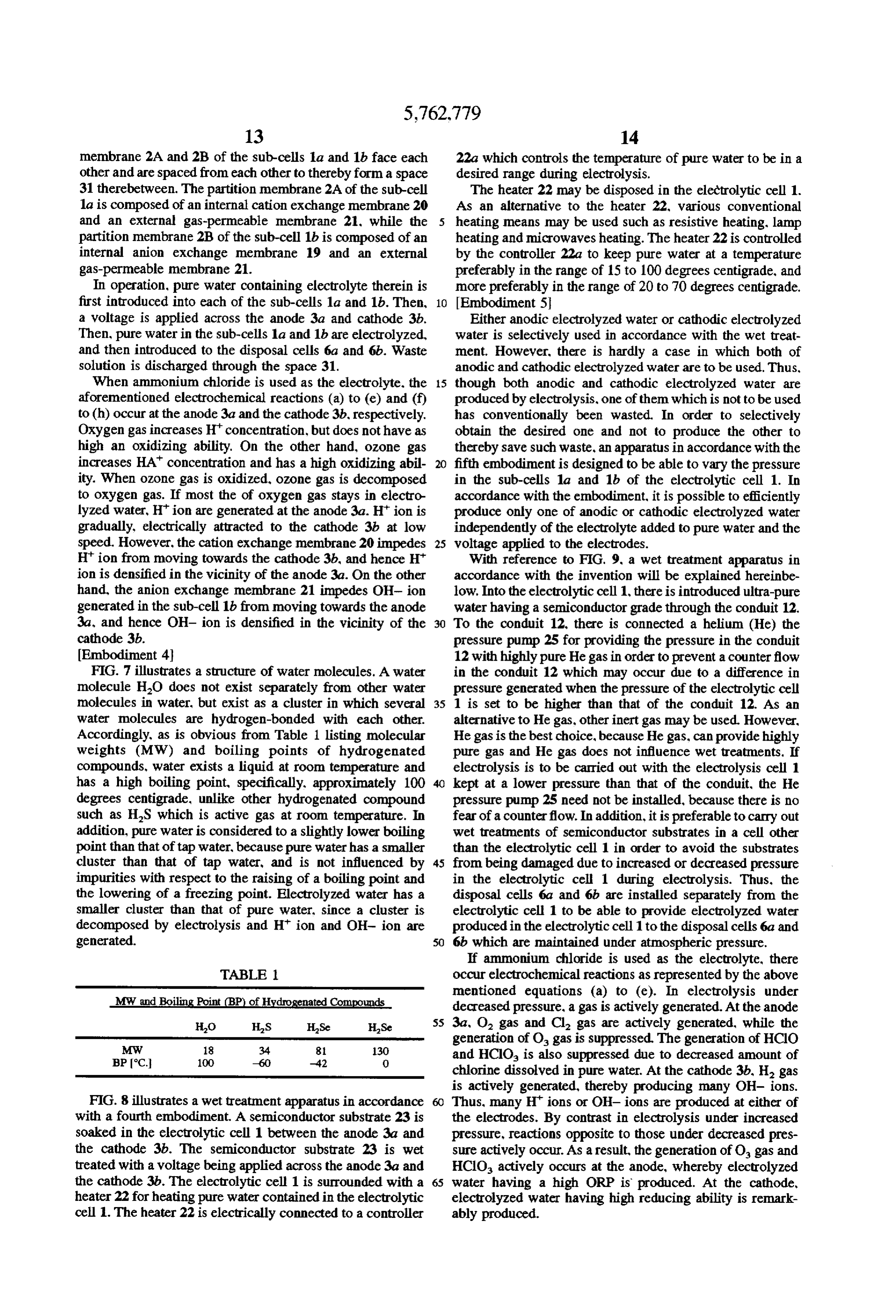
TABLE 1. occur electrochemical reactions as represented by the above MW and Boiling Point (BP) of Hydrogenated Compounds mentioned equations (a) to (e). In electrolysis under decreased pressure, a gas is actively generated. At the anode 55 3a, O gas and Cl gas are actively generated, while the
generation of O gas is suppressed. The generation of HCIO
BPC. 100 -60 -42 O and HCIO is also suppressed due to decreased amount of chlorine dissolved in pure water. At the cathode 3b, H gas is actively generated, thereby producing many OH- ions.
FIG. 8 illustrates a wet treatment apparatus in accordance Thus, many H ions or OH- ions are produced at either of with a fourth embodiment. A semiconductor substrate 23 is the electrodes. By contrast in electrolysis under increased soaked in the electrolytic cell 1 between the anode 3a and pressure, reactions opposite to those under decreased pres the cathode 3b. The semiconductor substrate 23 is wet sure actively occur. As a result, the generation of O gas and treated with a voltage being applied across the anode 3a and HCIO actively occurs at the anode, whereby electrolyzed the cathode 3b. The electrolytic cell 1 is surrounded with a 65 water having a high ORP is produced. At the cathode, heater 22 for heating pure water contained in the electrolytic electrolyzed water having high reducing ability is remark cell 1. The heater 22 is electrically connected to a controller ably produced.
Page 20
Embodiment 6 strong electrolyte containing halogen therein, it is possible FIG. 10 illustrates a wet treatment apparatus in accor to apply further lower voltage to the electrodes than the case dance with a sixth embodiment. Around the electrolytic cell in which a weak electrolyte is selected Furthermore, com 1, there is disposed an ultrasonic wave cell 27 in which pared to the case wherein electrolyte is used, the amount of ultrasonic wave generators 26 are installed. Electrolysis is electrolyte to be added to pure water can be decreased, and carried out in the electrolytic cell 1 with ultrasonic waves thus the use of chemicals can be further decreased. having approximately 1 MHz of frequency being radiated The invention makes it also possible to obtain most of the from the ultrasonic wave generators 26 to pure water to be electrolyzed water in a short period of time without applying electrolyzed present in the electrolytic cell 1. a higher voltage to the electrodes by designing a variable If water is provided from an outside source with energy O electrolysis area. Thus, it is possible to carry out a desired such as ultrasonic wave oscillation, molecule movement is treatment before ORP changes as times go by. As mentioned made more active with the result that a cluster, which in the second embodiment, the electrodes are driven by a hydrogen-bonds several water molecules with each other, is pair of arms which are movable independently of each other decomposed. Thus, a cluster becomes smaller and smaller. in the horizontal and vertical directions. Since the distance Since electrolyzed water is water in which a cluster is 15 between the electrodes can be varied only by the movable decomposed and also in which H ion and OH- ion are arms, the wet treatment apparatus can be compact-sized. produced, the provision of ultrasonic wave oscillation dur Furthermore, the embodiment in which the electrodes are ing electrolysis facilitates the decomposition of a cluster, divided into a plurality of sections to which a voltage is to thereby electrolysis can be easily carried out. be applied makes it possible to vary the electrolysis area Embodiment 7 with the electrodes being soaked in the electrolyzed water. FIG. 11 illustrates a wet treatment apparatus in accor Thus, the embodiment ensures that the electrodes are not dance with a seventh embodiment. Around the electrolytic exposed to the atmosphere and hence are not polluted. In cell 1. there is disposed a plurality of magnetic field applying addition, it is possible to instantaneously vary the electroly devices 28 comprising a permanent magnet, an electromag sis area to thereby provide high controllability. If the pro net or a combination thereof. If H ion and OH- ion 25 duction of electrolyzed water is continued with the elec produced through electrolysis flow in a certain direction in trolysis area kept small, ions are always present in the the electrolytic cell 1, on applying a magnetic field to the electrolyzed water. Since such ions function as a trigger for ion's flow, the ion is deflected in accordance with the restarting electrolysis, it is easier to restart electrolysis than Fleming's left-hand rule. Specifically, H ion and OH- ion in the case in which electrolysis had been completely are deflected in opposite directions. This phenomenon is stopped and then electrolysis has to be started again. because generally explained as the generation of Lorentz's field. The it is no longer necessary to shorten the distance between the electrolyzed water is made to flow from top to bottom in the electrodes again. In addition, it is also no longer necessary electrolytic cell 1, and thus the flow of H" ion and OH- ion to start electrolysis for obtaining electrolyzed water having are produced. If the north pole of the magnet 28 is disposed different characteristics. All that is needed for doing so is to beyond a plane of FIG. 11 and the south pole of the magnet 35 adjust the pH or ORP by setting up a difference between the 28 is disposed short of a plane of FIG. 11, the flow of Hion previous electrolyzed water and the electrolyzed water to be is deflected toward the anode 3a and the flow of OH- ion is newly obtained. It takes only a short period of time, and deflected toward the cathode 3b. The strength of Lorentz's further saves energy. If the control of ORP reaches a step in field is dependent on a speed of the ion's flow. In general, the which a fine adjustment is required, the applied voltage is faster the ion flows, the greater strength the field can have. also adjusted only by small degrees. Thus, it is possible to A voltage between the electrodes 3a and 3b becomes greater easily catch up with the ORP control speed and efficiently in accordance with the strength of the field, and the attenu obtain electrolyzed water without applying a higher voltage ation of ions occur at the center of the flow. Thus, around to the electrodes.
each of the electrodes 3a and 3b, there are gathered H" ion In the third embodiment, the partition membrane is com and OH- ion to thereby increase H ion concentration and 45 posed of a combination of an anion exchange membrane or OH- ion concentration in the vicinity of the anode 3a and a cation exchange membrane and a gas-permeable thin the cathode 3b, respectively. Accordingly, it is not necessary membrane. Thus, it is possible to discharge excessive oxy to dispose the partition membrane 2 in a certain electrolysis gen gas and hydrogen gas out of the electrolyzed water, and condition. hence the production of a hydrogen ion and oxidation Each of the preferred embodiments has been explained 50 reaction are not prevented, and gases are not allowed to stay independently of each other, however, it should be noted that in the electrolyzed water, whereby the electrolyzed water two or more of the embodiments may be used in combina can be efficiently obtained. Thus, since it is no longer tion. Such a combination of the embodiments provides necessary to employ excessive electrical power and time for higher electrolysis efficiency than single use of the embodi producing the electrolyzed water, a higher productivity can ments. In the combination use, it is preferable that each of 55 be obtained. In addition, since the anion exchange mem the physical energy applying means such as the ultrasonic brane is disposed in the sub-cell in which the anode 3a is wave generator 26 used in the sixth embodiment is to be disposed and the cation exchange membrane is disposed in connected to and be controlled by a control system so that the sub-cell in which the cathode 3b is disposed, and hence a pH value, ORP and an amount of dissolved gas are kept in the H ion cannot pass through the anion exchange mem a desired range. brane and the OH- ion cannot pass through the cation As has been explained with reference to the preferred exchange membrane, it is possible to efficiently concentrate embodiments, the invention makes it possible to raise a the H" ion in the sub-cell in which the anode is disposed, and speed of production of H ion, OH- ion, oxidizing material also efficiently concentrate the OH- ion in the sub-cell in and reducing material to thereby enhance the production which the cathode is disposed.
efficiency without applying a higher voltage to the elec 65 It is difficult to decompose a water cluster at low tem trodes by designing a distance between the electrodes to be perature. The fourth embodiment in which the heater 22 is variable. In addition, since the electrolyte is selected among disposed around the electrolytic cell 1 can easily decompose
Page 21
a water cluster to thereby make it possible to easily carry out partition membrane. If electrolysis is carried out and only electrolysis. In addition, the raised temperature allows oxy oxygen gas and hydrogen gas are produced it is not neces gen gas and hydrogen gas to easily volatilize, and hence the sary to provide a partition membrane. In order to use the reaction for producing the H" ion and the OH- ion are apparatus for wet treatment, it is absolutely necessary to facilitated. However, oxidizing material produced at the 5 produce H" ion and OH- ion, and hence it is not allowed to anode such as ClOx- and ozone gas has a high vapor remove the partition membrane. However, the invention pressure, and hence is volatilized at a temperature in the makes it possible not to use the partition membrane by range of 80 to 100 degrees centigrade. Ammonium gas applying a magnetic field to the electrolyzed water, and which is a reducing material produced at the cathode and without hence it is now possible to produce H ion and OH- ion which contributes to the production of hydrogen gas and 10 partition preventing membrane.
the flow of ion passing through the
Thus, the electrolysis efficiency can
OH- ion tends to be volatilized. Thus, if the temperature is remarkably be enhanced.
raised too the oxidizing material and reducing material are speed of electrolyzed waterIn and/or addition, by controlling the flow disadvantageously lost. In view of these matters, the tem of magnetic field applied to the the magnetic flux density electrolyzed water, it is perature is preferably in the range of approximately 15 to possible to control the pH value and the concentration of 100 degrees centigrade, and more preferably in the range of oxidizing and reducing material which is dependent on ORP
approximately 20 to 70 degrees centigrade. Thus, by opti Thus, it is possible to obtain a high concentration of elec mizing the temperature, it is possible to enhance the effi trolyzed water without increasing the use of chemicals, the ciency of production of electrolyzed water. voltage applied to the electrodes and the time required for In accordance with the fifth embodiment in which the electrolysis. As a result, the throughput can be remarkably pressure in the electrolytic cell 1 is variable, it is possible to 20 enhanced.
carry out electrolysis with the sub-cells 1a and 1b being While the present invention has been described in con pressurized or depressurized independently of each other. nection with certain preferred embodiments, it is to be Thus, it is possible to produce a larger amount of anodic understood that the subject matter encompassed by way of electrolyzed water than cathodic electrolyzed water by the present invention is not to be limited to those specific selectively causing reactions in the sub-cell 1a in which the 25 embodiments. On the contrary, it is intended for the subject anode 3a is disposed, or produce a larger amount of cathodic matter of the invention to include all alternatives, modifi electrolyzed water than anodic electrolyzed water by selec cations and equivalents as can be included within the spirit tively causing reactions in the sub-cell 1b in which the andWhat scope of the following claims. is claimed is:
cathode 3b is disposed. Hence, it is possible to efficiently obtain one of anodic and cathodic electrolyzed water, and 30 1. A method for producing electrolyzed water in a process reduce the production of the other. Furthermore, it is also for treating a semiconductor wafer with electrolyzed water, possible to control the flow rate of electrolyzed water comprising the steps of:
without dependency on the amount of electrolyte added to (a) adding an electrolyte into pure water purified through the pure water and the voltage applied to the electrodes, and an ion exchanger to produce pure water containing an hence the throughput can be enhanced and the use of 35 electrolyte;
chemicals can be reduced. (b) producing electrolyzed water by applying a voltage to The sixth embodiment having the ultrasonic wave gen electrodes disposed in an electrolytic cell containing erator 26 provided therein facilitates the decomposition of a pure water and electrolyte therein; water cluster, and hence also facilitates the production of H" (c) controlling the temperature of said pure water during ion and OH- ion, with the result of enhancement of the the step of producing electrolyzed water by applying efficiency of production of electrolyzed water. The degas heating means to the outside of said electrolytic cell to ification of oxygen gas and hydrogen gas is also facilitated, maintain said pure water at a temperature in the range A combination of the ultrasonic wave generating means and of 20°-70° C.; and (d) applying said electrolyzed water the gas-permeable thin membrane could further facilitate to the semiconductor wafer.
electrolysis. 45 2. The method as recited in claim 1, wherein said tem In accordance with the seventh embodiment in which a perature of said pure water is controlled to be in the range magnetic field applying means is provided, it is possible to of 20 to 70 degrees centigrade. concentrate H" ion and OH- ion around the electrodes, and 3. The method as recited on claim 1, wherein said hence it is also possible to efficiently obtain electrolyzed electrolyzed water is anodic electrolyzed water. water. In addition, since it is possible not to use a partition 50 4. The method as recited in claim 1, wherein said elec membrane, the electrolysis efficiency can be enhanced. The trolyzed water is cathodic electrolyzed water. purpose of the partition membrane, which is composed of, 5. The method as recited in claim 1, wherein said elec for instance, porous carbon, is to separate H+ ion from OH trolyzed water is a mixture of anodic and cathodic electro ion, and thus the partition membrane is required to have a lyzed water.
porosity so as not to allow ions to pass therethrough. As 55 6. The method as recited in claim 1, wherein said tem mentioned earlier, several water molecules form a cluster, perature is more than 35° C. and less than or equal to 70° C. and thus Hion and OH-ion do not exist alone, but exist in 7. The method as recited in claim 1, wherein said elec such a way as bonding to a water cluster. However, if an ion trolyte is ammonium chloride.
does not flow at all between the electrodes, electrolysis can 8. The method as recited in claim 1, wherein an amount not be carried out. Hence, it is required that an ion be able of said electrolyte added to said pure water is not more than to pass through the partition membrane to some degree. 20 mM.
Accordingly, a small amount of strong electrolyte is added 9. The method as recited in claim 1, wherein an amount to the pure water. Since an ionized ion exists alone in the of said electrolyte added to said pure water is not more than water, such ion can easily pass through the partition mem 80 mM.
brane However, it is obvious that the ion receives a larger 65 10. A method for producing electrolyzed water in a resistance in the case where the ion has to pass through the process for treating a semiconductor wafer with electrolyzed partition membrane than in the case where there is no water, comprising the steps of:
Page 22
(a) adding an electrolyte into pure water purified through gas and hydrogen gas from said electrolyte and low an ion exchanger to produce pure water containing an enough to prevent an oxidizing material and a reducing electrolyte; material produced at said electrodes to be lost by (b) producing electrolyzed water by applying a voltage to volatilization, said heating means not in direct contact electrodes disposed in an electrolytic cell containing 5 with said pure water; and (d) applying said electrolyzed pure water and electrolyte therein; water to the semiconductor wafer. (c) controlling the temperature of said pure water during 11. The method as recited in claim 10, wherein said the step of producing electrolyzed water by applying temperature is more than 35° C. and less than or equal to 70° heating means to the outside of said electrolytic cell to C.
maintain said pure water at a temperature high enough O to decompose a water cluster and to volatilize oxygen x * :: * :k
Provenance
- Collection
- Cited prior art
- Original PDF
- patentimages.storage.googleapis.com →
- Filed
- 1995-06-07
- Pages
- 22
- Method
- pdftotext (the PDF's own text layer) + pdftoppm 300dpi page scans
- Source
- Google Patents bibliographic record
- Granted
- 1998-06-09
- Inventors
- Yoshimi Shiramizu; Masaharu Nakamori; Hidemitsu Aoki; Hirofumi Seo; Haruto Hamano; NEC Corp
- Transcribed from
- patentimages.storage.googleapis.com →