patent · US5745153
Optical means for using diode laser arrays in laser multibeam printers and recorders
28 April 1998
Page 1 — bibliographic record
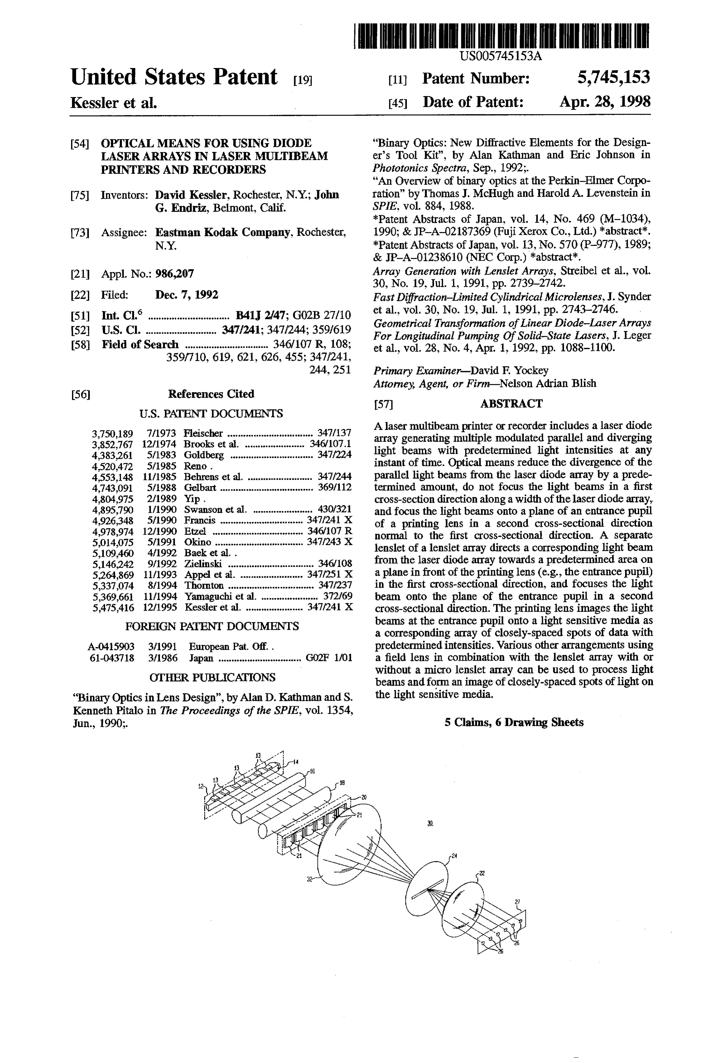
United States Patent 19 11 Patent Number: 5,745,153 Kessler et al. 45 Date of Patent: Apr. 28, 1998 54) OPTICAL MEANS FOR USING DIODE "Binary Optics: New Diffractive Elements for the Design LASER ARRAYS IN LASER MULTIBEAM er's Tool Kit", by Alan Kathman and Eric Johnson in PRINTERS AND RECORDERS Phototonics Spectra, Sep., 1992;.
"An Overview of binary optics at the Perkin-Elmer Corpo 75 Inventors: David Kessler, Rochester, N.Y.; John ration" by Thomas J. McHugh and Harold A. Levenstein in G. Endriz, Belmont, Calif. SPIE, vol. 884, 1988.
*Patent Abstracts of Japan, vol. 14, No. 469 (M-1034), 73) Assignee: Eastman Kodak Company, Rochester, 1990; & JP-A-02187369 (Fuji Xerox Co., Ltd.) *abstract. N.Y. *Patent Abstracts of Japan, vol. 13, No. 570 (P-977), 1989;
21 Appl. No.: 986,207 Array Generation with Lenslet Arrays, Streibel et al., vol.
22 Filed; Dec. 7, 1992 Fast Diffraction-Limited Cylindrical Microlenses, J. Synder (51 Int. Cl. ................ B41 2/47; G02B 27/10 et al., vol. 30, No. 19, Jul. 1, 1991, pp. 2743-2746. 52 U.S. Cl. .............. 347/241; 347/244; 359/619 Geometrical Transformation of Linear Diode-Laser Arrays For Longitudinal Pumping Of Solid-State Lasers, J. Leger 58 Field of Search ................................ 346/107 R, 108; et al., vol. 28, No. 4, Apr. 1, 1992, pp. 1088-1100.
Attorney, Agent, or Firm-Nelson Adrian Blish
3,750,189 7/1973 Fleischer ... ... 347/137 Alaser multibeam printer or recorder includes a laser diode 3,852,767 12/1974 Brooks et al. 34.6/107.1 array generating multiple modulated parallel and diverging 4,383.261 5/1983 Goldberg ............................... 347/224 light beams with predetermined light intensities at any 4,520,472 5/1985 Reno. instant of time. Optical means reduce the divergence of the 4,553,148 11/1985 Behrens et al. ......................... 347/244 parallel light beams from the laser diode array by a prede 4,743,091 5/1988 Gelbart .................................... 369/112 termined amount, do not focus the light beams in a first 4,804.975 2/1989 Yip . cross-section direction along a width of the laser diode array, 4,895,790 1/1990 Swanson et al. ....................... 430/.321 and focus the light beams onto a plane of an entrance pupil 4926,348 5/1990 Francis .......... ... 347/241 X of a printing lens in a second cross-sectional direction 4,978,974 12/1990 Etzel ................................... 346/07 R normal to the first cross-sectional direction. A separate 5,014,075 5/1991 Okino .................................. 347/243 X lenslet of a lenslet array directs a corresponding light beam 5,109,460 4/1992 Baek et al.. from the laser diode array towards a predetermined area on 5,146,242 9/1992 Zielinski ................................. 34.6/108 5,264869 11/1993 Appel et al. . ... 347/251 X a plane in front of the printing lens (e.g., the entrance pupil) 5,337,074 8/1994 Thornton ................................. 347/237 in the first cross-sectional direction, and focuses the light 5,369,661 11/1994 Yamaguchi et al. ...................... 372/69 beam onto the plane of the entrance pupil in a second 5,475,416 12/1995 Kessler et al. ...................... 347/241X cross-sectional direction. The printing lens images the light FOREIGN PATENT DOCUMENTS beams at the entrance pupil onto a light sensitive media as a corresponding array of closely-spaced spots of data with
A-0415903 3/1991 European Pat. Off.. predetermined intensities. Various other arrangements using 61-043718 3/1986 Japan ............................... GO2F 1/O1 a field lens in combination with the lenslet array with or
OTHER PUBLICATIONS
without a micro lenslet array can be used to process light beams and form an image of closely-spaced spots of light on
"Binary Optics in Lens Design”, by Alan D. Kathman and S. the light sensitive media. Kenneth Pitalo in The Proceedings of the SPIE, vol. 1354,
Jun., 1990;. 5 Claims, 6 Drawing Sheets
Page 2
Drawing sheet — no readable text.
Page 3
Drawing sheet — no readable text.
Page 4
Drawing sheet — no readable text.
Page 5
Drawing sheet — no readable text.
Page 6
Drawing sheet — no readable text.
Page 7
c. iA -- - - - - - - - - - as as a - - - - - - - - - - - or se - r is a ---------- s that
Page 8
OPTICAL MEANS FOR USING DODE The prior art arrangements do not provide a cost effective LASER ARRAYS IN LASER MULTIBEAM solution since the prior art arrangements use a number of PRINTERS AND RECORDERS individually packaged diode lasers in a closely packed array of diode lasers while other prior art arrangements do not
FIELD OF THE INVENTION provide closely packed laser light spots at the recording The present invention relates to techniques for efficiently medium. Therefore, it is desirable to provide cost effective using laser diode arrays in laser printer and recorders, and, methods and arrangements for using laser diode arrays in more particularly, to the use of lenslet arrays with laser diode laser printers and recorders. arrays in laser multibeam printers and recorders. O SUMMARY OF THE INVENTION BACKGROUND OF THE INVENTION The present invention is directed to providing cost effec In laser thermal printers, the optical power of lasers is tive method and arrangements for using laser diode arrays in used to affect a transfer of a dye or ink from a donor medium laser printers and recorders, and, more particularly, to the to a receiver member that form a recording medium. To 15 use of lenslet arrays with laser diode array for use in enhance the printing speed of laser thermal printers, high multibeam laser printers or recorders. power is needed. One technique for achieving high power in Viewed from a first aspect, the present invention is a laser thermal printer is to use a number of independently directed to a laser thermal printer comprising a plurality of modulated diode lasers. U.S. Pat. No. 5,109,460 (S. Baeket diode lasers, a printing lens, optical means, and a lenslet al.), issued on Apr. 28, 1992, discloses an optical fiber print 20 array. The plurality of diode lasers are formed into a laser head system in which a number of independently modulated diode array, each diode laser generating a separate modu diode lasers are used, where each diode laser is coupled to lated diverging light beam of predetermined intensity at any an optical fiber. The other end of each of the optical fibers instant of time and having a predetermined aperture. The is placed in a grooved mount such that the fiber ends form printing lens has an entrance pupil for imaging the light a line of closely packaged spots forming a monolithic optical 25 beams from the laser diode array at a plane of the entrance fiber head. This optical fiber head is then imaged onto a pupil onto a printing media as a corresponding array of thermal dye media by a lens to form an array of closely closely-spaced spots of predetermined intensities. The spots spaced laser light spots. of the array have a spacing therebetween which is less than U.S. Pat. No. 4,743,091 (D. Gelbart), issued on May 10, a spacing between the light beams generated by the laser 1988, discloses an optical data storage apparatus in which 30 diode array. The optical means reduces the aperture or numerous independently modulated diode lasers, each diode divergence of the light beams from the plurality of diode laser having a separate collimator lens, are arranged as a lasers by a predetermined amount. Still further, the optical closely packed two dimensional array. Alens system is used means continues the direction of the light beams onto the to image the array onto an optical recording medium which plane of the entrance pupil of the printing lens. The lenslet is moving relative to the image of the laser diode array in 35 array comprises a separate lenslet for directing each of the order to scan the recording medium. light beams in a first cross-sectional direction along a width Each of the arrangements disclosed in U.S. Pat. Nos. of the laser diode array towards a predetermined area on a 5,109,460 and 4,743,091 use individually packaged diode plane in front of the printing lens. Still further, the lenslet lasers in a closely packed array of diode lasers. The cost of array focuses each of the light beams in a second cross packaging many lasers in such an arrangement is high. Still sectional direction normal to the first cross-sectional direc further, variations in each of the laser channels due to tion onto the plane of the entrance pupil. differences between the lasers and/or the optical fibers In a first embodiment of the laser thermal printer of the results in variations between the light spot shapes or inten present invention, the lenslet array is disposed for receiving sities at the recording medium. It is preferable to use a the light beams from the optical means, and for directly monolithic array of diode lasers, namely, an array of diode 45 focusing and overlapping the light beams at a predetermined lasers formed on a same wafer in one package, and thus area of the entrance pupil of the printing lens. reduce packaging costs and laser-to-laser variations. In a second embodiment of the laser thermal printer of the U.S. Pat. No. 4,804.975 (K. Yip), issued on Feb. 14, 1989, present invention, the lenslet array substantially collimates discloses athermal dye transfer apparatus which includes an the light beams from the optical means in the first cross array of diode lasers that illuminate a dye carrying donor 50 sectional direction, and directs the substantially collimated medium. The donor medium absorbs heat from the laser light beams parallel to each other towards the plane of the light, and the dye is transferred by sublimation from the entrance pupil. A field lens receives the light beams from the donor medium to a receiver member to form pixels of an lenslet array, and directly focuses and overlaps the light image. Light from each of the diode lasers of the array is beams at the entrance pupil of the printing lens. modulated to have different pixel densities in order to print 55 In a third embodiment of the laser thermal printer of the the image on the receiver member. The light emitted from present invention, the plurality of diode lasers of the laser the diode lasers of the laser array is first collected by a diode array are formed into a plurality of subarrays of collimating lens and then focused by a focusinglens onto the closely-spaced diode lasers. Each subarray forms a separate donor medium. Each of the diode lasers corresponds to a multimode light source generating a separate multimode pixel in a line of the print image on the receiver member. light beam, and the diode lasers of a subarray are concur However, since the diode lasers of the array are not closely rently driven by a separate current source. Still further, the packed due to a design limitation of such arrays, a result is lenslet array focuses each of the light beams from the optical that the laser light spots at the recording medium are also not means in the first cross-sectional direction onto a separate closely packed. It is important to closely pack the laser light area of an exit plane disposed in front of a plane of an spots at the recording medium to minimize the field of the 65 entrance pupil of a printing lens. A field lens receives the printing lens, and to create artifact-free solid patches of a focused light beams from the exit plane, and to overlaps the transferred dye. light beams at the entrance pupil of the printing lens.
Page 9
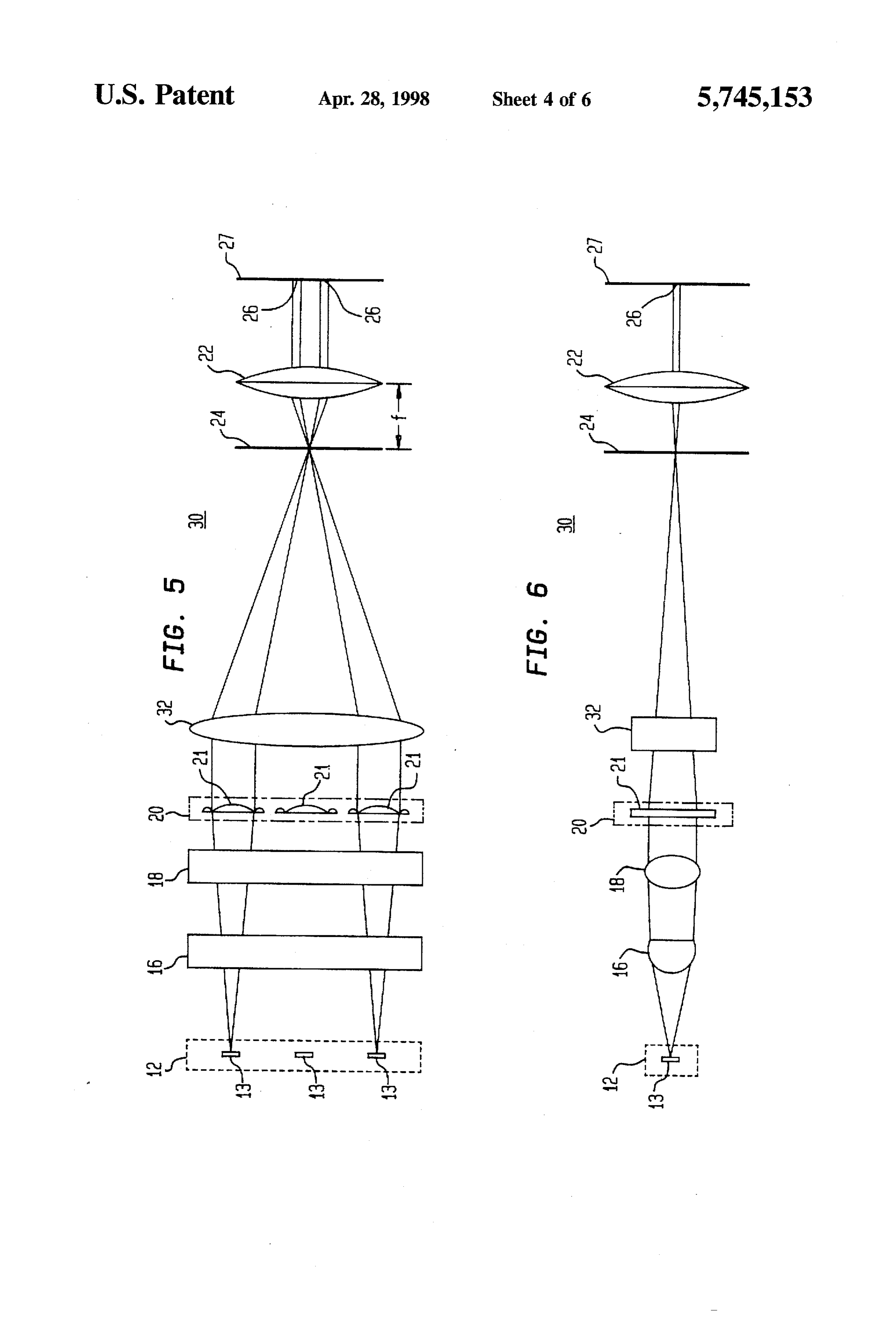
In a fourth embodiment of the laser thermal printer of the FIG. 5 is a cross-sectional view of a portion of the optical present invention, the plurality of diode lasers of the laser arrangement shown in FIG. 4 along a direction of a laser diode array are formed into a plurality of subarrays of diode diode array in a laser thermal printer;
lasers to form separate multimode light sources. Each sub FIG. 6 is a cross-sectional view of the optical arrangement array generates a separate multimode light beam, and the shown in FIG. 4 along a cross-array direction of a laser diode diode lasers of each subarray are concurrently driven by a array in a laser thermal printer;
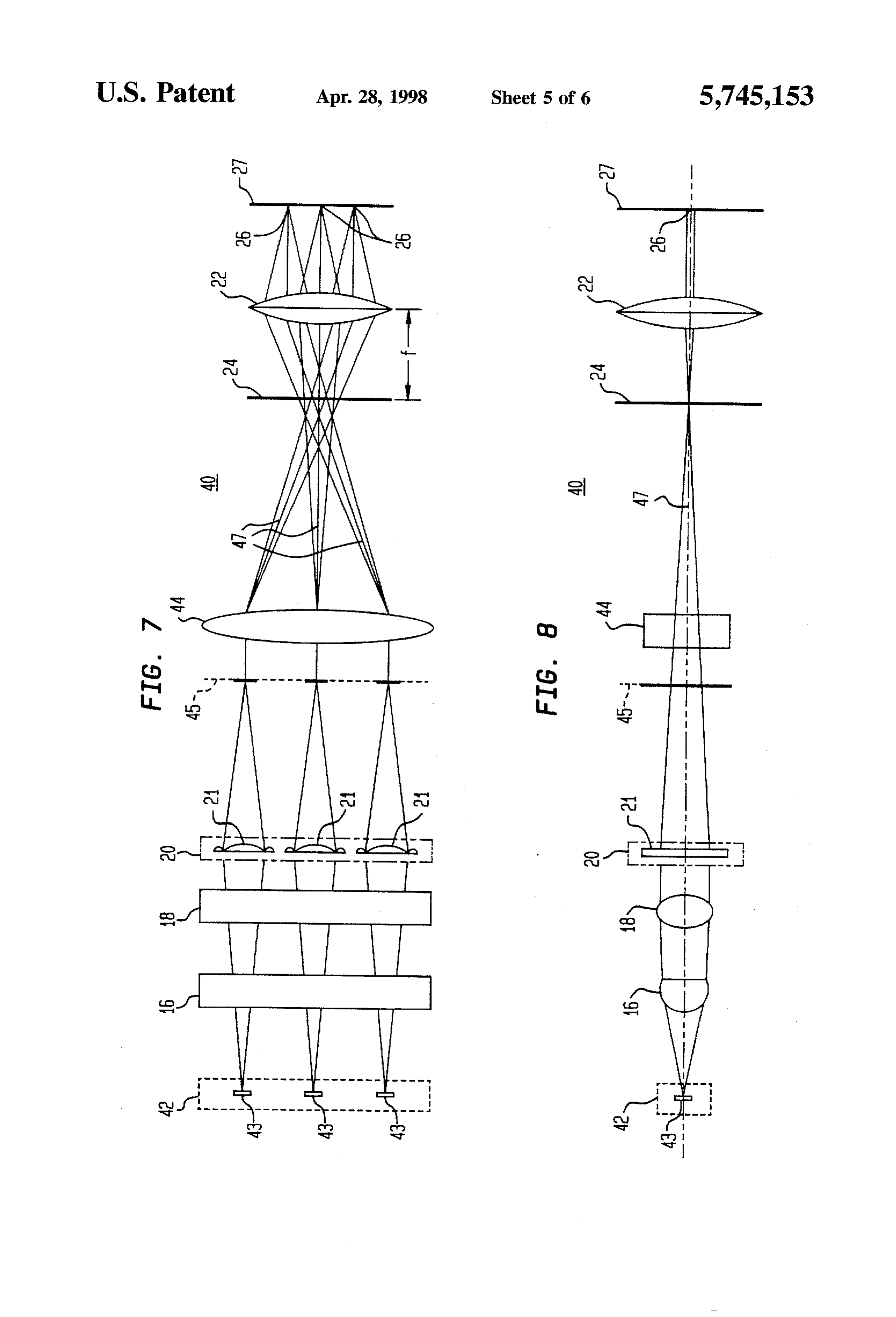
separate current source. The laser thermal printer also com FIG. 7 is a cross-sectional view of an optical arrangement prises a micro lenslet array, and a field lens. The micro along a direction of a laser diode array in a laser thermal lenslet array comprises a separate micro lenslet associated printer in accordance with a third embodiment of the present with each diode laser of the subarrays of diode lasers. Each 10 invention;
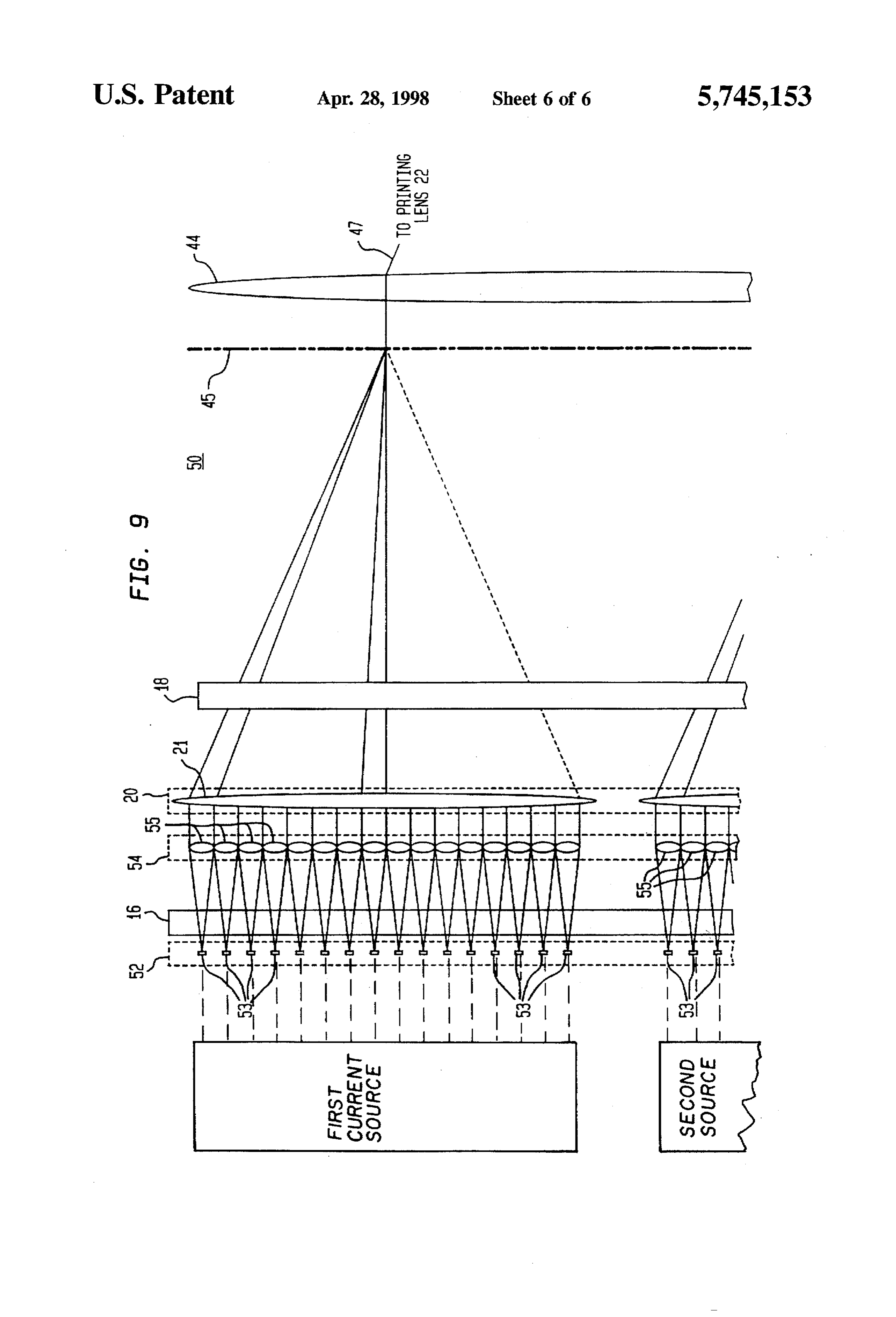
micro lenslet converts the diverging light beam from the FIG. 8 a cross-sectional view of the optical arrangement corresponding diode laser into a collimated light beam. Each shown in FIG.7 along a cross-array direction of a laser diode of the collimated light beams from a subarray Substantially array in a laser thermal printer; and touches a light beam from an adjacent micro lenslet asso FIG. 9 is a cross-sectional view of an optical arrangement ciated with a same subarray of diode lasers for forming a 5 along a direction of a laser diode array using subarrays of separate multimodelight beam. Each of the multimodelight multiple diode lasers in a laser thermal printer in accordance beams is directly received by a separate lenslet of the lenslet with a fourth embodiment of the present invention; array. The lenslet array focuses each of the multimode light The drawings are not necessarily to scale. beams along the first cross-sectional direction onto a sepa rate area of an exit plane disposed in front of the plane of the 20 DETALED DESCRIPTION entrance pupil of the printing lens. The field lens is disposed to receive the focused multimode light beams from the of In the descriptions hereinafter of the various embodiments the present invention, corresponding elements having the lenslet array, and to overlap the multimodelight beams at the same function in the various figures are given the same entrance pupil of the printing lens.
25 designation number. It is to be understood hereinafter that
Viewed from a second aspect, the present invention is directed to a method of generating an array of closely although the present invention is described with reference to spaced spots of predetermined intensities on a printing cable to opticalprinter, a laser thermal the disclosed arrangements are appli storage systems.
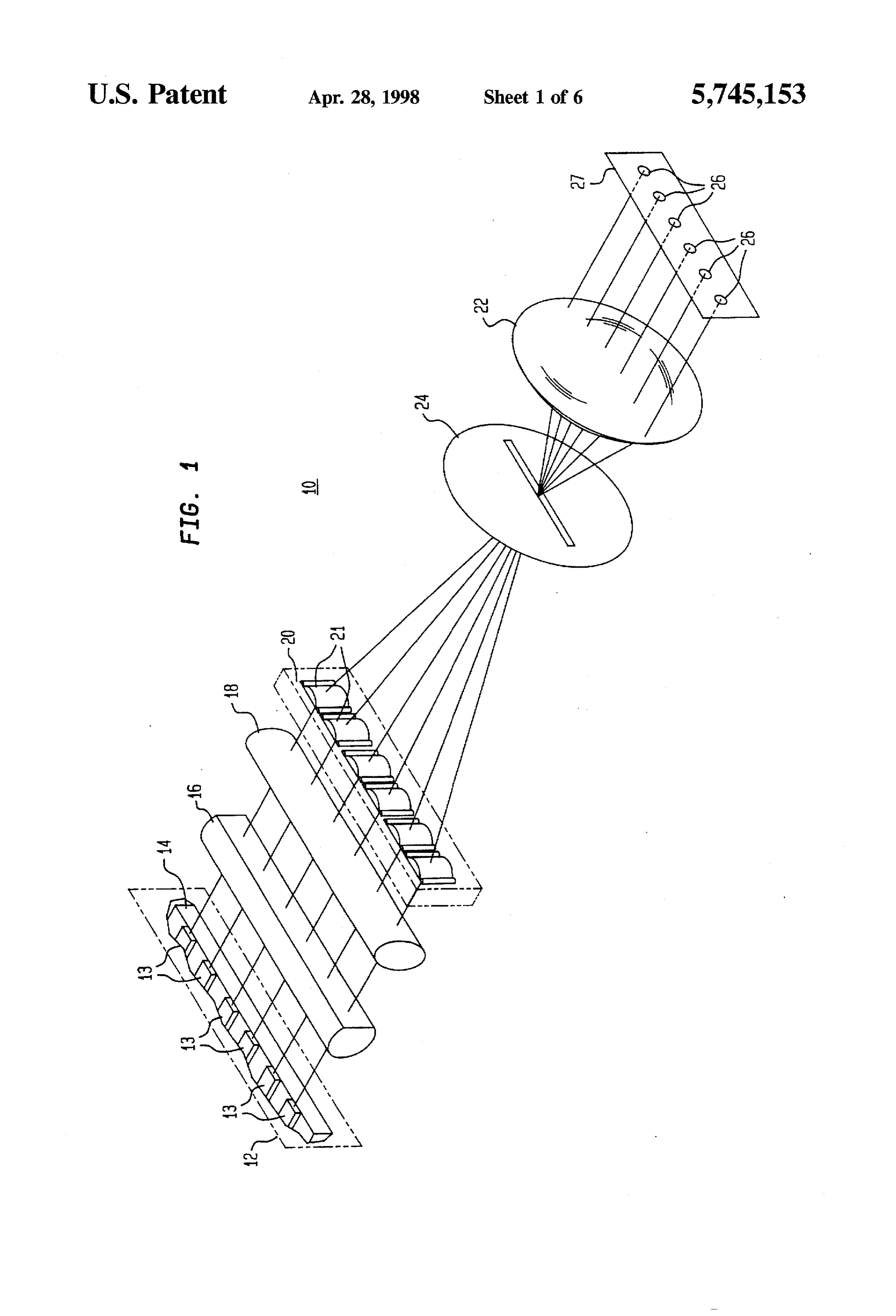
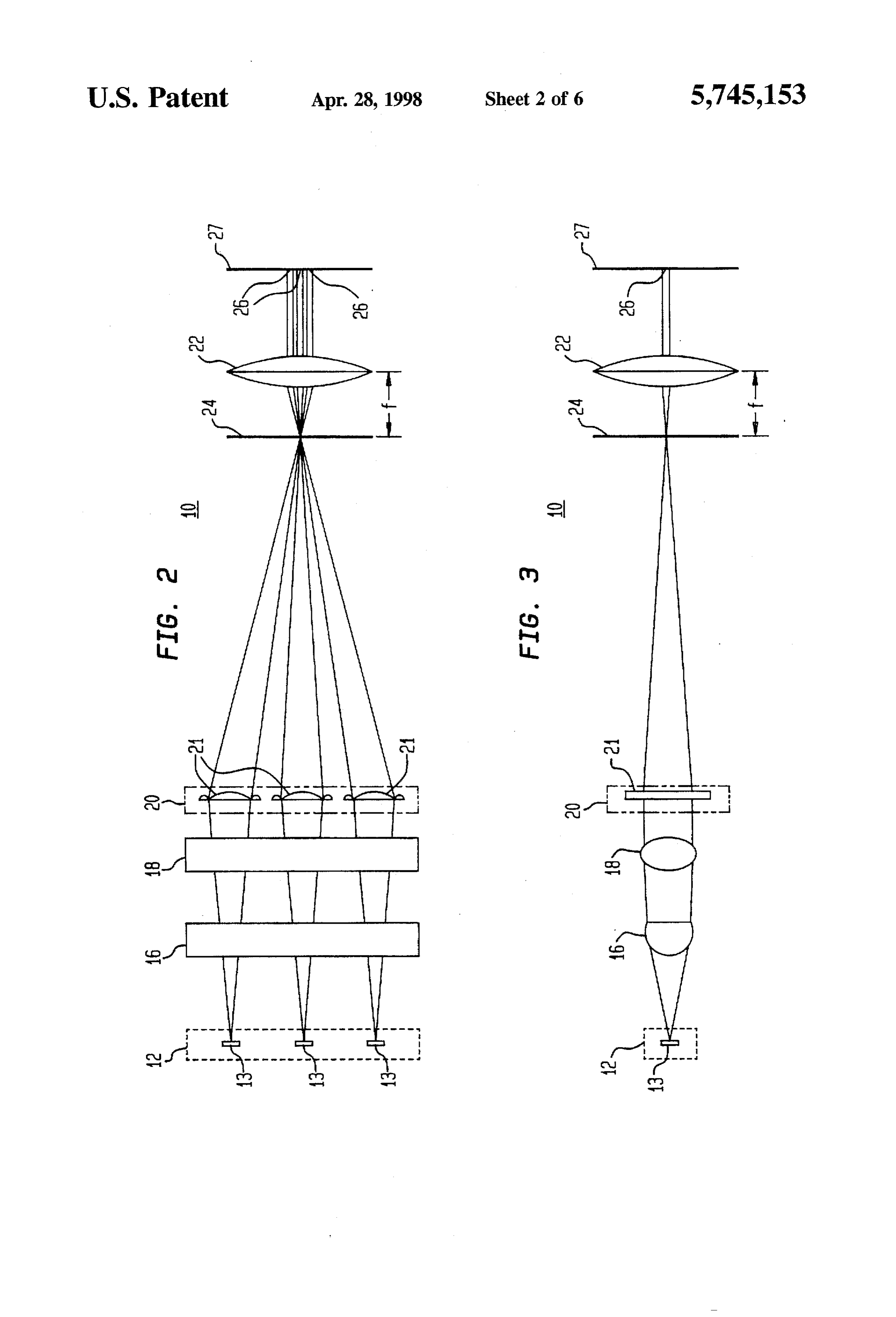
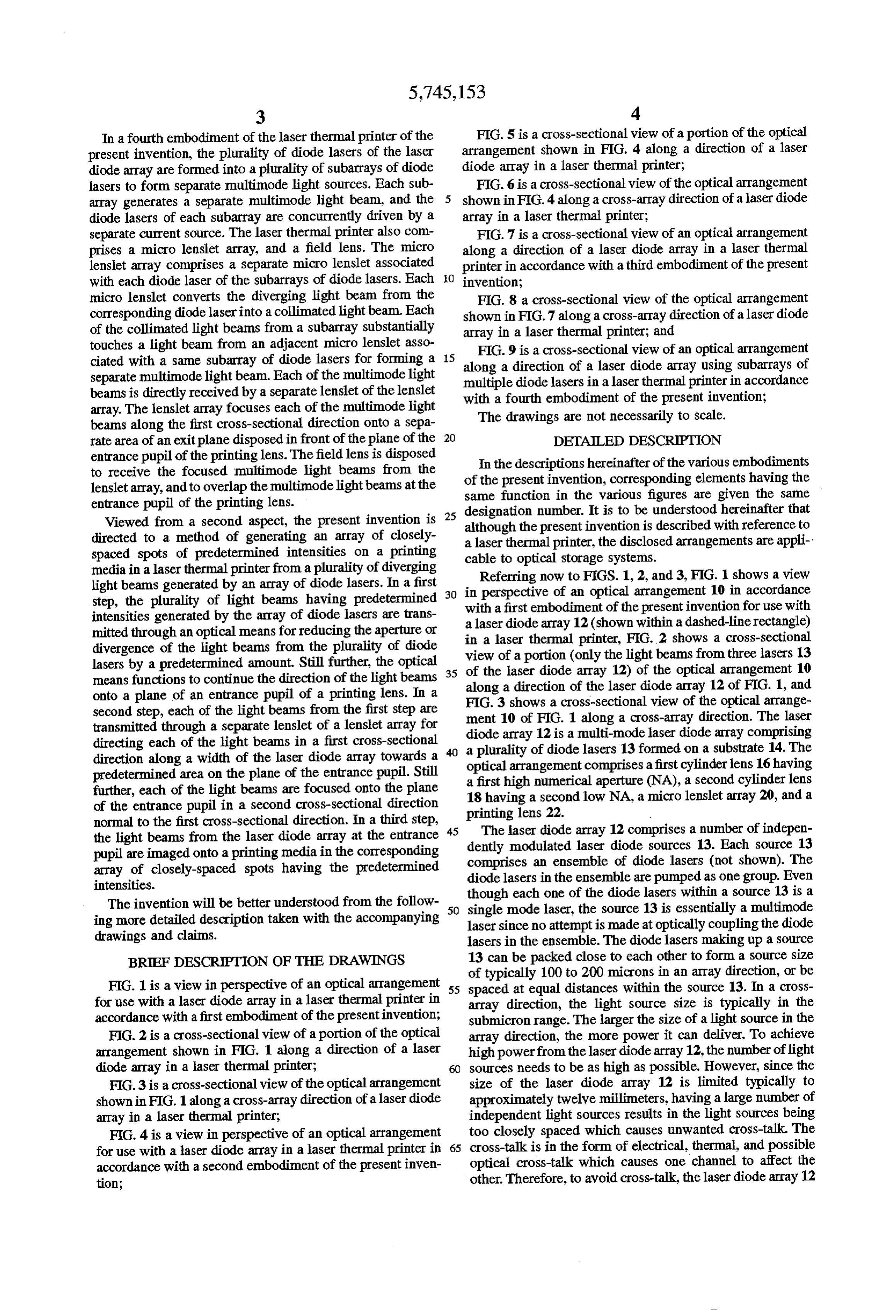
media in a laser thermal printer from a plurality of diverging light beams generated by an array of diode lasers. In a first 30 in Referring perspective now to FIGS. 1, 2, and 3, FIG. 1 shows a view of an optical arrangement 10 in accordance step, the plurality of light beams having predetermined with a first embodiment of the present invention for use with intensities generated by the array of diode lasers are trans a laser diode array 12 (shown within a dashed-line rectangle) mitted through an optical means for reducing the aperture or in a laser thermal printer, FIG.2 shows a cross-sectional divergence of the light beams from the plurality of diode view of a portion (only the light beams from three lasers 13 lasers by a predetermined amount. Still further, the optical 35 of the laser diode array 12) of the optical means functions to continue the direction of the light beams along a direction of the laser diode array 12arrangement 10 of FIG. 1, and onto a plane of an entrance pupil of a printing lens. In a FIG. 3 shows a cross-sectional view of the optical arrange second step, each of the light beams from the first step are transmitted through a separate lenslet of a lenslet array for ment 10 of FIG. 1 along a cross-array direction. The laser directing each of the light beams in a first cross-sectional diode a array 12 is a multi-mode laser diode array comprising plurality of diode lasers 13 formed on a substrate 14. The direction along a width of the laser diode array towards a optical arrangement predetermined area on the plane of the entrance pupil. Still a first high numericalcomprises a first cylinder lens 16 having further, each of the light beams are focused onto the plane 18 having a second low NA, a (NA),aperture micro a second cylinder lens lenslet array 20, and a of the entrance pupil in a second cross-sectional direction printing lens 22.
normal to the first cross-sectional direction. In a third step, The laser diode array 12 comprises a number of indepen the light beams from the laser diode array at the entrance 45 dently modulated laser diode sources 13. Each source 13 pupil are imaged onto a printing media in the corresponding comprises an ensemble of diode lasers (not shown). The array of closely-spaced spots having the predetermined intensities. diode lasers in the ensemble are pumped as one group. Even The invention will be better understood from the follow 50 single mode one though each of the diode lasers within a source 13 is a laser, the source 13 is essentially a multimode ing more detailed description taken with the accompanying laser since no attempt is made at optically coupling the diode drawings and claims. lasers in the ensemble. The diode lasers making up a source BRIEF DESCRIPTION OF THE DRAWINGS 13 can be packed close to each other to form a source size of typically 100 to 200 microns in an array direction, or be
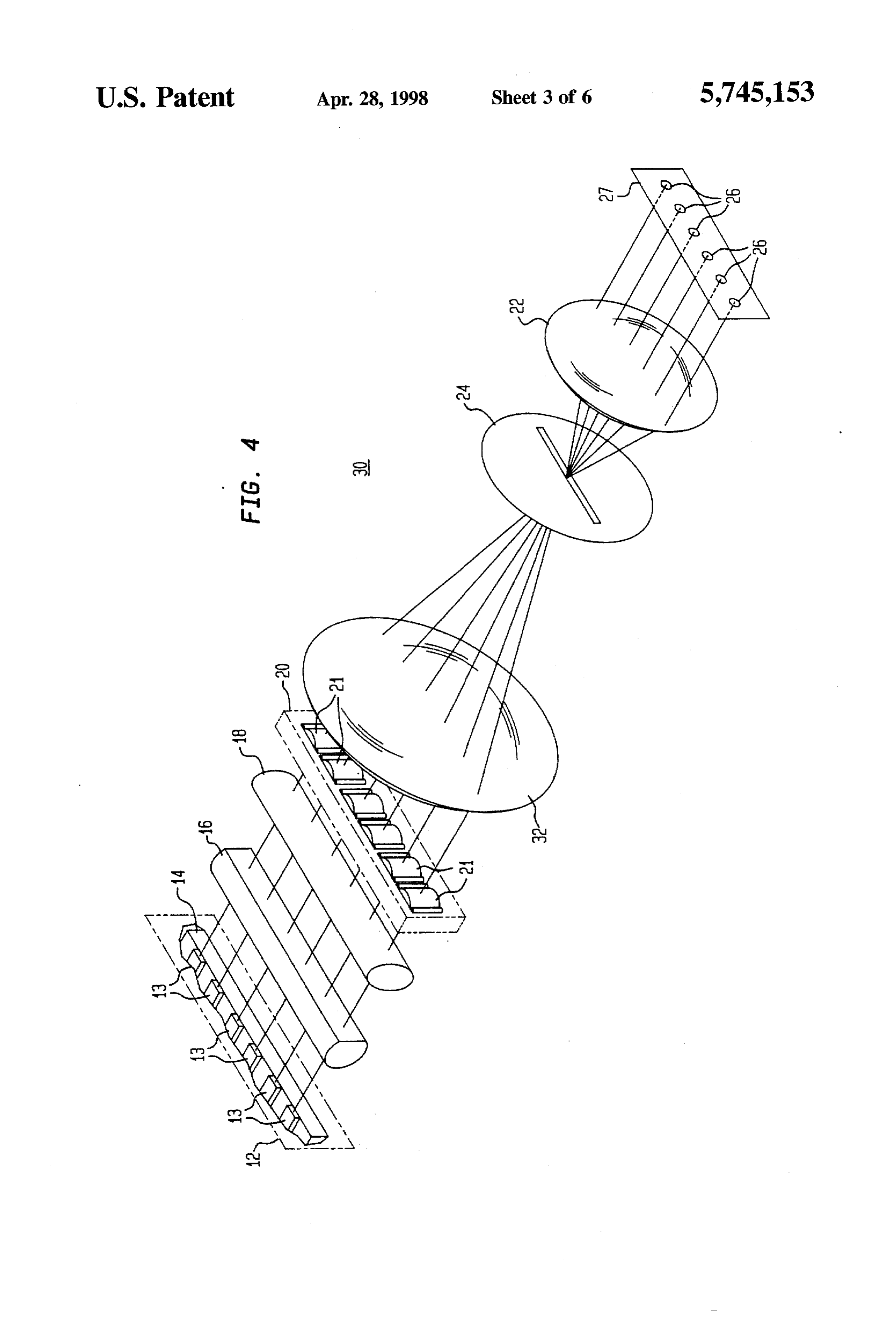
FIG. 1 is a view in perspective of an optical arrangement 55 spaced at equal distances within the source 13. In a cross for use with a laser diode array in a laser thermal printer in array direction, the light source size is typically in the accordance with a first embodiment of the presentinvention; submicron range. The larger the size of a light source in the FIG. 2 is a cross-sectional view of a portion of the optical array direction, the more power it can deliver. To achieve arrangement shown in FIG. 1 along a direction of a laser high power from the laser diode array 12, the number of light diode array in a laser thermal printer; sources needs to be as high as possible. However, since the FIG. 3 is a cross-sectional view of the optical arrangement size of the laser diode array 12 is limited typically to shown in FIG. 1 along a cross-array direction of a laser diode approximately twelve millimeters, having a large number of array in a laser thermal printer; independent light sources results in the light sources being FIG. 4 is a view in perspective of an optical arrangement too closely spaced which causes unwanted cross-talk. The for use with a laser diode array in a laser thermal printer in 65 cross-talk is in the form of electrical, thermal, and possible accordance with a second embodiment of the present inven optical cross-talk which causes one channel to affect the tion; other. Therefore, to avoid cross-talk, the laser diode array 12
Page 10
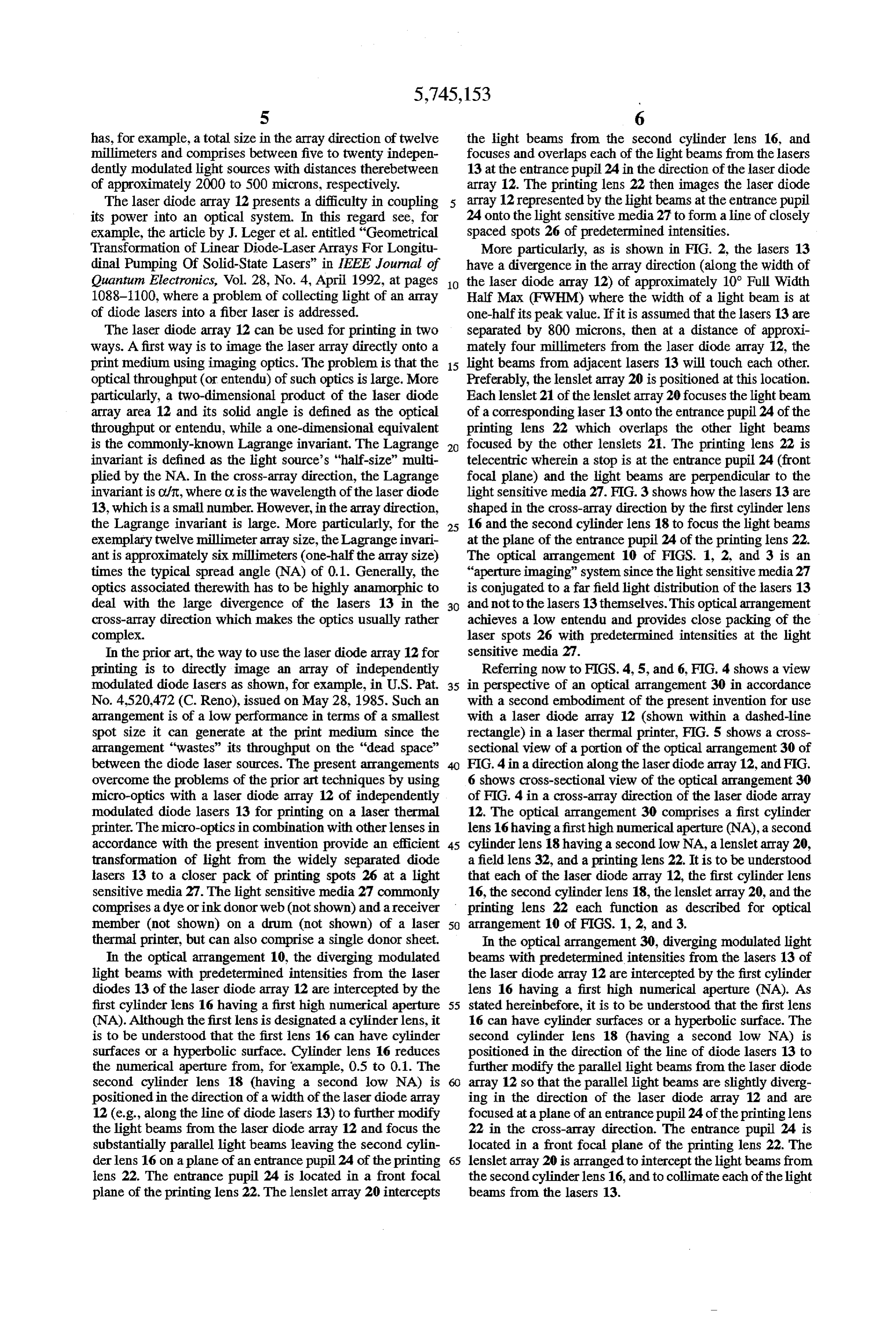
has, for example, a total size in the array direction of twelve the light beams from the second cylinder lens 16, and millimeters and comprises between five to twenty indepen focuses and overlaps each of the light beams from the lasers dently modulated light sources with distances therebetween 13 at the entrance pupil 24 in the direction of the laser diode of approximately 2000 to 500 microns, respectively. array 12. The printing lens 22 then images the laser diode The laser diode array 12 presents a difficulty in coupling 5 array 12 represented by the light beams at the entrance pupil its power into an optical system. In this regard see, for 24 onto the light sensitive media 27 to form a line of closely example, the article by J. Leger et al. entitled "Geometrical spaced spots 26 of predetermined intensities. Transformation of Linear Diode-Laser Arrays For Longitu More particularly, as is shown in FIG. 2, the lasers 13 dinal Pumping Of Solid-State Lasers” in IEEE Journal of have a divergence in the array direction (along the width of Quantum Electronics, Vol. 28, No. 4, April 1992, at pages to the laser diode array 12) of approximately 10° Full Width 1088-1100, where a problem of collecting light of an array Half Max (FWHM) where the width of a light beam is at of diode lasers into a fiber laser is addressed. one-half its peak value. If it is assumed that the lasers 13 are The laser diode array 12 can be used for printing in two separated by 800 microns, then at a distance of approxi ways. A first way is to image the laser array directly onto a mately four millimeters from the laser diode array 12, the print medium using imaging optics. The problem is that the 15 light beams from adjacent lasers 13 will touch each other. optical throughput (or entendu) of such optics is large. More Preferably, the lenslet array 20 is positioned at this location. particularly, a two-dimensional product of the laser diode Each lenslet 21 of the lenslet array 20 focuses the light beam array area 12 and its solid angle is defined as the optical of a corresponding laser 13 onto the entrance pupil 24 of the throughput or entendu, while a one-dimensional equivalent printing lens 22 which overlaps the other light beams is the commonly-known Lagrange invariant. The Lagrange 20 focused by the other lenslets 21. The printing lens 22 is invariant is defined as the light source's "half-size" multi telecentric wherein a stop is at the entrance pupil 24 (front plied by the NA. In the cross-array direction, the Lagrange focal plane) and the light beams are perpendicular to the invariantis Oft, where Ois the wavelength of the laser diode light sensitive media 27. FIG. 3 shows how the lasers 13 are 13, which is a small number. However, in the array direction, shaped in the cross-array direction by the first cylinder lens the Lagrange invariant is large. More particularly, for the 25 16 and the second cylinder lens 18 to focus the light beams exemplary twelve millimeter array size, the Lagrange invari at the plane of the entrance pupil 24 of the printing lens 22. antis approximately six millimeters (one-half the array size) The optical arrangement 10 of FIGS. 1, 2, and 3 is an times the typical spread angle (NA) of 0.1. Generally, the "aperture imaging" system since the lightsensitive media 27 optics associated therewith has to be highly anamorphic to is conjugated to a far field light distribution of the lasers 13 deal with the large divergence of the lasers 13 in the 30 and not to the lasers 13themselves. This optical arrangement cross-array direction which makes the optics usually rather achieves a low entendu and provides close packing of the complex. laser spots 26 with predetermined intensities at the light In the prior art, the way to use the laser diode array 12 for sensitive media 27.
printing is to directly image an array of independently Referring now to FIGS. 4, 5, and 6, FIG. 4 shows a view modulated diode lasers as shown, for example, in U.S. Pat. 35 in perspective of an optical arrangement 30 in accordance No. 4520,472 (C. Reno), issued on May 28, 1985. Such an with a second embodiment of the present invention for use arrangement is of a low performance in terms of a smallest with a laser diode array 12 (shown within a dashed-line spot size it can generate at the print medium since the rectangle) in a laser thermal printer, FIG. 5 shows a cross arrangement "wastes' its throughput on the "dead space” sectional view of a portion of the optical arrangement 30 of between the diode laser sources. The present arrangements 40 FIG. 4 in a direction along the laser diode array 12, and FIG. overcome the problems of the prior art techniques by using 6 shows cross-sectional view of the optical arrangement 30 micro-optics with a laser diode array 12 of independently of FIG. 4 in a cross-array direction of the laser diode array modulated diode lasers 13 for printing on a laser thermal 12. The optical arrangement 30 comprises a first cylinder printer. The micro-optics in combination with other lenses in lens 16 having a first high numerical aperture (NA), a second accordance with the present invention provide an efficient 45 cylinder lens 18having a second low NA, a lenslet array 20, transformation of light from the widely separated diode a field lens 32, and a printing lens 22. It is to be understood lasers 13 to a closer pack of printing spots 26 at a light that each of the laser diode array 12, the first cylinder lens sensitive media 27. The light sensitive media 27 commonly 16, the second cylinder lens 18, the lenslet array 20, and the comprises a dye orink donor web (not shown) and a receiver printing lens 22 each function as described for optical member (not shown) on a drum (not shown) of a laser 50 arrangement 10 of FIGS. 1, 2, and 3.
thermal printer, but can also comprise a single donor sheet. In the optical arrangement 30, diverging modulated light In the optical arrangement 10, the diverging modulated beams with predetermined intensities from the lasers 13 of light beams with predetermined intensities from the laser the laser diode array 12 are intercepted by the first cylinder diodes 13 of the laser diode array 12 are intercepted by the lens 16 having a first high numerical aperture (NA). As first cylinder lens 16 having a first high numerical aperture 55 stated hereinbefore, it is to be understood that the first lens (NA). Although the first lens is designated a cylinder lens, it 16 can have cylinder surfaces or a hyperbolic surface. The is to be understood that the first lens 16 can have cylinder second cylinder lens 18 (having a second low NA) is surfaces or a hyperbolic surface. Cylinder lens 16 reduces positioned in the direction of the line of diode lasers 13 to the numerical aperture from, for example, 0.5 to 0.1. The further modify the parallel light beams from the laser diode second cylinder lens 18 (having a second low NA) is 60 array 12 so that the parallel light beams are slightly diverg positioned in the direction of a width of the laser diode array ing in the direction of the laser diode array 12 and are 12 (e.g., along the line of diode lasers 13) to further modify focused at a plane of an entrance pupil 24 of the printing lens the light beams from the laser diode array 12 and focus the 22 in the cross-array direction. The entrance pupil 24 is substantially parallel light beams leaving the second cylin located in a front focal plane of the printing lens 22. The derlens 16 on a plane of an entrance pupil 24 of the printing 65 lenslet array20 is arranged to intercept the light beams from lens 22. The entrance pupil 24 is located in a front focal the second cylinder lens 16, and to collimate each of the light plane of the printing lens 22. The lenslet array 20 intercepts beams from the lasers 13.
Page 11
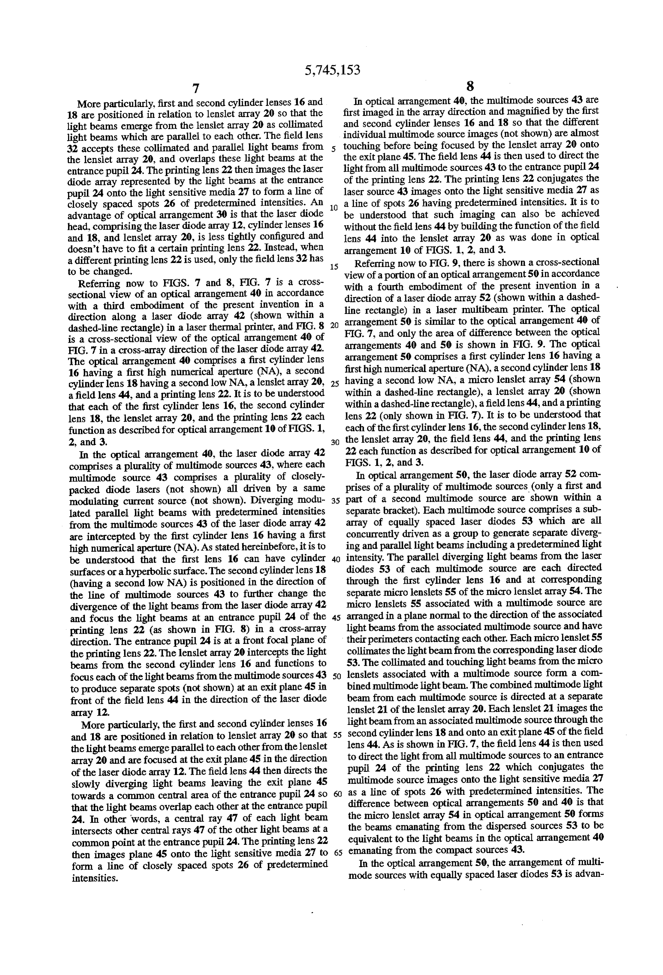
More particularly, first and second cylinder lenses 16 and In optical arrangement 40, the multimode sources 43 are 18 are positioned in relation to lenslet array 20 so that the first imaged in the array direction and magnified by the first light beams emerge from the lenslet array 20 as collimated and second cylinder lenses 16 and 18 so that the different light beams which are parallel to each other. The field lens individual multimode source images (not shown) are almost 32 accepts these collimated and parallel light beams from 5 touching before being focused by the lenslet array 20 onto the lenslet array 20, and overlaps these light beams at the the exit plane 45. The field lens 44 is then used to direct the entrance pupil 24. The printing lens 22 then images the laser light from all multimode sources 43 to the entrance pupil 24 diode array represented by the light beams at the entrance of the printing lens 22. The printing lens 22 conjugates the pupil 24 onto the light sensitive media 27 to form a line of laser source 43 images onto the light sensitive media 27 as closely spaced spots 26 of predetermined intensities. An 10 a line of spots 26 having predetermined intensities. It is to advantage of optical arrangement 30 is that the laser diode be understood that such imaging can also be achieved head, comprising the laser diode array 12, cylinder lenses 16 without the field lens 44 by building the function of the field and 18, and lenslet array 20, is less tightly configured and lens 44 into the lenslet array 20 as was done in optical doesn't have to fit a certain printing lens 22. Instead, when arrangement 10 of FIGS. 1, 2, and 3.
a different printing lens 22 is used, only the field lens 32 has 15 Referring now to FIG. 9, there is shown a cross-sectional to be changed. view of a portion of an optical arrangement 50 in accordance Referring now to FIGS. 7 and 8, FIG. 7 is a cross with a fourth embodiment of the present invention in a sectional view of an optical arrangement 40 in accordance with a third embodiment of the present invention in a direction of a laser diode array 52 (shown within a dashed direction along a laser diode array 42 (shown within a 20 arrangement 50 inis similar line rectangle) a laser multibeam printer. The optical to the optical arrangement 40 of dashed-line rectangle) in a laser thermal printer, and FIG. 8 FIG. 7, and only the area of difference between the optical is a cross-sectional view of the optical arrangement 40 of arrangements 40 and 50 is shown in FIG. 9. The optical FIG. 7 in a cross-array direction of the laser diode array 42.
The optical arrangement 40 comprises a first cylinder lens arrangement 50 comprises a first cylinder lens 16 having a 16 having a first high numerical aperture (NA), a second first high numerical aperture (NA), a second cylinder lens 18 cylinderlens 18 having a second low NA, a lenslet array 20, 25 having a second low NA, a micro lenslet array 54 (shown a field lens 44, and a printing lens 22. It is to be understood within a dashed-line rectangle), a lenslet array 20 (shown that each of the first cylinder lens 16, the second cylinder within a dashed-line rectangle), a field lens 44, and a printing lens 18, the lenslet array 20, and the printing lens 22 each lens 22 (only shown in FIG. 7). It is to be understood that function as described for optical arrangement 10 of FIGS. 1, each of the first cylinder lens 16, the second cylinderlens 18, 2, and 3. 30 the lenslet array 20, the field lens 44, and the printing lens In the optical arrangement 40, the laser diode array 42 22 each function as described for optical arrangement 10 of comprises a plurality of multimode sources 43, where each FIGS. 1, 2, and 3.
multimode source 43 comprises a plurality of closely In optical arrangement 50, the laser diode array 52 com packed diode lasers (not shown) all driven by a same prises of a plurality of multimode sources (only a first and modulating current source (not shown). Diverging modu 35 part of a second multimode source are shown within a lated parallel light beams with predetermined intensities separate bracket). Each multimode source comprises a sub from the multimode sources 43 of the laser diode array 42 array of equally spaced laser diodes 53 which are all are intercepted by the first cylinder lens 16 having a first concurrently driven as a group to generate separate diverg high numerical aperture (NA). As stated hereinbefore, it is to ing and parallel light beams including a predetermined light be understood that the first lens 16 can have cylinder intensity. The parallel diverging light beams from the laser surfaces or a hyperbolic surface. The second cylinder lens 18 diodes 53 of each multimode source are each directed (having a second low NA) is positioned in the direction of through the first cylinder lens 16 and at corresponding the line of multimode sources 43 to further change the separate micro lenslets 55 of the micro lenslet array54. The divergence of the light beams from the laser diode array 42 micro lenslets 55 associated with a multimode source are and focus the light beams at an entrance pupil 24 of the 45 arranged in a plane normal to the direction of the associated printing lens 22 (as shown in FIG. 8) in a cross-array light beams from the associated multimode source and have direction. The entrance pupil 24 is at a front focal plane of their perimeters contacting each other. Each micro lenslet 55 the printing lens 22. The lenslet array 20 intercepts the light collimates the light beam from the corresponding laser diode beams from the second cylinder lens 16 and functions to 53. The collimated and touching light beams from the micro focus each of the light beams from the multimode sources 43 50 lenslets associated with a multimode source form a com to produce separate spots (not shown) at an exit plane 45 in bined multimodelight beam. The combined multimodelight front of the field lens 44 in the direction of the laser diode beam from each multimode source is directed at a separate array 12. lenslet 21 of the lenslet array 20. Each lenslet 21 images the More particularly, the first and second cylinder lenses 16 light beam from an associated multimode source through the and 18 are positioned in relation to lenslet array 20 so that 55 second cylinder lens 18 and onto an exit plane 45 of the field the light beams emerge parallel to each other from the lenslet lens 44. As is shown in FIG.7, the field lens 44 is then used array 20 and are focused at the exit plane 45 in the direction to direct the light from all multimode sources to an entrance pupil 24 of the printing lens 22 which conjugates the of the laser diode array12. The field lens 44 then directs the multimode source images onto the light sensitive media 27 slowly diverging light beams leaving the exit plane 45 towards a common central area of the entrance pupil 24 so as a line of spots 26 with predetermined intensities. The that the light beams overlap each other at the entrance pupil difference between optical arrangements 50 and 40 is that 24. In other words, a central ray 47 of each light beam the micro lenslet array 54 in optical arrangement 50 forms intersects other central rays 47 of the other light beams at a the beams emanating from the dispersed sources 53 to be common point at the entrance pupil 24. The printing lens 22 equivalent to the light beams in the optical arrangement 40 then images plane 45 onto the light sensitive media 27 to 65 emanating from the compact sources 43. form a line of closely spaced spots 26 of predetermined In the optical arrangement 50, the arrangement of multi intensities. mode sources with equally spaced laser diodes 53 is advan
Page 12
tageous for heat management. By displacing the diode lasers 2. A laser multibeam printer comprising: 53 from each other, spaces are created between the laser a laser diode array comprised of a plurality of diode diodes 53 which increases the Lagrange invariant. As stated lasers, each of the diode lasers generating a separate hereinbefore, is it desirable that the Lagrange invariant be a one of a plurality of modulated diverging light beams Small as possible. In order to reduce this increased Lagrange of a predetermined intensity at any instant of time and invariant caused by the spaced-apartlaser diodes 53, a set of having predetermined emitting source size, each of the micro lenslets 55 (one for each laser diode 53) is used. diode lasers spaced from adjacent diode lasers by at It is to be appreciated and understood that the specific least the size of the emitting source size; embodiments of the invention described hereinbefore are a printing lens having an entrance pupil for imaging each merely illustrative of the general principles of the present O of the light beams from the laser diode array received invention. Various modifications may be made by those of at the entrance pupil onto a light sensitive media as a ordinary skill in the art which are consistent with the corresponding compact array of spots of predetermined principles set forth. For example, in the optical arrangement intensities with a spacing between the spots less than 50 of FIG. 9, the function of the micro lenslets 53 can be the size of the spot;
combined in the lenslet array 20 to form one component. 15 a first cylinder lens having a first numerical aperture for Still further, a single mode diode laser array can be used with collecting each of the diverging light beams from the all of the optical arrangements 10, 20, 30, 40, and 50. laser diode array, and for reducing the aperture or Furthermore, in the optical arrangements 10, 20, 30, 40, and divergence of each of the beams from the plurality of 50, the lenslet arrays 20 and the micro lenslet subarrays 54 diode lasers by a predetermined amount; are preferably optic binary lenslet arrays which are diffrac 20 a second cylinderlens having a second numerical aperture tive devices. However, it is to be understood that the lenslet which is less than the first numerical aperture for arrays 20 and the micro lenslet array 54 can be refractive collecting each of the light beams from the first cylin lenslet arrays and subarrays. An advantage of using the der lens, for further shaping each of the light beams, binary lenslet arrays 20 and subarrays 54 is that they are and for continuing the direction of each of the light produced using the same microlithographic methods used 25 beams onto a plane of the entrance pupil of the printing for making lasers. Therefore, masks can be produced to lens;
manufacture the binary elements in exactly the right dimen a lenslet array comprising a separate lenslet for each of the sions to fit the lasers, etc. Additionally, it is to be understood light beams for directing each of the light beams in a that the term "light” used hereinbefore is broadly used to refer to visible and infrared electromagnetic radiation. first cross-sectional direction along a width of the laser What is claimed is: diode array towards a predetermined area on a plane in 1. A laser multibeam printer comprising: front of the printing lens, and for focusing each of the a monolithic laser diode array comprised of a plurality of light beams in a second cross-sectional direction nor mal to the first cross-sectional direction onto the diode lasers, each of the diode lasers generating a 35 entrance pupil wherein:
separate one of a plurality of modulated diverging light the lenslet array substantially collimates each of the beams having a predetermined intensity at any instant light beams from the second cylinder lens in the first of time and having predetermined emitting source size, cross-sectional direction, and directs each of the each of the diode lasers spaced from adjacent diode substantially collimated light beams parallel to each lasers by at least the size of the emitting source size; other towards the plane of the entrance pupil; and a printing lens having an entrance pupil for imaging each a field lens which receives each of the substantially of the light beams from the laser diode array at a plane collimated light beams from the lenslet array and of the entrance pupil onto a light sensitive media as a focus and overlap each of the light beams at the corresponding compact array of spots of predetermined entrance pupil of the printing lens. intensities with a spacing between the spots less than 45 3. Amethod of generating an array of closely-spaced spots the size of the spot; of predetermined intensities on a light sensitive media in a optical means for reducing the aperture or divergence of laser multibeam printer from a plurality of diverging light each of the light beams from the plurality of diode beams of predetermined intensities generated by a mono lasers by a predetermined amount, and for directing lithic array of laser diodes, said printer including a printing each of the light beams onto the plane of the entrance 50 lens having an entrance pupil, the method comprising the pupil of the printing lens; steps of:
a lenslet array comprising a separate lenslet associated (a) transmitting the plurality of light beams generated by with each of the light beams, wherein each said lenslet the array of laser diodes through an optical means for directs said associated one of the light beams in a first reducing the aperture or divergence of the light beams cross-sectional direction along a width of the laser 55 from the plurality of diode lasers by a predetermined diode array towards a predetermined area on a plane in amount in a first cross-sectional direction; front of the printing lens, for focusing each of said light (b) transmitting the light beams from step (a) through a beams in a second cross-sectional direction onto the separate lenslet of a lenslet array for directing each of plane of the entrance pupil, wherein: the light beams in a second cross-sectional direction, the lenslet array substantially collimates each of the normal to the first cross-sectional direction, along a light beams from the optical means in the first width of the laser diode array towards a predetermined cross-sectional direction, and directs each of the area on a plane of the entrance pupil; substantially collimated light beams parallel to each (b1) receiving each of the light beams from the optical other towards the plane of the entrance pupil; and means at the lenslet array; and a field lens which receives each of the light beams from 65 (b2) arranging the lenslet array for directly focusing the lenslet array and focuses and overlaps each of the and overlapping each of the light beams at the light beams at the entrance pupil of the printing lens. entrance pupil of the printing lens;
Page 13
(c) focusing each of the light beams from the lenslet array (d) imaging each of the light beams from the entrance onto the plane of the entrance pupil; and pupil onto a light sensitive media in a corresponding (d) imaging each of the light beams from the entrance array of closely-spaced spots. 5. A method of generating an array of closely-spaced spots pupil onto a light sensitive media in a corresponding 5 of predetermined array of closely-spaced spots. intensities on a light sensitive media in a 4. Amethod of generating an array of closely-spaced spots laser multibeam printer from a plurality of diverging light of predetermined intensities on a light sensitive media in a beams of predetermined intensities generated by a mono laser multibeam printer from a plurality of diverging light lithichaving array of laser diodes, said printer including a printing beams of predetermined intensities generated by a mono 10 lens steps of:
an entrance pupil, the method comprising the lithic array of laser diodes, said printer including a printing lens having an entrance pupil, the method comprising the (a) transmitting each of the plurality of light beams steps of: intensities generated by a monolithic array of laser generated by the array of laser diodes through an diodes, said printer including a printing lens having an optical means for reducing the aperture or divergence entrance pupil, the method comprising the steps of: of each of the light beams from the plurality of diode (a) transmitting each of the plurality of light beams 15 lasers by a predetermined amount in a first cross generated by the array of laser diodes through an sectional direction;
optical means for reducing the aperture or divergence (a1) forming the plurality of diode lasers of the laser of each of the light beams from the plurality of diode diode array into a plurality of subarrays of closely lasers by a predetermined amount in a first cross spaced diode lasers for forming separate multimode sectional direction; light sources generating separate multimode light (a1) forming the plurality of diode lasers of the laser beams, each of the subarrays being driven by a diode array into a plurality of subarrays of closely separate current source, and each of the diode lasers spaced diode lasers for forming separate multimode of a subarray being driven concurrently; light sources generating separate multimode light 25 (a2) transmitting each of the plurality of multimode beams, each of the subarrays being driven by a light beams generated by the Subarrays of laser separate current source, and each of the diode lasers diodes through a first cylinder lens having a numeri of a subarray being driven concurrently; cal aperture for collecting the diverging light beams (a2) transmitting each of the plurality of multimode from the laser diode array, and for reducing the light beams generated by the subarrays of laser 30 aperture of divergence of each of the light beams diodes through a first cylinder lens having a numeri from the plurality of diode lasers by a predetermined cal aperture for collecting the diverging light beams amount; and from the laser diode array, and for reducing the (a3) collecting each of the light beams from the first aperture of divergence of each of the light beams cylinder lens by a second cylinder lens having a from the plurality of diode lasers by a predetermined 35 second numerical aperture which is lass than the first amount; and numerical aperture for further shaping the light (a3) collecting each of the light beams from the first beams, and for continuing the direction of the light cylinder lens by a second cylinder lens having a beams onto a plane of the entrance pupil of the second numerical aperture which is less than the first printing lens;
numerical aperture for further shaping the light (b) transmitting each of the light beams from step (a) beams, and for continuing the direction of the light through a separate lenslet of a lenslet array for directing beams onto a plane of the entrance pupil of the each of the light beams in a second cross-sectional printing lens; direction, along a width of the laser diode array towards (b) transmitting each of the light beams from step (a) a predetermined area on the plane of the entrance pupil; through a separate lenslet of a lenslet array for directing 45 (c) focusing each of the light beams from the lenslet array each of the light beams in a second cross-sectional onto the plane of the entrance pupil; and direction, normal to the first cross-sectional direction, (d) imaging each of the light beams from the entrance along a width of the laser diode array towards a pupil onto a light sensitive media in a corresponding predetermined area on a plane of the entrance pupil; array of closely-spaced spots. (c) focusing each of the light beams from the lenslet array onto the plane of the entrance pupil; and
Provenance
- Collection
- Cited prior art
- Original PDF
- patentimages.storage.googleapis.com →
- Filed
- 1992-12-07
- Pages
- 13
- Method
- pdftotext (the PDF's own text layer) + pdftoppm 300dpi page scans
- Source
- Google Patents bibliographic record
- Granted
- 1998-04-28
- Inventors
- David Kessler; John G. Endriz; Eastman Kodak Co
- Transcribed from
- patentimages.storage.googleapis.com →