patent · US5614001
Hydrogen separator, hydrogen separating apparatus and method for manufacturing hydrogen separator
25 March 1997
Page 1 — bibliographic record
III USOO5614001A
III III
United States Patent (19) (11) . Patent Number: 5,614,001 Kosaka et al. 45) Date of Patent: Mar. 25, 1997
54 HYDROGEN SEPARATOR, HYDROGEN 5,358,553 10/1994 Najjar et al. ............................ 95/56 X SEPARATING APPARATUS AND METHOD 5,376,167 12/1994 Broutin et al........................... 96/10 X FOR MANUFACTURING HYDROGEN FOREIGN PATENT DOCUMENTS
SEPARATOR
45-0.14404 5/1970 Japan ......................................... 95/56 75) Inventors: Shinichi Kosaka, Osamu Sakai, both 55-119420 9/1980 Japan ......................................... 95/55 of Nagoya, Tomonori Takahashi, g: Z36 R as a - a a - - - - - - - - - a a a - a a a 2. f+r Takao Soma, Nishikamo-gun,
all apan . . . . . . . . . . . . . . . . . . . . . . . . . . . . . . . . . . . . . . . . . 61-157327 7/1986 Japan ... 96/10 p 62-017001 1/1987 Japan. ... 96/4 (73) Assignee: NGK Insulators, Ltd., Nagoya, Japan of SA A., R m 95/56
21 Appl. No.: 445,027 64-4216A 1/1989 Japan.
22 Filed: May 19, 1995 3-026322 2/1991 Japan ......................................... 96/10 30 Foreign Application Priority Data 3-052630 3/1991 Japan ... . . 96.f4 May 23, 1994 (JP) Japan .................................... 6-108623 OTHER PUBLICATIONS
Jun. 22, 1994 (JP) Japan .................................... 6-140340 Shigeyuki Uemiya et al., “Hydrogen permeable palladium 6 -silver alloy membrane supported on porous ceramics', 5l Int. Cl. ........................... B01D 53/22; F.E.T.: Journal of Membrane Science, 56, (1991) 315-325. (52) U.S. Cl. ..................................... 96/10; 96/11; 55/524; Primary Examiner-Robert Spitzer 55/DIG. 5; 95/55 Attorney, Agent, or Firm-Ronald J. Kubovcik 58) Field of Search ................................. 95/55, 56; 96/4, 96/8, 10, 1:55/524, DIG. 5 57) ABSTRACT
A hydrogen separator has a porous substrate having a 56) References Cited through-hole, and a metal having a hydrogen separating
porous substrate to close pores on the inner surface of the 2,773,561 12/1956 Hunter ........................................ 95/56 through-hole. A method for manufacturing a hydrogen sepa 3.245,206 4/1966 Bonnel. ... ... 96/10 rator by a chemical plating process, includes providing a 3,368,329 2/1968 Eguchi et al. ... 96 porous substrate having a through-hole, and forcedly circu 3359 2 E. Jr. ...................................... 3. lating a plating solution containing a metal having a hydro 3,413,777 1 Langley et al. .. gen separating ability through the through-hole of the Sub 3,428,476 2/1969 Langley et al... ... 96.1 X o 3.437,357 4f1969 Rubin 96/8. X strate. The inner surface of the through-hole is covered with 4,468,235 8/1984 Hill. Iox the metal film having the hydrogen separating ability. 5,205,841 4/1993 Waiman ... ... 9.5/56 X 5,215,729 671993 Buxbaum ................................ 95/56 X 12 Claims, 4 Drawing Sheets
Page 2
Drawing sheet — no readable text.
Page 3
Drawing sheet — no readable text.
Page 4
Drawing sheet — no readable text.
Page 5
Drawing sheet — no readable text.
Page 6
HYDROGEN SEPARATOR, HYDROGEN method. For example, Japanese Patent Application Laid SEPARATING APPARATUS AND METHOD open No. 4216/1989 has disclosed a technique which com FOR MANUFACTURNG HYDROGEN prises subjecting a substrate of a porous ceramic to electro SEPARATOR less palladium plating, and then forming a plating layer of electrolytic palladium or a palladium-containing alloy
BACKGROUND OF THE INVENTION thereon.
Furthermore, in Japanese Patent Application Laid-open (i) Field of the Invention No. 164419/1989, it has been disclosed that a palladium thin The present invention relates to a hydrogen separator for film is formed on the surface of a heat-resistant porous separating a hydrogen gas only from a mixed gas containing O substrate and a silver thin film is further formed on the hydrogen, a hydrogen separating apparatus using this hydro palladium thin film by the chemical plating method, respec gen separator, and a method for manufacturing the hydrogen tively, followed by a heat treatment, to allow silver and Separator. palladium to interdiffuse, thereby forming a hydrogen sepa (ii) Description of the Related Art rating film comprised of an alloy of silver and palladium. A hydrogen gas has been used in large quantities as a 15 In the conventional hydrogen separators, however, the fundamental material gas in a petroleum chemistry, and shape of the porous substrates is tubular or planar, and So it is difficult to increase the area of the hydrogen separating much expectation is put on the hydrogen gas as a clean films in a certain volume so as to heighten a hydrogen energy source. The high-purity hydrogen gas can be separation efficiency (a volume efficiency) per unit volume. obtained by converting a natural gas, a naphtha or the like 20 For example, if it is intended to increase the volume as a material into a gas containing hydrogen by virtue of a efficiency by the use of the tubular hydrogen separators, the catalyst, and then separating the hydrogen gas from the respective tubular hydrogen separators must be thinned so hydrogen-containing gas. that the most possible hydrogen separators may be received The hydrogen gas can be separated by utilizing the in a certain volume. However, if the tubular hydrogen characteristics of the hydrogen gas that the hydrogen gas can 25 separators are thinned, the strength of these separators be dissolved in palladium or an alloy containing palladium. unavoidably deteriorates. In addition, it is difficult to manu Since the hydrogen gas alone can be dissolved in these facture a plurality of the tubes having the same size with a metals, the hydrogen gas can be selectively separated. good accuracy, and even the slight unevenness of the size of In the case that palladium or the alloy containing palla the tubes makes the integration of these tubes difficult dium is used as a hydrogen separator, it is usually formed 30 Sometimes.
into a thin film. However, when the palladium thin film is Moreover, in the conventional hydrogen separators, the singly used, its mechanical strength is poor, and thus in hydrogen separating films are often formed on the outer Japanese Patent Application Laid-open No. 273030/1987, a surfaces of the porous substrates. However, most of the porous substrate of a porous ceramic or the like is coated porous substrates are lower in thermal expansion coefficient with the palladium thin film to increase the mechanical 35 as compared with palladium or an alloy containing palla strength. dium, and for this reason, when the porous substrates are In general, a hydrogen permeation velocity in the palla used at a high temperature, the hydrogen separating films dium film or the palladium alloy film can be represented by with which the outer surfaces of the tubular porous Sub the formula (1) strates are coated tend to peel and crack, so that the material 40 gas might leak into a purified gas.
When the hydrogen separators are attached to flanges or the like to construct the hydrogen separating apparatus, or when this apparatus is used, vibration occurs, so that wherein mechanical shock or friction is applied to the outer surfaces Q is a hydrogen gas permeation velocity (Ncm/min), 45 of the hydrogen separators to damage the hydrogen sepa S is a film area (cm), rating films on occasion.
t is a film thickness (cm), In the case that a difference of temperature distribution P is a partial pressure of a hydrogen gas in a material gas occurs in the hydrogen separating apparatus in which a (kg/cm'abs), plurality of the tubular hydrogen separators are used, the 50 conduction of heat is not carried out between the hydrogen
P is a partial pressure of a hydrogen gas in a permeated separators, so that thermal expansion increases in part of the gas (kg/cm'abs), and hydrogen separators, with the result that high stress is Kis a hydrogen gas permeation velocity constant (Ncm/ generated at the bonding positions of the hydrogen separa min(kg/cm)'. tors and the flanges. In consequence, airtightness at the As understood from the above-mentioned relation, in 55 bonding positions is inconveniently impaired. order to increase the permeation velocity of the hydrogen gas, it is necessary to increase a difference between the SUMMARY OF THE INVENTION hydrogen gas partial pressure in the material gas and the Objects of the present invention are to provide a hydrogen hydrogen gas partial pressure in the permeated gas. There separator and a method for manufacturing the hydrogen fore, when a reformed gas containing methane, carbon 60 separator, capable of solving the above-mentioned prob dioxide and the like is used as the material gas, the material lems.
gas pressure is set to a high pressure of from several kg/cmabs to about 10 kg/cm'abs, and the permeated gas Other object of the present invention is to provide a pressure is set to a pressure of from negative pressure to hydrogen separating apparatus utilizing the above hydrogen several kg/cm'abs. 65 separator.
As a technique of coating the porous substrate with the In order to achieve the above objects, the present inven palladium thin film, there has been known a chemical plating tors have intensively investigated, and as a result, it has been
Page 7
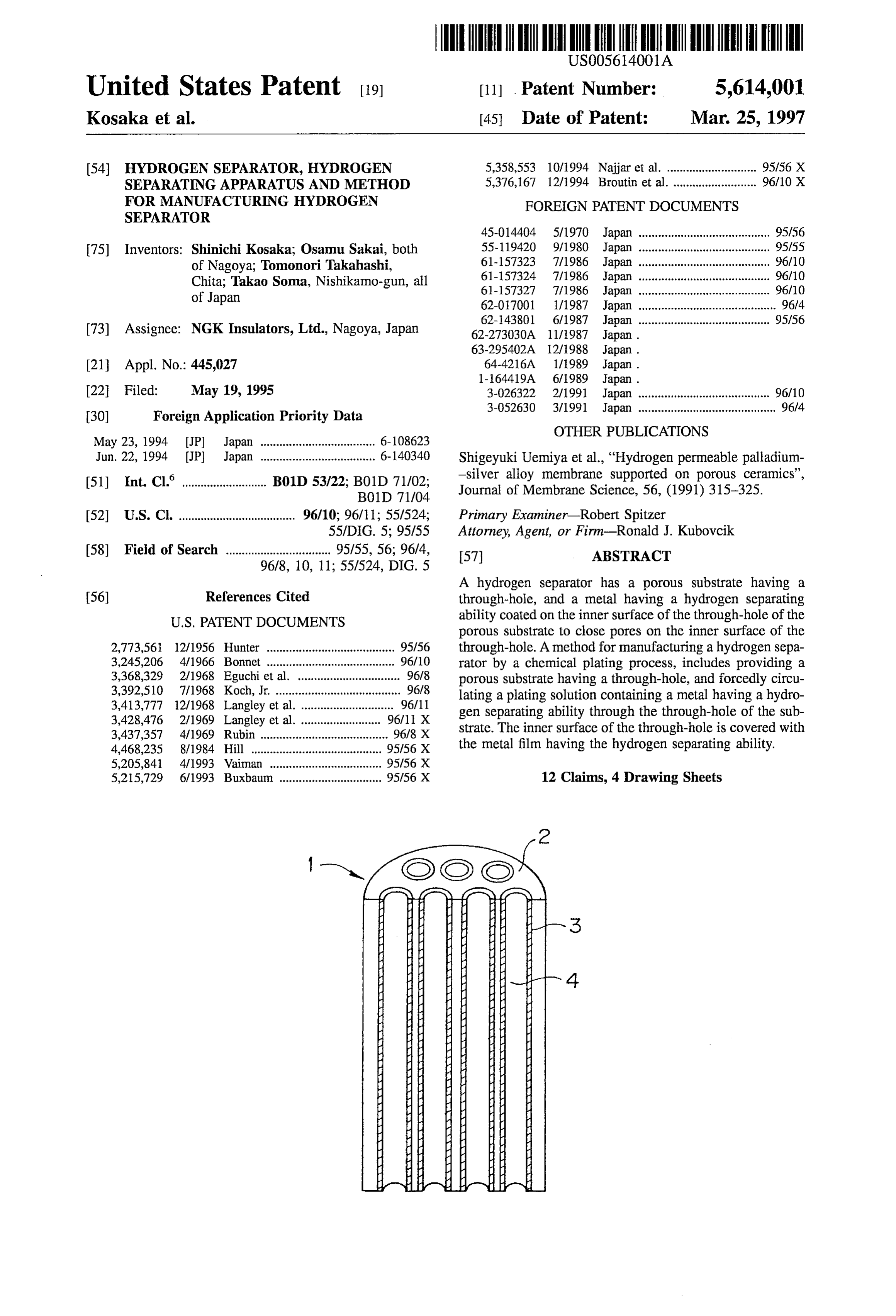
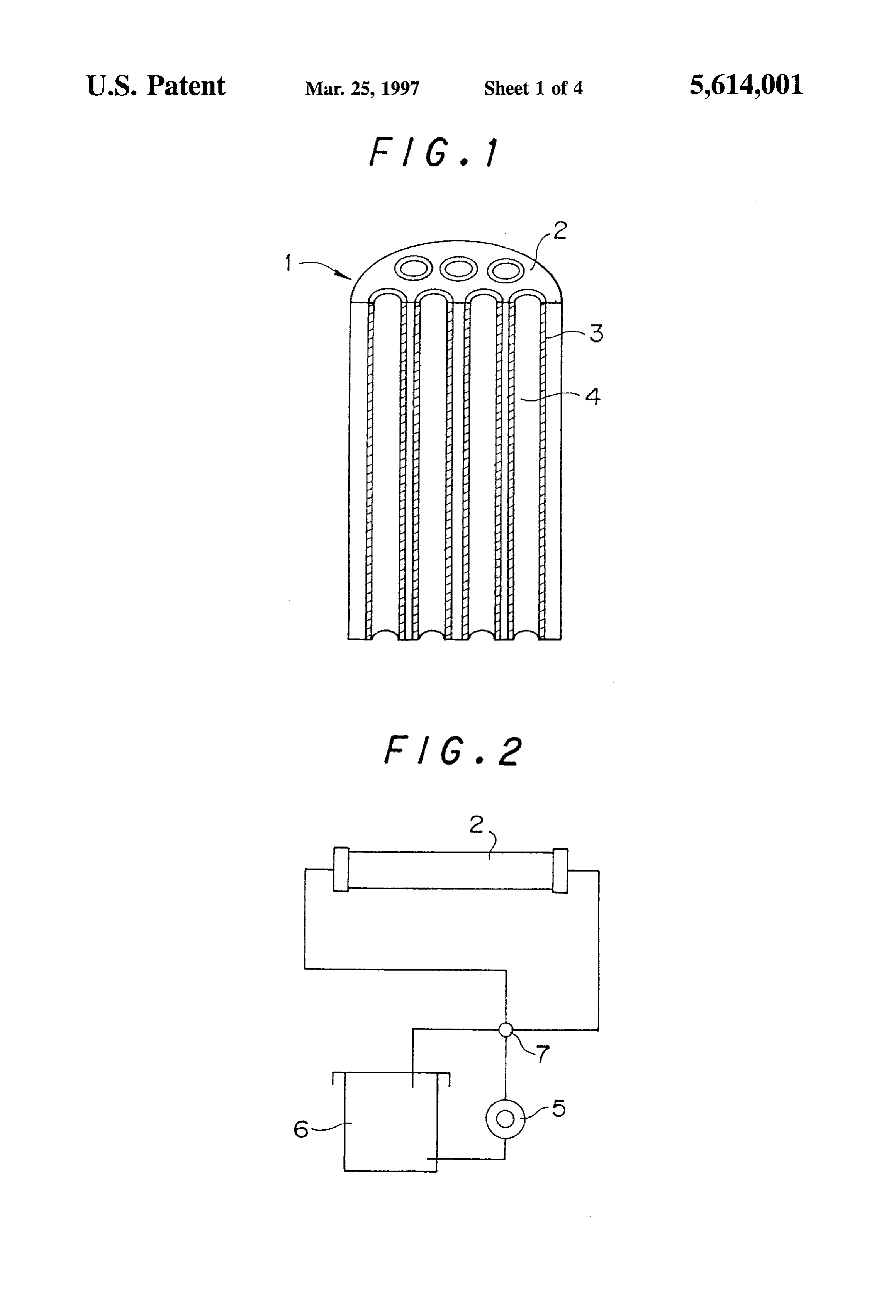
found that the above-mentioned problems can be solved by FIG. 6 is an illustrative view showing a further embodi the use of a porous substrate having through-holes. In ment of the hydrogen separator of the present invention. consequence, the present invention has been completed. FIG. 7 is an illustrative view of a gas purification process That is to say, according to one aspect of the present using the hydrogen separator of the present invention. invention, there can be provided a hydrogen separator com prising, a porous Substrate having a through-hole, and a metal having a hydrogen Separating ability, said metal DETAILED DESCRIPTION OF THE coating on the inner surface of the through hole of the porous INVENTION substrate to close pores on the inner surface of the through Next, the constitution of a hydrogen separator of the hole. O present invention will be described with reference to FIG. 1.
In the hydrogen separator of the present invention, it is A hydrogen Separator 1 is constituted of a porous sub preferable that the substrate has a plurality of the through strate 2 and hydrogen separating films 3 which cover the holes, and the metal having the hydrogen separating ability inner surfaces of through-holes 4.
is preferably palladium or an alloy containing palladium.
Furthermore, the diameter of the pores on the inner 15 tureThe porous substrate 2 preferably has a cylindrical struc having a plurality of the through-holes 4. However, the surface of the through-hole is preferably in the range of shape of the porous substrate 2 is not limited to the cylin 0.005 to 5 m. drical shape, and for example, a prismatic shape is also According to another aspect of the present invention, acceptable. In addition, the cylindrical or the prismatic there can be provided a method for manufacturing a hydro 20 structure may be curved along its axis. The shape of the gen Separator by a chemical plating process, comprising through-holes is usually a straight-line shape, but this is not providing a porous substrate having a through-hole, and restrictive. For example, the curved through-holes are also forcedly circulating a plating solution containing a metal acceptable.
having a hydrogen separating ability through the through The porous substrate 2 has many pores therein and on its hole of the substrate, whereby the inner surface of the 25 Surface, and these pores are connected to one another in a through-hole may be covered with the metal film having the three-dimensional state, whereby a gas can pass the porous hydrogen separating ability.
substrate 2 through these pores therein. The hydrogen sepa
In order to forcedly circulating the plating solution con rating films 3 cover inner surfaces of the through-holes 4 so taining the metal having the hydrogen separating ability as to fill and close the pores opened on the inner surfaces. through the through-hole of the substrate, a pump is pref 30 The hydrogen separating films 3 comprise a metal having erably used, and it is also preferable that the direction of the a hydrogen Separating ability. As such a metal, palladium or circulation can be switched.
an alloy containing palladium can be suitably used.
According to still another aspect of the present invention, When the material gas passes through the hydrogen there can be provided a hydrogen separating apparatus separating films 3, gas separation is carried out, and at this comprising, a container having an inlet for feeding a mate 35 time, the material gas is prevented from leaking into the side rial gas, a first outlet for discharging a hydrogen gas com of a purified gas, because the hydrogen separating films 3 ponent, and a second outlet for discharging an unpermeated cover the inner surfaces of the through-holes 4 so as to fill gas, and a hydrogen Separator Supported in an overhung State and close the pores opened on the inner surfaces of the in the container, the hydrogen separator comprising a porous through-holes 4. Therefore, for example, in the case of the substrate having a through-hole, and a metal having a 40 hydrogen separator of the present invention in which the hydrogen separating ability, said metal coating on the inner palladium alloy is used as the hydrogen separating films, a surface of the through-hole of the porous substrate to close hydrogen gas having a purity of 99% or more can be pores on the inner surface of the through-hole, wherein the obtained, and in general, the hydrogen gas having a purity of hydrogen gas component in the material gas fed through the 99.9% or more can be obtained.
inlet is allowed to permeate through the metal having a 45 hydrogen separating ability and then discharged through the For the porous substrate 2, there is required a material first outlet and the unpermeated gas is discharged through which reacts with neither the material gas nor the metal the second outlet. having the hydrogen separating ability and which withstands In the hydrogen separating apparatus, the hydrogen sepa high temperature and high pressure and which has excellent rator preferably has a plurality of the through-holes arranged 50 heat of the resistance and mechanical strength. Typical examples preferable material for the porous substrate 2 include in parallel and is suitably equipped with a cushion means for alumina, Silica, silica-alumina, mullite, cordierite, zirconia, absorbing the expansion of the hydrogen separator. carbon, porous glass, and a metal such as a stainless filter BRIEF DESCRIPTION OF THE DRAWINGS Subjected to a surface treatment.
FIG. 1 is a perspective view of a hydrogen separator of the 55 Of the pores of the porous substrate 2, the pores present present invention which is partially cut off. on the inner surfaces of the through-holes 4 are controlled to preferably
FIG. 2 is an illustrative view showing one embodiment of 0.01 to 1 um. have a diameter of 0.005 to 5 um, more preferably a technique of covering the inner surfaces of the through holes of a porous substrate with a metal. If the pore diameter is less than 0.005um, resistance to the 60 passage of the gas increases inconveniently. On the other
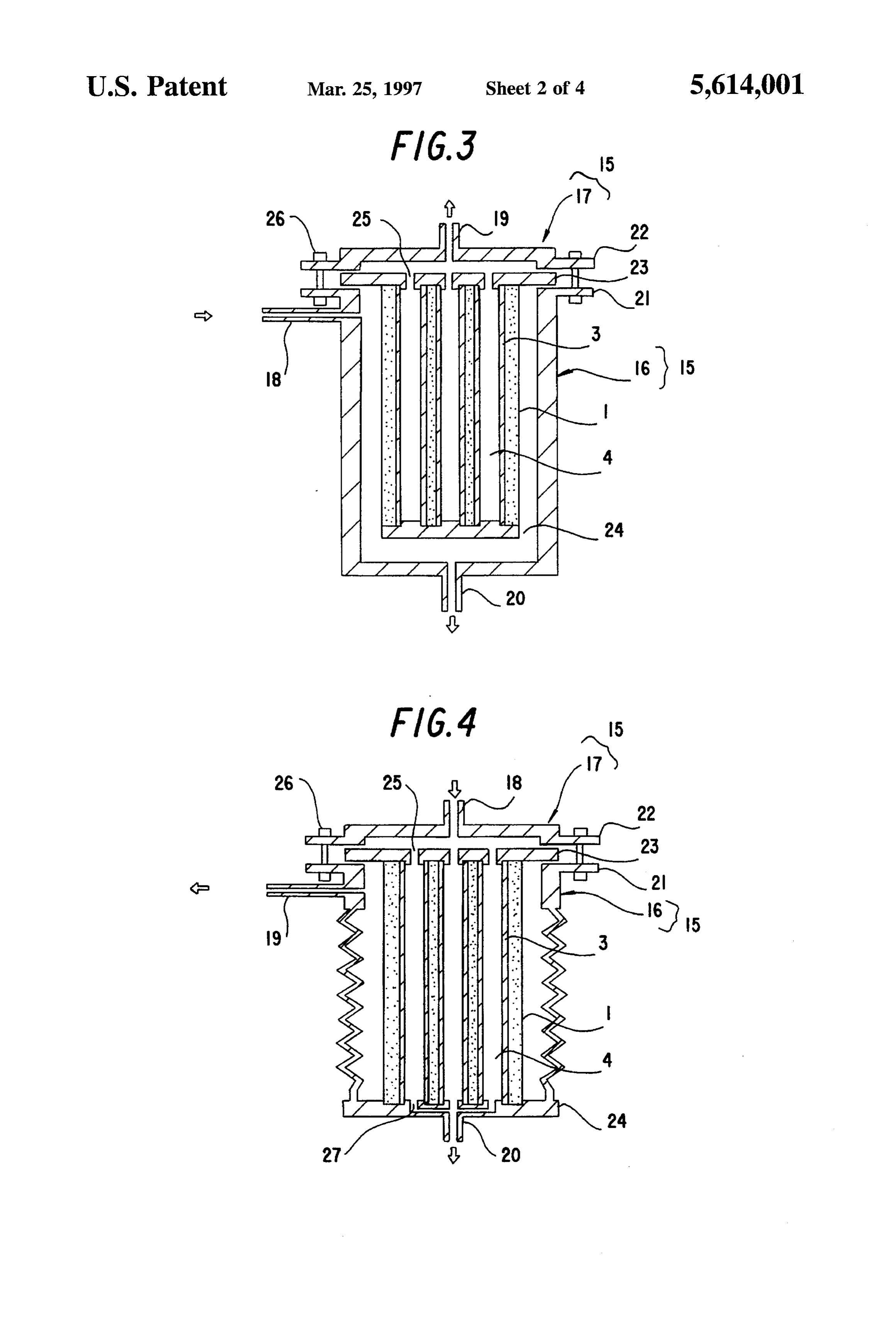
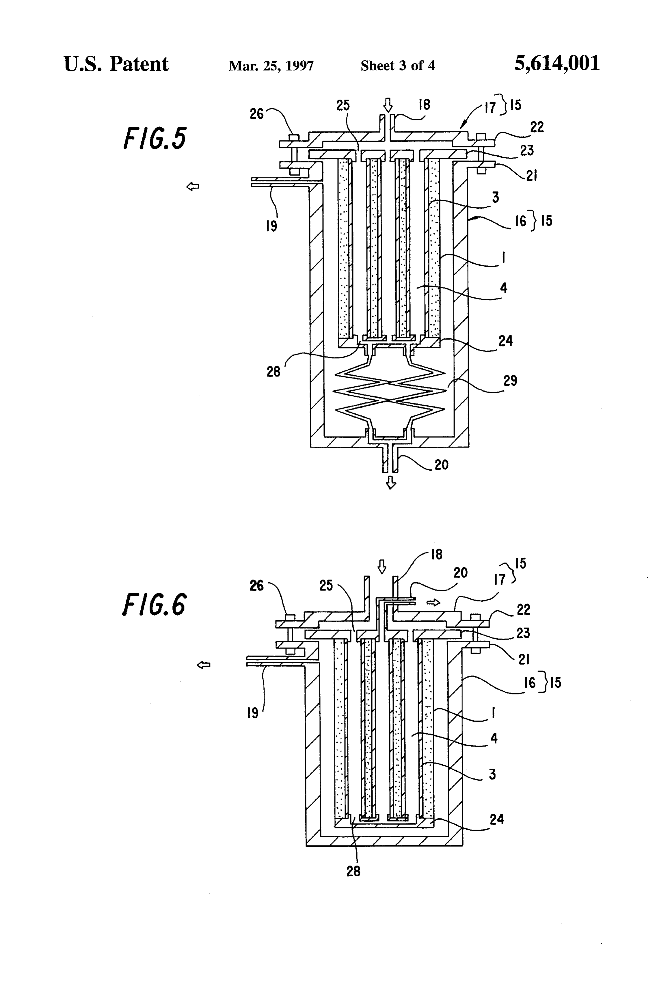
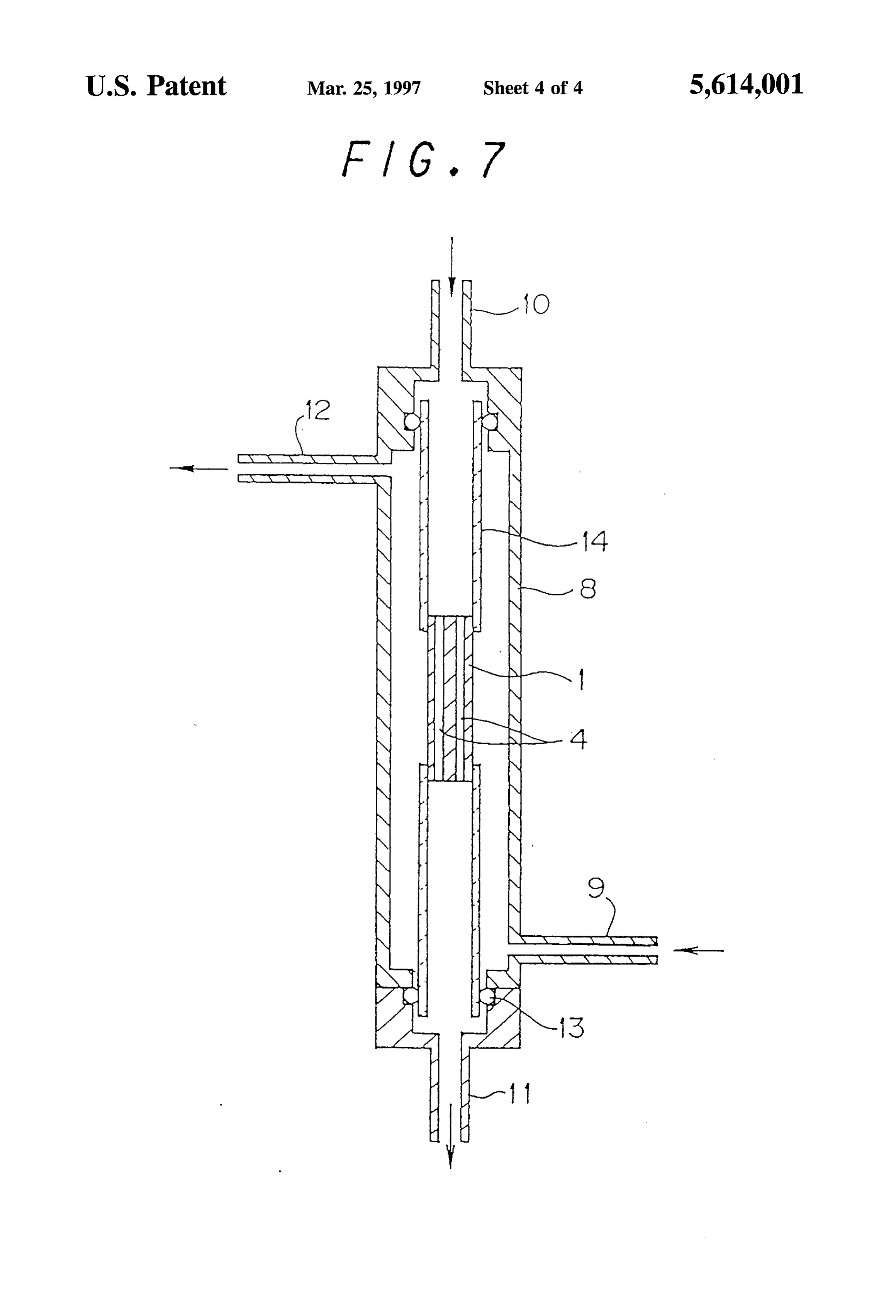
FIG. 3 is an illustrative view showing one embodiment of hand, if it is more than 5um, much time is unpreferably the hydrogen separator of the present invention. taken to cover the inner surfaces of the through-holes 4 with FIG. 4 is an illustrative view showing another embodi the metal having the hydrogen separating ability, and pin ment of the hydrogen separator of the present invention. holes tend to occur through the hydrogen separating films 3. FIG. 5 is an illustrative view showing still another 65 Such a porous substrate can be obtained by a method embodiment of the hydrogen separator of the present inven described in Japanese Patent Application Laid-open No. tion. 273O30/1987.
Page 8
The porcs in the porous substrate 2 preferably have a may be introduced from the outside of the hydrogen sepa small unevenness, because the uniformization of the pore rator or introduced through the through-holes. In either case, diameters permits the easy adjustment of the permeation the hydrogen separator is supported by flanges in a container depth of a plating solution into the porous substrate 2 in an having an inlet for the material gas, an outlet for the activation step or a chemical plating step. hydrogen gas which has permeated through the hydrogen The thickness of the hydrogen separating films 3 is separating films, and another outlet for the gas which has not preferably 50 um or less, more preferably 20 um or less. If permeated through the hydrogen separating films. the thickness of the hydrogen separating films 3 is more than In the case that the material gas is introduced from the 50 um, much time is taken for the material gas to diffuse in outside of the hydrogen separator, the hydrogen separator is the hydrogen separating films 3, so that a treatment time is 10 supported at its one end alone in an overhung state in the unpreferably prolonged. container, whereby a difference of thermal expansion The permeation depth of the metal having the hydrogen between the container and the hydrogen separator can be separating ability into the porous substrate 2 is preferably in absorbed. Furthermore, in the case that the material gas is the range of 1 to 30 um from its surface, more preferably 1 introduced through the through-holes, the material gas is to 20 um, most preferably 1 to 10 pum. If the permeation 15 introduced from part of ends of the through-holes, and the depth of the metal is less than 1 um, the closure of the pores gas which has not permeated through the hydrogen separat with the metal having the hydrogen separating ability is not ing films can be discharged from part of the other ends of the sufficient, so that the material gas might leak into the side of through-holes.
the purified gas; and the hydrogen separating films 3 are also In the case that the material gas is introduced through the liable to separate from the inner surfaces of the through 20 through-holes, and when the material is introduced from the holes 4. On the other hand, if this depth is larger than 30 um, ends of the through-holes and the unpermeated gas is the diffusion time of the material gas is inconveniently discharged from the other ends, the hydrogen separator is prolonged at the time of the hydrogen separation. supported at its end in the container, and both the ends of the When the palladium alloy is used as the metal having the through-holes are required to coincide with the outlet or the hydrogen separating ability, the content of metals other than 25 inlet of the container. In such a case, the hydrogen separator palladium is preferably in the range of 10 to 30% by weight, might be damaged by the difference of the thermal expan as described in "Hydrogen Permeable Palladium-Silver sion between the hydrogen separator and the container, and Alloy Membrane Supported on Porous Ceramics', Journal a structure for connecting the through-holes and the outlet or of Membrane Science, 56, p. 315-325 (1991) and Japanese the inlet of the container might be damaged. In order to Patent Application Laid-open No. 295402/1988. The main purposes of using the palladium alloy are to prevent the 30 expansionsuch prevent troubles, a cushion means for absorbing the of the hydrogen separator is necessary. Such a brittleness of palladium by hydrogen and to improve a means is the installation of a bellowslike thermal expansion separation efficiency at a high temperature. The addition of absorbing portion to the container in view of a fact that the silver to palladium is particularly preferable to prevent the pressure in the through-holes which are on the side of the brittleness of palladium by hydrogen. material gas increases and the pressure on the inside surface Next, a method for manufacturing the hydrogen separator 35 of the container which is on the side of the permeated gas of the present invention will be described. decreases. Another means is the utilization of elastic spiral The manufacturing method can be divided into an acti tubes for connecting the through-holes to the outlet or the vation step or a chemical plating step. inlet of the container.
In the activation step, an activated metal is adsorbed on 40 In both the case that the material gas is introduced from the inner surfaces of the through-holes 4 of the substrate and the outside of the hydrogen separator and the case that the the inside surfaces of the pores present on the inner surfaces. material gas is introduced through the through-holes, the Concretely, the porous substrate is alternately immersed in hydrogen separator is fixed to the container by the flanges, an aqueous tin chloride solution in hydrochloric acid and an which means that the hydrogen separator is supported in an aqueous palladium chloride solution in hydrochloric acid, 45 overhung state.
thereby obtaining suitable results. According to the present invention, the compact hydrogen In the chemical plating step, the interiors of the pores are separator having an improved volume efficiency can be closed and covered with a plating solution containing at least provided as described above, and therefore this hydrogen the metal for covering the substrate and a reducing agent. In separator can be combined with a fuel battery and used as a order to inhibit the occurrence of pinholes and to control the 50 portable power source or a power source for an electrono thickness of the hydrogen separating films, a plating solution bile. Now, there has been investigated a system comprising 6 is forcedly fed to and circulated through the through-holes a fuel battery and a hydrogen producing apparatus which can 4 of the substrate 2 by means of a pump 5 or the like, as produce hydrogen by reforming, with water vapor, methane shown in FIG. 2. In this case, the circulation direction of the of a town gas, a liquid hydrocarbon such as methanol or plating solution can suitably be switched to achieve the 55 ethanol and/or a hydrocarbon containing an oxygen atom as uniformization of the film thickness, and a treatment time a fuel. However, the reformed gas contains about 1% of CO, can be adjusted to control the film thickness. For the switch and this CO poisons Pt which is an electrode catalyst for a of the circulation direction, a four way cock 7 or the like ban phosphate type or a solid polymeric type fuel battery. be suitably used. In the case that a palladium-silver alloy is Particularly in the case of the solid polymeric type fuel used as the metal having the hydrogen separating ability, this 60 battery, even if the concentration of CO is about 10 ppm, Pt alloy is preferably formed as follows. First, palladium is is poisoned with CO. Therefore, it is necessary to lower the subjected to a chemical plating treatment, and the surface of CO concentration to several ppm or less, and hence, the palladium is then chemically plated with silver. In the last combination of a reformer and the hydrogen separator of the place, palladium and silver are allowed to interdiffuse to present invention is desirable. When the hydrogen separator form the alloy. 65 of the present invention is applied to a car, methanol or The above-mentioned hydrogen separator can be used in ethanol is preferable as the fuel, because this kind of fuel is the hydrogen separating apparatus so that the material gas suitable for storage and transport. Moreover, as the fuel
Page 9
battery, there can be used the phosphate type and the solid as that of the through-holes 4 of the hydrogen separator 1 polymeric type fuel battery, but the solid polymeric type fuel and having orifices 27 at their centers, and the container battery is more preferable, because its operation temperature bottom is further stuck and fixed to the end of the hydrogen is as low as 100 C. or less and it is small-sized and separator 1, with the projections being inserted into the lightweight. through-holes 4 of the hydrogen separator 1. The orifices 27 Next, the present invention will be described in more formed at the centers of the circular projections are con detail with reference to embodiments on the basis of nected to the outlet 20.
attached drawings, but the scope of the present invention In order to prevent the hydrogen separating apparatus should not be limited to these embodiments. from being damaged by a difference of thermal expansion FIG. 3 shows one embodiment of a hydrogen separating 10 outer between the container 15 and the hydrogen separator 1, the apparatus using a hydrogen separator of the present inven surface of the container body 16 is constituted in a tion. In FIG. 3, a container 15 is constituted of a container bellowslike state, whereby the extension of the hydrogen body 16 and a lid 17, and it has an inlet 18 for a material gas, separator 1 in its axial direction can be tolerated. The an outlet 19 for a separated hydrogen gas and another outlet bellowslike portion suffers the pressure of the permeated 20 for an unpermeated gas. 15 gas, but this pressure is low, usually in the range of from negative pressure to several kg/cm, and therefore the force
The container body 16 is cylindrical and has a bottom, an which functions to extend the bellows can be ignored. upper opening, the inlet 18 for the material gas on its outer A hydrogen separating apparatus shown in FIG. 5 is a type periphery, and the outlet 20 for the unpermeated gas. In in which the material gas is fed to the through-holes 4 as addition, the container body 16 has an outward lug 21 20 shown in FIG. 4, but the end of the hydrogen separator 1 around the outer peripheral edge of the opening. which is not fixed by the flange 23 is stuck and fixed by the On the other hand, the lid 17 has a lower opening, the flange 24 having orifices 28. These orifices 28 of the flange outlet 19 for the separated hydrogen gas at its central 24 are connected to the outlet 20 for the unpermeated gas via position, and an outward lug 22 around the outer peripheral pipes 29. These pipes 29 are spirally constituted to possess edge of the opening. elasticity, and so by the use of the pipes 29, the extension of 25 the hydrogen separator 1 in the axial direction can be
Fianges 23, 24 are made of a ceramic or a metal and have absorbed, whereby the hydrogen separating apparatus is a disc shape, and it is further equipped with a plurality of prevented from being damaged by the difference of the circular projections having the same diameter as that of the thermal expansion between the container 15 and the hydro through-holes 4 of the hydrogen separator 1. The flange 23 gen separator 1.
has orifices 25 at the centers of the above-mentioned pro 30 A hydrogen separating apparatus shown in FIG. 6 is also jections. The flanges 23, 24 are stuck and fixed to ends of the a type in which the material gas is fed to the through-holes hydrogen separator 1, with the projections being inserted 4 as shown in FIGS. 4 and 5, and the hydrogen separator 1 into the through-holes 4 of the porous substrate 1. is supported in the overhung state in the container 15. The The outer peripheral edge of the flange 23 is airtightly above-mentioned hydrogen separating apparatuses shown in nipped by a gasket or the like and the lugs 21, 22 of the lid 35 FIGS. 4 and 5 have the structure in which the material gas 17 and the container body 16, and the peripheral edge is is introduced from one end of the hydrogen separator and the further fastened and fixed by fixing members 26. unpermeated gas is discharged from the other end thereof, In this way, one end of the hydrogen separator 1 is fixed but in a hydrogen separating apparatus shown in FIG. 6, the in an overhung state to the container 15 via the flange 23. material gas is introduced and the unpermeated gas is One end of each of the through-holes 4 is connected to the 40 discharged from one end of the hydrogen separator. outlet 19 for the separated hydrogen gas via the orifices 25 In the hydrogen separating apparatus shown in FIG. 6, of the flange 23, and the other ends of the through-holes 4 part of the orifices 25 which are opened on the side of the are airtightly sealed by the flange 24. inlet 18 of the through-holes 4 are connected to the inlet 18, The material gas is fed to the hydrogen separating appa and the other orifice is connected to the outlet 20 for the ratus through the inlet 18 for the material gas, and the unpermeated gas. Therefore, the outlet 20 and the inlet 18 hydrogen gas selectively permeates through the hydrogen form a double tube structure. The flange 24 has the orifices separating films 3 formed on the inner surfaces of the 28, and the end of the hydrogen separator 1 is closed, the through-holes 4, flows into the through-holes 4, passes through-holes being connected to each other. through the interior of the lid 17, and then discharges 50 The material gas introduced from the inlet 18 passes through the outlet 19. through the orifices 25 of the flange 24, and then discharges Other embodiments of the hydrogen separating appara through the outlet 20. The hydrogen gas component in the tuses using the hydrogen separator of the present invention material gas permeates through the hydrogen separating are shown in FIGS. 4, 5 and 6. films 3, and then discharges through the outlet 19. In the hydrogen separating apparatus shown in FIG. 4, the 55 Therefore, it is not necessary to link both the ends of the hydrogen separator 1 is supported in an overhung state by hydrogen separator 1 to the container 15, and thus such a the flange 23 in the container 15. In this case, the material cushion means as absorbs the difference of the thermal gas introduced through the inlet 18 gets into the through expansion between the container 15 and the hydrogen sepa holes 4 from the ends of the through-holes 4 through the rator 1 is not required any more. orifices 25 of the flange 23. The hydrogen gas selectively 60 Of the through-holes 4, the through-holes present in the permeates through the hydrogen separating films 3, flows vicinity of the outer surface of the hydrogen separator 1 are out of the hydrogen separator 1, and then discharge through preferably connected to the inlet 18 for the material gas, and the outlet 19. On the other hand, the unpermeated gas is the through-holes present inside the hydrogen separator 1 discharged through the other ends of the through-holes 4 and are preferably connected to the outlet 20 for the unperme then the outlet 20. 65 ated gas.
Therefore, the bottom of the container 16 is equipped with In these hydrogen separating apparatuses, the unperme a plurality of circular projections having the same diameter ated gas discharged through the outlet 20 can be returned to
Page 10
the inlet 18 and then subjected to the separation treatment was adjusted to control the film thickness. The treatment again. In addition, these hydrogen separating apparatuses time was changed so that a weight ratio of palladium:silver may be combined in a multi-stage state. might be 80:20, thereby forming plating films having a film The material for the flanges 23, 24 is required to have no thickness of 20 pum.
breathability, and examples of the usable material include Afterward, the thus plated substrate was held at 900° C. densc ceramics made of alumina, silica, silica-alumina, for 12 hours under an argon atmosphere to carry out a heat mullite, cordierite, Zirconia and the like, and metals such as treatment, whereby palladium and silver were allowed to SUS, Inconel and Kovar, and it is desirable to use the interdiffuse to form an alloy.
material having a thermal expansion coefficient similar to The porous substrate was cut along its axial direction into that of the porous substrate. 1) a length of 3 cm, and the whole porous substrate was then
For a bond between the flanges 23, 24 and the hydrogen sealed with glass except the portions of the through-holes on separator 1, a heat-resistant inorganic bonding agent can be both the ends thereof. Afterward, alumina dense tubes were used, and cxamples of the suitably usable bonding agent attached to both the ends of the porous substrate to obtain a include a cement, a mortar and the like having a thermal 15 hydrogen Separator.
expansion coefficient similar to that of the flanges 23, 24, For the thus obtained hydrogen separator, a hydrogen and a glass and a brazing material having a transition point separation test was carried out. A mixed gas comprising 80% of 550° C. or more. by volume of hydrogen and 20% by volume of carbon Next, the present invention will be described in detail with dioxide was used as a material gas. FIG. 7 shows the reference to examples. 20 schematic view of a test device. A chamber 8 was equipped with the hydrogen separator connected to alumina dense
EXAMPLE 1 tubes 14 and sealed with O-rings 13. In the first place,
A hydrogen separator was prepared as follows. chamber 8 was heated up to 500° C. Next, the mixed gas having a pressure of 9 kg/cm' was introduced into a space
In the first place, a porous substrate was subjected to an around the hydrogen separator 1 through an inlet tube 9 at activation treatment. The porous substrate which was used 25 2N liters/minute (i.e., the volume at room temperature was herein was a cylindrical O-alumina porous material having 2 liters). Furthermore, an argon gas having a pressure of 1 an outcr diameter of 30 mm, a length of 300 mm, a pore kg/cm was fed as a carrier gas to the inner surfaces of the diameter of 0.2 pum and 37 through-holes of 3 mm in through-holes 4 of the hydrogen separator 1 through an inlet diameter.
30 tube 10 at 0.1N liter/minute. For a purified gas obtained
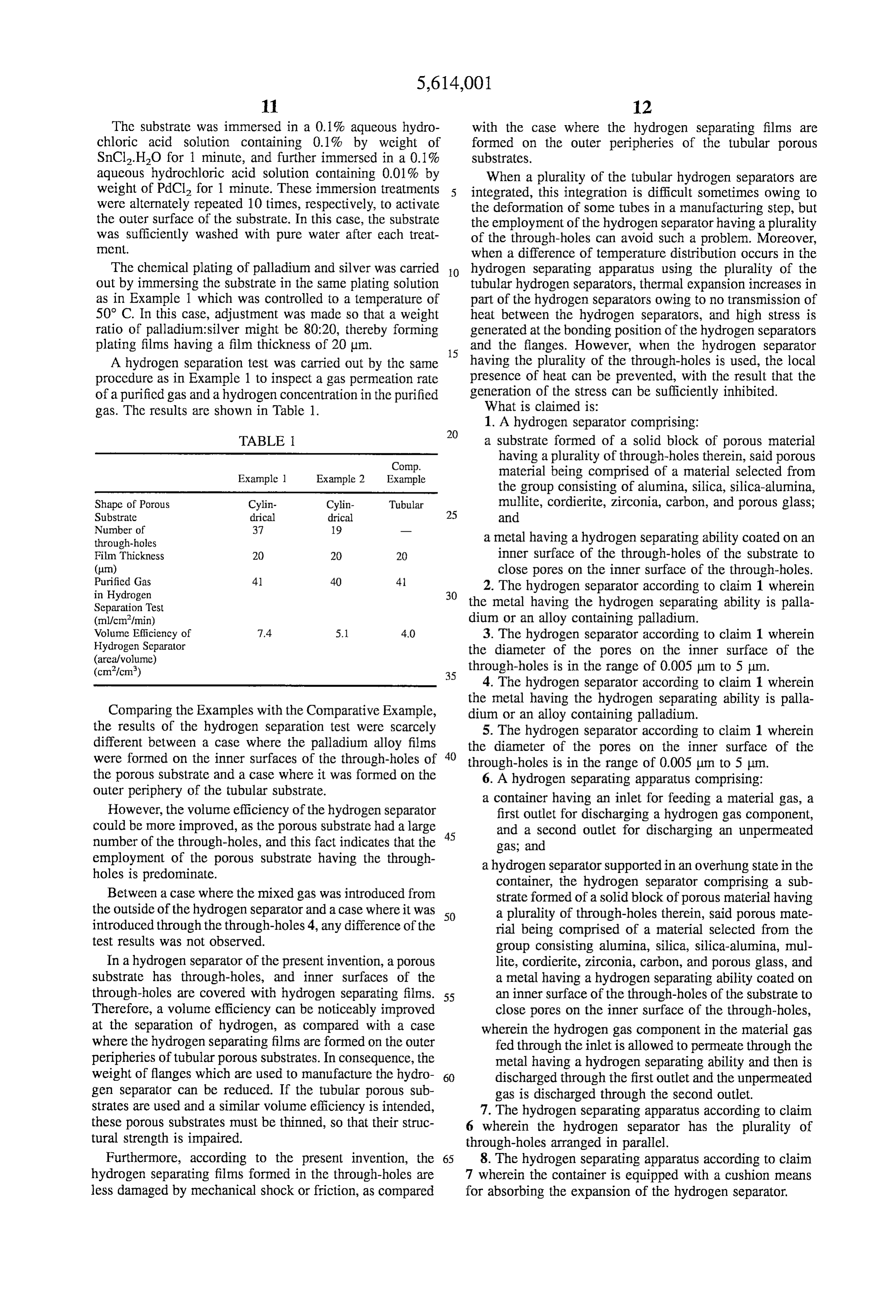
The surfaces of the porous substrate except the inner through an outlet tube 11, quantitative analysis was carried surfaces of the through-holes, i.e., the outer periphery of the out to inspect a gas permeation rate of the purified gas and cylindrical porous substrate and the end surfaces of the a hydrogen concentration in the purified gas. substrate except the portions of the through-holes were The results are shown in Table 1. covered with a sealing tape, and the substrate was then 35 immerscd in a 0.1% aqueous hydrochloric acid solution containing 0.1% by weight of SnCl2.H2O for 1 minute, and EXAMPLE 2 further immersed in a 0.1% aqueous hydrochloric acid A cylindrical O-alumina porous material having an outer solution containing 0.01% by weight of PdCl for 1 minute. diameter of 30 mm, a length of 300 mm, a pore diameter of These immersion treatments were alternately repeated 10 40 0.2 um and 19 through-holes of 4 mm in diameter was used, times, respectively, to activate the inner surfaces of the and the same procedure as in Example 1 was then carried out through-holes. In this case, the substrate was sufficiently to prepare a hydrogen separator. washed with pure water after each treatment. A hydrogen separation test was carried out by the same Next, the substrate was plated with palladium by chemical procedure as in Example 1 to inspect a gas permeation rate plating. That is to say, a plating solution containing 5.4 g of 45 of the purified gas and a hydrogen concentration in the (Pd(NH)Cl.HO, 67.2 g of 2Na.EDTA, 651.3 ml of purified gas. The results are shown in Table 1.
aqueous ammonia having an ammonia concentration of 28% and 0.46 ml of HNNH.HO per liter of deionized water was prepared. This plating solution was placed in a plating EXAMPLE 3 solution tank, and then fed to the inner surfaces of the 50 through-holes of the porous substrate by means of a circu In a test device in a schematic view of FIG.7, a mixed gas lating pump. Furthermore, the circulating direction of the was introduced through an inlet tube 10, and a carrier gas plating solution was switched after a certain time by a four was introduced through an inlet tube 9 to carry out gas way cock to achieve the uniformization of a film thickness, purification. Next, inspection was made for a gas permeation and a treatment time was adjusted to control the film 55 rate of the purified gas obtained through an outlet tube 12 and a hydrogen concentration in the purified gas.
thickness.
Next, the substrate was further plated with silver by The test device which was used herein was the same as in chemical plating. That is to say, a plating solution containing Examples 1 and 2, and the kinds of gases, the introduction 3.46 g of AgNO, 33.6 g of 2Na.EDTA, 651.3 ml of aqueous conditions of the gases and the like were also the same as in ammonia having an ammonia concentration of 28% and 60 Example 1 or 2.
0.46 ml of HNNH.HO per liter of deionized water was prepared. As in the case of palladium, this plating solution Comparative Example was fed to the inner surfaces of the through-holes of the porous substrate by means of the circulating pump. Further A cylindrical O-alumina porous material having an outer more, the circulating direction of the plating solution was 65 diameter of 10 mm, an inner diameter of 7 mm, a length of switched after a certain time by the four way cock to achieve 300 mm and a pore diameter of 0.2 m was used as a porous the uniformization of a film thickness, and a treatment time substrate to prepare a hydrogen separator.
Page 11
The substrate was immersed in a 0.1% aqueous hydro with the case where the hydrogen separating films are chloric acid solution containing 0.1% by weight of formed on the outer peripheries of the tubular porous SnCl2.H2O for 1 minute, and further immersed in a 0.1% Substrates.
aqueous hydrochloric acid solution containing 0.01% by When a plurality of the tubular hydrogen separators are weight of PdCl2 for 1 minute. These immersion treatments integrated, this integration is difficult sometimes owing to were alternately repeated 10 times, respectively, to activate the deformation of some tubes in a manufacturing step, but the outer surface of the substrate. In this case, the substrate the employment of the hydrogen separator having a plurality was Sufficiently washed with pure water after each treat of the through-holes can avoid such a problem. Moreover, Cnt. when a difference of temperature distribution occurs in the The chemical plating of palladium and silver was carried O hydrogen Separating apparatus using the plurality of the out by immersing the substrate in the same plating solution tubular hydrogen separators, thermal expansion increases in as in Example 1 which was controlled to a temperature of part of the hydrogen separators owing to no transmission of 50° C. In this case, adjustment was made so that a weight heat between the hydrogen separators, and high stress is ratio of palladium:silver might be 80:20, thereby forming generated at the bonding position of the hydrogen separators plating films having a film thickness of 20 um. 15 and the flanges. However, when the hydrogen separator A hydrogen separation test was carried out by the same having the plurality of the through-holes is used, the local proccdure as in Example 1 to inspect a gas permeation rate presence of heat can be prevented, with the result that the of a purified gas and a hydrogen concentration in the purified generation of the stress can be sufficiently inhibited. gas. The results are shown in Table 1. What is claimed is:
1. A hydrogen separator comprising:
TABLE a substrate formed of a solid block of porous material
Comp.
having a plurality of through-holes therein, said porous
Example 1 Example 2 Example material being comprised of a material selected from the group consisting of alumina, silica, silica-alumina,
Shape of Porous Cylin- Cylin- Tubular mullite, cordierite, Zirconia, carbon, and porous glass; Substrate drical drical 25 and
through-holes a metal having a hydrogen separating ability coated on an Film Thickness 20 20 20 inner surface of the through-holes of the substrate to
close pores on the inner surface of the through-holes.
in Hydrogen 30 2. The hydrogen separator according to claim 1 wherein
Separation Test the metal having the hydrogen separating ability is palla (ml/cm/min) dium or an alloy containing palladium. Volume Efficiency of 7.4 5.1 40 3. The hydrogen separator according to claim 1 wherein Hydrogen Separator the diameter of the pores on the inner surface of the (areaf volume) (cm/cm) 35 through-holes is in the range of 0.005 um to 5 um.
4. The hydrogen separator according to claim 1 wherein the metal having the hydrogen separating ability is palla
Comparing the Examples with the Comparative Example, dium or an alloy containing palladium. the results of the hydrogen separation test were scarcely 5. The hydrogen separator according to claim 1 wherein different between a case where the palladium alloy films the diameter of the pores on the inner surface of the were formed on the inner surfaces of the through-holes of 40 through-holes is in the range of 0.005 um to 5 m. the porous Substrate and a case where it was formed on the 6. A hydrogen separating apparatus comprising: outer periphery of the tubular substrate. a container having an inlet for feeding a material gas, a However, the volume efficiency of the hydrogen separator first outlet for discharging a hydrogen gas component, could be more improved, as the porous substrate had a large 45 and a second outlet for discharging an unpermeated number of the through-holes, and this fact indicates that the gas; and employment of the porous substrate having the through a hydrogen separator supported in an overhung state in the holes is predominate. container, the hydrogen separator comprising a sub Between a case where the mixed gas was introduced from strate formed of a solid block of porous material having the outside of the hydrogen separator and a case where it was 50 a plurality of through-holes therein, said porous mate introduced through the through-holes 4, any difference of the rial being comprised of a material selected from the test results was not observed. group consisting alumina, silica, silica-alumina, mul In a hydrogen separator of the present invention, a porous lite, cordierite, Zirconia, carbon, and porous glass, and Substrate has through-holes, and inner surfaces of the a metal having a hydrogen separating ability coated on through-holes are covered with hydrogen separating films. 55 an inner surface of the through-holes of the substrate to Therefore, a volume efficiency can be noticeably improved close pores on the inner surface of the through-holes, at the separation of hydrogen, as compared with a case wherein the hydrogen gas component in the material gas where the hydrogen separating films are formed on the outer fed through the inlet is allowed to permeate through the peripheries of tubular porous substrates. In consequence, the metal having a hydrogen separating ability and then is weight of flanges which are used to manufacture the hydro 60 discharged through the first outlet and the unpermeated gen Separator can be reduced. If the tubular porous sub gas is discharged through the second outlet. strates are used and a similar volume efficiency is intended, 7. The hydrogen separating apparatus according to claim these porous substrates must be thinned, so that their struc 6 wherein the hydrogen separator has the plurality of tural strength is impaired. through-holes arranged in parallel.
Furthermore, according to the present invention, the 65 8. The hydrogen separating apparatus according to claim hydrogen separating films formed in the through-holes are 7 wherein the container is equipped with a cushion means less damaged by mechanical shock or friction, as compared for absorbing the expansion of the hydrogen separator.
Page 12
9. The hydrogen separating apparatus according to claim forcedly circulating a plating solution containing a metal 6 wherein the container is equipped with a cushion means having a hydrogen separating ability through the for absorbing the expansion of the hydrogen separator. through-holes of the substrate, whereby an inner sur 10. The hydrogen separating apparatus according to claim face of the through-holes is covered with the metal film 6, whercin the metal having the hydrogen separating ability 5 is palladium or an alloy containing palladium. having the hydrogen separating ability. 11. A mcthod for manufacturing a hydrogen separator by 12. The method for manufacturing a hydrogen separator a chemical plating process, said method comprising the according to claim 11 wherein the plating solution contain steps of: ing the metal having the hydrogen separating ability is providing a substrate formed of a solid block of porous 10 circulated through the through-holes of the substrate by the material having a plurality of through-holes therein, use of a pump, and the direction of the circulation is said porous material being comprised of a material selected from the group consisting of alumina, silica, switched.
silica-alumina, mullite, cordierite, Zirconia, carbon, and porous glass; and
Provenance
- Collection
- Cited prior art
- Original PDF
- patentimages.storage.googleapis.com →
- Filed
- 1995-05-19
- Pages
- 12
- Method
- pdftotext (the PDF's own text layer) + pdftoppm 300dpi page scans
- Source
- Google Patents bibliographic record
- Granted
- 1997-03-25
- Inventors
- Shinichi Kosaka; Osamu Sakai; Tomonori Takahashi; Takao Soma; NGK Insulators Ltd
- Transcribed from
- patentimages.storage.googleapis.com →