patent · US5540831
Electrolytic hydrogen storage and generation
30 July 1996
Page 1 — bibliographic record
United States Patent (19) 11 Patent Number: 5,540,831 Klein 45) Date of Patent: Jul. 30, 1996 (54) ELECTROLYTIC HYDROGEN STORAGE 56 References Cited
AND GENERATION
76 Inventor: Martin Klein, 19 Hillandale Rd., 4,048,383 9/1977 Clifford ................................... 204/129 Brookfield, Conn. 06804 4,174.565 11/1979 Kordesch ............................... 29/623.2 4,702,978 10/1987 Heuts et al. .............................. 429/60 21 Appl. No.: 415,762 4,797,186 1/1989 Levy et al. ......................... 204/DIG. 4
Primary Examiner-Kathryn Gorgos
Related U.S. Application Data Attorney, Agent, or Firm-Robin, Blecker, Daley & Driscoll (63) Continuation of Ser. No. 195,101, Jan. 27, 1994, abandoned, 57 ABSTRACT which is a continuation of Ser. No. 850,459, Mar. 10, 1992, abandoned. Hydrogen storage and generation is accomplished using an (51) Int. Cl." .......................... C25B 1/02; C25B 11/00 electrolytic cell which employs an inert gas electrode, a 52) U.S. Cl. .......................... 205/630; 204/242; 204/291; rechargeable battery electrode having an active material 204/293; 204/294; 429/60; 429/206; 429/221; which stores hydrogen or is close to the potential of hydro 429/225; 205/638; 425/218; 425/231 gen, and a sealed housing which houses the electrodes, a separator and an aqueous electrolyte and has a port for (58 Field of Search ..................................... 204/129, 242, extracting hydrogen generated in the cell.
205/637, 638,630 20 Claims, 6 Drawing Sheets
(CATH ODE)
BATTERY ELECTRODE3 CELL JAR
(ANODE)
ELECTROLYTIC CELL
Page 2
GAS
(CATHODE)
BATTERY ELECTRODE3 CELL JAR
(ANODE)
ELECTROLYTC CELL
CHA GE M(OH)2 -- 2e to sm no as on map a-e- M 2OH
DSCHARGE
COMBINED
REACTIONS
Page 3
Drawing sheet — no readable text.
Page 4
Drawing sheet — no readable text.
Page 5
Drawing sheet — no readable text.
Page 6
Drawing sheet — no readable text.
Page 7
Drawing sheet — no readable text.
Page 8
ELECTROLYTIC HYDROGEN STORAGE The apparatus of the invention thus permits selective AND GENERATION storage and generation of hydrogen in a compact, economi cal cell which is easily transportable.
This is a continuation application under 37 CFR 1.62 of prior application Ser. No. 08/195,101, filed Jan. 27, 1994, BRIEF DESCRIPTION OF THE DRAWINGS now abandoned, which is a continuation of Ser. No. 07/850, The above and other features and aspects of the present 459, filed Mar. 10, 1992, abandoned. invention will become more apparent upon reading the
BACKGROUND OF THE INVENTION
following detailed description in conjunction with the
accompanying drawings, in which:
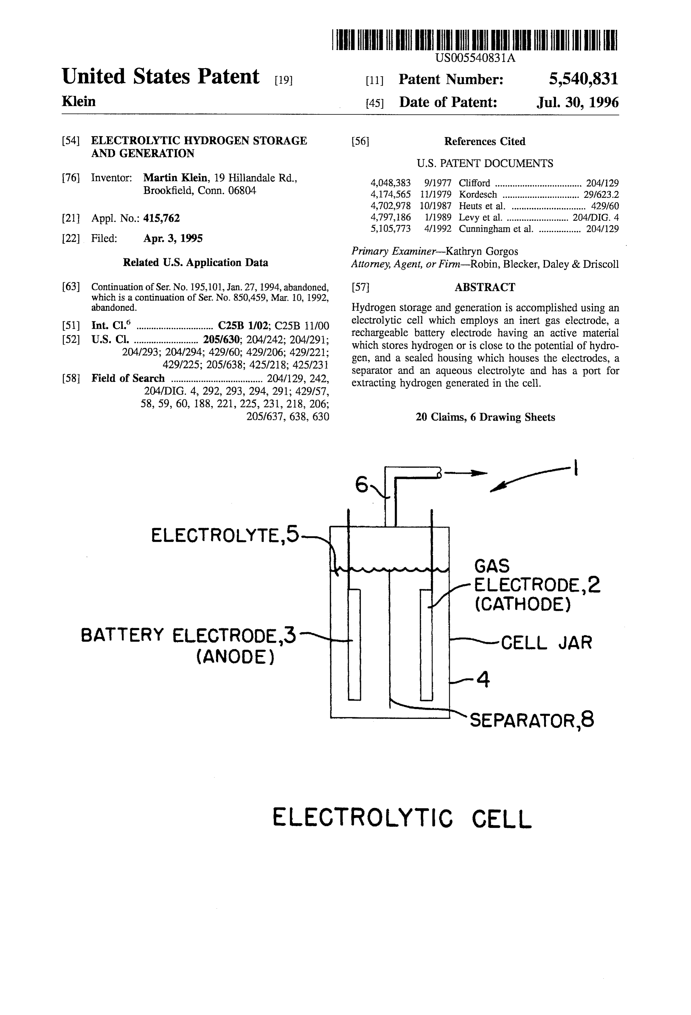
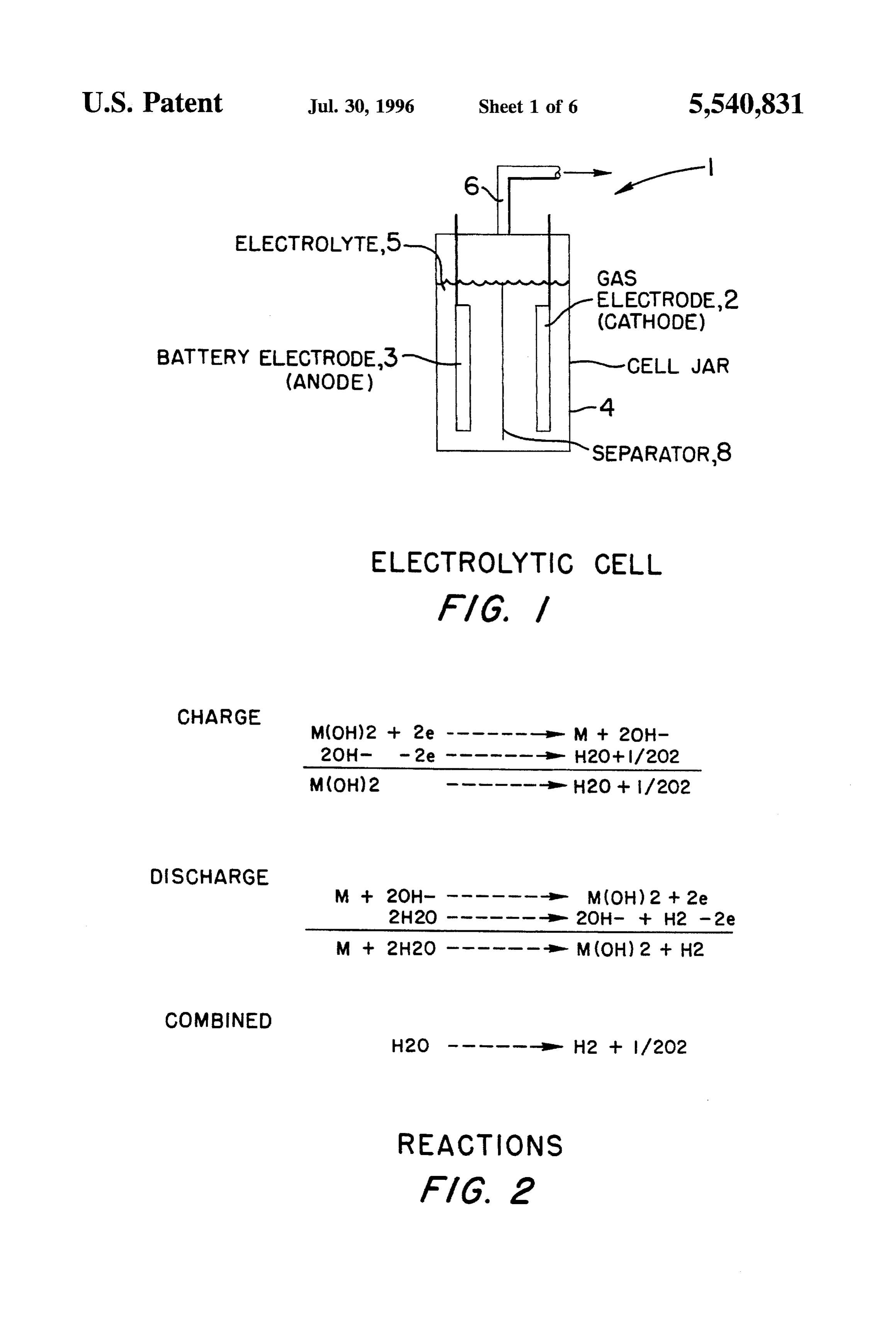
This invention relates to hydrogen and, in particular, to an FIG. 1 shows a hydrogen storage and generation appara apparatus and method for generating and storing hydrogen. tus in accordance with the principles of the present inven Hydrogen is recognized as an ideal fuel in many respects. tion:
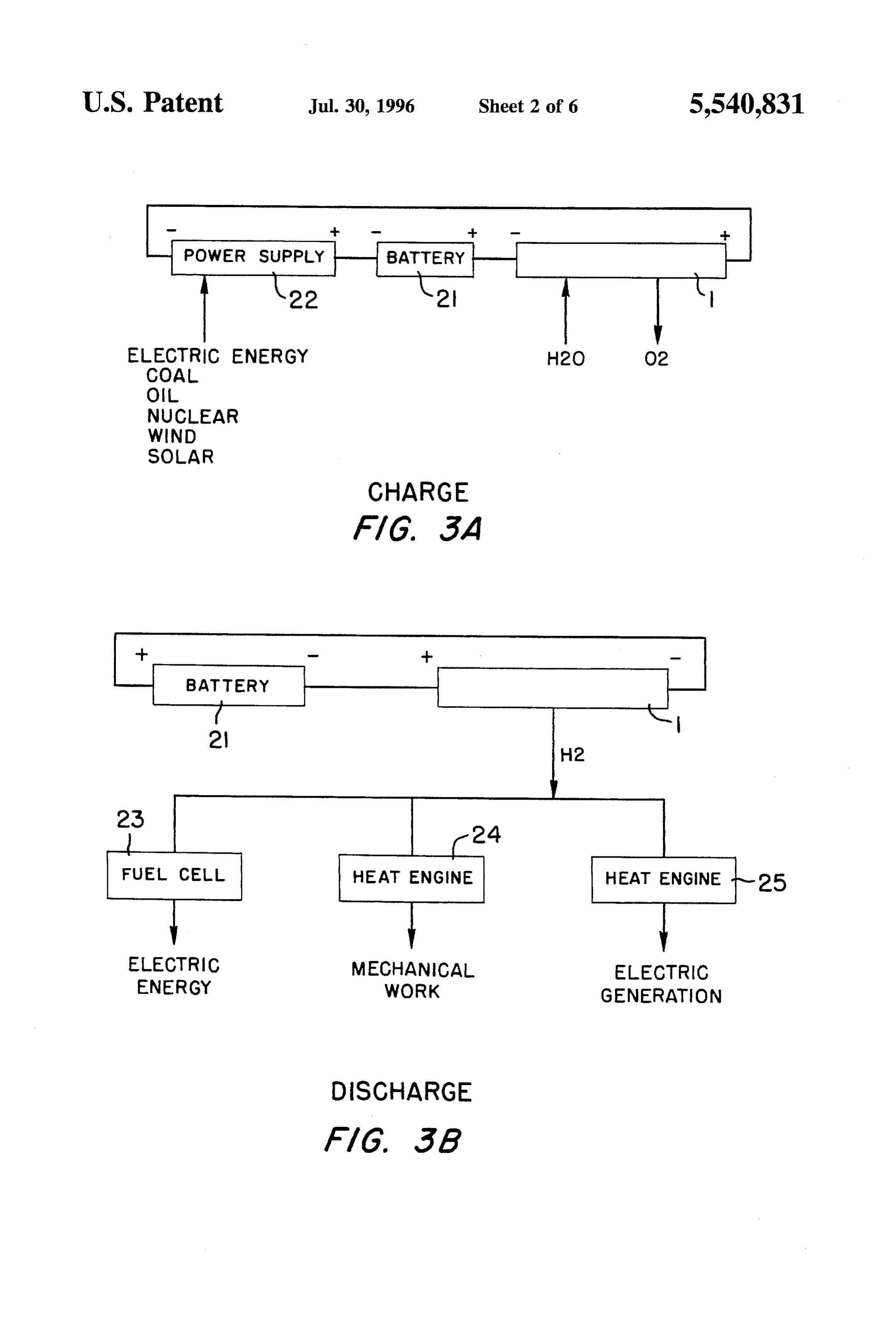
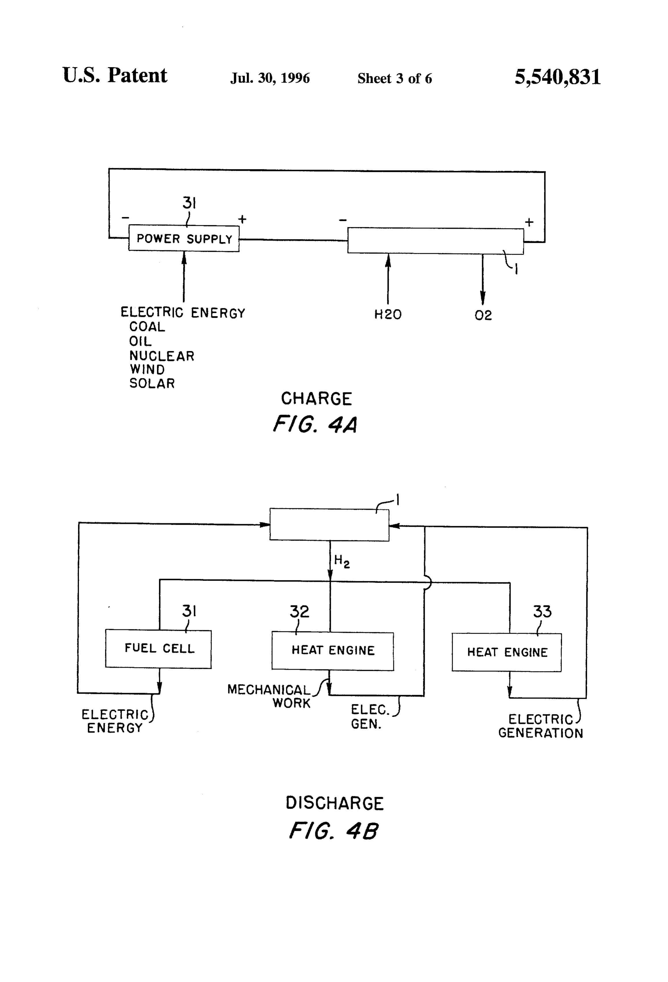
Thus, it is abundantly available in nature, clean burning, FIG. 2 shows the electrochemical reactions in the appa benign as a reaction product and has a high energy content. 15 ratus of FIG. 1 during charge and discharge; It is also capable of direct reaction in fuel cells. However, FIGS. 3A and 3B illustrate a first configuration of a hydrogen has not found wide acceptance as a fuel primarily system utilizing the hydrogen storage and generation appa due to the difficulty of transporting and storing it in a ratus of the invention, compact cost effective manner. FIGS. 4A and 4B illustrate a second configuration of a Hydrogen is normally produced by the reforming of coal 20 System utilizing the hydrogen storage and generation appa or hydrocarbon fuels, the dissociation of ammonia, as a ratus of the invention;
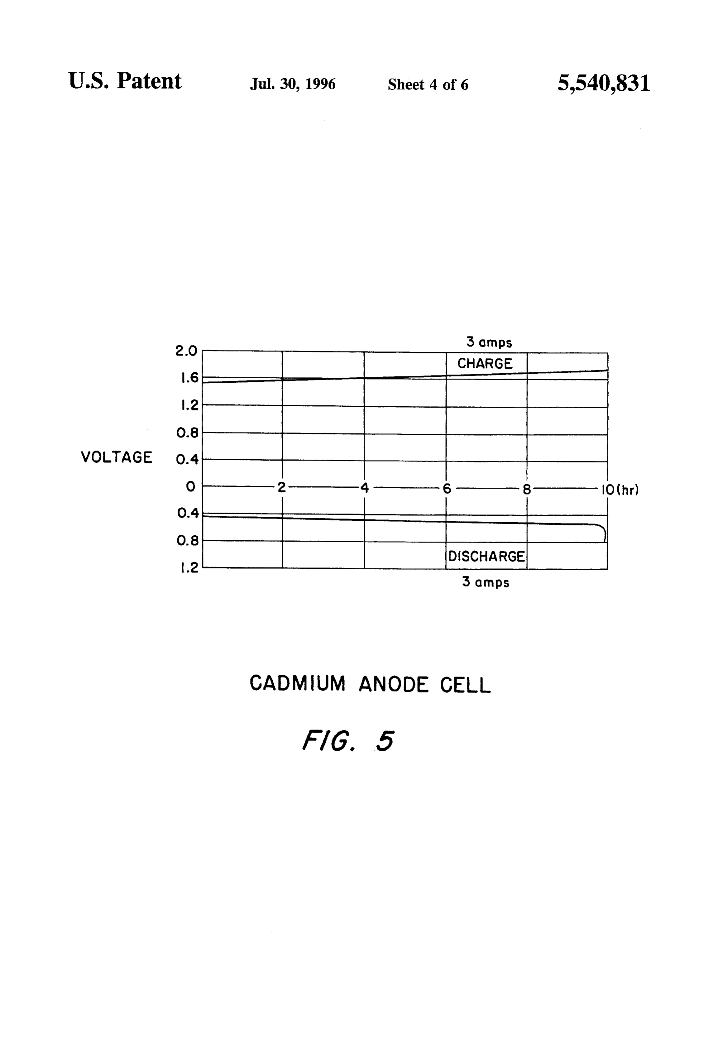
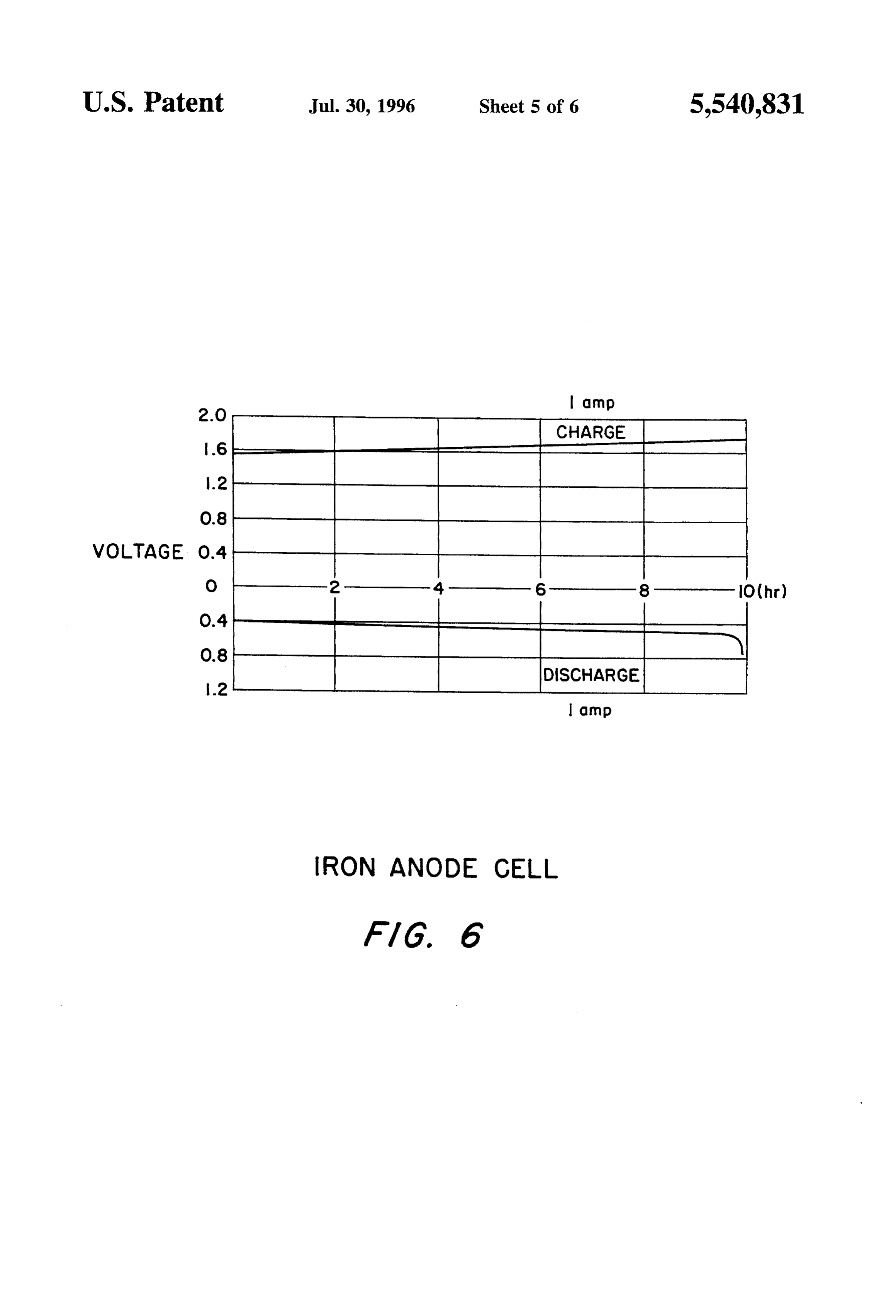
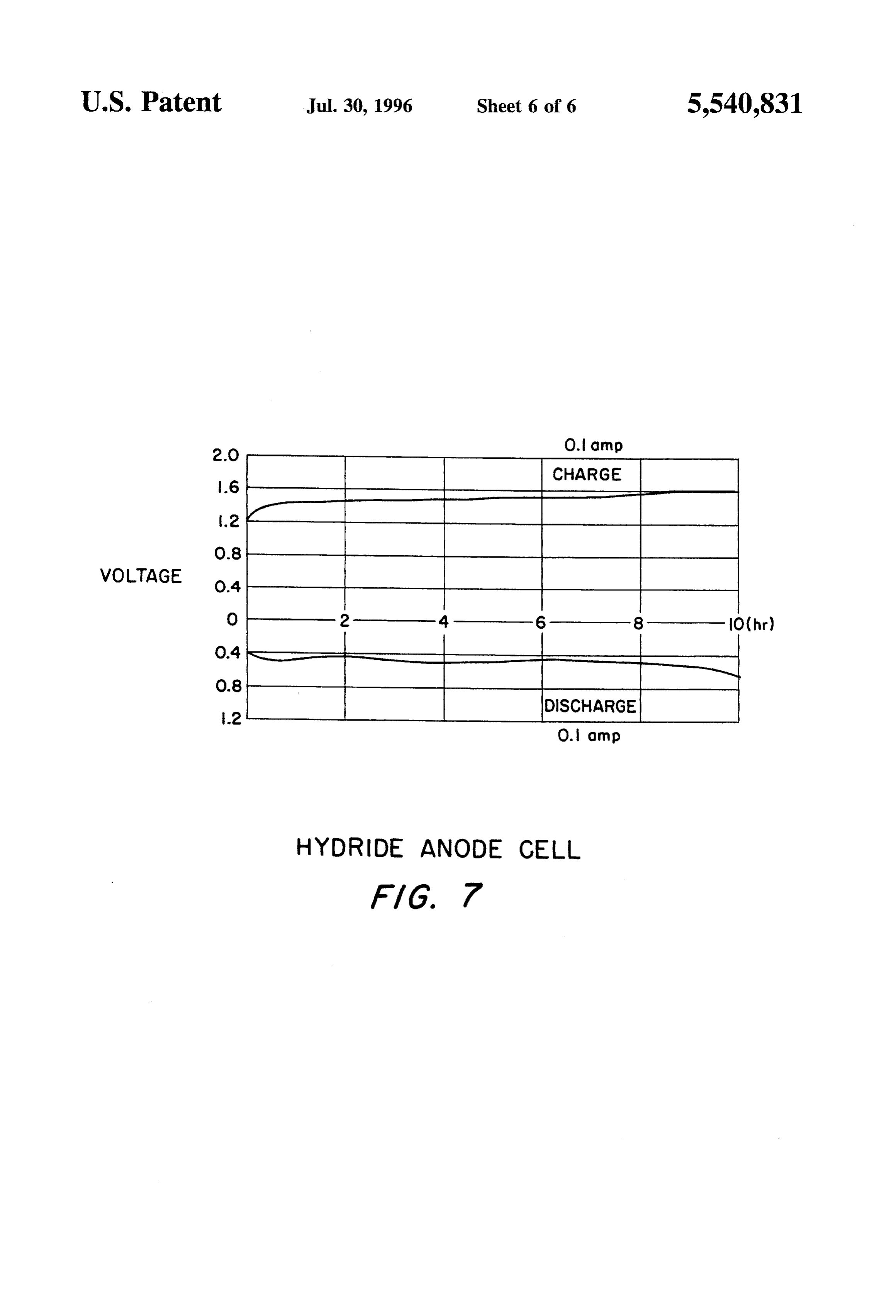
biproduct of chemical processes and by the electrolysis of FIG. 5 shows the charge and discharge voltage of a first water. In water electrolysis, a D.C. current is passed through illustrative example of the apparatus of FIG. 1; an electrolytic cell consisting of two gas evolution elec trodes, and water is dissociated to simultaneously produce 25 FIG. 6 shows the charge and discharge voltage of a second hydrogen and oxygen gas. The water electrolysis reaction is illustrative example of the apparatus of FIG. 1; and as follows: FIG. 7 shows the charge and discharge voltage of a third illustrative example of the apparatus of FIG. 1.
Once generated, hydrogen is typically stored in the liq uified state below -253 degrees C. or as a compressed gas FIG. 1 shows a hydrogen storage and generation appara at pressures up to 5000 psi. More recently, metal hydrides tus 1 in accordance with the principles of the present have been considered as a hydrogen storage media. How invention. The apparatus i is in the form of an electrolytic ever, all these storage methods are expensive, consume 35 cell which comprises a first inert gas evolution electrode 2 energy, and are hazardous under certain conditions. of a type normally used in electrolysis cells. Preferably, the It is, therefore, a primary object of the present invention gas electrode comprises materials and or catalysts that to provide a compact, safe, low cost hydrogen storage and exhibit stable low gas evolution voltages, i.e. spinels, raney generation technique. nickel, nickel/molybdenum, and platinum family catalysts.
The apparatus also comprises a second electrode 3 which is
SUMMARY OF THE INVENTION a battery-type electrode. The electrode 3 includes an active material which is electrochemically reversible in aqueous
In accordance with the principles of the present invention, electrolytes and stores hydrogen or is close to the potential the above and other objective are realized in an apparatus of hydrogen. In the case shown in FIG. 2, the electrode and method in which an electrolytic cell is employed and in includes a hydroxide of a generic active material M. which the electrolytic cell utilizes an inert gas electrode and 45 The apparatus 1 also includes a sealed housing 4 which a battery-type electrode. The battery-type electrode com contains the electrodes 2, 3, a separator 8 and an aqueous prises an active material which absorbs hydrogen or is close electrolyte 5. A port 6 in the housing allows oxygen and to the potential of hydrogen. hydrogen gas generated in the apparatus i as described The electrolytic cell also includes a sealed housing for the 50 below to be extracted from the apparatus. gas and battery electrodes. An electrolyte and separator are When the electrodes 2 and 3 are subjected to a charging included in the housing with the electrodes, and the housing potential at a preselected voltage, the water in the electrolyte is provided with a gas port for enabling hydrogen to be 5 is dissociated to evolve oxygen at the cathode or gas extracted from the housing. electrode 2. The evolved oxygen is then vented from the With this configuration for the apparatus, when a charging 55 housing 4 via the port 6. The anode or battery electrode, in potential is applied across the electrodes, the water in the turn, is reduced or hydrogen is stored. When the electrodes electrolyte is disassociated to evolve oxygen at the cathode are then subjected to a discharging potential (a potential in or inert gas electrode which is vented from the housing. In the opposite direction to the charging potential) hydrogen is the meantime, the anode or battery electrode active material evolved from the gas or cathode electrode 2 and the anode is reduced or stores hydrogen at the anode. 60 or battery electrode 3 is stripped of hydrogen or oxidized. In If hydrogen is now to be released from the apparatus, a the overall process, water is disassociated to form oxygen discharging potential reverse to the charging potential is now during charge and hydrogen during discharge. FIG. 2 shows applied across the cell electrodes. As a result, the anode or these reactions of the apparatus 1 for the generic active battery electrode is now oxidized or stripped of its stored material M.
hydrogen. The stripped hydrogen is now evolved from the 65 In the apparatus 1, oxygen and hydrogen gases are gen gas electrode and extracted from the apparatus through the erated separately during the different charge and discharge gas port. stages and most or all of the energy is required during the
Page 9
oxygen generation stage. This is in contrast to a water pressed rechargeable cadmium battery electrodes. Each electrolysis system in which hydrogen and oxygen gases are electrode measured 3 inches by 4 inches and combined had simultaneously, continuously generated at a relatively con nominally 30 ampere hours of cadmium capacity. A non stant power input for a given gas output. Like the electroly woven nylon absorber separator material was placed on the sis system, the apparatus 1 consumes water which must be cadmium electrodes and a plastic spacer was placed between replaced periodically to insure stable operation. the these electrodes and the gas counter electrodes. Four Table I below is a list of active materials M which can be nickel screens of the same size of the cadmium electrodes used as the anode or battery electrode 3 of the FIG. 1 were used as the latter gas electrodes. The cell was filled apparatus. with an electrolyte of 35% KOH. The cell was charged and 10 discharged using a commercial D.C. power supply powered
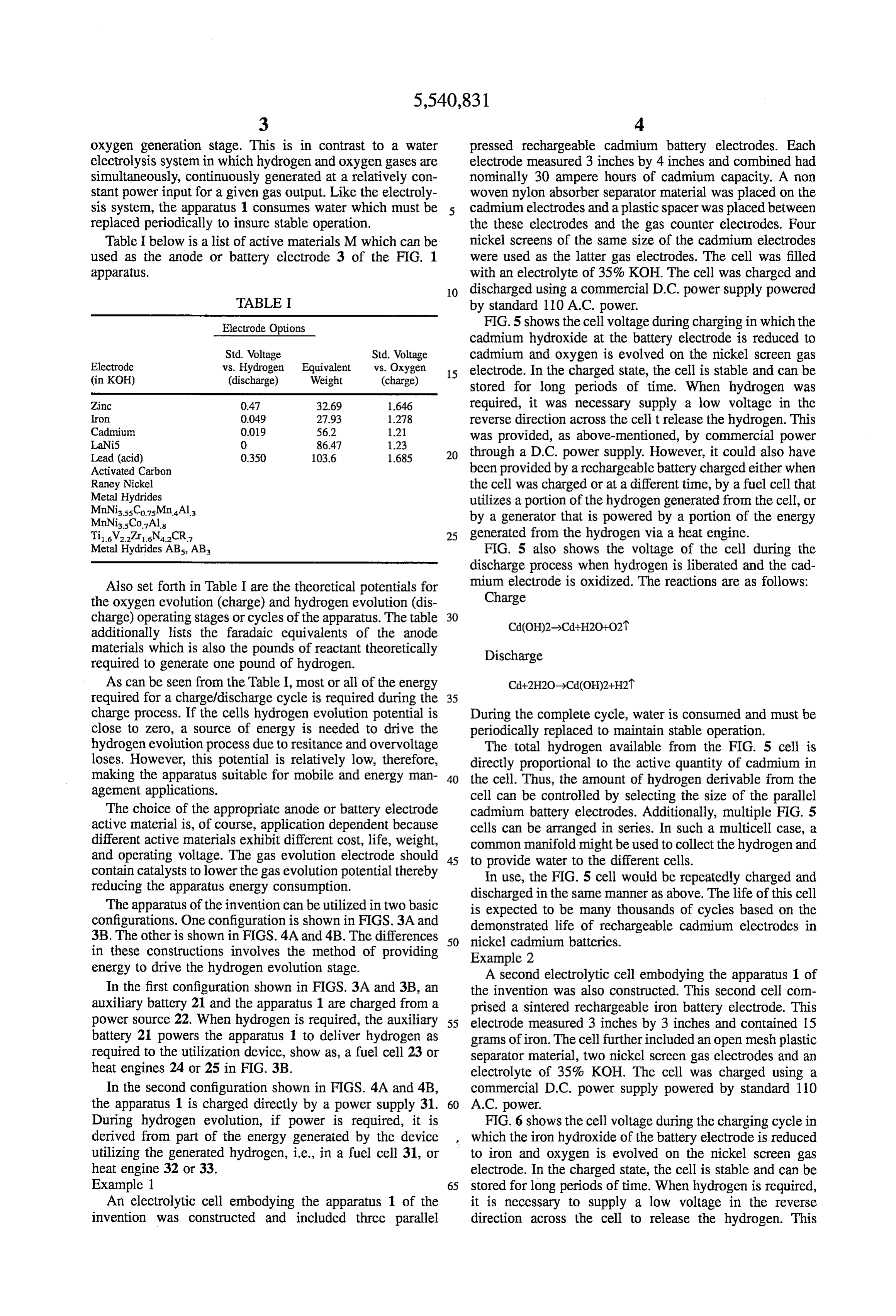
TABLE I by standard 110 A.C. power.
Electrode Options FIG. 5 shows the cell voltage during charging in which the cadmium hydroxide at the battery electrode is reduced to
Electrode
Std. Voltage vs. Hydrogen Equivalent
Std. Voltage cadmium and oxygen is evolved on the nickel screen gas vs. Oxygen 15 electrode. In the charged state, the cell is stable and can be (in KOH) (discharge) Weight (charge) stored for long periods of time. When hydrogen was
Zinc 0.47 32.69 1646 required, it was necessary supply a low voltage in the Iron
Cadmium
reverse direction across the cell t release the hydrogen. This
LaNiS O 86.41 1.23 was provided, as above-mentioned, by commercial power
Lead (acid) 0.350 103.6 1685 20 through a D.C. power supply. However, it could also have Activated Carbon been provided by a rechargeable battery charged either when Raney Nickel the cell was charged or at a different time, by a fuel cell that Metal Hydrides utilizes a portion of the hydrogen generated from the cell, or MnNiassCo.75Mn Ala by a generator that is powered by a portion of the energy MnNi35Co. Als
Tii.6V227r1.6N4.2CR7 25 generated from the hydrogen via a heat engine. Metal Hydrides AB, AB FIG. 5 also shows the voltage of the cell during the discharge process when hydrogen is liberated and the cad
Also set forth in Table I are the theoretical potentials for mium electrode is oxidized. The reactions are as follows: the oxygen evolution (charge) and hydrogen evolution (dis Charge charge) operating stages or cycles of the apparatus. The table 30 additionally lists the faradaic equivalents of the anode materials which is also the pounds of reactant theoretically required to generate one pound of hydrogen.
As can be seen from the Table I, most or all of the energy required for a charge/discharge cycle is required during the 35 charge process. If the cells hydrogen evolution potential is During the complete cycle, water is consumed and must be close to Zero, a source of energy is needed to drive the periodically replaced to maintain stable operation. hydrogen evolution process due to resitance and overvoltage The total hydrogen available from the FIG. 5 cell is loses. However, this potential is relatively low, therefore, directly proportional to the active quantity of cadmium in making the apparatus suitable for mobile and energy man 40 the cell. Thus, the amount of hydrogen derivable from the agement applications. cell can be controlled by selecting the size of the parallel The choice of the appropriate anode or battery electrode cadmium battery electrodes. Additionally, multiple FIG. 5 active material is, of course, application dependent because cells can be arranged in series. In such a multicell case, a different active materials exhibit different cost, life, weight, common manifold might be used to collect the hydrogen and and operating voltage. The gas evolution electrode should 45 to provide water to the different cells. contain catalysts to lower the gas evolution potential thereby In use, the FIG. 5 cell would be repeatedly charged and reducing the apparatus energy consumption. discharged in the same manner as above. The life of this cell The apparatus of the invention can be utilized in two basic is expected to be many thousands of cycles based on the configurations. One configuration is shown in FIGS. 3A and demonstrated life of rechargeable cadmium electrodes in 3B. The other is shown in FIGS. 4A and 4.B. The differences 50 nickel cadmium batteries.
in these constructions involves the method of providing Example 2 energy to drive the hydrogen evolution stage. A second electrolytic cell embodying the apparatus 1 of In the first configuration shown in FIGS. 3A and 3B, an the invention was also constructed. This second cell com auxiliary battery 21 and the apparatus 1 are charged from a prised a sintered rechargeable iron battery electrode. This power source 22. When hydrogen is required, the auxiliary 55 electrode measured 3 inches by 3 inches and contained 15 battery 21 powers the apparatus 1 to deliver hydrogen as grams of iron. The cell further included an open mesh plastic required to the utilization device, show as, a fuel cell 23 or separator material, two nickel screen gas electrodes and an heat engines 24 or 25 in FIG. 3B. electrolyte of 35% KOH. The cell was charged using a In the second configuration shown in FIGS. 4A and 4B, commercial D.C. power supply powered by standard 110 the apparatus 1 is charged directly by a power supply 31. 60 A.C. power.
During hydrogen evolution, if power is required, it is FIG. 6 shows the cell voltage during the charging cycle in derived from part of the energy generated by the device which the iron hydroxide of the battery electrode is reduced utilizing the generated hydrogen, i.e., in a fuel cell 31, or to iron and oxygen is evolved on the nickel screen gas heat engine 32 or 33. electrode. In the charged state, the cell is stable and can be Example 1 65 stored for long periods of time. When hydrogen is required, An electrolytic cell embodying the apparatus 1 of the it is necessary to supply a low voltage in the reverse invention was constructed and included three parallel direction across the cell to release the hydrogen. This
Page 10
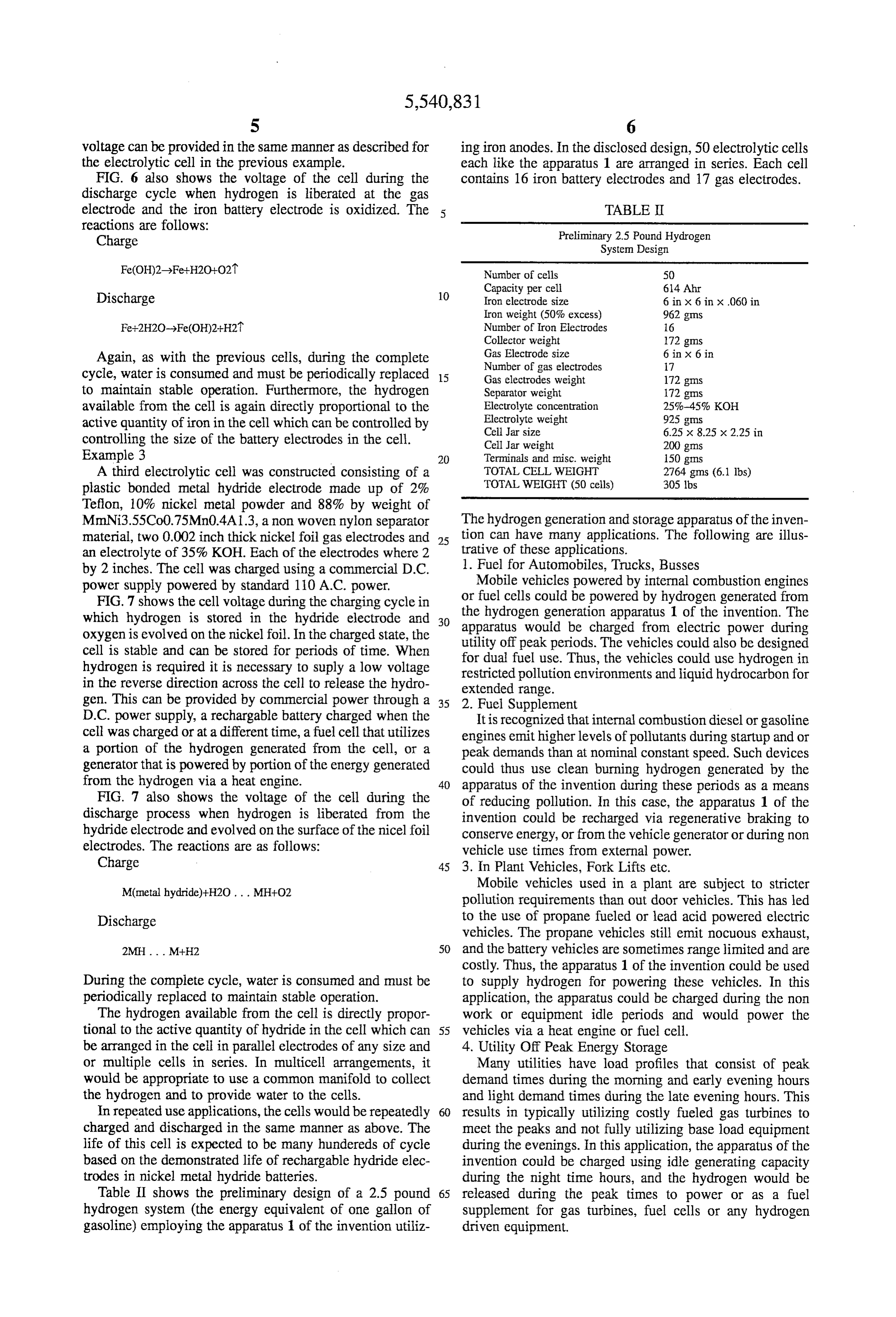
voltage can be provided in the same manner as described for ing iron anodes. In the disclosed design, 50 electrolytic cells the electrolytic cell in the previous example. each like the apparatus 1 are arranged in series. Each cell FIG. 6 also shows the voltage of the cell during the contains 16 iron battery electrodes and 17 gas electrodes. discharge cycle when hydrogen is liberated at the gas electrode and the iron battery electrode is oxidized. The TABLE II reactions are follows:
Charge Preliminary 2.5 Pound Hydrogen System Design
10 Iron electrode size 6 in x 6 in x.060 in
Number of Iron Electrodes 16
Again, as with the previous cells, during the complete Gas Electrode size 6 in x 6 in Number of gas electrodes 17 cycle, water is consumed and must be periodically replaced 15 Gas electrodes weight 172 gms to maintain stable operation. Furthermore, the hydrogen Separator weight 172 gms available from the cell is again directly proportional to the Electrolyte concentration 25%-45% KOH active quantity of iron in the cell which can be controlled by Electrolyte weight 925 gms
controlling the size of the battery electrodes in the cell. Cell Jar weight 200 gms Example 3 20 Terminals and misc. weight 150gms A third electrolytic cell was constructed consisting of a TOTAL CELL WEIGHT 2764 gms (6.1 lbs) plastic bonded metal hydride electrode made up of 2% TOTAL WEIGHT (50 cells) 305 lbs Teflon, 10% nickel metal powder and 88% by weight of
MmNi3.55Co0.75Mn0.4A1.3, a non woven nylon separator The hydrogen generation and storage apparatus of the inven material, two 0.002 inch thick nickel foil gas electrodes and 25 tion can have many applications. The following are illus an electrolyte of 35% KOH. Each of the electrodes where 2 trative of these applications. by 2 inches. The cell was charged using a commercial D.C. 1. Fuel for Automobiles, Trucks, Busses power supply powered by standard 110 A.C. power. Mobile vehicles powered by internal combustion engines FIG. 7 shows the cell voltage during the charging cycle in or fuel cells could be powered by hydrogen generated from which hydrogen is stored in the hydride electrode and 30 the hydrogen generation apparatus 1 of the invention. The apparatus would be charged from electric power during oxygen is evolved on the nickel foil. In the charged state, the utility off peak periods. The vehicles could also be designed cell is stable and can be stored for periods of time. When for dual fuel use. Thus, the vehicles could use hydrogen in hydrogen is required it is necessary to suply a low voltage restricted pollution environments and liquid hydrocarbon for in the reverse direction across the cell to release the hydro extended range.
gen. This can be provided by commercial power through a 35 2. Fuel Supplement
D.C. power supply, a rechargable battery charged when the It is recognized that internal combustion diesel or gasoline cell was charged or at a different time, a fuel cell that utilizes engines emit higher levels of pollutants during startup and or a portion of the hydrogen generated from the cell, or a peak demands than at nominal constant speed. Such devices generator that is powered by portion of the energy generated could thus use clean burning hydrogen generated by the from the hydrogen via a heat engine. 40 apparatus of the invention during these periods as a means FIG. 7 also shows the voltage of the cell during the of reducing pollution. In this case, the apparatus 1 of the discharge process when hydrogen is liberated from the invention could be recharged via regenerative braking to hydride electrode and evolved on the surface of the nicel foil conserve energy, or from the vehicle generator or during non electrodes. The reactions are as follows: vehicle use times from external power. Charge 45 3. In Plant Vehicles, Fork Lifts etc. M(metal hydride)+H2O. . . MH+O2 Mobile vehicles used in a plant are subject to stricter pollution requirements than out door vehicles. This has led
Discharge to the use of propane fueled or lead acid powered electric vehicles. The propane vehicles still emit nocuous exhaust, 2MH. M+H2 50 and the battery vehicles are sometimes range limited and are costly. Thus, the apparatus 1 of the invention could be used
During the complete cycle, water is consumed and must be to supply hydrogen for powering these vehicles. In this periodically replaced to maintain stable operation. application, the apparatus could be charged during the non The hydrogen available from the cell is directly propor work or equipment idle periods and would power the tional to the active quantity of hydride in the cell which can 55 vehicles via a heat engine or fuel cell. be arranged in the cell in parallel electrodes of any size and 4. Utility Off Peak Energy Storage or multiple cells in series. In multicell arrangements, it Many utilities have load profiles that consist of peak would be appropriate to use a common manifold to collect demand times during the morning and early evening hours the hydrogen and to provide water to the cells. and light demand times during the late evening hours. This In repeated use applications, the cells would be repeatedly 60 results in typically utilizing costly fueled gas turbines to charged and discharged in the same manner as above. The meet the peaks and not fully utilizing base load equipment life of this cell is expected to be many hundereds of cycle during the evenings. In this application, the apparatus of the based on the demonstrated life of rechargable hydride elec invention could be charged using idle generating capacity trodes in nickel metal hydride batteries. during the night time hours, and the hydrogen would be Table II shows the preliminary design of a 2.5 pound 65 released during the peak times to power or as a fuel hydrogen system (the energy equivalent of one gallon of supplement for gas turbines, fuel cells or any hydrogen gasoline) employing the apparatus 1 of the invention utiliz driven equipment.
Page 11
5. Standby Power Supplies 5. Apparatus in accordance with claim 4 wherein; Due to unpredicted power interruption, many electric said means for applying a discharging potentional com users install standby electric generation equipment to meet prises a DC battery.
emergencies. These typically consist of batteries, gasoline 6. Apparatus in accordance with claim 5 wherein: generators or diesel generators. The latter two are difficult to said means for applying a charging potential comprises a maintain due to the use of hydrocarbon fuels, are unreliable AC source which feeds said DC battery and said and emit pollutants and the batteries are sometimes capacity electrodes.
limited. In this application, the apparatus 1 of the invention 7. Apparatus in accordance with claim 4 wherein: could provide clean hydrogen to the power generating said means for applying said discharging potential com equipment during the power outages.
6. Solar, Wind Energy Storage 10 prises a hydrogen utilization device which utilizes said
Solar and wind power generators provide intermittent hydrogen when extracted from said assembly. power due to the erratic nature of their primary source of 8. Apparatus in accordance with claim 1 wherein: power. To provide non interruptible power, they have to be said electrolyte is KOH.
connected to the electric grid or have an energy storage 15 9. Apparatus in accordance with claim 1 wherein: subsystem. The apparatus of the invention could provide said gas electrode comprises a nickel screen, a spinel energy storage by being charged when energy is available catalyst, raney nickel, nickel/molybdenum, or platinum and feed hydrogen to a heat engine or fuel cell generator family metals.
during the non operating periods of the solar or wind 10. Apparatus in accordance with claim 1 further com generators. prising:
7. Chemical Hydrogen a utilization device for using the hydrogen extracted from Hydrogen is used as a coolant, inert cover gas and in many said assembly, said utilization device including one or other chemical processes. The apparatus of the invention more of the following: a fuel cell, an internal combus could be operated to deliver hydrogen on demand for these tion engine, a gas turbine and a heat engine. applications. If steady state hydrogen is required, two sys 25 11. A method comprising:
tems can be alternately charged and discharged. providing an assembly for storing and generating hydro In all cases, it is understood that the above-described gen including: an inert gas electrode; a rechargeable arrangements are merely illustrative of the many possible battery electrode containing an active material which specific embodiments which represent applications of the Stores hydrogen during charging and which releases present invention. Numerous and varied other arrangements, 30 Stored hydrogen during discharging; a sealed housing can be readily devised in accordance with the principles of containing said gas and battery electrodes and which the present invention without departing from the spirit and receives an aqueous electrolyte, said housing including scope of the invention. a port for extracting hydrogen from said assembly What is claimed is: during discharging;
1. An apparatus comprising: 35 and extracting hydrogen from said assembly during dis an assembly for storing and generating hydrogen includ charging.
1ng: 12. A method in accordance with claim 11 wherein: an inert gas electrode; said active material includes at least one of the following: a rechargeable battery electrode containing an active a material including zinc, a material including iron, a material which stores hydrogen during charging and 40 material including cadmium, a material including which releases stored hydrogen during discharging; LaNi5, a material including lead, a material including a sealed housing containing said gas and battery elec activated carbon, a material including raney nickel and trodes and which receives an aqueous electrolyte, said a material including metal hydrides. housing including a port for extracting hydrogen from 45 13. A method in accordance with claim 12 wherein: said assembly during discharging. said material including zinc is zinc hydroxide, said mate 2. Apparatus in accordance with claim 1 wherein: rial including cadmium is cadmium hydroxide, said said active material includes at least one of the following: material including iron is iron hydroxide and said a material including zinc, a material including iron, a material including lead is lead hydroxide. material including cadmium, a material including 50 14. A method in accordance with claim 11 wherein: LaNi5, a material including lead, a material including said method further includes: applying a charging poten activated carbon, a material including raney nickel and tial to said electrodes to evolve oxygen gas at said gas a material including metal hydrides. electrode and to reduce said battery electrode to store 3. Apparatus in accordance with claim 2 wherein: hydrogen; and applying a discharging potential to said said material including zinc is zinc hydroxide, said mate 55 electrodes to oxidize said battery electrode to release rial including cadmium is cadmium hydroxide, said Stored hydrogen and evolve hydrogen gas at said gas material including iron is iron hydroxide and said electrode for extraction from said assembly through material including lead is lead hydroxide. said port.
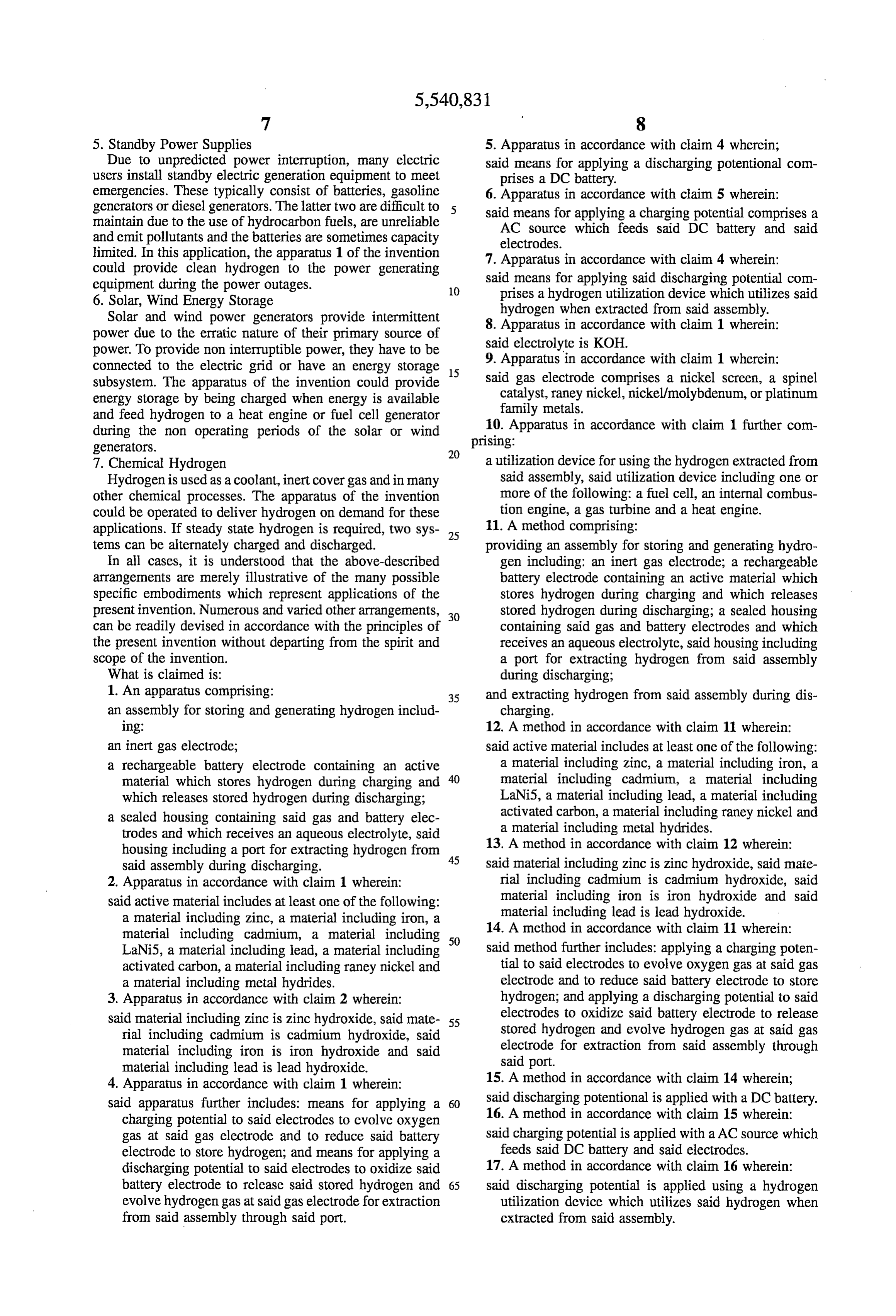
4. Apparatus in accordance with claim 1 wherein: 15. A method in accordance with claim 14 wherein; said apparatus further includes: means for applying a 60 said discharging potentional is applied with a DC battery. charging potential to said electrodes to evolve oxygen 16. A method in accordance with claim 15 wherein: gas at said gas electrode and to reduce said battery said charging potential is applied with a AC source which electrode to store hydrogen; and means for applying a feeds said DC battery and said electrodes. discharging potential to said electrodes to oxidize said 17. A method in accordance with claim 16 wherein: battery electrode to release said stored hydrogen and 65 said discharging potential is applied using a hydrogen evolve hydrogen gas at said gas electrode for extraction utilization device which utilizes said hydrogen when from said assembly through said port. extracted from said assembly.
Page 12
18. A method in accordance with claim 11 wherein: 20. A method in accordance with claim 11 further com lectrol prising:
said electro yte is KOH using the hydrogen extracted from said assembly in a 19. A method in accordance with claim 11 wherein: utilization device, said utilization device including one said gas electrode comprises a nickel screen or spinel or more of the following: a fuel cell, an internal catalysts, raney nickel, nickel/molybdenum, or plati combustion engine, a gas turbine and a heat engine. num family metals. ck :k k c ::

Page 13
UNITED STATES PATENT AND TRADEMARK OFFICE
CERTIFICATE OF CORRECTION
INVENTOR(S): Martin Klein
It is certified that error appears in the above-identified patent and that said Letters Patent is hereby corrected as shown below:
polytetrafluoroethylene) --.
after "Teflon" insert -- (i.e., Col. 5, line 62, change "hundereds" to -- hundreds --. Col. 6, line 30, after "apparatus" insert -- 1 --.
Signed and Sealed this
Eighteenth Day of March, 1997
BRUCE LEHMAN
Attesting Officer - Commissioner of Patents and Trademarks

Provenance
- Collection
- Cited prior art
- Original PDF
- patentimages.storage.googleapis.com →
- Filed
- 1995-04-03
- Pages
- 13
- Method
- pdftotext (the PDF's own text layer) + pdftoppm 300dpi page scans
- Source
- Google Patents bibliographic record
- Granted
- 1996-07-30
- Inventors
- Martin Klein
- Transcribed from
- patentimages.storage.googleapis.com →