patent · US1941816
Electrolytic method and cell for the decomposition of water
2 January 1934
Page 1
Drawing sheet — no readable text.
Page 2
Drawing sheet — no readable text.
Page 3
Patented Jan. 2, 1934 1,941,816
UNITED STATEs PATENT OFFICE
ELECTROLYTIC METOD AND CELL FOR
THE DECOMPOSITION OF WATER
Alexander Thomas Stuart, Toronto, Ontario,
Canada
Application April 22, 1930. Serial No. 446,311
It is known that when certain acids and bases that the operation of the cell process can be are dissolved in water for electrolytic purpoSeS, carriedi On; and that under Such conditions of the resulting Solution is a conductor of electricity, accumulation of radicals at the electrodes the that it has the property of suffering chemical electrolytic operation is invariably conducted at decomposition by the passage of a uni-directional a loss of efficiency and an increase in the cost of o electric current, that such solutions are called the cell operation.
electrolytes, and that the process of decomposi It is also known :-that the liberation of gases tion is referred to as electrolysis. at the electrodes is capable of causing an uplift It is also known :-that the solution When elec of the electrolyte over the surfaces of the elec 0 trolyzed is split into its radicals which migrate trodes when suitable ducts are provided for re towards the anodes and cathodes and which, if moving the electrolyte from the top of and out they do not interact with the water, are set free; of the cell and for returning it to the bottom of that during the decomposition of certain electro the cell after the offtake of the gases; that in lytes hydrogen is liberated at the negative pole the “filter press” type of cell this principle is uti 15 and oxygen is liberated at the positive pole Of lized and that it is common practice with bat- 70 the Current. teries of “filter press” cells to so remove the It is also known:-that one type of cell suit anolyte and catholyte from the top of each cell able for the electrolytic decomposition of water in the battery by a pair of ducts, one common to comprises a plurality of anodes and cathodes all the anolyte compartments and the other 20 alternately arranged and connected in parallel common to all the catholyte compartments of all 775 and porous diaphragms for separating the anodic the cells; that the electrolyte from all the cells and cathodic products of the electrolysis and di is led to an apparatus exterior of the cells for viding the cell into a corresponding number of Separating the gases and for remixing the anolyte anode and cathode compartments; that this type and catholyte; that the remixed electrolyte is then 25 of cell is commonly referred to as the “tank or returned to the Several cells by a common duct; 80 separate unit type of cell” to contradistinguish that, in this circulatory System, i shunt currents it from the commonly known “filter press or bi follow the common ducts and generate hydrogen polar type”; that when the electrolyte is decom in the oxygen duct and oxygen in the hydrogen posed the positive radicals accumulate at the duct, thereby delivering impure gases at the 30 cathodes and the negative radicals accumulate offtakes. 85 at the anodes as the electrolysis progresses; and It is also known:—that, heretofore, in the op that this accumulation is due to the ionic migra eration of “tank” types of cells, no provision has tion of the radicals under the influence of the been made for a positive circulatory system with electric current; that the ionic migration to in the cell itself whereby the anolyte and catho 35 wards the cathodes withdraws the positive radi lyte, free from gases, are returned from the top of 90 calls from the anolyte and concentrates them in the several electrode compartments to the bottom the catholyte, thereby impoverishing the electro of the cell, and thoroughly mix before again being lyte at the anodes and enriching it at the cath admitted to the various electrode compartments. odes; that the migration towards the anodes According to this invention the method is 40 withdraws the negative radicals from the catho adapted to a “tank” type of cell and is character 95 lyte and concentrates them in the anolyte, there ized by the electrolyte in each cell being unmixed by impoverishing the electrolyte at the cathodes with the electrolyte from the other cells and a and enriching it at the anodes; that in both cases positive cyclic circulation of the electrolyte with the ionic migration creates an unbalanced condi in each cell created for maintaining all the elec 45 tion of the strength, or positive ion concentration trolyte therein at uniform normal strength; this 00 of the electrolyte throughout the cell; that - this cyclic circulation being effected by collecting the unbalanced condition is partly but not wholly electrolyte from the top of the electrode compart corrected by a backward diffusion of the elec ments of one polarity; maintaining its separation trolyte through the diaphragms; that without from the electrolyte of the compartments of the 50 this backward diffusion a basic electrolyte would other polarity; and returning it to the bottom of 105 rapidly become, during the operation of the cell the Same cell through a channel separate from the process, pure water at the anodes, and an acid electrode compartments to recirculate there electrolyte would rapidly become pure water at through. It is further characterized by regulat the cathodes; that it is only by the partial cor ing the speed of the circulation for ensuring the | 55 rective resulting from this backward diffusion offtake of pure gas. 10
Page 4
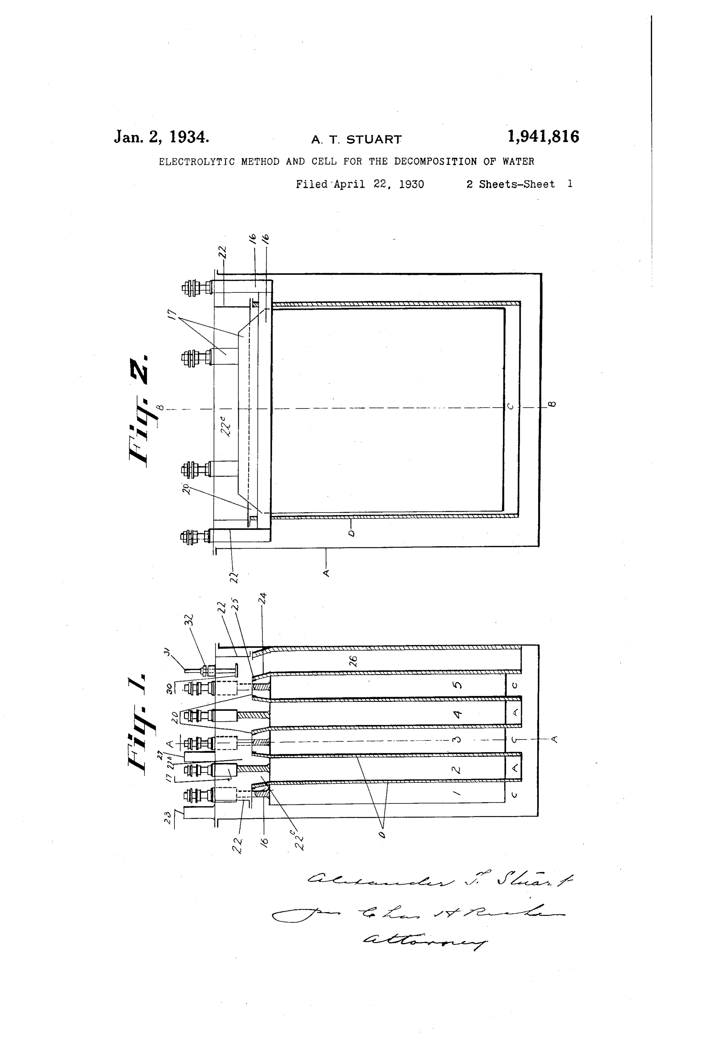
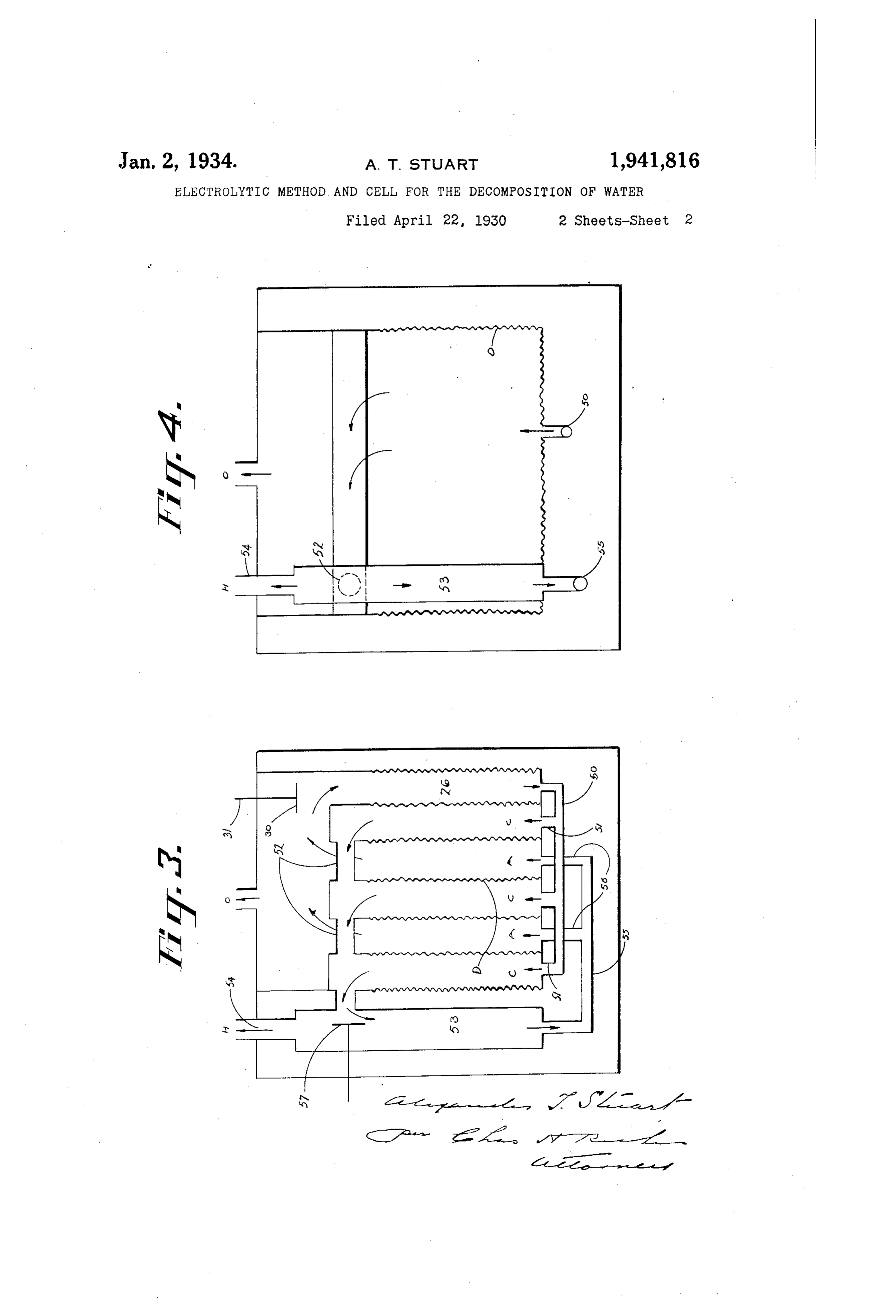
Various imethods and means Imay be devised for bly of the cell the ainodes are positioned betweeni creating and maintaining this cyclic circulation. the cathodes. The strips for?kning the electrodes and intermixing the anolyte and catholyte during are Set edgeWise towards each other with the SULr the cell operation Without departing from the faces of the electrodes in the Same direction aS principle of the invention. One method Which II the circuit of the current acroSS the intervening have satisfactorily employed consistS of provid spaces or electrolytic gaps betWeen the anodes ing separate channels of circulation for the ano and cathodes, and each of these gaps is of a width lyte and catholyte from the top of the anode and approximately equal to the thickness - of the dia cathode compartments, respectively, to the bot phragmS.
0 tom of the cell, and intimately mixing them to Above and overhanging each cathode is a chan 85 Irestore the normal Strength of the electrolyte nelled hood 20, and Secured to the perimeter of before re-entering the several cell compartmentS. the entire group of hoods are four skirts or plates Another method which i have Satisfactorily emi 22 for Suspending the hoods firCYMm the cover 22d, ployed consists of a positive cyclic circuiation of of the Cell. The SkirtS CÍ' plates 22, together 15 the anolyte from the anode compartmentS into With the group of hoods 20, form a header 22C the cathode compartments and the catholyte fr?im above the electrodes. interjacent the hoods 20 the cathode compartmentS into the anode com are openings 22b, located one above each anode, partments, when the gases have been Separated for the circulation of the anolyte and anodic from it, thereby utilizing the enriched electrolyte products into the header. Surrounding each an of one set of compartments for restoring the im ode is a diaphragm D, which is of a tubular 9 5 poverished electrolyte in the other set of compart formation, open at the top and bottom, and ex ments to substantially normal strength through tends from the hoods 20 to beliow the bottom of out the Several cell compartmentS, and Ímaintain the electrodes for separating the anodic and ing the i electrolyte at substantially uniform cathodic products of the eiectrolysis. Each dia Strength throughout the cell. phragEYn is secured to the contiguous walls of two 100 In both of the above methods the speed of the adjacent hoods 20 añd the thickness of the dia circulation may be regulated by valves or damp phraginn corresponds to the width of the electro ers suitably installed in the cyclic system, to con lytic gaps between the anodes and cathodes. The trol the rate of movement of the electrolyte and diaphragms divide the cell into a plurality of al 30 prevent the gas being carried to the bottom of the ternately arranged anode and cathode compart 105 cell during the circulation. iments, A. and C, respectively, and in conjunction For an understanding of the invention refer with the channelled hoods maintains the separa ence is to be had to the following description and tion of the anolyte and catholyte and the anodi? to the accompanying drawings, in which: and cathodic products in their respective com 3 5 Fig. 1 represents a vertical section of an oxygen partments. The Width of each electrolytic gap, 10 hydrogen cell ShoWing a preferred method of elec by corresponding approximately to the thickness trode aSSembly, this Section being taken on the of the diaphragm, permits of the edges of the line B-B, Fig. 2. · anodes and cathodes in the cell assembly being * Fig. 2 is a vertical Section on the line A-A, in contact, or substantially so, with the dia 40 Fig. 1. phragms. The current from the positive pole 5 Figs. 3 and 4 are similar views to Figs. 1 and 2 is distributed uniformly to all the anodes and of a modification of the cell, with the electrodes flows outwardly from the edges of each inter Omitted. posed anode strip and across the electrolytic gaps Like characters of reference refer to like parts to the edges of the corresponding interposed throughout the specification and drawings. cathode strips, from the edges of which it flows 20 The cell comprises a tank A, a plurality of elec inwardly. In this arrangement each strip " of trodes numbered 1 to 5, inclusive, alternately ar each electrode has two active edges forming re ranged as cathodes and anodes, and porous dia acting areas with currents of equal intensity phragms D interposed between them for separat flowing in opposite directions from the edges of 50 ing the oxygen and hydrogen liberated during the each interposed electrode whereby equal quanti decomposition of the electrolyte. Any number of ties of gas are evolved at each edge of each inter electrodes may be used and the general construc posed electrode. The maximum current intens tion and assembly of the electrodes and the inter ity exists at the edges and the minimum cur posed diaphragms hereinafter described and rent intensity, exists interjacent the edges and 55 shown in the accompanying drawings are similar this differential of intensity provides a path be 30 to the electrodes shown and described in my Let tween the edges of each strip for the unimpeded ters Patent of the United States of America and rapid uplift of the electrolyte and gases, and 1,597,553 dated August 24th, 1926, but any other reduces to a negligible amount, the gases in sus type of electrodes and i diaphragms suitable for pension between the electrodes and adhering to oxygen-hydrogen cells i may be employed. the electrodes and diaphragms and tends to pre 35 * Each electrode comprises a current feeder and vent polarization of the cell. , a group of thin, narrow strips, arranged vertically The Oxygen, and anolyte rise to the top of the in Substantially parallel planes, individually sep anode compartments and pass through the open arated, and directly connected collectively with ings 22b into the header 22c formed by the skirts 65 the current feeder. The current feeders 16 of the 22 and channelled hoods, and these skirts and 140 odd numbered electrodes are connected with the hoodse keep the anolyte and oxygen separated negative pole of the current and consequently all from the catholyte and hydrogen. The hoods 20 the odd numbered electrodes are cathodes. The extend lengthwise of the cell and beyond the ends Current feeders 17 of the even numbered elec of the header 22c. The catholyte fills the cathode trodes are connected with the positive pole of the compartments and the upper i part of the cell 145 current and consequently all the even numbered exterior of the header to within a few inches electrodes are anodes. The feeders 16 and 17 are of the cell cover. The cathodic products rise shown to be located above the strips but they may through the cathode compartiments to the hoods be located below the strips at a position which -75 will intercept their vertical axes. In the assem and are conducted by them to the ends of the cell, eXterior of the header, from which they pass, to 150
Page 5
the hydrogen offtake 23. The catholyte circulates cell, and regulating the speed of the circulation upwardly through the cathode compartments to for2.ensuring the offtake of pure gases. An electrolytic cell for the decomposition of the hoods, by which it is deflected to the ends water which comprises a plurality of electrodes of the cell where it filows downwardly to the alternately arranged as anodes - and cathodes, 8( bottom, while the hydrogen separates and col lects under the cell cover. In the bottom of the and dividing porous diaphragms interposed between them header is an opening 24, surrounded by a collar for the cell into a corresponding num 25, from which is suspended an asbestos tube ber of anode and cathode compartments, in com 26 extending to the bottom of the cell. The bination with means within the cell separate 0 anolyte i fills the anode compartments and the from the anode and cathode compartments for , 85 header to within a few inches of the cell cover returning the anolyte and the catholyte from and from the header passes down the tube 26 and the tops of the anode and cathode compartments, mixes with the catholyte below the anode and respectively, to the bottom of the cell and inter cathode - compartments. To control the circula mixing them below the electrodes for maintain : 5 tion of the electrolyte the opening of the header ing the electrolyte º at substantially if the - same 90 may be provided with a valve or damper 30, con strength throughout the cell, and means for structed with a rod or rods 31 extending above the controlling the speed of the circulation through cell cover and fitted with a lock nut or nuts 32 by the cell. W- : : which it is adjusted. By completely closing the 3. An electrolytic cell as claimed in claim - 2 95 20 valve - or damper the cyclic circulation of the having means for the return of the anolyte anolyte can be arrested. By fully opening it a from all the anode compartments, and other rapid circulation may be maintained, and the means for the return of the catholyte from all speed or rapidity of circulation can be regulated Of the cathode compartments to the bottom of between these extremes by the adjustment of the the cell.
25 Valve or damper. 4. An electrolytic cell as claimed in claim 2 100 During the operation of the cell process the having means for the return of the anolyte from current circuiting from the feeders 1 to the an all the anode compartments, and other means odes activates the edges of those electrode Strips for the return of the catholyte from all of the and results in the liberation of oxygen, which rises cathode compartments to the bottom of the cell, 30) through the anode compartmentS and passes into and means for regulating the speed of the circu 105 the header, from Which it escapes through the lation.
oxygen offtake 27. The current circuits out 5. An electrolytic cell for the decomposition of wardly from the edges of the anode strips to Water including a plurality of electrodes alter the edges of the cathode strips, from which it mately arranged as anodes and cathodes, and | 35 circuits in Wardly and paSSes to the feeder 16. porouS diaphragms interposed between them for 110 The hydrogen generated in the cathode compart dividing the cell into a corresponding number of ments passes upwardly to the hoods and is di anode and cathode compartments, in combina rected by them to the ends of the cell, from which tion with means for creating a cyclic circulation it escapes through the hydrogen offtake 23. In of the electrolyte by returning the anolyte and :40 Figs. 3 and 4 a positive circulation of the elec catholyte from the top of the anode and cathode 15 trolyte is maintained by connecting the bottom COmpartments to the bottom of the cell and in- *** Of the tube 26 With a manifold 50, and con termixing them below the electrodes for main necting the manifold with the bottom of each taining the electrolyte at substantially the same cathode compartment by a pipe 51, So that the strength throughout the cell, which comprises a 45 anolyte passing down the tube 26 and through header located above the electrodes in circula- 120 the manifold 50 Will be compelled to pa SS into tion with all the anode compartments, and a duct the cathode compartments C. The tops of the eXtending from the header for the return of the cathode compartments C are connected by pipes anolyte to the bottom of the cell, and means for 52 with a tube 53 provided With a hydrogen off regulating the speed of the circulation for en 50 take 54. The bottom Of the tube 53 is connected Suring the offtake of pure gas. to a manifold 55, which in tUlrn is connected by 6. An electrolytic cell as claimed in claim 5 125 pipes 56 with the anode compartments A and having valves for controlling the flow from the the catholyte is thus compelled to pass into the header through the duct and regulating the anode compartments. Controlling the circulation speed of the circulation of the anolyte. 55 through the pipes 52 is a valve or damper 57 Sim 7. An electrolytic method for the decompo 30 ilar to the Valve or damper 30 for the purpose sition of water in a tank type cell character of regulating the speed of the circulation. By ized by a positive cyclic circulation of the elec closing the dampers and thereby preventing cir trolyte within each cell for maintaining all the Çullation, the voltage of the cell imli mediately rises, electrolyte therein at uniform normal strength 60 with a consequent lowering of the cell efficiency. effected by collecting the electrolyte from the top 135 By opening the damper the circulation is renewed, of the electrode compartments of one polarity; * * the voltage falls to normal, and the cell efficiency maintaining its separation from the electrolyte is restored. of the compartments of the other polarity and Having thus fully described my invention, what returning it to the bottom of the same cell sep I claim as new and desire to Secure by Letters arately from the electrode compartments, mix- 140 Patent is: ing it with the electrolyte from the electrode 1. An electrolytic method for the decomposi compartments of the other polarity and then re tion of water which, in addition to the electroly circulating the mixed electrolyte through the sis and offtake of the gases, comprises a positive electrode compartments.
70 cyclic circulation of the electrolyte within the cell 8. An electrolytic method for the decomposi-145 created by returning the anolyte and catholyte, tion of water in a tank type cell characterized by free of oxygen and hydrogen, from the top a positive cyclic circulation of the electrolyte to the bottom of the cell, intermixing them for within each cell for maintaining all the electrolyte restoring the electrolyte to and maintaining it at therein at uniform normal strength effected by substantially uniform strength throughout the collecting the electrolyte from the top of the 150
Page 6
i electrode i compartments of one polarity; main 10. The electrolytic method for the decompo taining its - Separation from the electrolyte of sition of water as claimed in claim 9 in which the the compartments of the other polarity and re electrolyte from both sets of compartments is re * turning it to the bottom of the same cell to re turned separately to the bottom of the cell 5 circulate therethrough, and regulating the speed through different channels. of-the circulation for ensuring the offtake of pure 11. An electrolytic method for the decompo
sition of water as claimed in claim 9 in which -9. An electrolytic method for the decomposi the Speed of the circulation is regulated to con tion of water which in addition to the electrolysis trol the rate of movement for the return of the 3n - and offtake of the gas comprises a positive cyclic electrolyte from the top to the bottom of the ** circulation of the electrolyte. within each cell cre cell.
cated by collecting all the electrolyte from the top 12. An electrolytic method for the decompo “ of the º electrode compartments of one polarity; sition of water as claimed in claim 7 in which the maintaining -it separate from the electrolyte of Speed of the circulation is regulated for ensur i FF –the compartments of the other polarity, return ing the offtake of pure gases by preventing them - 9 ing it to the bottom of the same cell separately being carried in suspension in the anolyte and *from the electrode i compartments, and utiliz catholyte returning from the anode and cathode ing the enriched electrolyte of one set of com compartments to the bottom of the cell. partments for restoring the impoverished elec trolyte of the other set of compartments to sub ALEXANDER T. STUART. stantially normal strengh throughout the cell.
70 | 345
Provenance
- Collection
- Cited prior art
- Original PDF
- patentimages.storage.googleapis.com →
- Filed
- 1930-04-22
- Pages
- 6
- Method
- pdftotext (the PDF's own text layer) + pdftoppm 300dpi page scans
- Source
- Google Patents bibliographic record
- Granted
- 1934-01-02
- Inventors
- Stuart Alexander Thomas
- Transcribed from
- patentimages.storage.googleapis.com →