patent · US5324398
Capacitive discharge control circuit for use with electrolytic fluid treatment systems
28 June 1994
Page 1 — bibliographic record
United States Patent (19) 11 Patent Number: 5,324,398
Erickson et al. 45 Date of Patent: Jun. 28, 1994 54 CAPACITIVE DISCHARGE CONTROL 4,839,002 6/1989 Pernicket al. ........................ 204/58 CIRCUIT FOR USE WITH ELECTROLYTIC 4,917,782 4/1990 Davies ................................. 204/152 UDTREATME 4,937,557 6/1990 Tucci et al. ......................... 340/603 FL A NT SYSTEMS 4,986,906 1/1991 Dadisman ........................... 204/169 75 Inventors: Robert K. Erickson, Belmont; 5,055,170 10/1991 Saito .................................... 204/228 Francois X. Prinz, San Jose, both of 5,057,212 10/1991 Burrows ................................ 210/85 Calif. 5,062,940 l/1991 Davies ................................. 204/228 73 Assignee: Water Regeneration Systems, Inc., FOREIGN PATENT DOCUMENTS Belmont, Calif. 0329562 8/1989 European Pat. Off. . 21) Appl. No.: 901,411 203896 11/1983 Fed. Rep. of Germany . 22 Filed: Jun. 19, 1992 Primary Examiner-John Niebling Assistant Examiner-Arun S. Phasge 51 int. Cl. .............................................. C02F1/61. Attorney, Agent, or Firm-Christensen, O'Connor, 52 U.S. C. .................................... 204/149; 204/152; Johnson & Kindness
58 Field of Search ............... 204/149,152,228,305, 57) ABSTRACT 204/400, 406, 412 An electrolytic filter system (16) is disclosed for use in (56) References Cited treating fluid provided by a fluid source (12) to a sup
plied environment (14). The system includes an electro lytic cell (18), whose operation is governed by a control 3,519,550 7/1970 Winslow et al. . ... 204/305 circuit (20) to allow a desired average current to be 3,532,614 10/1970 Shirley ......... 204/19 applied to the cell substantially independent of varia 3,679,556 9/1968 Doevenspeck ... 204/269 tions in fluid resistivity, to allow the cell to simulta 3,865,710 2/1975 Phipps ............ ... 204/228 neously achieve, for example, the desired removal of 4,119,520 10/1978 Paschakarnis et al. ... 204/276 contaminants, killing of biological materials, and alter 4,263,114 4/1981 Shindell ............... .26/145 9. - .O
ation of the fluid's chemical characteristics, and to pro vide relatively high levels of energy to the fluid quickly 4,419,206 12/i983 Frame .................. ... 20/228 and efficiently.
4,629,992 12/1986 Nudelmont .......... ... 324/.464 4,734,176 3/1988 Zemba, Jr. et al. ................ 204/49 27 Claims, 6 Drawing Sheets
FROM FLUID
SOURCE 12
TO SUPPLIED
ENVIRONMENT 1 ?t
CURRENT
SENSOR
CAPACTIVE I
STORACE
CIRCUIT
POWER
SWITCHING
CIRCUIT
INVERTER CONTROLLER
CONTROL CIRCUIT
TO ELECTROLYTIC
CELL 18
Page 2
Drawing sheet — no readable text.
Page 3
Drawing sheet — no readable text.
Page 4
Drawing sheet — no readable text.
Page 5
Drawing sheet — no readable text.
Page 6
Drawing sheet — no readable text.
Page 7
VOLTACE V2
AVERACE
CURREN
FIG. 6. TIME I
VOLTACE v. AVERACE
CURRENT
FIC. 7. TIME I
VOLTACE v. AVERACE
CURRENT
FIC. 8. TIME I
VOLTACE V N-H N-N-N-N-H. AVERACE
CURRENT
FIG. 9. TIME 2
V, M - -va- asesea-aesa-a-au-uru-o-o-operParadar-bodbar-P CURRENT VOLTACE AVERACE
FIC. 1 O. I
Page 8
rather than being used to treat water, making the cir
CAPACTIVE DESCHARGE CONTROL CIRCUIT cuits relatively inefficient. In addition, the Grundler and FOR USE WITH ELECTROLYTICFLUID Dadisman circuits are both relatively complex. TREATMENT SYSTEMS An alternative method of handling variations in water resistivity is to provide an electronic control
FIELD OF THE INVENTION circuit that allows water purification and ion generation This invention relates to electrolytic fluid treatment systems to maintain constant current flows, substan systems and, more particularly, to circuits for use in tially independent of variations in water resistivity. In controlling such systems. that regard, U.S. Pat. No. 4,119,520 (Paschakarnis et al.) O discloses a water purification unit that includes such a
BACKGROUND OF THE INVENTION current control circuit. The current to be controlled Electrolytic fluid treatment systems are widely used flows through a resistor, as well as between the elec to, for example, remove impurities and contaminants trodes. A differential amplifier and transistor coopera from fluids. In such systems, the fluid to be treated is 15 tively control the current by keeping the voltage drop passed between one or more pairs of electrodes. An across the resistor equal to the reference potential electric potential applied to the electrodes establishes an across a diode. As a result, the current flowing between electric current between the electrodes. As a result, the electrodes is kept constant.
impurities in the fluid migrate and adhere to the elec Similarly, U.S. Pat. No. 5,055,170 (Saito) discloses an trodes, biological materials in the fluid are killed, and 20 ionic water generator that accounts for variations in the fluid's chemical composition may be altered. water resistivity. In that regard, the system employs a One fluid that is commonly processed by electrolytic central processing unit that calculates the appropriate fluid treatment systems is water. The electrolytic treat voltage to be applied to the electrodes for the water ment of water is, however, complicated by the widely being processed. This voltage is computed by multiply varying water characteristics encountered from one ing some voltage corresponding to the desired ion con water source to another. In that regard, the resistivity of 25 centration by a factor equal to the resistance of the water, which is inversely proportional to conductivity, water actually being processed divided by the resis commonly varies over a range extending from 30 to tance of some reference water. 1400 ohm-meter. Such resistivity variations may signifi As will be appreciated, the Paschakarnis et al. and cantly alter the performance of an electrolytic filter Saito systems exhibit several shortcomings. First, the system. 30
More particularly, the interelectrode resistance is control circuits of both systems are relatively complex. Because the Paschakarnis et al. circuit introduces an dependent upon the resistivity of the water flowing additional resistance into the current path, it is also between the electrodes. With a fixed electric potential relatively inefficient.
applied to the electrodes, current flow between the vantageously requiresThe Saito circuit, in turn, disad electrodes will vary in inverse proportion to the water's 35 made for subsequent usereference
measurements to be controlling the voltage ap resistance. If water resistivity is relatively high, the current may be too low to achieve the desired treatment plied to the electrodes.
Another circuit for controlling an ion generator in a of the water. On the other hand, if water resistivity is relatively low, the current may be so high as to damage water purification system is disclosed in U.S. Pat. No. or otherwise decrease the life of system components. 4,734,176 (Zemba, Jr.). The circuit controls the duty A variety of different systems have been developed cycle of energy applied to the generator to achieve the that attempt to accommodate such variations in water desired level of purification for various applications and resistivity. For example, circuits have been developed water conditions. In that regard, an operator apparently to expose water purification and ion generation systems evaluates water conditions and then manually adjusts the control circuit to effect a desired change in duty to relatively constant load resistances, regardless of 45 cycle.
variations in water resistivity. In that regard, U.S. Pat.
No. 4,769,119 (Grundler) discloses a water ionizing Like the other circuits described above, the Zemba, device that includes several electrodes. If the resistivity Jr. arrangement has certain limitations. For example, of the water being ionized is relatively low, a relatively the ability of the Zemba, Jr. circuit to handle variations high resistance is introduced in series with the elec in water resistivity is not discussed and is uncertain. trodes. On the other hand, if the water's resistivity is Also, because the circuit does not automatically re relatively high, a relatively low resistance is introduced spond to changing water conditions, it may fail to in series with the electrodes. In either case, by keeping achieve the desired regulation in many instances. the system's total resistive load constant, a constant Turning now to another problem experienced in the current flow is maintained between the electrodes. 55 electrolytic treatment of fluids, conventional electro U.S. Pat. No. 4,986,906 (Dadisman) describes another lytic fluid treatment systems typically do not perform variation of this approach. The Dadisman water purifi equally well in removing impurities, killing biological cation system includes a constant current control circuit materials, and altering the fluid's chemical composition. in which changes in water resistance cause opposing At best, existing systems achieve one of the desired changes in the effective resistance of a field-effect tran objectives relatively well, while exhibiting compro sistor (FET) included in the circuit. These changes in mised performance with respect to the other objectives, FET resistance offset the changes in water resistance, More particularly, most such systems fail even to differ allowing the current to be kept substantially constant. entiate between these various objectives, much less Unfortunately, the approaches taken by Grundler achieve them fully and simultaneously.
and Dadisman have certain limitations. In that regard, One final problem encountered in the electrolytic the Grundler and Dadisman circuits both increase cir treatment of fluids is the limited ability of conventional cuit resistance to offset decreases in water resistance. As systems to provide large quantities of energy to the fluid a result, energy is dissipated in circuit components over brief intervals in an efficient manner. For example,
Page 9
while some systems may be suitable for passing rela- . In accordance with yet another aspect of the inven tively low currents through the fluid during short inter tion, an electrolytic fluid treatment system is disclosed. vals, they are typically unable to apply higher currents The system includes at least one pair of electrodes defin to the fluid. Alternatively, while some systems are able ing a water flow path therebetween. A capacitor is to provide high currents to the fluid quickly, they are 5 included for storing electrical energy for delivery to the relatively inefficient. pair of electrodes. A switching circuit is included for In view of these observations, it would be desirable to causing energy stored by the capacitor to be delivered provide a control circuit suitable for controlling the to the pair of electrodes as a plurality of current pulses. operation of an electrolytic fluid treatment system sub If the system is further suitable for treating fluids of stantially independent of variations in the resistivity of 10 varying resistivity, an ammeter is included for produc fluid treated by the system. It would also be desirable to ing an output representative of the current pulses deliv provide a control circuit that allows several aspects of ered to the pair of electrodes. A control circuit is then the system's performance to be optimized, without also included for controlling the switching circuit in undue circuit complexity, inefficiency, or operator in response to the output of the ammeter. tervention and that is able to provide relatively large 15 In accordance with one additional aspect of the in quantities of energy to the fluid quickly and efficiently. vention, a method and system for electrolytically filter SUMMARY OF THE INVENTION ing water are disclosed. In that regard, water is passed between at least one pair of electrodes. A varying volt
A method is described for controlling the operation age is also applied across the electrodes to effect the of an electrolytic system used in the treatment of a fluid 20 desired filtering of the water. The method and system exhibiting a potentially variable characteristic. The may be, more particularly, for treating several aspects method includes the steps of producing a plurality of of the water and the varying voltage may include a pulses of electrical energy for application to the electro range selected to treat the several aspects. lytic system. The pulses exhibit parameters including a pulse repetition rate, pulse duration, and pulse ampli- 25 BRIEF DESCRIPTION OF THE DRAWINGS tude. The method also includes the step of evaluating The foregoing aspects and many of the attendant the potentially variable characteristic of the fluid. The advantages of this invention will become more readily method further includes the step of controlling one of appreciated as the same becomes better understood by the parameters exhibited by the plurality of pulses in reference to the following detailed description, when response to the evaluation of the potentially variable 30 taken in conjunction with the accompanying drawings, characteristic of the fluid. wherein:
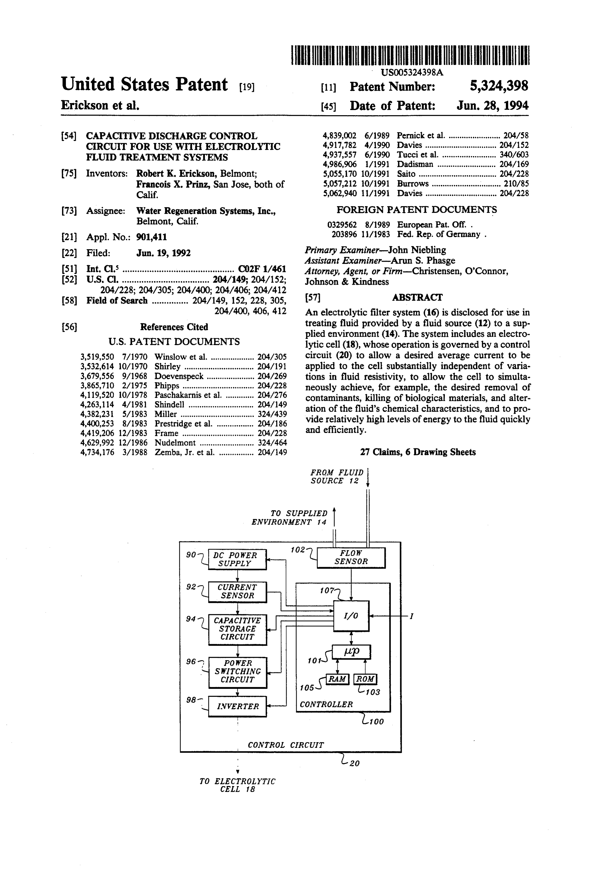
In accordance with another aspect of the invention, a FIG. 1 is a block diagram of a fluid system employing method is disclosed for electrolytically treating water. an electrolytic filter constructed in accordance with the The method includes the step of positioning the water present invention;
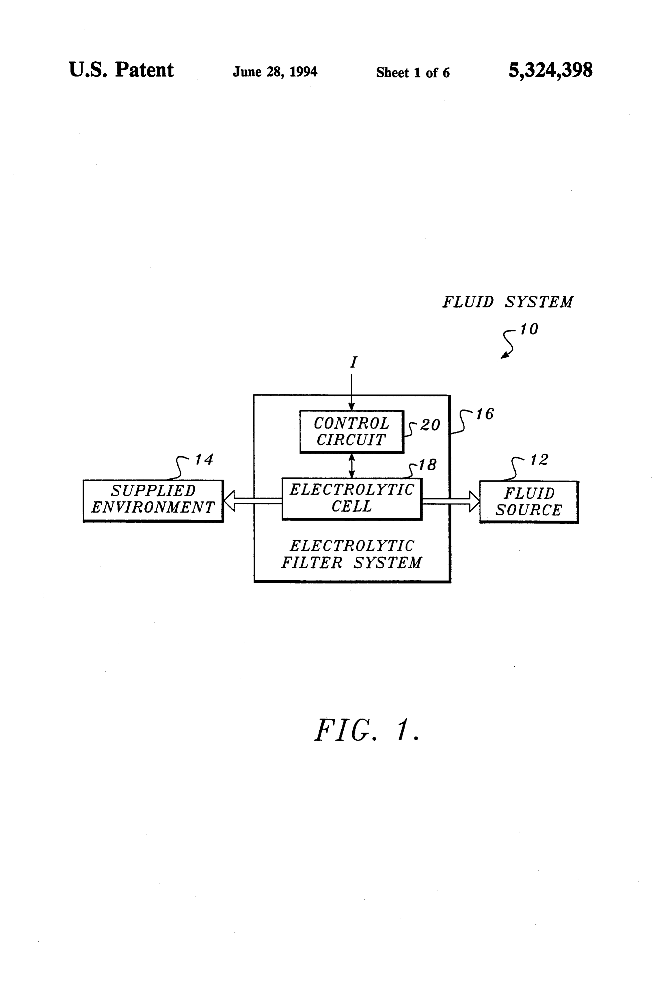
between at least one pair of electrodes. The method also 35 FIG. 2 is an illustration of an electrolytic cell in includes the step of producing a voltage across a capaci cluded in the filter of FIG. 1;
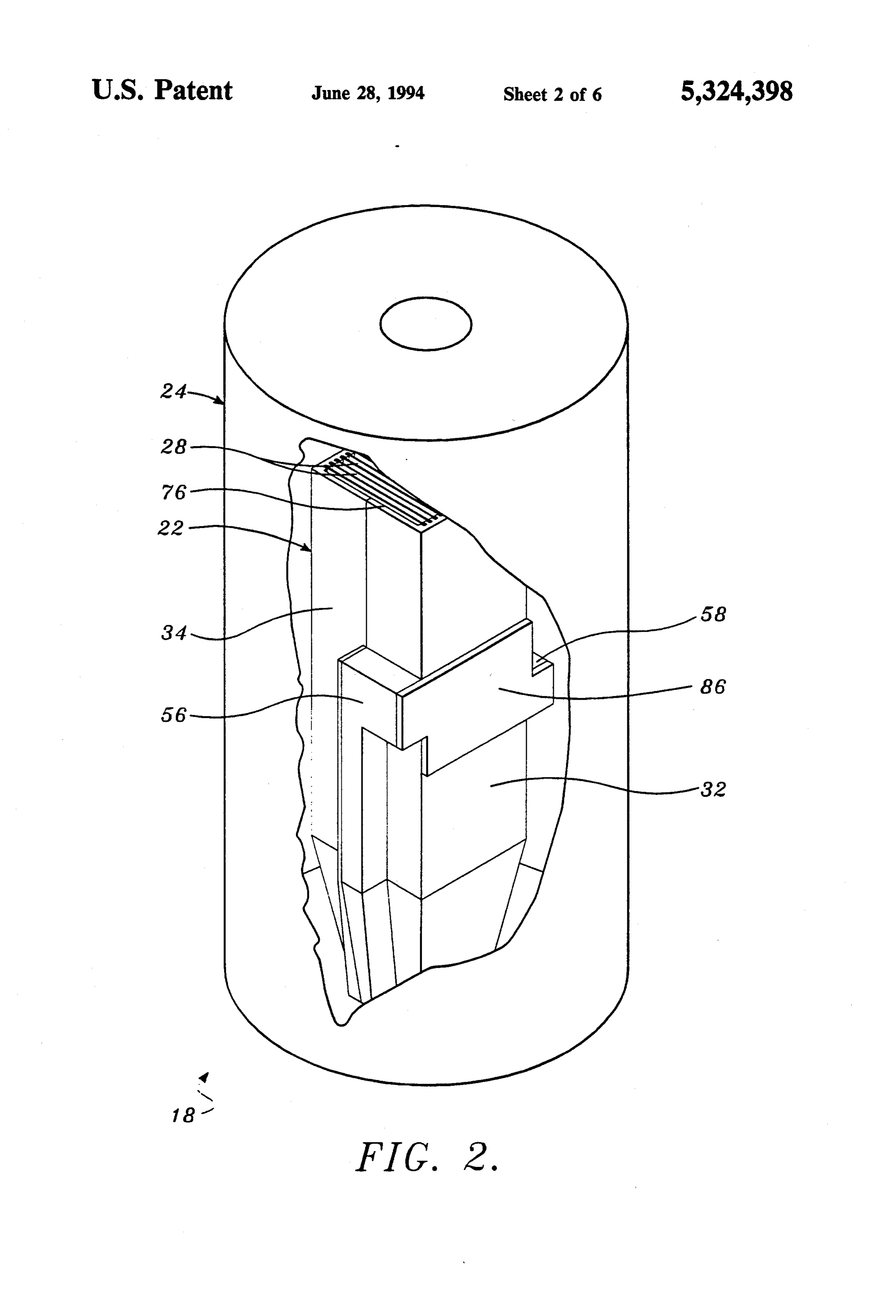
tor and selectively coupling the capacitor to the elec FIG. 3 is a top perspective of an electrode assembly trodes, causing the voltage across the capacitor to included in the cell of FIG. 2, with parts shown in decay and a current to flow through the water between exploded relationship;
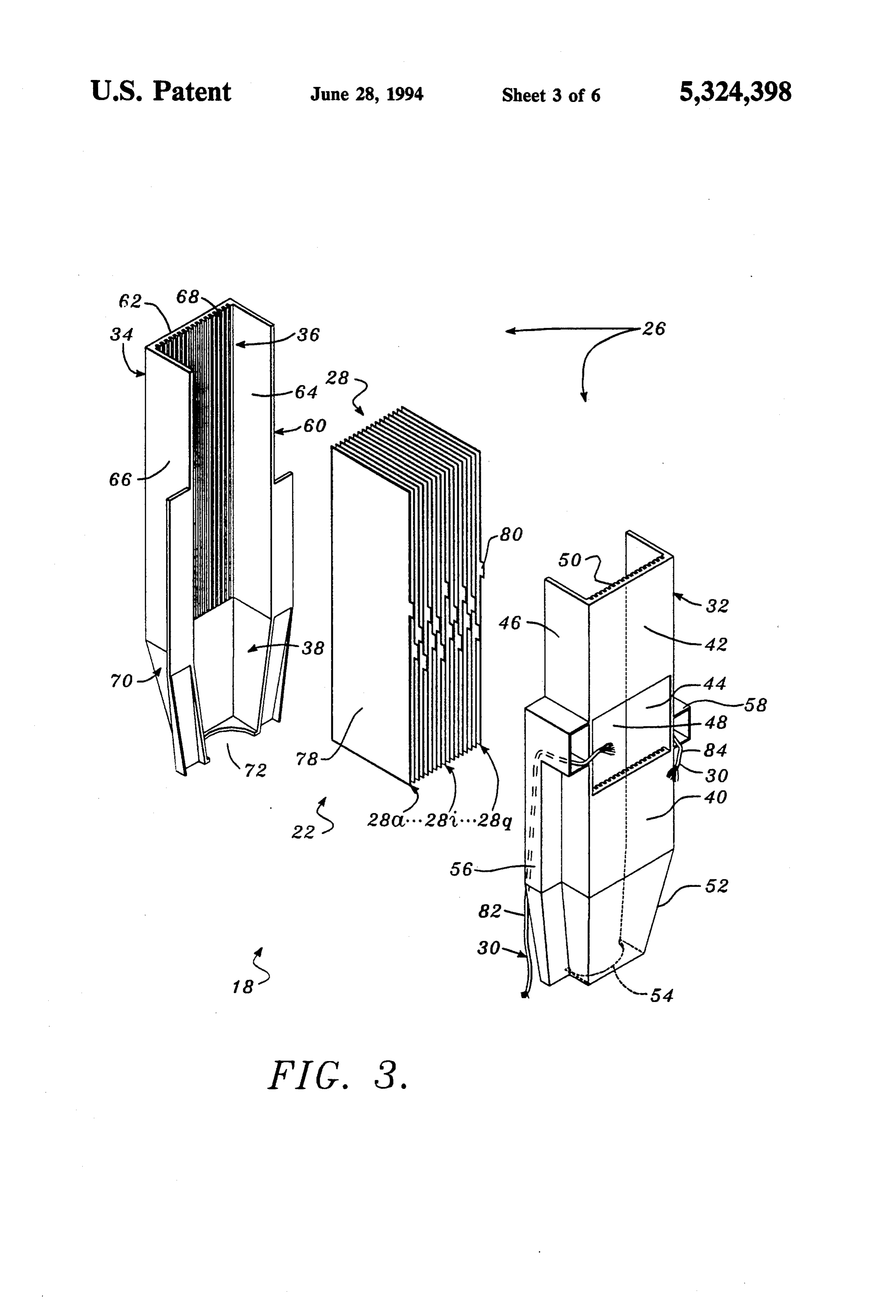
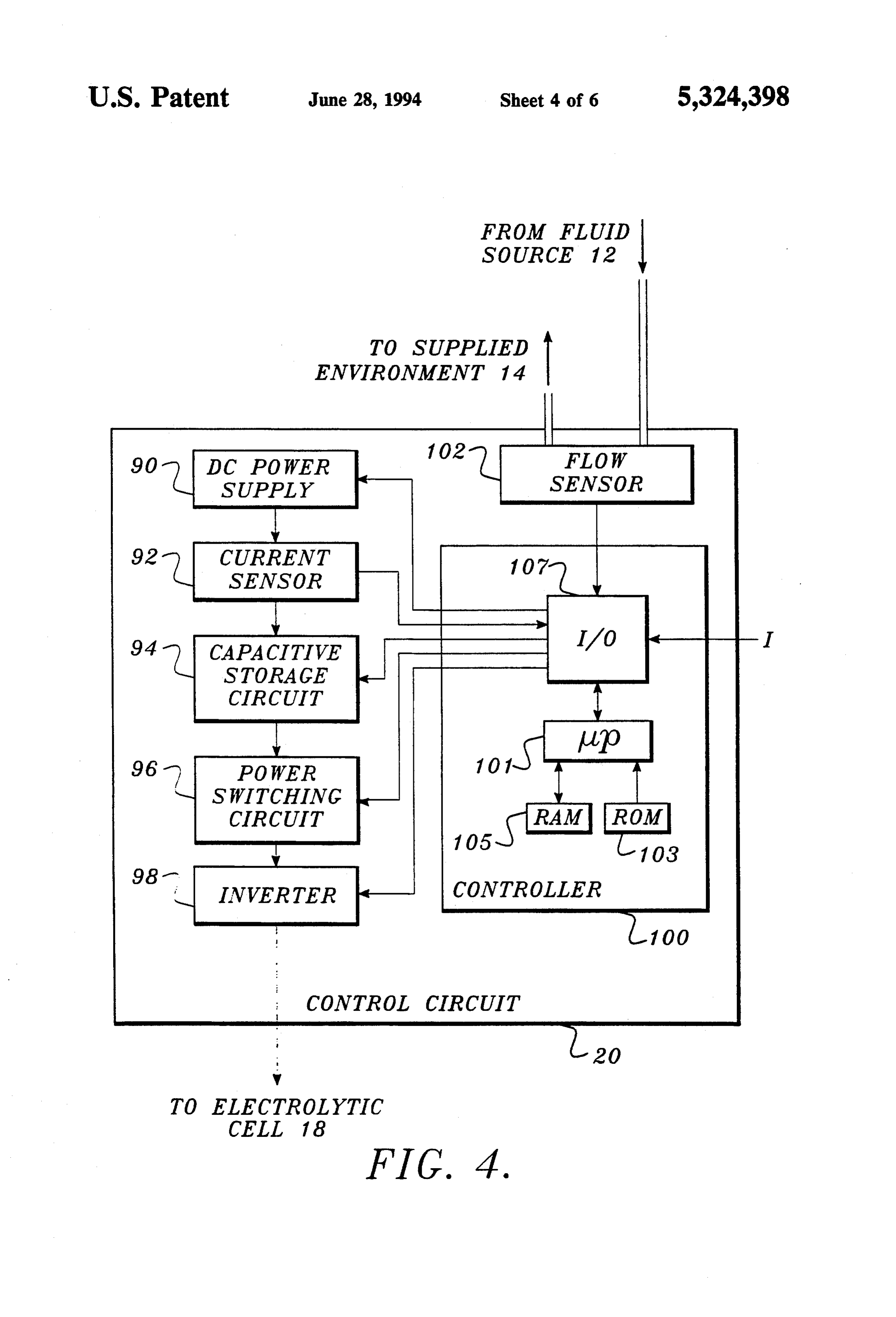
the at least one pair of electrodes. FIG. 4 is a block diagram of a control circuit included The method may be further for electrolytically treat in the filter of FIG. 1;
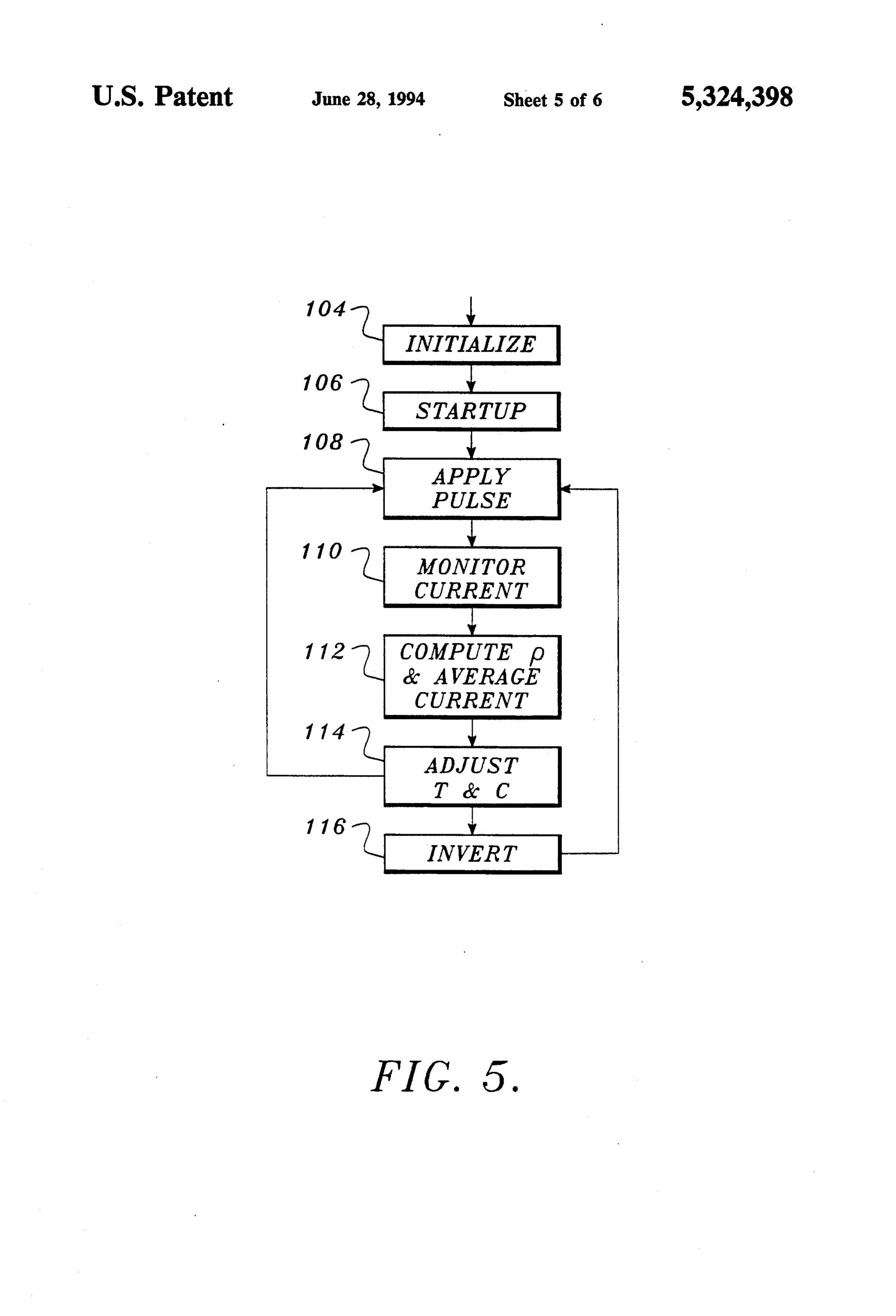
ing the water in a manner that is relatively independent FIG. 5 is a flow chart depicting the operation of the of variations in the electrical resistivity of the water. control circuit of FIG. 4;
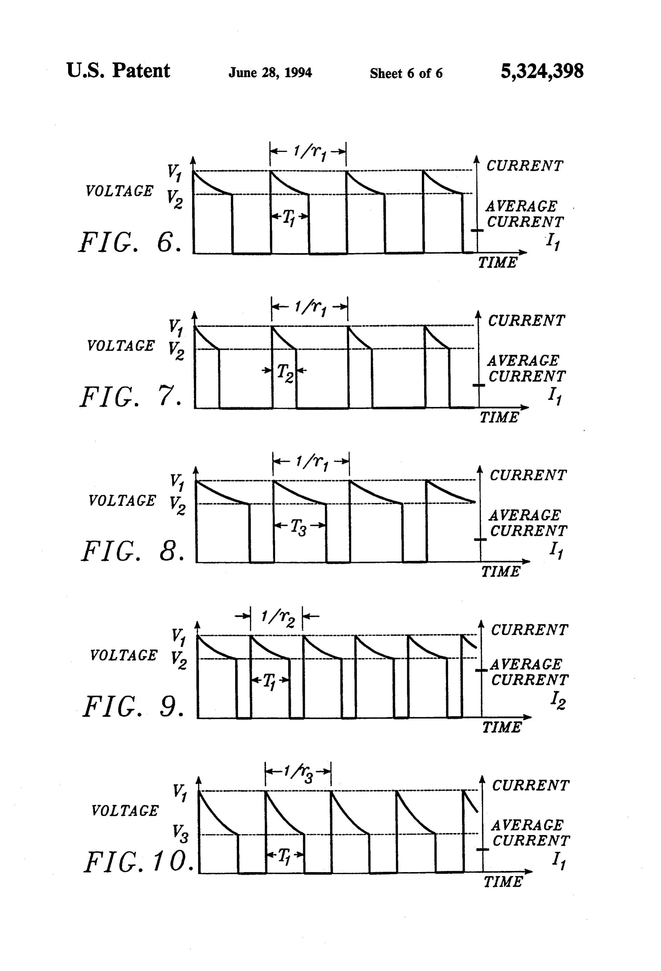
Thus, the method further includes the steps of sensing FIG. 6 is a graph illustrating the output pulses pro the resistivity of the water and selectively disconnect 45 duced by the control circuit of FIG. 4 when the fluid ing the capacitor from the electrodes when the voltage being treated has some initial resistivity; across the capacitor decays to a pre-determined thresh FIG. 7 is a graph illustrating the output pulses pro old. The steps of selectively coupling and selectively duced by the control circuit of FIG. 4 when the resistiv disconnecting are repeated at a predetermined repeti ity of the fluid being treated is below the initial resistiv tion rate and are separated by an interval of time whose 50 ity;
length is dependent upon the sensed resistivity of the FIG. 8 is a graph illustrating the output pulses pro Water. duced by the control circuit of FIG. 4 when the resistiv In accordance with another aspect of the invention, a ity of the fluid being treated is above the initial resistiv circuit is disclosed for providing a desired electric cur ity;
rent to the electrodes of an electrolytic fluid treatment 55 FIG. 9 is a graph illustrating the output pulses pro system, substantially independent of variations in the duced by the control circuit of FIG. 4 when the average fluid passed between the electrodes and treated by the current applied to the electrolytic cell is to be increased; system. The circuit includes a sensor for sensing varia and tions in the fluid passed between the electrodes. The FIG. 10 is a graph illustrating the output pulses pro circuit also includes a delivery device for delivering a duced by the control circuit of FIG. 4 when the range plurality of electric current pulses to the electrodes, the of voltages applied to the electrolytic cell is to be in electric current pulses exhibiting a pulse duration, pulse creased.
repetition rate, and pulse amplitude. Finally, a control DETAILED DESCRIPTION OF THE circuit, responsive to the sensor, is included for control PREFERRED EMBODIMENT ling the delivery device to ensure that the desired elec 65 tric current provided to the electrodes remains substan Referring now to FIG. 1, a fluid system 10 con tially independent of variations in the fluid passed be structed in accordance with the invention is shown. tween the electrodes. Fluid system 10 includes a fluid source 12 that provides
Page 10
fluid to a supplied environment 14 via an electrolytic ner. To that end, the fluid source 12 may include, for fluid treatment system, such as filter system 16. As will example, a pump and various valves. be described in greater detail below, the electrolytic One common example of a fluid source 12 is a munici filter system 16 is designed to operate in a manner that pal water supply. As will be appreciated, the water is not adversely impacted by variations in the fluid's available from many such supplies may exhibit widely resistivity and that is equally effective in removing in varying characteristics. For example, it is not uncom purities, killing biological materials, and altering the mon for the resistivity of water from different munici chemical composition of the fluid. The system 16 also palities to range between 30 to 1400 ohm-meter. allows relatively high energy levels to be applied to the Like the fluid source 12, supplied environment 14 fluid quickly and efficiently. O may take a variety of different forms. Examples of sup Before discussing the construction and operation of plied environments 14 include swimming pools, water system 10 in greater detail, the physics involved will be heaters, and drinking water dispensers. In some in briefly reviewed. In that regard, conventional electro stances, although not shown in FIG. 1, the supplied lytic filter systems pass electric current between at least environment 14 may use the fluid and return it to the one pair of electrodes to effect the desired filtration of 15 source 12 for treatment. In other instances, the supplied fluids located between the electrodes. The ability of the system to cause impurities to migrate to the electrodes, environment of the fluid.
14 may represent the ultimate destination kill biological material, and alter the chemical composi The heart of fluid system 10 is the electrolytic filter tion of the fluids depends, in part, upon the magnitude system 16. As indicated in FIG. 1, filter system 16 in of the current flow between the electrodes. . 20
Assuming that a fixed voltage V is applied across two cludes an electrolytic cell 18 and control circuit 20. As electrodes, the magnitude of the current I flowing be will be described in greater detail below, the electro tween the electrodes varies substantially in accordance lytic cell 18 processes fluid flowing from source 12 to with the expression: the supplied environment 14. The control circuit 20 25 provides electrical energy to the cell 18 in a controlled
Is VR (l) fashion, allowing cell 18 to effect the desired filtration of the fluid substantially independent of variations in where R is the resistance of the fluid between the elec fluid resistivity.
trodes. The resistance R of the fluid can be determined Reviewing these two primary components of filter in accordance with the expression: 30 system 16 in greater detail, as shown in FIG. 2, the electrolytic cell 18 includes an electrode assembly 22
R=pL/A (2) positioned within a reservoir 24. The electrode assem where p is the resistivity of the fluid, L is the separation bly 22, which is shown in greater detail in FIG. 3, in cludes as its primary components a housing 26, a plural of the two electrodes, and A is the cross-sectional area ity of electrodes 28, and electrical wiring 30. The hous of the fluid path between the electrodes. The resistivity 35 ing includes a first section 32 and second section 34, p, in turn, varies in accordance with the expression: which cooperatively define an electrode chamber 36 p=pol +a(T-To)) (3) and inlet chamber 38 therebetween.
Addressing the construction of the first section 32 of where pois the resistivity of the fluid at some tempera housing 26 in greater detail, the portion of the first ture To, T is the actual temperature of the fluid, and a section 32 that defines the electrode chamber 36 in is a temperature coefficient. As a result, the resistivity cludes a channel piece 40 formed by a panel 42 and sides and, hence, resistance of the fluid defining the current 44 and 46. A rectangular opening 48 is provided in panel path between electrodes changes in response to both 42, midway between its two ends, and a plurality of fluid and temperature fluctuations. 45 longitudinally extending, electrode retention grooves As will be appreciated from equation (1), with a fixed 50 are provided on the inside of panel 42. The first voltage applied between the two electrodes, the magni section 32 also includes an inlet piece 52, which extends tude of the current I flowing therebetween depends from the channel piece 40 and exhibits a tapered cross upon the fluid resistance R. The resistivity p (and its section. A semicircular opening 54 is provided at the reciprocal, conductivity o) of the fluid may vary con 50 end of inlet piece 52 to form one-half of a fluid inlet. siderably with time, due to differences in the composi Roughly L-shaped wiring conduits 56 and 58 are tion of the fluid as well as its temperature. Such changes provided on the sides of the first section 32 of housing alter the interelectrode resistance Rand, hence, current 26. As illustrated in FIG. 3, conduits 56 and 58 are I and potentially impact the filter's effectiveness. substantially rectangular in cross section and include As will be described in greater below, if energy is 55 openings positioned adjacent the opening 48 in panel 42. applied to the electrodes in the form of a plurality of These openings are provided in a longitudinally stag pulses, some of the characteristics of the pulses can be gered configuration that allows the electrical wiring 30 controlled in response to variations in fluid resistivity to received within the conduits to be attached to the vari maintain a relatively constant average current flow ous electrodes in a relatively streamlined fashion de between the electrodes. The electrolytic filter system 16 scribed in greater detail below. The conduits 56 and 58 described below maintains the desired current in this extend axially along the open side of first section 32, ae. terminating in openings adjacent the end of inlet piece Addressing now the construction of the various com 52. The electrical wiring 30 extends from these open ponents of system 10 individually, the fluid source 12 ings to the control circuit 20.
may take any of a variety of forms. Typically, the fluid 65 The second section 34 of housing 26 mirrors the first source 12 will include a fluid supply or reservoir, as section 32, with the exceptions that the opening 48 and well as some arrangement for providing fluid to the conduits 56 and 58 are eliminated. In that regard, the filter system 16 in a controllable and pressurized man second section 34 includes a channel piece 60 having a
Page 11
panel 62 and two sides 64 and 66. A plurality of elec (not shown), the electrodes 28 are retained in slots 50 trode retention grooves 68 are provided on the inside of and 68 and the tabs 80 on the various electrodes 28 panel 62 for receiving the electrodes 28. A tapered inlet project from the opening 48 in housing 26, allowing piece 70 extends from the channel piece 60 and includes electrical connections to be made thereto. In that re a semicircular opening 72, which, in cooperation with gard, the electrical cables 30 are separately identified in opening 54, defines a fluid inlet. FIG. 3 as cables 82 and 84. Cable 82 is a standard wire As will be appreciated, the relative size, shape, con cable positioned within wiring conduit 56 and has one struction and materials of the housing 26 can be altered end connected to the connection tabs 80 of electrodes as desired. In the currently preferred arrangement, 28a, 28c, 28e, 28g, 28i, 28k, 28m, 28o, and 28g by, for however, housing 26 is generally rectangular in cross 10 example, soldering or fastening hardware (not shown). section and defines an electrode chamber 36 that is The other end of cable 82 terminates at the control roughly 20.5 centimeters by 5.4 centimeters by 5.1 cen circuit 20. Similarly, cable 84 is a standard wire cable timeters. The electrode retention grooves 50 and 68 are received within wiring conduit 58. One end of cable 84 roughly 0.06 centimeters wide, spaced apart by a dis is coupled to the connection tabs 80 of electrodes 28b, tance of roughly 0.2 centimeters and may extend the full 15 28d, 28f, 28h, 28i, 28.l., 28n, and 28p and the other end length of the electrode plates or be shorter and spaced terminates at the control circuit 20. apart to support the electrode plates at several points. Once the housing sections 32 and 36 have been fas The inlet chamber 38 is roughly 8.1 centimeters long tened together and the appropriate connections made and tapers to a cross section of roughly 4.8 centimeters between cables 82 and 84 and the various electrodes 28, by 4.5 centimeters. When the first section 32 and second 20 the connection tabs 80, electrical connections between section 34 are joined, the semicircular openings 54 and cables and tabs, and the opening 48 are enclosed by an 72 define a fluid inlet 74 of roughly 9.2 square centime encapsulant, such as an epoxy. As a result, the electrical ters. Similarly, the open upper end of housing 26, de connections are insulated from one another and pro fined by the first section 32 and second section 34 pro tected from environmental contaminants. Further, by vides a square fluid outlet 76 of roughly 25.8 square 25 closing the opening 48, fluid flow through the electrode centimeters. Sections 32 and 34 are preferably molded assembly 22 is confined to a path traversing substan from a fluid impervious plastic, such as polyethylene tially the full length of the spaced-apart electrodes 28. terephthalate glycol (PETG). As noted previously, the electrode assembly 22 is Having reviewed the construction of housing 26, the positioned in, and axially aligned with, reservoir 24. construction of electrodes 28 will now be considered in 30 The reservoir 24 is employed to store fluid processed by greater detail. As shown in FIG.3, seventeen electrodes the electrode assembly 22 before it is provided to the 28 are preferably employed. Each electrode 28 includes supplied environment 14. The reservoir 24 may, for a substantially rectangular body 78 that is positioned example, be a roughly cylindrical structure made of a within housing 26 to contact the fluid to be filtered. A fluid impervious plastic such as spun fiber glass (rein connection tab 80, aligned in the same plane as elec 35 forced), acrylonitrite butadiene styrene (ABS). The trode body 78, projects from one edge of the electrode reservoir 24 preferably is roughly 0.6 centimeters thick, body 78. As will be described in greater detail below, 100 centimeters long and 40.6 centimeters in diameter. the connection tabs 80 are designed to extend through The fluid inlet 74 of electrode assembly 22 extends opening 48 in the first section 32 of housing 26 to allow through the base of reservoir 24, defining a fluid inlet electrical connections to be made to the electrodes 28. into reservoir 24. A fluid outlet 88 is provided in the top The electrodes 28 are preferably made of an electri of reservoir 24. As will be appreciated, the reservoir cally conductive fluid impervious material such as a may be equipped with a removable cover, in which the ceramic. The electrode body 78 is roughly 20.3 centi outlet 88 would be provided, allowing access to the meters by 6.0 centimeters by 0.06 centimeters. Connec electrode assembly 22.
tion tab 80 is, for example, roughly 0.6 centimeters by 45 Having reviewed the basic construction of electro 0.5 centimeters by 0.06 centimeters. As shown in FIG. lytic cell 18, a more detailed discussion of the control 3, the location of the connection tab 80 between the two circuit 20 will now be provided. As shown in FIG. 4, a ends of the electrode body 78 varies from electrode to first embodiment of the control circuit 20 includes, for electrode. example, a DC power supply 90, current sensor 92, In that regard, the electrodes 28 are separately desig 50 capacitive storage circuit 94, power switching circuit nated 28a through 28q in FIG. 3. The tabs 80 on elec 96, inverter 98, controller 100, and flow sensor 102. trodes 28a, 28b, 28f, 28i, 28, 28n, and 28g are all spaced Reviewing these components of control circuit 20 roughly 8.3 centimeters from one end of their respective individually, the DC power supply 90 may be of any electrode bodies 78, with the orientation of electrodes conventional design and provides energy for use by the 28a, 28i, and 28g being reversed from that of electrodes 55 electrolytic cell 18 in achieving the desired treatment of 28b, 28f, 28i, and 28n. The tabs 80 on electrodes 28c, the fluid. As shown in FIG. 4, the power supply 90 28g, 28k, and 28o are spaced midway between the two receives inputs from controller 100, allowing the man ends of their respective electrode bodies 78. Finally, the ner in which energy is output by supply 90 to be con tabs 80 on the remaining electrodes 28d, 28e, 28h, 28l, trolled.
28m, and 28p are spaced roughly 9.2 centimeters from In a preferred embodiment, power supply 90 includes one end of their respective electrode bodies 78, with the a transformer for converting a source of AC input volt orientation of electrodes 28d, 28h, 28l, and 28p being age from one level to another, for example, reduced reversed from that of electrodes 28e and 28m. As shown level. A rectifier circuit may also be included to convert in FIG. 3, the varied location of the electrode tabs 80 the transformed AC voltage to a suitable DC voltage. effects a staggered alignment that makes it easier to 65 Finally, a regulation and filtration circuit may be in provide electrical connections to the electrodes 28. cluded to ensure that the rectified voltage, available With the first section 32 and second section 34 of between positive and negative output terminals of sup housing 26 secured together by epoxy or other fasteners ply 90, has the desired DC characteristics.
Page 12
9 O
The current sensor 92 is employed to measure the connecting the two groups as anodes and cathodes, to . current drawn from supply 90. Although the location of increase electrode life. Although the inverter may take the current sensor 92 within the control circuit 20 may any of a variety of forms, in the preferred arrangement, be altered, in the preferred arrangement the sensor 92 is the inverter is a relay.
coupled between the positive or negative output termi As will be appreciated from the preceding discussion, nal of supply 90 and the capacitive storage circuit 94. the controller 100 is employed to regulate the operation The current sensor 92 may be, for example, an ammeter of a variety of different components of the control cir capable of producing outputs representative of currents cuit 20. In one embodiment, the controller 100 includes ranging from one to thirty amperes. The output of cur a microprocessor 101, read only memory (ROM) 103 rent sensor 92 is provided to the controller 100. O for storing program instructions to be executed by mi The capacitive storage circuit 94 is employed to store croprocessor 101 random access memory (RAM) 105 energy from power supply 90, prior to delivering it to for storing data electrolytic cell 18. As will be discussed in greater detail suitable interfacesprocessed by microprocessor 101, and below, the use of the capacitive storage circuit 94 ad to communicate with the remainingmicroprocessor 107 for allowing components of the
vantageously allows relatively high levels of energy to 15 control circuit 20. Each of these components is of con be applied to the fluid over brief intervals and in an ventional design.
efficient manner. Although the storage circuit 94 may The flow sensor 102 is employed to monitor the flow include a single capacitor connected across the positive and negative output terminals of power supply 90, in the of fluid between the fluid source 12 and the supplied preferred arrangement, a plurality of electrolytic capac environment 14. In that regard, the flow sensor 102 may itors are employed and can be selectively connected in be positioned in fluid source 12, supplied environment parallel in response to inputs from the controller 100. As 14, or anywhere in between, but is functionally illus a result, the capacitive storage circuit 94 may exhibit a trated as part of the control circuit 20 in FIG. 4. Al variable capacitance of 10,000 to 100,000 micro Farads. though a variety of different constructions may be em The energy delivered to the electrolytic cell 18 from 25 ployed, in the preferred arrangement, the flow sensor the capacitive storage circuit 94 exhibits an exponential 12 is a flow switch.
decay expressed in the following manner. Assume that Having reviewed the basic construction of the elec the power supply 90 applies an initial voltage V 1 to the trolytic cell 18 and control circuit 20, their combined capacitive storage circuit 94, which has a capacitance operation to achieve the desired electrolytic filtration of C. With the supply 90 momentarily disconnected from 30 the fluid will now be described in greater detail. In that circuit 94, the voltage V applied to a resistive load R regard, the controller 100 controls the various compo (such as the fluid between electrodes) will then decay nents of control circuit 20 in accordance with the in with time t in accordance with the expression: structions represented in the flow chart of FIG. 5 to provide a sequence of pulses of electrical energy to
W(t)= ve-t/RC (4) 35 electrolytic cell 18. These pulses are illustrated graphi cally in FIG. 6 and are characterized by a repetition rate
As will be described in greater detail below, the expo r1, a pulse duration Ti, an initial voltage V stored nential decay of the voltage applied to the electrolytic cell 18 causes a continuous range of voltages to be ap across across the capacitive storage circuit 94, a voltage V2 the capacitive storage circuit 94 at the time the plied across the electrodes 28 of the electrolytic cell 18 pulse is interrupted by the power switching circuit 94, for a given water resistivity. From equations (1) and (4), and a decay rate determined in accordance with equa it will be appreciated that the current flowing between the electrodes similarly decays exponentially over a tionAs(4).described below, the various parameters of the range of values. This range of voltages and currents is pulses are controlled to allow a desired average current preferably selected to ensure the enhanced ability of cell 45 to 18 to achieve a number of desired performance charac 28 be established and maintained between the electrodes substantially independent of variations in fluid resis teristics.
The discharge of energy from the capacitive storage tivity. The control circuit 20 also allows a range of voltages and currents to be applied between the elec circuit 94 to cell 18 is controlled, in part, by the power trodes switching circuit 96. The switching circuit 96 may in system 28 16 of cell 18 during each pulse, ensuring that is able to adequately remove impurities, kill clude, for example, one or more electromechanical SO relays that receive electrical inputs from controller 100 biological materials, and alter the fluid's chemical com and respond by mechanically opening and closing position.
switches connected between the storage circuit 94 and Returning again to the operation of the system 16, as the cell 18. In the preferred arrangement, the power will be appreciated, the ROM 103 of controller 100 is switching circuit 96 includes one or more power transis 55 preprogrammed with instructions for use by the micro processor 101 in controlling the operation of the cell 18.
tors.
The inverter 98 is coupled between the power At block 104 of FIG. 5, the operation of the circuit 20 switching circuit 96 and the electrolytic cell 18 to allow is initialized by, for example, the operator's input of the polarity of the voltages applied to the electrodes 28 information into RAM 105 and/or the microprocessor's in cell 18 to be reversed, along with the direction of 60 accessing of previously stored information. current flow therebetween. More particularly, as will For example, the magnitude of initial voltage V is be described in greater detail below, a first group of stored in RAM 105 and may be on the order of 60 volts nine electrodes 28 may be initially connected to the DC. The operator typically also stores an indication of positive terminal of the power supply 90 for use as the desired average current flow I between electrodes anodes, while a second group of eight electrodes are 65 28 in RAM 105. In that regard, the desired average connected to the negative terminal of supply 90 for use current I1 may be established at roughly 17-20 amperes. as cathodes. The inverter 98 receives periodic inputs The operator may further provide RAM 105 with an from the controller 100 and responds by alternatively indication of the desired recurrence rate r1, as well as
Page 13
the desired voltage range or current range to be applied (2) and the known cross sectional area and spacing of between electrodes 28 during each pulse. As will be the electrodes 28.
appreciated, if the power supply 90 provides the capaci If the average current is not equal to the desired tive storage circuit 94 with a fixed voltage V1, the de average current Il, the microprocessor 101, at block sired range then determines the "shut-off voltage V2 at 114, adjusts the pulse duration T to allow the desired the end of each pulse, in which may approach zero volts average current to be achieved. As will be appreciated DC in some applications. from equation (4), however, if all other variables are The voltage and/or current range is selected based kept constant, a change in the pulse duration Twill alter upon the nature of the water to be treated and the de the shut-off voltage V2. As a result, it may be necessary sired relative performance of the system 16 in removing 10 for microprocessor 101 to simultaneously adjust the impurities, killing biological materials, and altering the fluid's chemical composition. In that regard, assume capacitance number of of the storage circuit 94, by switching the capacitors connected in parallel across sup that the fluid is water and includes bacteria and organic ply 90, to keep the voltage chemicals. To kill bacteria, a voltage on the order of 24 next pulse is then applied to V2 at the desired level. The cell 18 at block 108 at a time volts or more, and a current on the order of 10 amperes 15 determined by the pulse repetition rate. is desirable to break down the chemical bonds in the
Once the desired average current water molecules and, hence, increase the oxygenation achieved, the microprocessor 101 loops I has been initially of the water. The higher oxygen levels then kill the operation depicted by blocks 108, 110, 112,through and 114 the
bacteria. Alternatively, organic chemical reduction may occur more effectively at voltages ranging from 20 maintain the desired average current I1 independent of 0.4 to 0.9 volts DC. As will be appreciated, other oper variations in fluid resistivity. In that regard, variations ating levels may also be desirable depending upon the in the fluid's resistance and resistivity will be sensed at nature of the water characteristic to be treated. By block 110 and used by microprocessor 101 to determine causing each pulse to include instantaneous voltages the adjustments in capacitance C and pulse duration T and, therefore, currents over the entire range, the sys 25 required to maintain the desired average current I1 and tem 16 is able to achieve each of the objectives rela voltage V2. As one final point, the microprocessor 101 tively well. periodically provides an output to the inverter 98 at With the control circuit 20 properly initialized, the block 116, causing the polarity of the various electrodes microprocessor 101 then initiates operation of the filter to be reversed.
system 16 at block 106 of FIG. 5. In that regard, micro 30 To illustrate the foregoing operation of control cir processor 101 accesses RAM 105 to determine the ini cuit 20 in greater detail, a comparative and qualitative tialized values for V1, V2, r1, as well as some initial discussion of several different operating circumstances value for the capacitance of the capacitive storage cir will be provided. In that regard, the voltage pulses cuit 94. The microprocessor 101 then couples power applied to the filter system 16 after initial start up are supply 90 to circuit 94, allowing circuit 94 to charge to 35 graphically depicted in FIG. 6 for water having a given V1 at block 108. With the capacitive storage circuit 94 resistivity. As shown, the capacitor voltage decays from charged, microprocessor 101 then disconnects the V1 to V2, the pulse duration is T1, the recurrence rate is power supply 90 and provides an output to the power r1, and an average current Ili is drawn. As will be appre switching circuit 96, causing circuit 96 to connect the ciated, the voltage pulses produce corresponding cur storage circuit 94 to electrolytic cell 18. rent pulses through the fluid between the electrodes, At that point, energy is provided from the capacitive with the amplitude of the current pulses being related to storage circuit 94 to cell 18. The voltage across the the amplitude of the voltage pulses in accordance with electrodes 28 and the current therebetween, decays equation (1).
exponentially in accordance with equation (4). Energy Now, assume that the resistivity of the water de continues to be applied to the cell 18 until microproces 45 creases but the same average current I1 is to be main sor 101 causes the power switching circuit 96 to open tained. The interelectrode resistance R of the water will the connection between circuit 94 and cell 18, when the increase and, as will be appreciated from equation (4), voltage across the capacitive storage circuit 94 decays the voltage across the capacitive storage circuit 94 will to V2. The time T at which this occurs is the pulse decay more slowly, provided that all other variables are duration. The various operations of the control circuit 50 kept constant.
in forming this initial pulse are represented in FIG. 5 as cuit under theseFIG. 7 depicts the operation of the cir circumstances. While the lower resis block 108.
During the formation of the first output pulse, the tivity fluid would normally tend to draw greater cur rent for a given voltage, the average current is main microprocessor 101 monitors the output of current sen tained constant by decreasing the pulse duration to a sor 92 to determine the current flow to the cell, as indi 55 level cated at block 110. The microprocessor 101 is then able the shorterT2. The shut off voltage level V2 is maintained for pulse duration by adjusting the capacitance to determine the average current I delivered to the cell C of the capacitive 18 at block 112 by evaluating the monitored current i(t) with equation (4), taking storage circuit 94 in accordance as follows: into account the changed resis tance R.
(5) Suppose, on the other hand, the resistivity of the
T water increases above the level represented in conjunc f(t)dt /T tion with FIG. 6. The resultant effect on the operation of the control circuit 20 is depicted in FIG. 8. Again, the voltages V1 and V2, repetition rate r1, and the aver
The microprocessor 101 also determines the water's 65 age current I are to be maintained. Because the higher resistance by, for example, dividing the initial voltage resistivity water tends to draw less current, however, V by the initially measured current. The resistivity can the average current I1 can be maintained only be in further be determined, if desired, based upon equation creasing the pulse duration to some level T3 greater
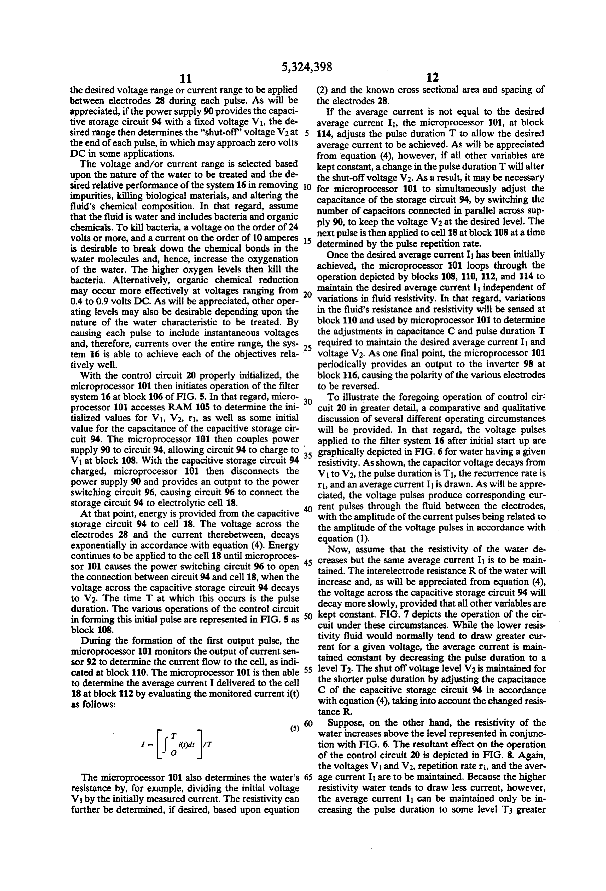
Page 14
than T1. Also, to ensure that the voltage V2 is reached be limited to the embodiments illustrated and discussed at time T3, the capacitive storage circuit 94 must be herein.
adjusted in accordance with equation (4), taking into The embodiments of the invention in which an exclu account the simultaneous alteration of the interelec sive property or privilege is claimed are defined as trode resistance R. follows:
Now suppose that the water resistivity remains essen 1. A method of controlling the operation of an elec tially the same as that represented in conjunction with trolytic system for use in the treatment of a fluid exhibit FIG. 6 but the average current is to be increased to ing a potentially variable characteristic, said method some level I2 greater than I. Such a variation might be comprising the steps of:
desired to, for example, place greater emphasis upon the O producing a plurality of pulses of electrical energy breaking down of chemical bond by the water mole for application to the electrolytic system, the plu cules to increase oxygenation. As shown in FIG. 9, the rality of pulses exhibiting parameters including a voltage V1 remains constant. Also assume that voltage pulse repetition rate, pulse duration, and pulse am V2 is to remain constant because the range represented plitude;
between voltage V1 and V2 provides optimal treatment 15 evaluating the potentially variable characteristic of of the water. The pulse duration is kept at T1 and the the fluid;
average current is increased to 12 by decreasing the automatically controlling one of the parameters ex current repetition rate to some level r2. In the event the hibited by the plurality of pulses in response to the water resistivity varies, this average current I2 could evaluation of the potentially variable characteristic then be maintained by altering the pulse duration in the 20 of the fluid.
manner previously discussed in connection with FIGS. 2. The method of claim 1, wherein said step of evalu 7 and 8. ating comprises the step of producing an output repre Suppose instead that it is desired to apply a greater sentative of the fluid's resistivity. range of voltages to the electrolytic cell 18 than is de 3. The method of claim 2, wherein said step of auto picted in conjunction with FIG. 6, while still achieving 25 an average current I. One potential operation of the matically controlling is performed to allow the electro control circuit 20 is graphically depicted in FIG. 10. In of variationstoin treat lytic system the the fluid substantially independent fluid's resistivity.
that regard, the maximum capacitive voltage remains
V1. However, the voltage across the capacitive storage trolling comprises the step 1,ofwherein
adjusting the pulse dura circuit 94 is allowed to decay to some voltage V3 that is 30 tion.
less than V2. The same pulse duration T can be main 5. The method of claim 1, wherein said step of pro tained by adjusting the capacitance of the capacitive ducing said plurality of pulses comprises the steps of: storage circuit 94. To maintain the desired average storing electrical energy on a capacitor; and current 1, however, the recurrence rate must be in repetitively connecting the capacitor to, and discon creased to some level r3. As will be appreciated, the 35 necting the capacitor from, the electrolytic system.
voltage range could be alternatively narrowed by de creasing the recurrence rate. 6. The method of claim 5, wherein said step of storing As will be appreciated from the foregoing discussion electrical energy comprises the step of establishing a of the various modes of operation of control circuit 20, voltage across said capacitor at some predetermined numerous variations can be implemented. Thus, for 40 initial level and wherein said step of repetitively con example, the magnitude of the initial voltage V could necting the capacitor to, and disconnecting the capaci be periodically altered to further control the range of tor from, the electrolytic system includes the step of voltages or the average current applied to the cell. In automatically disconnecting the capacitor from the that regard, the DC power supply 90 could be con electrolytic system when the voltage across said capaci structed so that the initial voltage V across the capaci 45 tor has decayed to some predetermined subsequent tive storage circuit 94 is relatively high for one pulse to level.
treat a first characteristic and then lower for a predeter tively 7. The method of claim 6, wherein said step of repeti mined number of subsequent pulses to treat a second connecting the capacitor to, and disconnecting characteristic. This pattern would then be repeated. the capacitor from, the electrolytic system is repeated at The capacitive storage circuit 94 could even be elimi 50 the pulse repetition rate.
nated by sweeping the output of supply 90 over the 8. The method of claim 6, wherein the electrolytic desired range of voltages. system is for use in the treatment of more than one Also, a variable capacitance need not be available aspect of the fluid and wherein said initial level and from the capacitive storage circuit 94. In that event, subsequent level are selected to enhance the system's however, the discharge rate will vary with changes in 55 ability to treat the more than one aspect of the fluid. the resistivity of the fluid and it may not be possible to 9. The method of claim 8, wherein said initial level is maintain a desired shut off voltage V2 independent of roughly sixty volts and said subsequent level is roughly changes in pulse duration. zero volts.
Those skilled in the art will recognize that the em 10. The method of claim 1 including evaluating the bodiments of the invention disclosed herein are exem potentially variable characteristic of the fluid by sensing plary in nature and that various changes can be made a condition indicative of the potentially variable charac therein without departing from the scope and the spirit teristic and supplying an output representing the poten of the invention. In this regard, the invention can be tially variable characteristic, and automatically control employed in the treatment of fluids other than water ling one of the parameters exhibited by the plurality of used, for example, in lubrication, hydraulic, and pneu pulses in response to the evaluation of the potentially matic systems. Because of the above and numerous variable characteristic of the fluid by supplying the other variations and modifications that will occur to output to a microprocessor and using the microproces those skilled in the art, the following claims should not sor to control such one of the parameters.
Page 15
11. The method of claim 10, including using the mi sure that the pulse repetition rate and end amplitude are croprocessor to control the pulse duration. established at some predetermined levels. 12. A method of electrolytically treating water in a 20. The circuit of claim 19, wherein said electrolytic manner that is relatively independent of variations in fluid treatment system is for use in the treatment of the electrical resistivity of the water, said method com more than one aspect of the fluid and wherein said start prising the steps of: amplitude and said end amplitude are selected to en positioning the water between at least one pair of hance the system's ability to treat the more than one electrodes; aspect of the fluid.
producing a voltage across a capacitor; 21. The circuit of claim 20, wherein said start ampli selectively coupling the capacitor to the electrodes, O tude is roughly thirty amperes and said end amplitude is causing the voltage across the capacitor to decay roughly 22.
zero amperes.
The circuit of claim 19, wherein said control and a current to flow through the water between means is further for controlling the pulse duration ex the at least one pair of electrodes; hibited by said current pulses in response to said sensing sensing a condition indicative of the resistivity of the means to ensure that the average current provided to water; and 15 the electrodes remains substantially independent of selectively disconnecting the capacitor from the elec variations in the resistivity of the fluid passed between trodes when the voltage across the capacitor de cays to a predetermined threshold, said steps of the23.electrodes.
selectively coupling and selectively disconnecting meansThe circuit of claim 15, wherein said delivery being repeated automatically at a predetermined 20 switching means fora capacitor comprises for storing energy and selectively connecting said capaci repetition rate and being separated by an interval tor to and disconnecting said capacitor from the elec whose length is dependent upon the sensed condi trodes, tion indicative of resistivity of the water. 24. Apparatus for electrolytic treatment of a fluid that 13. The method of claim 12, including providing an may exhibit a varying resistivity, said apparatus com output representing the resistivity of the water, supply 25 prising:
ing the output to a microprocessor, and using the micro at least one pair of electrodes, said electrodes defining processor to trigger the step of selectively disconnect a fluid flow path therebetween; ing and selectively coupling the capacitor to the elec a capacitor for storing electrical energy for delivery trodes. to said pair of electrodes; 14. The method of claim 13, including using the mi 30 a switching circuit for causing energy stored by the croprocessor to trigger the steps of selectively discon capacitor to be delivered to said pair of electrodes necting and selectively coupling the capacitor to the as a plurality of current pulses; electrodes so as to adjust the pulse duration. an ammeter for producing an output representative of 15. A circuit for providing a desired electric current the current pulses delivered to said pair of elec between the electrodes of an electrolytic fluid treatment 35 trodes;
system, substantially independent of variations in a vari a control circuit for automatically controlling said able characteristic of the fluid passed between the elec switching circuit in response to the output of said trodes and treated by the system, said circuit compris annetter.
ling: 25. The apparatus of claim 24, wherein said current sensing means for sensing variations in the variable pulses exhibit a plurality of characteristics and wherein characteristic of the fluid passed between the elec said control circuit and switching circuit are for cooper trodes; atively controlling at least one of said plurality of char delivery means for delivering a plurality of electric acteristics.
current pulses to the electrodes, said electric cur 26. The apparatus of claim 25, wherein said charac rent pulses exhibiting a pulse duration, pulse repeti teristics exhibited by said current pulses include dura tion rate, and pulse amplitude; and 45 tion, amplitude, and repetition rate and wherein said control means, responsive to said sensing means, for control circuit and switching circuit are for coopera automatically controlling said delivery means to tively establishing amplitude and repetition rate at some ensure that the desired electric current provided to predetermined levels and for cooperatively establishing the electrodes remains substantially independent of duration in response to the output of said ammeter. variations in the variable characteristic of the fluid 50 27. A method of electrolytically treating several as passed between the electrodes. pects of water which method comprises the steps of: 16. The circuit of claim 15, in which the sensing passing the water between at least one pair of elec means includes means for providing an output repre trodes;
senting the variable characteristic, the control means applying a varying voltage of between sixty volts and zero volts across the electrodes to effect the de including a microprocessor receiving said output and 55 sired treatment of the water by producing a voltage controlling the delivery means. across a capacitor, selectively coupling the capaci 17. The circuit of claim 15, wherein said sensing tor to the electrodes, causing the voltage across the means is for sensing a completion indicative of varia capacitor to decay and selectively disconnecting tions in the resistivity of the fluid. the capacitor from the electrodes when the voltage 18. The circuit of claim 17, wherein said sensing across the capacitor decays to a predetermined means is for sensing a condition indicative of variations threshold; and in the amplitude of the current pulses delivered to the sensing the conductivity of the water, said steps of electrodes. selectively coupling and selectively disconnecting 19. The circuit of claim 15, wherein each current being repeated automatically at a predetermined pulse has a start point and an end point and the pulse 65 repetition rate and being separated by an interval of amplitude decays from a start amplitude at the start time whose length is dependent upon the sensed point to an end amplitude at the end point, said control conductivity of: the water. means being for controlling said delivery means to en
Page 16
UNITED STATES PATENT ANDTRADEMARK OFFICE
CERTIFICATE OF CORRECTION
INVENTOR(S) : R.K. Erickson et al.
It is certified that error appears in the above-indentified patent and that said Letters Patent is hereby Corrected as shown below:
(56) Ref. Cited Insert-4,842,724 06/1989 Bray et al......210/104- -
56 Ref. Cited "204/152" should read -104/152
(56) Ref. Cited Insert -5,034,123 07/1991 Tanaka et al......210/195.1-
56 Ref. Cited "European Pat. Off..." should read-European Pat. Off.
56) Ref Cited "Fed. Rep. of Germany." should read-Fed. Rep. of Germany
Claim 17 2 "completion" should read-condition
Signed and Sealed this
Twenty-second Day of November, 1994
BRUCE LEEMAN
Attesting Officer Commissioner of Patents and Trademarks
Provenance
- Collection
- Cited prior art
- Original PDF
- patentimages.storage.googleapis.com →
- Filed
- 1992-06-19
- Pages
- 16
- Method
- pdftotext (the PDF's own text layer) + pdftoppm 300dpi page scans
- Source
- Google Patents bibliographic record
- Granted
- 1994-06-28
- Inventors
- Robert K. Erickson; Francois X. Prinz; Water Regeneration Systems Inc
- Transcribed from
- patentimages.storage.googleapis.com →