patent · US5281026
Printed circuit board with cooling monitoring system
25 January 1994
Page 1 — bibliographic record
United States Patent (19) (11 Patent Number: 5,281,026 Bartilson et al. (45) Date of Patent: Jan. 25, 1994 54 PRINTED CIRCUIT BOARD WITH 4,854,731 8/1989 Jenkins . COOLING MONITORING SYSTEM 5924,263 6/1991 Laine et al............................ 165/40
(75) Inventors: Bradley W. Bartilson; Elliot F. 5,230,564 7/1993 Bartilson et al. .................... 374/78 Schlimme, both of Chippewa Falls, summe, to pp. FOREIGN PATENT DOCUMENTS (73) Assignee: Sty Research, Inc., Chippewa Falls, 012.9966 2/1984
European Pat. Off..
S. 1274-16S 11/1986 U.S.S.R. .
21 Appl. No.: 56,650 OTHER PUBLICATIONS (22) Filed: May 3, 1993 "High-Performance Heat Sinking for VLSI," Tucker O- 8 man et al., IEEE Electron Device Letters, vol. EDL-2,
Related U.S. Application Data No. 5, pp. 126-129, May 1981.
62) Division of Ser. No. 853,983, Mar. 20, 1992, Pat. No. "Heat Transfer From Pin-Fins Situated in an Oncom 5,230,564. ing Longitudinal Flow Which Turns to Crossflow,” 51) Int. Cl. ............................................. G01K 13/00 o 52 U.S. Cl. .................................... 374/143; 374/183; (List continued on next page.) 361/384; 361/694; 73/756 Primary Examiner-William A. Cuchlinski, Jr.
(58) Field of Search ............... 374/42, 143, 163, 178,
Assistant Examiner-G. -.
Bradley Bennett
Edell, Welter Firm-Merchant, Gould, Smith,
Schmidt
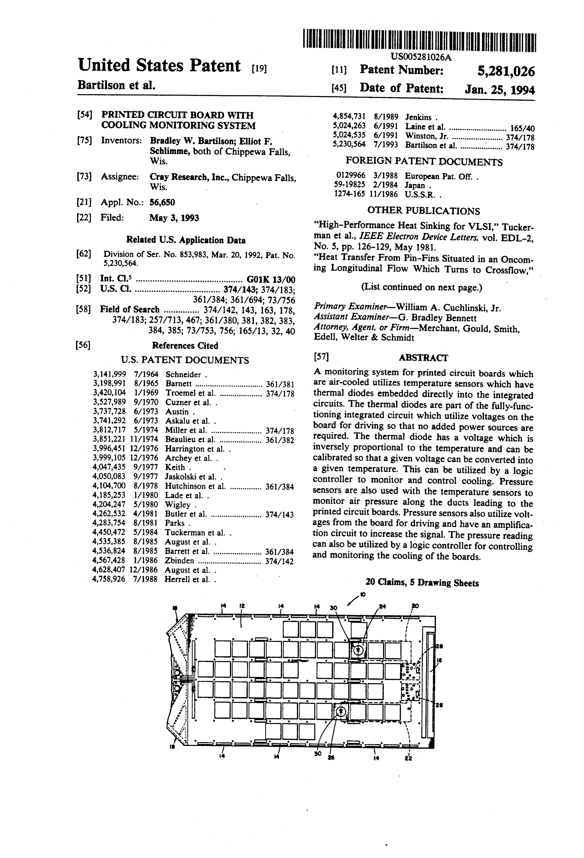
A monitoring system for printed circuit boards which ; : A. 361/38 are air-cooled utilizes temperature sensors which have
thermal The diodesthermal embedded directly into the integrated diodes are part of the fully-func 3,737,728 6/1973 Austin . tioning integrated circuit which utilize voltages on the 3,741,292 6/1973 Askalu et al. . board for driving so that no added power sources are E. A. Mills et s& wasa sw a Poa as a CA. required. The thermal diode has a voltage which is 451 12/1976 .." inversely proportional to the temperature and can be 3.69605 i2/1976 Archeyet al. calibrated so that a given voltage can be converted into 4,047,435 9/1977 Keith . a given temperature. This can be utilized by a logic 4,050,083 9/1977 Jaskolski et al. . controller to monitor and control cooling. Pressure 4,104,700 8/1978 Hutchinson et al. ............... 36/384 sensors are also used with the temperature sensors to 2. 1/ W et al. . monitor air pressure along the ducts leading to the
circuit boards. Pressure sensors also utilize volt ages from the board for driving and have an amplifica 4,450,472 5/1984 Tuckerman et al. . tion circuit to increase the signal. The pressure reading 4,535,385 8/1985 August et al. . can also be utilized by a logic controller for controlling 4,536,824 8/1985 Barrett et al. ....................... 361/384 and monitoring the cooling of the boards. 4,567,428 1/1986 Zbinden .............................. 374/142
4,758,926 7/1988 Herrell et al. . 20 Claims, 5 Drawing Sheets
Page 2
OTHER PUBLICATIONS
Sparrow et al., Int. J. Heat Mass Transfer, vol. 25, No. 5, "Impingement Cooling of Electronics," Hollworth et pp. 603-614, 1982. al., Alfred University, HTD-vol. 111, pp. 89-96, 1989. "Performance Comparisons Among Geometrically Dife (no month).
ferent Pin-Fin Arrays Situated in an Oncoming Longi "Air Jet Impingement Cooling of an Array of Simu tudinal Flow," Larson et al., Int. J. Heat Mass Transfer, lated Electronics Packages," T. Hamadah, HTD-vol. vol. 25, No. 5, pp. 723-725, 1982. 111, pp. 97-105, 1989. (no month). "Heat Transfer With Impinging Jets,” R. Goldstein, "Impingement Cooling of a Simulated Electronics Proceedings of the Symposium on Nonlinear Problems in Package with a Square Array of Round Air Jets,” T. Energy Engineering, Argon National Labs, pp. 7-15, Hamadah, HTD-vol. 111, pp. 107-112, 1989. (no 983. month).
"Local Heat Transfer to Staggered Arrays of Imping "Local Heat Transfer Coefficients Under an Axisym ing Circular Air Jets," Behbahani et al., Transactions of metric, Single-Phase Liquid Jet," Stevens et al., HTD the ASME, vol. 105, pp. 354-359, 1983. (no month). vol. 111, pp. 113-119, 1989. (no month). "Heat-Transfer Microstructures for Integrated Cir "Jet Impingement Flow Boiling of a Mixture of FC-72 cuits," D. Tuckerman, Stanford University, pp. 1-141, and FC-87 Liquids on a Simulated Electronic Chip,” Feb. 1984. Nonn et al., HTD-vol. 111, pp. 121-128, 1989. (no month).
"Heat Transfer in Forced Convection Through Fins," "Thermal Performance Characteristics of Air-Cooled R. Keyes, IEEE Transactions on Electron Devices, vol. Cold Plates for Electronic Cooling,' Yimer et al., ED-31, No. 9, pp. 1218-1221, Sep. 1984. HTD-vol. 111, pp. 143-148, 1989. (no month). "IBM Packs in High Density Circuits' Computer De "Flow Visualization in an Impinging Circular Air Jet,” sign, No. 14, pp. 254-255, Dec. 1984. Behbahani et al., HTD-vol. 112, pp. 143-148, 1989. (no "Effect of Inlet, Exit, and Fin Geometry on Pin Fins month).
Situated in a Turning Flow,” Sparrow et al., pp. "Prediction of Surface Temperature and Heat Flux of a 1039-1053, 1984. (no month). Microelectronic Chip With Jet Impingement Cooling,' "Experimental Investigation of Multi-Jet Impingement Wang et al., Journal of Electronic Packaging, vol. 112, Cooling of an Array of Microelectronic Heat Sources,' pp. 57-62, Mar. 1990.
Jiji et al., The City College of the City University of "On the Accommodation of Coolant Flow Paths in New York, pp. 1-31, Aug. 1986. High-Density Packaging,' W. Nakayama, InterSociety "Thermal Impact of Double-Sided Printed Circuit Conference on Thermal Phenomena, pp. 101-112, 1990. Cards,' T. Davis, IBM Systems Technology Division, (no month).
pp. 11-15, 1987. (no month). "Impingement Cooling of Electronics: Effects of Vent "Forced-Convection, Liquid-Cooled, Microchannel ing Through Circuit Board,' Hollworth et al., Alfred Heat Sinks for High-Power-Density Microelectron University, pp. 80-96, date unknown.
Page 3
Drawing sheet — no readable text.
Page 4
Drawing sheet — no readable text.
Page 5
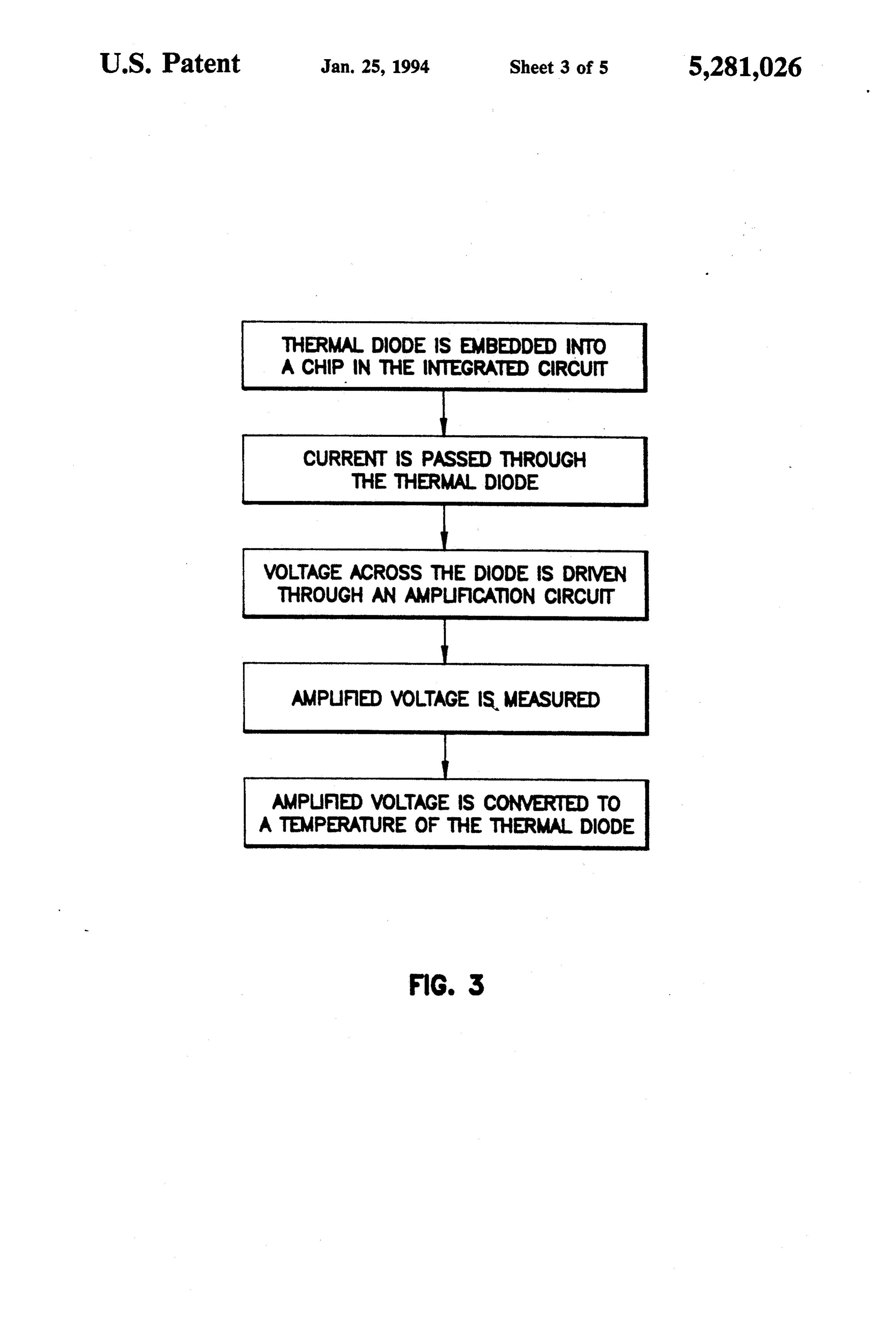
THERMAL DIODE IS EMBEDDED INTO
A CHIP IN THE INTEGRATED CIRCUIT
CURRENT IS PASSED THROUGH
THE THERMAL DODE
VOLTAGE ACROSS THE DODE IS ORMEN
THROUGH AN AMPUFCAON CIRCUIT
AMPuFED VOLTAGE IS, MEASURED
AMPUFED VOLTAGE IS CONMERED TO
A TEMPERATURE OF THE THERMA DIODE
FIG 3
Page 6
Drawing sheet — no readable text.
Page 7
Drawing sheet — no readable text.
Page 8
being used, the diode signal can be driven off the board
PRINTED CIRCUIT BOARD WITH COOLING without special adapting components being added. MONITORING SYSTEM In conjunction with the thermal diode, an amplifica tion circuit is used to boost the voltage for driving and
BACKGROUND OF THE INVENTION 1. Field of 5 for improved signal integrity. The amplification circuit the Invention is also driven directly from voltages of the circuit so
This application is a division of U.S. patent applica that no additional power sources or specialized adapta tion Ser. No. 07/853,983, filed Mar. 20, 1992, which tion is required for the amplification circuit. issued as U.S. Pat. No. 5,230,564 on Jul. 27, 1993. With the present invention, the temperature is di The present invention relates to an apparatus and 10 rectly measured in the circuit, rather than a method of measuring the temperature indirectly by sensing the air method for directly measuring cooling air pressure and the temperature of an integrated circuit. 2. Description temperature around the circuit or placing a sensor on of the Prior Art the circuit board and extrapolating the temperature. Measurement of integrated circuit board tempera In a similar manner, pressure can be determined uti tures is critical for continuous operation without over 15 lizing an arrangement having pressure sensors with associated circuits and amplification circuits. A pressure heating and damaging the circuits. Integrated circuits sensor detects the air flow prior to cooling the circuit may develop a build up of heat at various points in the board and then has the signal amplified. Again, circuit circuit. If the temperature is too high at any point, the circuit may be damaged. Therefore circuits often use air 20 board voltages are utilized so that no special adaptation or additional power sources are necessary. The pressure or fluid cooling systems to prevent overheating. To ensure that the cooling system is working properly and isdriving measured by the sensor and the signal is amplified for that the circuit will not be damaged, the temperature of rity. Thethesignal signal off-board and to improve signal integ can then be converted into a pressure to the circuit is monitored.
Heretofore, with air cooling, circuit temperatures 25 detect that proper air flow is occurring. With both the have been measured indirectly utilizing sensors measur air pressure and circuit temperature being measured, it ing the air temperature around potential "hot spots" in can be determined that the cooling apparatus is func the circuit rather than directly measuring the circuit tioning correctly. This combination of pressure mea temperature. The temperature of the integrated circuit surement at the air stream and direct temperature mea must then be extrapolated from the sensed air tempera 30 surement provides for improved monitoring. ture. However, this technique is not entirely satisfac novelty whichvarious
These and other advantages and features of characterize the invention are pointed tory as a number of variables can affect the air tempera ture so that the reading may not reflect the true temper out with particularity in the claims annexed hereto and forming a part hereof. However, for a better under ature of the integrated circuit. The problem of accuracy standing of the invention, its advantages, and the ob is especially difficult when the integrated circuit uses air 35 jects obtained by its use, reference should be made to cooling. Differences in flow and temperature variations the drawings which form a further part hereof, and to in other components may have a significant influence on the accompanying descriptive matter, in which there is the air temperature while the temperature of the inte illustrated and described a preferred embodiment of the grated circuit may vary only slightly. invention.
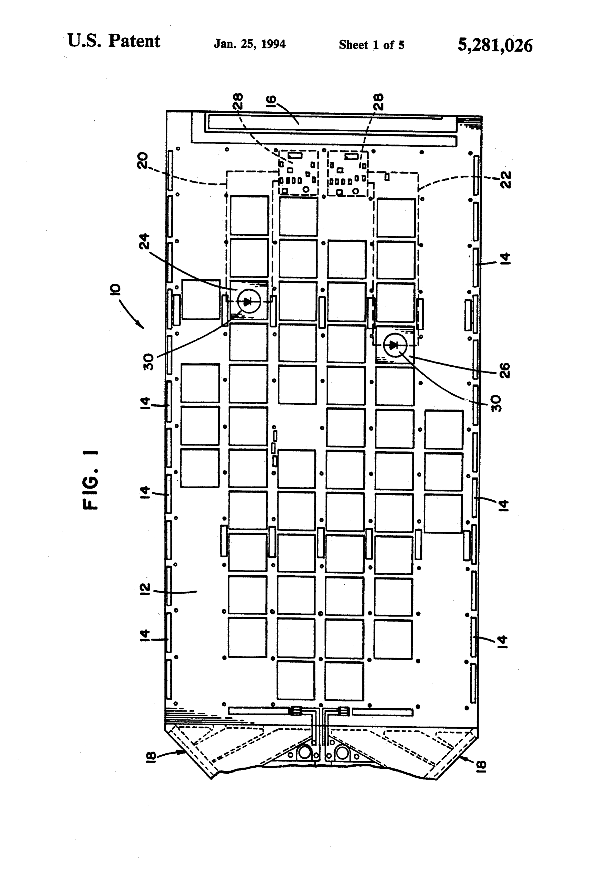
Sensors have also been imbedded in the circuit board next to the circuit. As with sensing air temperature, this BRIEF DESCRIPTION OF THE DRAWINGS method is indirect and requires extrapolation to give an In the drawings, wherein like reference letters and estimated circuit temperature. Devices for measuring numerals temperature and pressure have heretofore required an the severalindicate views:
corresponding elements throughout added separate circuit to drive the temperature sensor 45 FIG. 1 shows a top plan view of an integrated circuit so that extra circuitry is needed along with an additional board having a temperature-sensing apparatus and pres power source.
It can be seen then that a temperature monitoring sure-sensing apparatus according to the principles of the present invention;
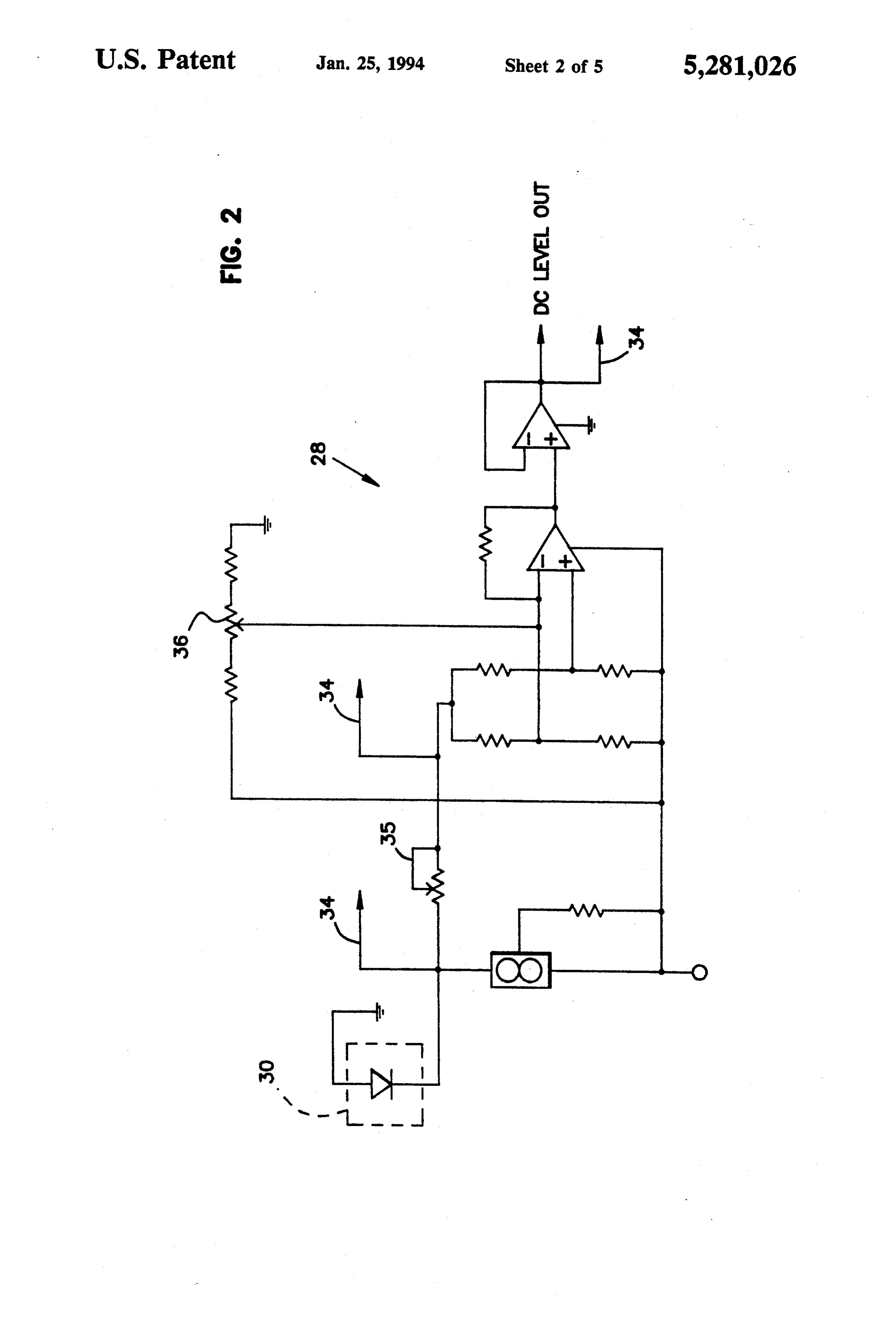
system is needed which directly measures temperature of an integrated circuit and which is driven from exist SO forFIG. 2 shows a schematic of an amplification circuit the temperature-sensing apparatus shown in FIG. 1;
ing voltage in the integrated circuit. FIG. 3 shows a block diagram of a method of direct SUMMARY OF THE INVENTION temperature measurement;
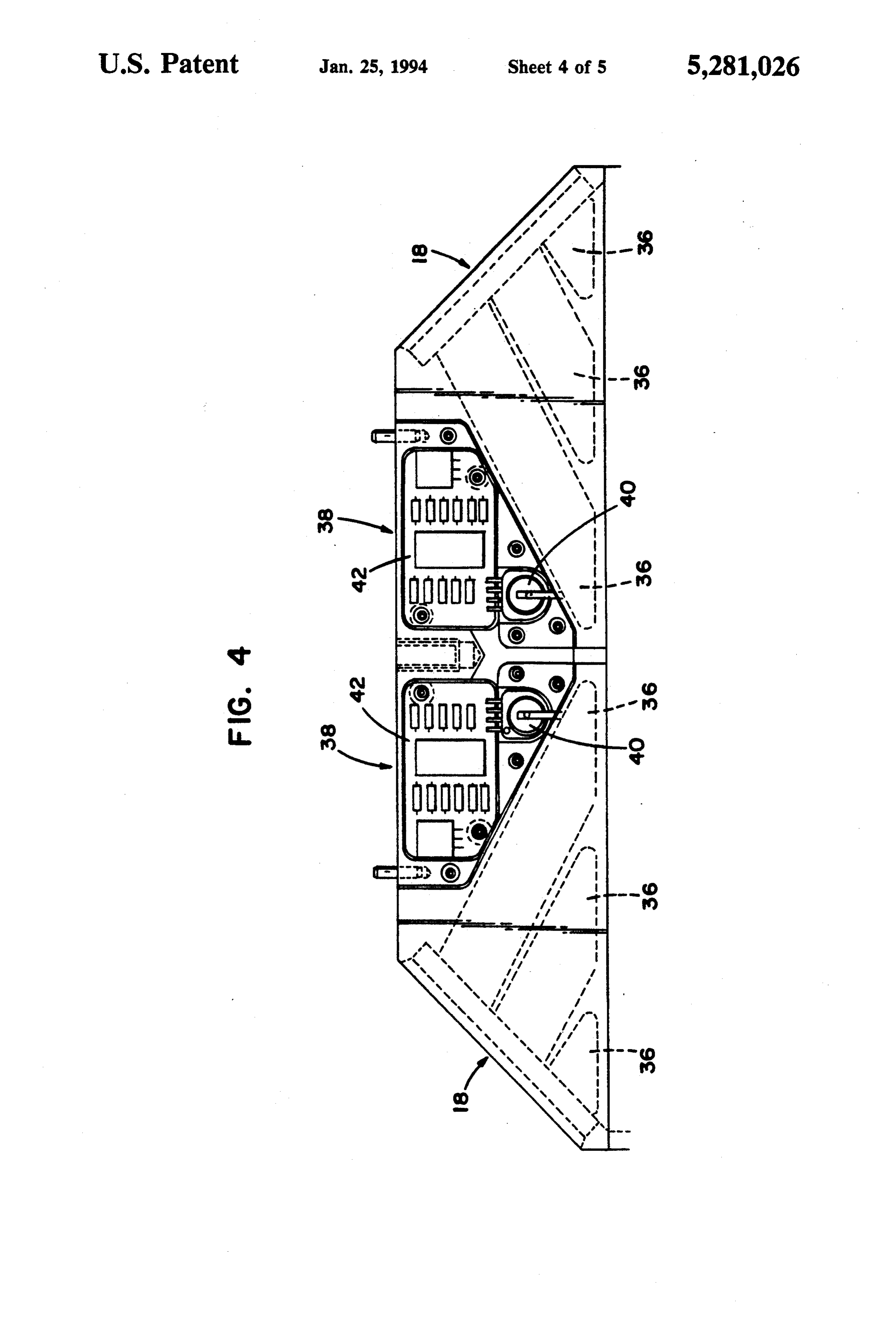
FIG. 4 shows a top plan view of a pressure sensor and
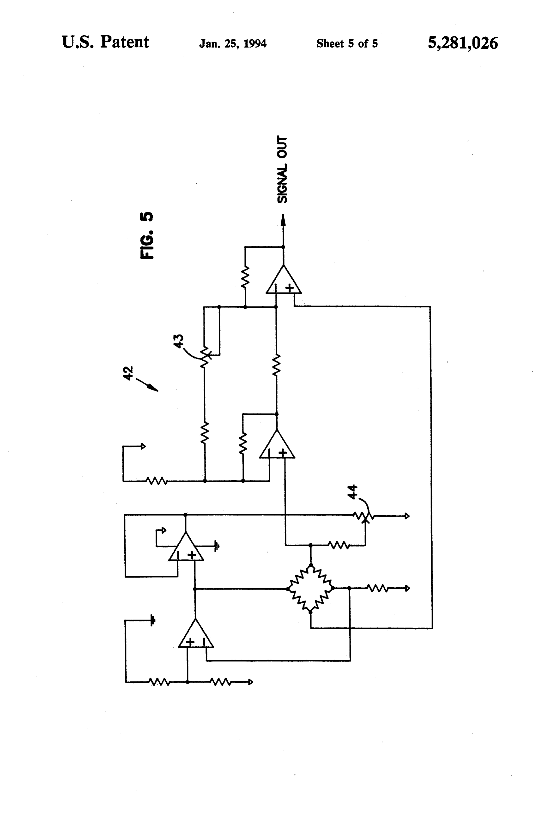
The present invention is directed to a method and associated amplification circuit; and, apparatus for direct measurement of temperature and 55 FIG. 5 shows a schematic of a circuit for the pres pressure for integrated circuit boards. According to the sure-sensing apparatus.
present invention, a thermal diode is embedded directly DETAILED DESCRIPTION OF THE into a functioning integrated circuit. The thermal diode has a voltage which varies inversely with its tempera PREFERRED EMBODIMENT(S) ture, so that as the temperature of the diode increases, Referring now to the drawings, and in particular the voltage across the diode decreases. It can be appre referring to FIG. 1, there is shown a printed circuit ciated that since the diode is part of the integrated cir board 10 which may be part of a circuit board module cuit, with the diode calibrated, the voltage can be con such as typically is placed in stacks of circuit boards verted back to a corresponding temperature, so that the which are used, as for example, with super computers. temperature measurement is direct, rather than indirect 65 The printed circuit board 10 has a plurality of inte by sensing the air around the circuit. grated circuits placed across a face 12 of the board and The thermal diode is driven by the existing voltages a plurality of edge connectors 14 along sides of the of the integrated circuit board. Since board voltages are board for making electrical connections to other boards
Page 9
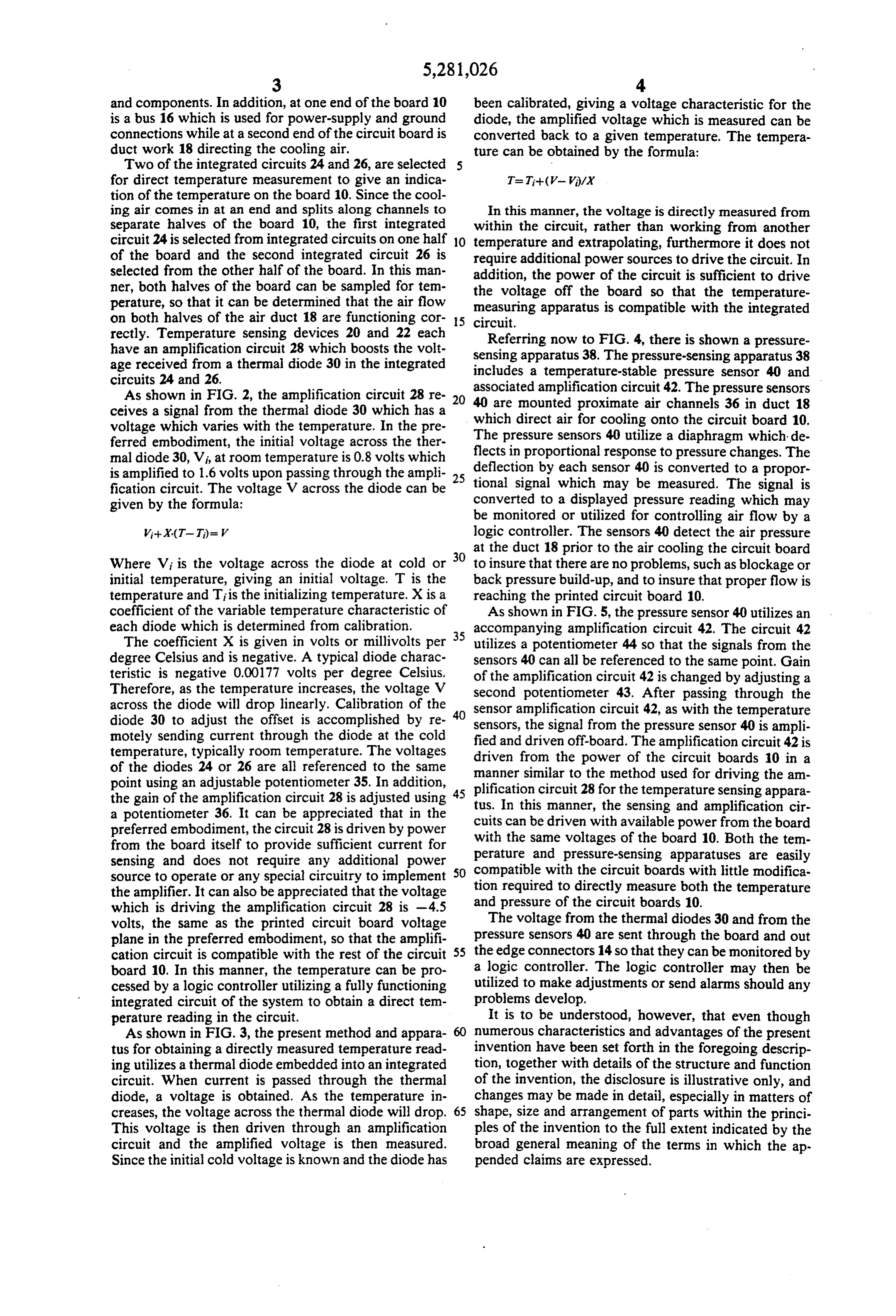
and components. In addition, at one end of the board 10 been calibrated, giving a voltage characteristic for the is a bus 16 which is used for power-supply and ground diode, the amplified voltage which is measured can be connections while at a second end of the circuit board is converted back to a given temperature. The tempera duct work 18 directing the cooling air. ture can be obtained by the formula: Two of the integrated circuits 24 and 26, are selected for direct temperature measurement to give an indica tion of the temperature on the board 10. Since the cool ing air comes in at an end and splits along channels to In this manner, the voltage is directly measured from separate halves of the board 10, the first integrated within the circuit, rather than working from another circuit 24 is selected from integrated circuits on one half O temperature and extrapolating, furthermore it does not of the board and the second integrated circuit 26 is require additional power sources to drive the circuit. In selected from the other half of the board. In this man addition, the power of the circuit is sufficient to drive ner, both halves of the board can be sampled for tem the voltage off the board so that the temperature perature, so that it can be determined that the air flow measuring apparatus is compatible with the integrated on both halves of the air duct 18 are functioning cor 5 circuit.
rectly. Temperature sensing devices 20 and 22 each Referring now to FIG. 4, there is shown a pressure have an amplification circuit 28 which boosts the volt sensing apparatus 38. The pressure-sensing apparatus 38 age received from a thermal diode 30 in the integrated includes a temperature-stable pressure sensor 40 and circuits 24 and 26.
As shown in FIG. 2, the amplification circuit 28 re 20 associated amplification circuit 42. The pressure sensors ceives a signal from the thermal diode 30 which has a 40 are mounted proximate air channels 36 in duct 18 voltage which varies with the temperature. In the pre whichpressure direct air for cooling onto the circuit board 10. ferred embodiment, the initial voltage across the ther The flects in sensors 40 utilize a diaphragm which de proportional response to pressure changes. The mal diode 30, Vi, at room temperature is 0.8 volts which is amplified to 1.6 volts upon passing through the ampli 25 deflection by each sensor 40 is converted to a propor fication circuit. The voltage V across the diode can be tional signal which may be measured. The signal is given by the formula: converted to a displayed pressure reading which may be monitored or utilized for controlling air flow by a logic controller. The sensors 40 detect the air pressure at the duct 18 prior to the air cooling the circuit board
Where Vi is the voltage across the diode at cold or 30 to insure that there are no problems, such as blockage or initial temperature, giving an initial voltage. T is the back pressure build-up, and to insure that proper flow is temperature and Tiis the initializing temperature. X is a reaching the printed circuit board 10. coefficient of the variable temperature characteristic of As shown in FIG. 5, the pressure sensor 40 utilizes an each diode which is determined from calibration.
35 accompanying amplification circuit 42. The circuit 42
The coefficient X is given in volts or millivolts per utilizes a potentiometer 44 so that the signals from the degree Celsius and is negative. A typical diode charac sensors 40 can all be referenced to the same point. Gain teristic is negative 0.00177 volts per degree Celsius. of the amplification circuit 42 is changed by adjusting a Therefore, as the temperature increases, the voltage V second potentiometer 43. After passing through the across the diode will drop linearly. Calibration of the 40 sensor amplification circuit 42, as with the temperature diode 30 to adjust the offset is accomplished by re sensors, the signal from the pressure sensor 40 is ampli motely sending current through the diode at the cold temperature, typically room temperature. The voltages fied and driven off-board. The amplification circuit 42 is driven from the power of the circuit boards 10 in a of the diodes 24 or 26 are all referenced to the same manner point using an adjustable potentiometer 35. In addition, 45 plificationsimilar to the method used for driving the am the gain of the amplification circuit 28 is adjusted using tus. In thiscircuit 28 for the temperature sensing appara manner, the sensing and amplification cir a potentiometer 36. It can be appreciated that in the cuits can be driven with available power from the board preferred embodiment, the circuit 28 is driven by power with the same voltages of the board 10. Both the tem from the board itself to provide sufficient current for sensing and does not require any additional power perature and pressure-sensing apparatuses are easily source to operate or any special circuitry to implement 50 compatible with the circuit boards with little modifica the amplifier. It can also be appreciated that the voltage tion and required to directly measure both the temperature pressure of the circuit boards 10.
which is driving the amplification circuit 28 is -4.5 volts, the same as the printed circuit board voltage The voltage from the thermal diodes 30 and from the plane in the preferred embodiment, so that the amplifi pressure sensors 40 are sent through the board and out cation circuit is compatible with the rest of the circuit 55 the edge connectors 14 so that they can be monitored by board 10. In this manner, the temperature can be pro a logic controller. The logic controller may then be cessed by a logic controller utilizing a fully functioning utilized to make adjustments or send alarms should any integrated circuit of the system to obtain a direct tem problems develop.
perature reading in the circuit. It is to be understood, however, that even though As shown in FIG. 3, the present method and appara numerous characteristics and advantages of the present tus for obtaining a directly measured temperature read invention have been set forth in the foregoing descrip ing utilizes a thermal diode embedded into an integrated tion, together with details of the structure and function circuit. When current is passed through the thermal of the invention, the disclosure is illustrative only, and diode, a voltage is obtained. As the temperature in changes may be made in detail, especially in matters of creases, the voltage across the thermal diode will drop. 65 shape, size and arrangement of parts within the princi This voltage is then driven through an amplification ples of the invention to the full extent indicated by the circuit and the amplified voltage is then measured. broad general meaning of the terms in which the ap Since the initial cold voltage is known and the diode has pended claims are expressed.
Page 10
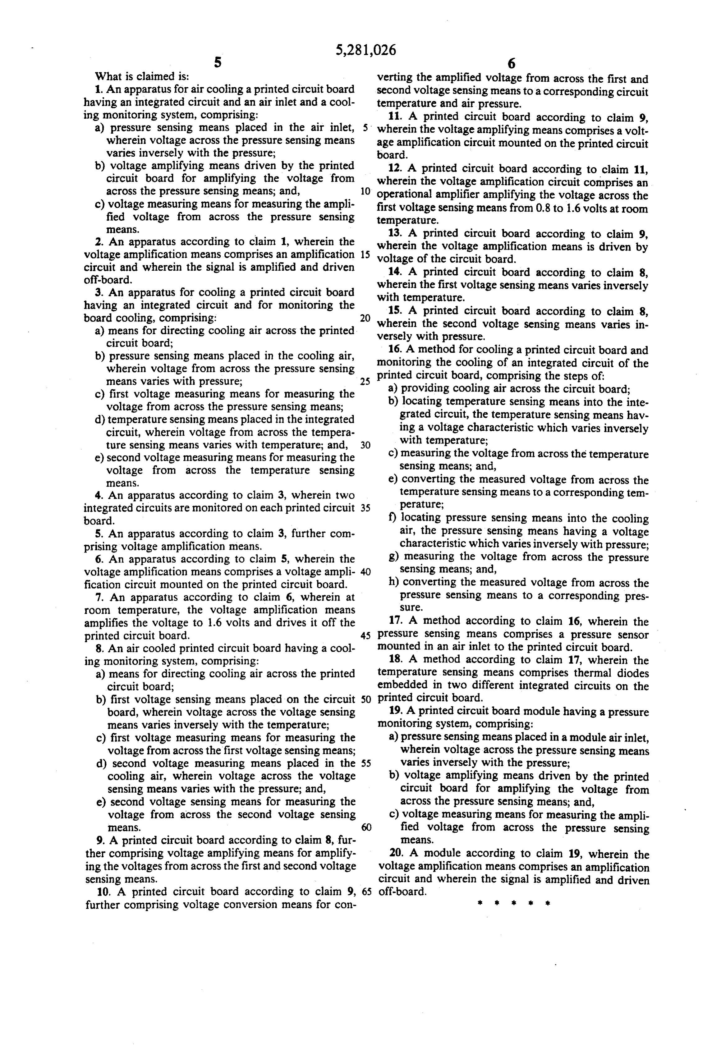
What is claimed is: verting the amplified voltage from across the first and 1. An apparatus for air cooling a printed circuit board second voltage sensing means to a corresponding circuit having an integrated circuit and an air inlet and a cool temperature and air pressure.
ing monitoring system, comprising: 11. A printed circuit board according to claim 9, a) pressure sensing means placed in the air inlet, wherein the voltage amplifying means comprises a volt wherein voltage across the pressure sensing means age amplification circuit mounted on the printed circuit varies inversely with the pressure; board.
b) voltage amplifying means driven by the printed 12. A printed circuit board according to claim 11, circuit board for amplifying the voltage from wherein the voltage amplification circuit comprises an across the pressure sensing means; and, 10 operational amplifier amplifying the voltage across the c) voltage measuring means for measuring the ampli first voltage sensing means from 0.8 to 1.6 volts at room fied voltage from across the pressure sensing temperature.
eaS 2. An apparatus according to claim 1, wherein the 13. A printed circuit board according to claim 9, wherein the voltage amplification means is driven by voltage amplification means comprises an amplification 15 voltage circuit and wherein the signal is amplified and driven of the circuit board. off-board. 14. A printed circuit board according to claim 8, 3. An apparatus for cooling a printed circuit board wherein the first voltage sensing means varies inversely having an integrated circuit and for monitoring the with temperature.
15. A printed circuit board according to claim 8,
wherein the second voltage sensing means varies in a) means for directing cooling air across the printed versely with pressure.
circuit board; 16. A method for cooling a printed circuit board and b) pressure sensing means placed in the cooling air, monitoring the cooling of an integrated circuit of the wherein voltage from across the pressure sensing printed circuit board, comprising the steps of:
a) providing cooling air across the circuit board;
c) first voltage measuring means for measuring the b) locating temperature sensing means into the inte voltage from across the pressure sensing means; grated circuit, the temperature sensing means hav d) temperature sensing means placed in the integrated circuit, wherein voltage from across the tempera ing a voltage characteristic which varies inversely ture sensing means varies with temperature; and, 30 with temperature;
e) second voltage measuring means for measuring the c) measuring the voltage from across the temperature voltage from across the temperature sensing sensing means; and, aS e) converting the measured voltage from across the 4. An apparatus according to claim 3, wherein two temperature sensing means to a corresponding tem integrated circuits are monitored on each printed circuit 35 perature;
board. f) locating pressure sensing means into the cooling 5. An apparatus according to claim 3, further com air, the pressure sensing means having a voltage prising voltage amplification means. characteristic which varies inversely with pressure; 6. An apparatus according to claim 5, wherein the g) measuring the voltage from across the pressure voltage amplification means comprises a voltage ampli sensing means; and, fication circuit mounted on the printed circuit board. h) converting the measured voltage from across the 7. An apparatus according to claim 6, wherein at pressure sensing means to a corresponding pres room temperature, the voltage amplification means Sle, amplifies the voltage to 1.6 volts and drives it off the 17. A method according to claim 16, wherein the printed circuit board. 45 pressure sensing means comprises a pressure sensor 8. An air cooled printed circuit board having a cool mounted in an air inlet to the printed circuit board. ing monitoring system, comprising: 18. A method according to claim 17, wherein the a) means for directing cooling air across the printed temperature sensing means comprises thermal diodes circuit board; embedded in two different integrated circuits on the b) first voltage sensing means placed on the circuit 50 printed circuit board.
board, wherein voltage across the voltage sensing 19. A printed circuit board module having a pressure means varies inversely with the temperature; monitoring system, comprising:
c) first voltage measuring means for measuring the a) pressure sensing means placed in a module air inlet, voltage from across the first voltage sensing means; wherein voltage across the pressure sensing means d) second voltage measuring means placed in the 55 varies inversely with the pressure; cooling air, wherein voltage across the voltage b) voltage amplifying means driven by the printed sensing means varies with the pressure; and, circuit board for amplifying the voltage from e) second voltage sensing means for measuring the across the pressure sensing means; and, voltage from across the second voltage sensing c) voltage measuring means for measuring the ampli S. 60 fied voltage from across the pressure sensing 9. A printed circuit board according to claim 8, fur e2S ther comprising voltage amplifying means for amplify 20. A module according to claim 19, wherein the ing the voltages from across the first and second voltage voltage amplification means comprises an amplification sensing means. circuit and wherein the signal is amplified and driven 10. A printed circuit board according to claim 9, 65 off-board.
further comprising voltage conversion means for con it is sk
Page 11
UNITED STATES PATENT AND TRADEMARK OFFICE
CERTIFICATE OF CORRECTION
INVENTOR(S) : Bartilson et al.
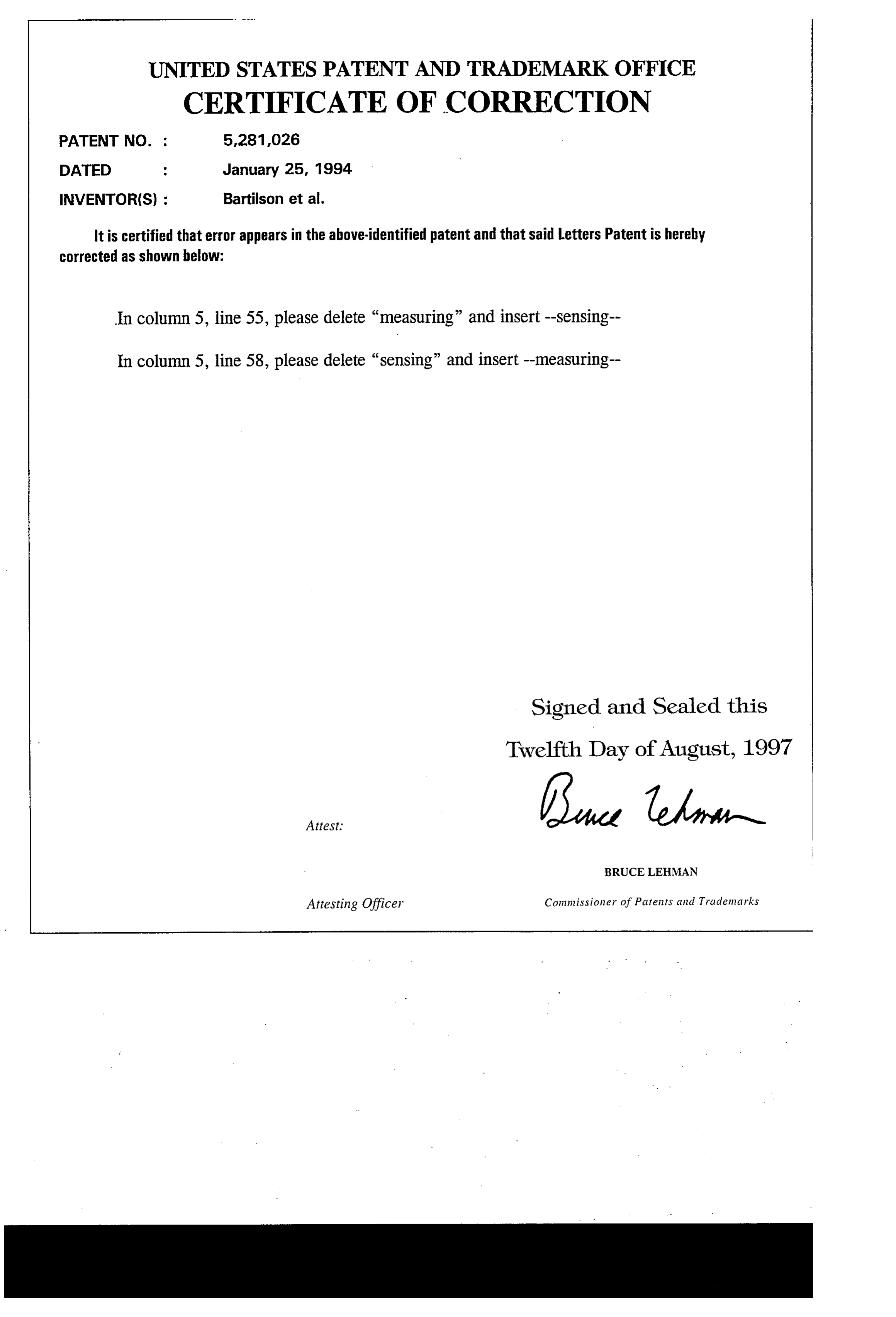
It is certified that error appears in the above-identified patent and that said letters Patent is hereby corrected as shown below:
In column 5, line 55, please delete "measuring” and insert-sensing-- In column 5, line 58, please delete “sensing” and insert-measuring Signed and Sealed this
Twelfth Day of August, 1997
BRUCE LEHMAN
Attesting Officer Commissioner of Patents and Trademarks
Provenance
- Collection
- Cited prior art
- Original PDF
- patentimages.storage.googleapis.com →
- Filed
- 1993-05-03
- Pages
- 11
- Method
- pdftotext (the PDF's own text layer) + pdftoppm 300dpi page scans
- Source
- Google Patents bibliographic record
- Granted
- 1994-01-25
- Inventors
- Bradley W. Bartilson; Elliot F. Schlimme; Cray Research LLC
- Transcribed from
- patentimages.storage.googleapis.com →