patent · US5272879
Multi-system power generator
28 December 1993
Page 1 — bibliographic record
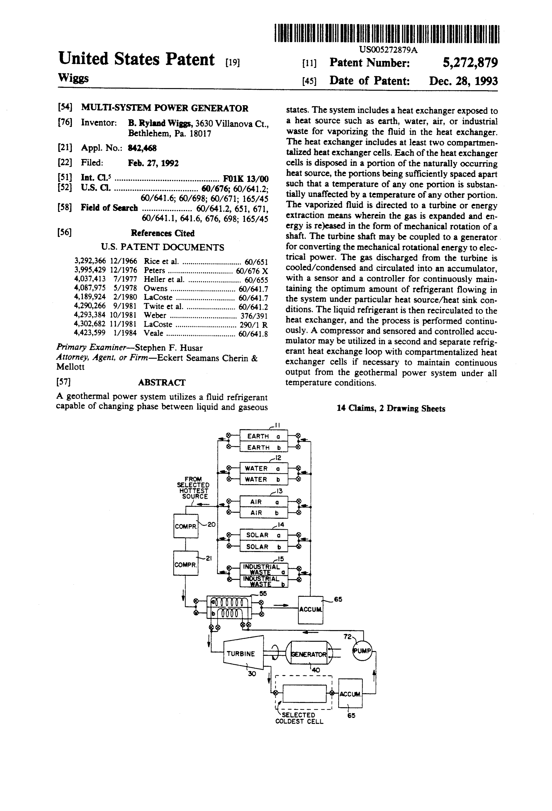
United States Patent (19) 11 Patent Number: 5,272,879 Wiggs 45 Date of Patent: Dec. 28, 1993 (54) MULTI-SYSTEM POWER GENERATOR states. The system includes a heat exchanger exposed to 76) Inventor: B. Ryland Wiggs, 3630 Villanova Ct., a heat source such as earth, water, air, or industrial Bethlehem, Pa. 18017 waste for vaporizing the fluid in the heat exchanger. (21) Appl. No.: 842,468 The heat exchanger includes at least two compartmen talized heat exchanger cells. Each of the heat exchanger 22 Filed: Feb. 27, 1992 cells is disposed in a portion of the naturally occurring 51) int. Cl............................................... FO1K 13/00 heat source, the portions being sufficiently spaced apart 52 U.S. C. ..................................... 60/676; 60/641.2; such that a temperature of any one portion is substan 60/641.6; 60/698; 60/671; 165/45 tially unaffected by a temperature of any other portion. 58) Field of Search ...................... 60/641.2, 651, 671, The vaporized fluid is directed to a turbine or energy 60/641.1, 641.6, 676, 698; 165/45 extraction means wherein the gas is expanded and en
ergy is re)eased in the form of mechanical rotation of a shaft. The turbine shaft may be coupled to a generator.
3,292,366 12/1966 Rice et al. ............................. 60/65 trical power. The gas discharged from the turbine is 3,995,429 12/1976 Peters ......... ... 60/676 X cooled/condensed and circulated into an accumulator, 4,037,413 7/1977 Heller et al. .......................... 60/655 with a sensor and a controller for continuously main 4,087,975 5/1978 Owens ........ ... 60/641.7 taining the optimum amount of refrigerant flowing in 4,189,924 2/1980 LaCoste ............................. 60/641.7 the system under particular heat source/heat sink con 4,290,266 9/1981 Twite et al. ... 60/641.2 ditions. The liquid refrigerant is then recirculated to the 4,293,384 10/1981 Weber ................................. 376/391 4,302,682 11/1981 LaCoste .............................. 290/1 R heat exchanger, and the process is performed continu 4,423,599 1/1984 Veale .................................. 60/641.8 ously. A compressor and sensored and controlled accu Primary Examiner-Stephen F. Husar mulator may be utilized in a second and separate refrig Attorney, Agent, or Firm-Eckert Seamans Cherin & erant heat exchange loop with compartmentalized heat Mellott exchanger cells if necessary to maintain continuous output from the geothermal power system under all 57 ABSTRACT temperature conditions.
A geothermal power system utilizes a fluid refrigerant capable of changing phase between liquid and gaseous 14 Claims, 2 Drawing Sheets
froM
SELECTED
HOTTest
SOURCE
Giere
CODEST CELL
Page 2
Drawing sheet — no readable text.
Page 3
Drawing sheet — no readable text.
Page 4
heat or sink heat between the building and the outside
MULT-SYSTEM POWER GENERATOR heat exchanger, using electrically powered fans and pumps.
BACKGROUND OF THE INVENTION Known systems for tapping the ever abundant heat 1. Field of the Invention source of the earth below the surface, for the purpose of The invention relates to a power generation system generating power, typically convert water into steam which utilizes naturally occurring low grade heat en for driving a turbine or operating a refrigeration plant. ergy at or near the earth's surface to produce mechani For example, see U.S. Pat. Nos. 4,091,623; 4,142,108; cal or electrical power. 4,189,923; 4,255,933; and 4,388,807. The systems require O passages leading deep into the earth. Drilling expenses, 2. Prior Art
Systems for generating power convert the thermal passage obstruction problems, shifting of the earth asso energy difference between a heat source and a heat sink ciated with volcanic activity, and other expenses or to useful power by driving a generator or other power technological problems generally render these ostensi output while transferring heat energy from the source bly good ideas economically unrealistic and infeasible. to the sink. Such systems are most efficient where the 5 Power generation systems have also been developed difference in the temperature between the source and to utilize temperature differentials due to the cooling of sink is the greatest. Geothermal power generation sys ocean water at depth, or as provided due to prevailing tems are known which rely on heat from high tempera currents. Generally, ocean water near the surface, ture sources, located in an area of volcanic activity which is warmed by the sun, provides the heat source, and/or far below the earth's surface, generally at depths 20 and colder deeper ocean water provides a significantly of from 100 to 30,000 feet. The heat is extracted from cooler temperature differential, enabling the generation maqma or superheated rock, and carried to the surface of mechanical and electrical power. See, for example, by water, brine, etc. The heat is then extracted at the U.S. Pat. Nos. 4,087,975; 4,189,924; and 4,302,682. Oce surface, and various uses can be made of the heat, in anic thermal difference energy conversion systems are cluding operating a turbine or other device coupled to 25 an electric generator. Whereas the surface temperature theoretically their attractive for generating power, however application is obviously limited to ocean areas and is always lower than such high temperature sources, the the cooler-side heat exchanger must be very deep to heat extraction technique can be used to generate obtain a substantial temperature difference compared to power.
A power generation system of this type may use a 30 the surface temperature. As with the deep well geother mal systems, from a practical standpoint these proposed circulating coolant which is changed between a liquid power generation systems are quite large, as considered phase and a gas phase in each pass around the circula necessary to be economically feasible in many applica tion loop, the changes being a result of the temperatures encountered at the source and at the sink. For example, tions. Also, major potential problems remain, including pressurized liquid coolant is heated and phase changed 35 weather problems (e.g., hurricanes and typhoons), tides, into a gas on the hotter side of a circulation loop, and shipping traffic, barnacles, corrosion due to long-term after driving a turbine-generator or the like at which the exposure to sea water, etc.
heated coolant is allowed to expand and cool, the now In U.S. Pat. No. 4,290,266, a coolant or refrigerant gaseous coolant is condensed and depressurized to the line is placed sufficiently deep for geothermal heat to liquid phase on the cooler side of the circulation loop, convert gravity drained liquid refrigerant into a gas proceeding again around the loop to the hotter side. under high pressure for use in driving a turbine. The The coolant is circulated continuously around the loop, concept of using a phase changing coolant or refriger generally using the temperature difference between the ant other than water is the same as that of changing hotter and cooler sides as the power source for driving water into steam and back for driving a turbine in a the turbine. 45 geothermal system. However, the refrigerant is nor Apart from direct association with volcanic activity, mally chosen such that it has a boiling point suitable for the underground temperature of the earth near the sur the temperature levels of the system design and thus is face, where insulated from day to day surface tempera readily changed in phase by the temperatures encoun ture variations, is a relatively stable temperature in the tered on the hotter and cooler sides of the loop. On the mid 50 Fahrenheit range. However, at any particular 50 other hand, the refrigerant concept has significant oper time of the year the temperature at the surface, specifi ational problems when one attempts to apply it to geo cally the surface air temperature, may be higher or thermal power generation due to the requirement for lower than the temperature of the earth beneath the substantial vertical conduit lengths between the surface surface. The earth's underground temperature also in and the subsurface heat exchangers. For example, there creases roughly 88 Fahrenheit per mile of depth. 55 is no ready means to force the refrigerant dependably It is known to use the temperature difference between under power around the circulation loop, due to the a heat source or sink at a temperature nearly equal to phase differences between the heavier and less com the surface air temperature to move heat energy into or pressible liquid and the lighter and more-compressible out of a building or other heating/cooling load, by use gas phases. Once gravity fed liquid refrigerant is phase of a similar circulating coolant system known as a heat changed into a gas, it is difficult to force it further pump. The coolant is heated (or cooled) at a heat ex downward, because the low density gas tends to rise in changer located outside of a building and the heat is the higher density liquid refrigerant. In short, it is diffi extracted (or the coolant extracts heat) at a heat ex cult to move the refrigerant in a loop to a sufficiently changer disposed in the building, one or both heat ex hot subterranean depth, prior to phase change, for natu changers normally being associated with fans for mov 65 rally producing the pressures needed for significant ing air over the heat exchanging surfaces. Such systems power generation. Once the liquid refrigerant changes do not produce mechanical or electrical energy from phase from a liquid to a gas, the effects of gravity flow the temperature difference. The systems simply extract are substantially diminished. Inasmuch as the most re
Page 5
mote point in the circulation loop may be far below the invention provides a heat exchanger having two or surface, such gravity flow refrigerant systems ulti more compartmentalized heat exchanger cells in mately suffer from poor system equilibrium and periods contact with the naturally occurring heat source for of in operation. Other problems include inability of the vaporizing a liquid refrigerant. The heat exchanger cells system to operate in a reverse direction, inability to are spaced apart, and switchable valves are provided for recover geothermal heat on the heat extraction side selectively controlling refrigerant flow through the after extended operating periods, and typically, high individual cells so that the heat source in the vicinity of costs and associated problems encountered with deep each cell can alternately be given time to naturally wells.
recover heat after being drawn down by refrigerant
Another approach for a refrigerant type power gen 10 vaporization.
eration system is disclosed in U.S. Pat. No. 3,995,429 with means toAn accumulator/dispenser is provided monitor and control refrigerant quanti
(Peters). This patent describes the production of a pres ties in the system in order surized vapor via selective utilization of temperature temperatures and pressurestoand maintain optimum system to prevent dangerous differentials in two of three or more heat sources or system over pressures or underpressures. A supplemen sinks, each of which varies in temperature over time. A 15 tal fluid pump is powered by an electric motor for moving alsodesign utilizing two separate refrigerant loops may be used, with the first loop utilizing a compressor liquid refrigerant around a loop including selected ones for circulating the refrigerant, and for pressurizing and of the sources and sinks. Controls and valves are pro heating the vaporized refrigerant returning from the vided for switching between heat and heat sink sources underground heat source, to a suitable temperature for having the most efficient (highest) naturally occurring 20 temperature differential. The disclosure of the patent ensuring loop for a phase change in the secondary refrigerant operating a turbine, reciprocating engine or teaches heat sources including a solar energy absorber, a radiator placed in the earth or in water, and an atmo other power extraction device which expands the pres spheric heat exchanger. One obvious problem with this surized gas and assists in converting the pressurized system, as noted in the patent, is that under certain 25 refrigerant back into the liquid phase. The turbine or conditions there is no sufficient temperature difference other engine may be coupled to a generator for produc between any two of the heat, or heat sink, sources, ing electricity. Alternatively, it can be used to provide whereupon all action stops. This results in a lack of mechanical power. The mechanical or electrical energy continuous and dependable power. Moreover, refriger can be stored via compression of gas or hydraulic fluids, ant equilibrium problems and imbalances in refrigerant 30 electrolysis, batteries, etc., for later use. Expansion quantities occur and must be accurately and consis valves and condensing cells are provided as necessary tently controlled to effect appropriate refrigerant phase to maintain operational temperature/pressure differen changes under varying load and temperature differen tials in the system. For the system with two separate tial conditions and to effectively generate power. For refrigerant loops wherein the refrigerant in the first example, Peters neglects to provide a means to over 35 loop is continuously circulated by the compressor, the come the negative effects which will operationally be system, unlike Peters, is operational with extremely realized when the vaporized refrigerant encounters modest temperature differentials between the heat pressure resistance from the turbine and exerts a back source and the heat sink.
pressure against and/or into the liquid refrigerant exit The invention is particularly applicable to a ground ing the liquid refrigerant pump and/or source. Such source heat exchanger having temperature exchange back pressure can severely hamper system operational coils which are buried in an array near the earth's sur efficiency, ultimately placing as much of a power drain face, especially just below the frost line or heat line. For on the circulating pump as the turbine is able to produce example, a sinuous pattern of copper or other thermally from the coolant. This back pressure can result in sys conductive tubing can be mounted along the walls of a tem equilibrium loss and shut down. Further, the Peters 45 simple backhoe trench to provide the subsurface heat invention neglects to provide for a coolant ac exchanger. Similarly, a bored cylindrical hole can be cumulator/dispenser system which will automatically lined with a helical pattern of heat exchange coils, sense conditions and adjust the amount of refrigerant rested along the sides of the hole before backfilling. The contained in the circulation loop at any given time to subsurface heat exchanger can be operated in conjunc maintain optimum conditions for the particular heat 50 tion with heat exchangers for the opposite side of the source/heat sink system being utilized for power gener loop, including water based and ambient air heat ex ation. Such a refrigerant supply control is critical for changers, thus providing a versatile system for extract optimum system operation under varying temperature ing power from naturally occurring temperature differ conditions. For example, when operating under rela ences. The apparatus can be provided simply as a power tively colder temperature conditions, a larger quantity 55 generation device, or alternatively can be operated in a of refrigerant is required to achieve optimum perfor power generation mode only when not in use as a build mance than when operating under relatively hotter ing HVAC heat pump system.
temperature conditions. If refrigerant quantities in the system are not controlled and reduced when operating SUMMARY OF THE INVENTION between the warm sun and warm air and/or warm It is an object of the invention to provide a power water and/or warm earth in the summer, as opposed to generation system which is relatively simple to con colder identical heat and heat sink sources in the winter, struct, operate and maintain.
pressures may become so high or so low as to result in It is another object of the invention to provide a pump and/or generator burn out or malfunction. power generation system which is cheaper to construct The present invention overcomes these problems by 65 and operate than conventional systems. providing a geothermal power system and method It is a further object of the invention to provide a which utilizes a low grade, naturally occurring heat power generation system which can be built on either a source found at or near the surface of the earth. The small or large scale at almost any location.
Page 6
It is yet another object of the invention to provide a The compressor is a beneficial part of the invention. power generation system which efficiently provides The compressor maintains refrigerant flow in the sys mechanical or electrical power with little or no damage tem even during periods of low temperature differen to the environment. tials, thereby overcoming the problem of the prior art It is still another object of the invention to provide a systems which become inoperative in the event of low power generation system which utilizes naturally oc temperature differentials. Further, refrigerant flow is curring heat sources having relatively small tempera maintained at a sufficient velocity to prevent separation ture differentials. of lubricating oil out of suspension in the refrigerant. These and other objects are accomplished by a power The compressor also provides a means of condensing generation system which utilizes a refrigerant fluid suit 10 and accelerating the effects of even modest temperature able for changing phase between liquid and gaseous differentials, thus enabling the system to operate to take states. In the first design, a heat exchanger absorbs heat advantage of whatever temperature differences are from a low grade, naturally occurring heat source such available even when the differences are relatively small. as shallow earth, shallow water, air, solar or industrial waste heat. The heat exchanger includes two or more 15 BRIEF DESCRIPTION OF THE DRAWINGS heat exchanger cells and selector valves for controlling There are shown in the drawings the embodiments of refrigerant flow through each cell. The cells in any one the invention that are presently preferred. It should be naturally occurring heat source are sufficiently spaced understood, however, that the invention is not limited apart so that each cell draws down heat from its local 20 to the precise arrangements and instrumentalities shown area with negligible effect on the heat content of the in the drawings, wherein:
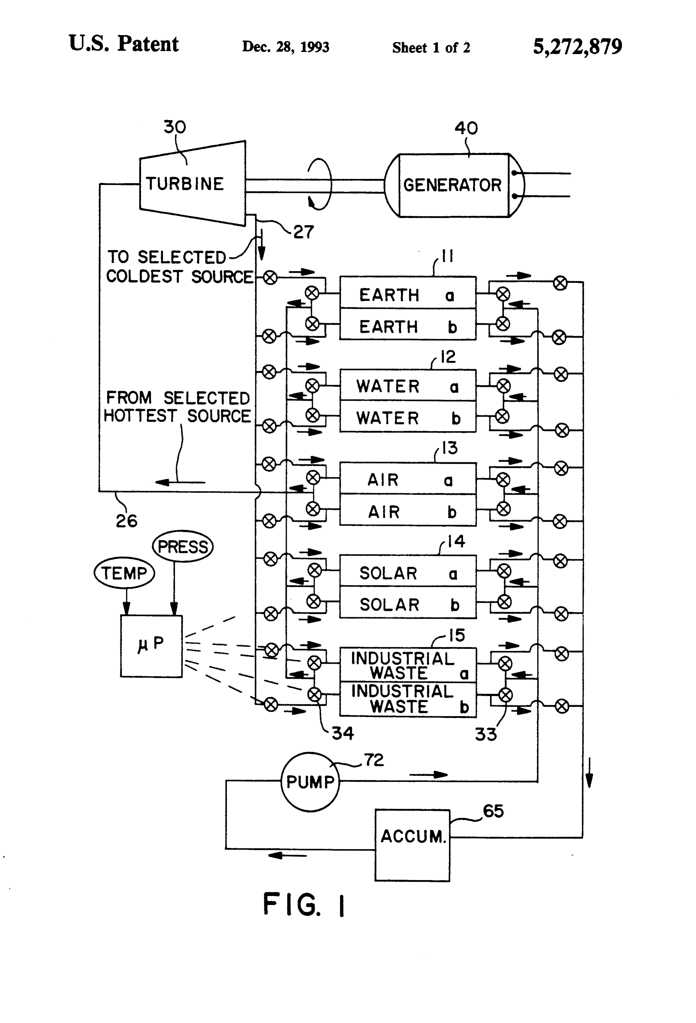
local area of any other cell. The individual heat absorp FIG. 1 is a schematic view illustrating an exemplary tion cells are permitted appropriate time to recover heat embodiment of the power generation system according and gasify the liquid refregerant in them by shutting off to the invention.
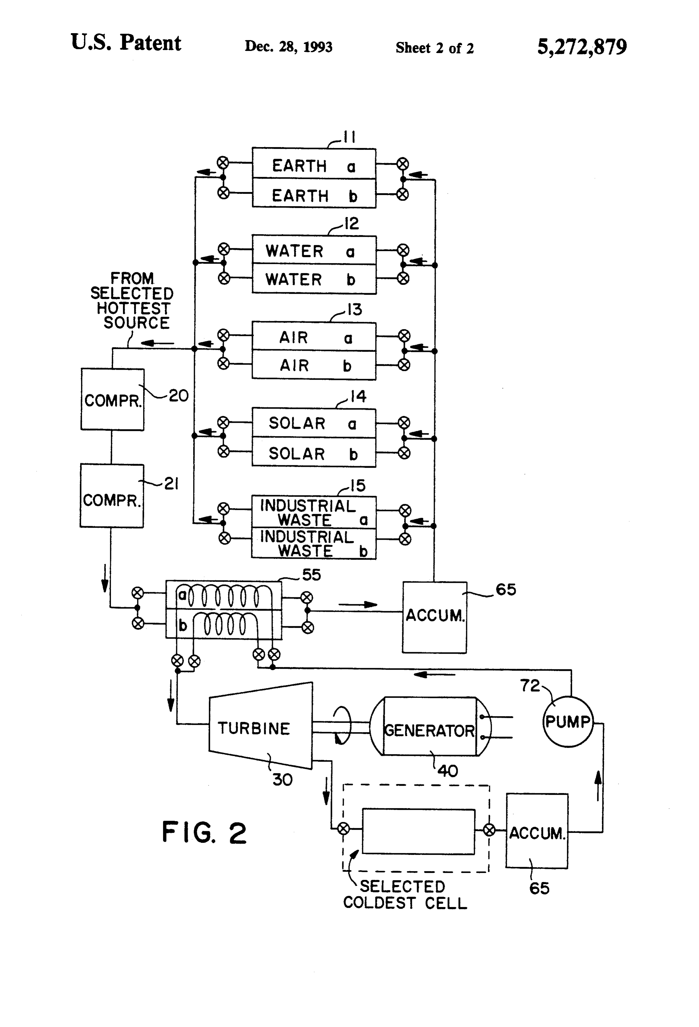
and isolating the liquid refrigerant supply and the gase 25 FIG. 2 is a schematic view illustrating an alternative ous discharge until sufficient gas pressure is reached. embodiment of the power generation system according The liquid refrigerant passes into one of the heat ex to the invention.
changer cells and is vaporized into a pressurized gas. DETAILED DESCRIPTION OF THE Once sufficient gas pressure is reached, a valve opens PREFERRED EMBODIMENTS and permits the pressurized gas to enter a turbine or 30 A power generation system according to the inven reciprocating engine. The gas is expanded in the tur bine, thereby giving up energy in the form of powered liquid tion utilizes a suitable fluid which changes phase from mechanical rotation of the turbine. The mechanical to gaseous states at relatively modest tempera tures and energy thus developed can be converted to electrical tem as hereinafter at pressures which are maintained in the sys energy in a generator coupled to the turbine and/or 35 chosen to undergo described. In particular the fluid is stored via batteries, electrolysis, hydraulic or pneumatic at the temperaturesa liquid to gas phase change readily encountered in a heat exchanger fluids or gases, potential energy (e.g. by lifting a quan disposed in contact with a low grade, naturally occur tity of water), etc., for later use. After exhausting from ring or waste heat source, and is pressurized according the turbine, the expanded gas would be converted to a to the invention such that the phase change from liquid liquid in a condenser, which condenser can comprise to gas occurs at a point in the circulation loop where the one or more of the coolest compartmentalized heat phase change can be used to drive a mechanical means exchange cells, to maintain system operating parame for extracting energy, i.e., at a turbine or other engine ters. The liquid is then circulated back to the heat ex which extracts mechanical energy by allowing pressur changer and the process is repeated. A pump may be ized gas to expand to a larger volume. The gas may be provided for maintaining the liquid refrigerant flow to 45 a commonly used refrigerant such as Freon 12 or Freon the heat exchanger cells A liquid refrigerant accumula 22, or ammonia, or another known refrigerant. The tor and control means such as valves are provided for fluid is communicated directing the quantity and flow of the refrigerant duit means such as pipethroughout or tubing the system by con connected between through the system at optimum quantities, temperatures successive stages in the system.
and pressures. Preferably the valves are solenoid valves 50 According to a first embodiment of the invention, coupled to outputs of a microprocessor controller one or more heat exchangers is disposed in thermal which is also coupled to temperature and pressure sen communication with a heat source. As illustrated sche sors along the circulation path, and programmed to matically in FIG. 1, heat exchangers 11, 12, 13, 14, 15 optimize system parameters by controlling the valves are disposed in thermal communication with a naturally and refrigerant supply as appropriate to present sensed 55 occurring or waste heat source such as geothermal, conditions.
water, air, solar energy, or an industrial waste heat
A secondary design utilizes two separate refrigerant source, respectively. The, for example, geothermal heat loops. The first loop utilizes a compressor for circulat exchanger should be placed sufficiently below the ing the refrigerant through a condensing cell, which earth's surface to provide a dependable source of heat at cools and liquifies the refrigerant, and through a heat least at the typical subsurface temperature of 55' F., and source which heats and vaporizes the refrigerant. The compressor pressurizes and superheats the gaseous where available may be placed in thermal communica tion with a warmer temperature source.
phase-changed gas exiting the heating source. The sec According to the invention, the heat exchangers 11, ond loop operates in the manner as described herein 12, 13, 14, 15 need not be, but could be, in thermal above in the first design, except the heat source for the 65 communication with a high temperature heat source. second power generation loop is the heat generated via The invention can utilize heat retained in shallow earth, the first refrigerant loop achieving refrigerant circula shallow water, air or other substance at moderate tem tion by means of a compressor. peratures. For example, the geothermal heat exchanger
Page 7
11 preferably comprises a plurality of substantially hori sensors and valve actuators. As shown generally in zontal tubes disposed in the earth at a distance of one or FIG. 1, control valves 33, 34 are provided at the inlet two feet below the frost line for the geographic locality and outlet of each of the heat exchanger cells to selec of the system, in order to minimize the depth of excava tively arrange the fluid circulation loop to include tion required for subterranean placement of the heat whichever of the heat exchanger cells will provide the exchanger while preventing the tendency of the tubes greatest heat source, as determined by the sensing and to become displaced due to frost heaving or to become control means. This valving arrangement can direct the inefficient due to proximity to cold surface conditions. fluid to traverse more than one of the heat exchanger A suitable heat exchanger is disclosed in patent applica cells, for example to take advantage of the possibility tion Ser. No. 725,962, filed Jul. 5, 1991, entitled MOD 10 that more than one of the heat exchanger cells is at a ULAR TUBE BUNDLE HEAT EXCHANGER usefully tapped temperature.
AND GEOTHERMAL HEAT PUMP SYSTEM, The refrigerant fluid is maintained within the respec hereby incorporated by reference. Alternatively, the tive heat exchanger cells a, b where it receives heat heat exchanger may be disposed in shallow water or in from the heat source portion in which the heat ex air, or exposed to heat from solar energy or industrial 15 changer cell is in thermal communication. The refriger waste heat, provided the heat exchanger is disposed to ant in the respective heat exchanger cells is changed be heated relative to the temperature of the expanded into its gaseous phase and, once a sufficient pressure is (cooled) refrigerant which has been passed through the reached, the pressurized refrigerant gas opens a pres turbine or other mechanical energy extraction means. sure valve, or is released from the cells via timed se Only modest temperatures are required for operation of 20 quence valves or a pressure sensor. The individual, the system according to the invention, however, it is compartmentalized heat exchanger cells provide the advantageous to employ the maximum temperature advantage of permitting retention of the refrigerant in differential which is available, for best efficiency. one cell so that it has time to absorb sufficient heat to Each of the heat exchangers includes at least two vaporize and pressurize the refrigerant completely, compartmentalized heat exchanger cells designated a 25 while simultaneously permitting release of the refriger and b and placed in different locations having poten ant which has been vaporized and pressurized in an tially different temperatures. The different locations can other cell so that pressurized refrigerant is kept avail be in different portions of one source of heat, the por able for operating a turbine means as hereinafter de tions being sufficiently spaced apart that a temperature scribed. The individual compartmentalized heat ex of any one portion is not substantially affected by a 30 changer cells further provide the advantage of eliminat temperature of any other portion. Thus, the cooler fluid ing back pressure against and/or into the liquid refriger refrigerant flowing into one of the heat exchanger cells ant and against a liquid refrigerant pump hereinafter draws heat from the portion of the heat source associ described, which back pressure would otherwise sub ated with that cell, but does not draw down any sub stantially undermine system operational efficiency and stantial amount of heat from the portion of the heat 35 /or result in system equilibrium loss and shutdown. source associated with any other cell in the heat source The vaporized refrigerant flows through conduit 26 as a whole. The use of spaced apart heat compartmen to a turbine means such as turbine 30, or any other talized heat exchanger cells allows the refrigerant to be rotary, reciprocating, stirling, inertial or scroll engine. contained in one of the cells for a time sufficient to In the presently preferred turbine embodiment, the gas permit complete vaporization and appropriate pressur is directed through nozzles to impinge on a plurality of ization of the refrigerant in the one cell while allowing blades connected to a rotatable shaft. The gas acting on the other cell time to discharge its already heated and the blades is expanded at the nozzles and energy pressurized gas into the turbine 30. Temperature sensing thereby extracted from the pressurized gas is converted means associated with each of the heat exchanger cells into rotational (mechanical) energy of the turbine shaft. 11,12,13,14,15 are coupled to a control device which 45 The shaft may be coupled to any apparatus which can senses the temperature for each portion of the heat appropriately utilize the mechanical energy, and prefer source having a heat exchanger cell. The control de ably is arranged to store the energy by mechanical, vice, which may comprise a programmed microproces electrical or chemical means. For example, the shaft sor coupled to sensors associated with the respective may be coupled to an electric generator means 40 for heat sources or portions, determines the temperatures SO generating electrical power, which can be utilized by available and chooses the highest temperature and coupling to the electric mains via an inverter, or stored greatest temperature differential of the respective heat in batteries. The system may be operated for electrical source portions. Via controllable valves coupled to the power generation via direct current generation and/or circulation passages the control device selects and via alternating current generation, with constant output switches the circulation loop to traverse one or more of 55 and/or turbine speed and/or generator load maintained the available heat exchanger cells. In this manner the via use of an eddy current clutch and/or via controlling control device avails the system of the particular heat areas exposed to the low grade heat source and/or via source portion which has the greatest heat reserve and introduction of pressurized gas in subatmospheric oper /or the greatest capacity and highest difference in tem ation. The mechanical or electrical power can be also be perature. U.S. Pat. No. 3,995,429 to Peters discloses a used or stored, for example, by raising a fluid or other suitable sensing means and switching means for select weight, by pressurizing a reservoir, by electrolysis, etc. ing among different heat sources, and the disclosure is After expansion and energy extraction, the refriger hereby incorporated for the particulars of sensing and ant gas is circulated back through conduit 27 to one of control arrangements which can select among plural the heat exchangers 11, 12, 13, 14, 15 acting as a con sources to obtain the greatest available thermal energy 65. denser in a relatively cooler one of the potential heat difference. It is also possible to arrange a similar func sources which now acts as a heat sink. The control tion using, for example, other mechanical controls and valves 33, 34 are operated by the sensing and control /or a microprocessor coupled to suitable temperature device to admit the refrigerant gas to whichever of the
Page 8
heat exchangers is disposed in the greatest and coldest The compressor means may include, e.g., a reciprocal, heat sink source. The refrigerant is cooled and liquified scroll, rotary, or inertial type compressor. The com in the heat exchanger acting as the condenser, thereby pressor means not only moves the gas and the liquid reducing the pressure in the coolant conduit 27 on the refrigerant in the first loop, independently of gravity downstream side of the turbine or other engine. If nec and/or independently of a liquid pump 72, as contained essary, the refrigerant gas could be isolated and main in the second loop, but more importantly, it provides a tained in the compartmentalized heat exchanger cells means of condensing and accelerating the effects of for a period of time so that excessive heat would have even modest renewable temperature differentials. Con adequate time to be removed in each cooling cell, for sequently, it is not necessary to wait for or to rely only reducing the pressure in this area of the loop. O upon naturally occurring significant temperature differ After release from the condenser, the liquid refriger entials. Instead, continuous power is provided via the ant flows to an accumulator/dispenser 65 having means much more dependable modest temperature differen for sensing and adjusting an optimum amount of liquid tials existing due to various thermal energy situations refrigerant in the system. The refrigerant released from which are virtually always readily available. A modest the accumulator/dispenser 65 is pumped via liquid re 15 but dependable thermal differential exists, for example, frigerant pump 72 back into whichever of the heat ex between the earth in one's yard and the atmosphere changers is disposed in the greatest heat source, as de directly above it. Various industrial processes produce termined by the sensing and control device, and the modest but dependable thermal temperature differen process is repeated. Thus, the power generation system tials between gaseous or fluid effluent and the ambient according to the invention comprises numerous poten air or water. These sources/sinks can be exploited ac tial refrigerant loops for generating mechanical or elec cording to the invention, or the invention may be ap trical energy, with sensing, control and valve means for plied to exploit the temperature difference between any circulating refrigerant through an active loop which two appropriate heat sources and sinks which can be includes the isolated and compartmentalized heat ex placed in thermal communication with a heat ex changers disposed in the greatest heat source and the 25 changer.
greatest heat sink at any given time. The compressor means may include a plurality of The liquid refrigerant accumulator/dispenser 65 is serially coupled compressors 20 and 21 in order to used for automatically sensing and adjusting, via me achieve a sufficiently high gas temperature differential chanical controls and preferably via a procedure of for optimum performance of the mechanical energy calculations or parameter look-up functions supervised extraction means, which in the preferred embodiment by a micro-processor, the proper amount of refrigerant comprises a gas turbine. While it would be desirable to to be utilized at any given time under the particular utilize only one compressor in order to avoid efficiency refrigerant supply/pressure requirements necessitated losses occasioned by additional compressor units, more via the particular temperature differentials and pressure than one compressor may be utilized when marginal conditions existing between the particular heat source/- 35 conditions require that the pressure and/or temperature heat sink portions selected as active at the time. Absent condition of the compressed gas be stepped up via sec continuous and correct adjustment of the refrigerant ondary or secondary and tertiary compressors, etc. A supply to the active loop, based upon actual operational single compressor may raise the pressure of the refriger temperature differentials, it is difficult or impossible to ant by an amount equivalent to raising the refrigerant achieve efficient, or even actual, refrigerant phase temperature as compared to the output of the naturally change, as needed to optimize operational efficiency. occurring heat source gas temperatures by 100" F., or The power generation system may be microprocessor more. When higher gas temperatures are necessary to controlled to achieve optimum temperatures and pres effectively operate the turbine or the like, the initially sures for best system efficiency. A flash evaporating compressed gas may be stepped up to a second higher system, with a subatmospheric pressure range turbine, 45 temperature/pressure condition via a next compressor, may be utilized to optimize performance below atmo and to a third compressor, and so on, as necessary. The spheric pressures. Whereas the system operates by pro gas discharged from the compressor means, if from an viding a phase change in the refrigerant between the earth source, will typically have a temperature between hotter and cooler sides of the circulation loop, together approximately 120 and 200' F., and a pressure between with stepping up the pressure of the refrigerant gas SO approximately 200 and 325 PSI.
preceding the mechanical energy extraction means, it is Two or more compartmentalized heat exchanger possible selectively to operate the system at different cells are preferably alternately used with the compres points in the pressure/temperature/phase chart which sor means in the first closed loop so as to allow respec characterizes the particular coolant chosen. tive cell heat recovery time when the system is in con According to a second embodiment of the invention 55 tinuous operation. Sensors and valves automatically as shown in FIG. 2, two separate refrigerant circulation control refrigerant flow through the respective heat loops are provided. Like elements of the first and sec exchanger cells. Additionally, as in the power genera ond embodiments are referred to in the drawings by like tion system of the first embodiment, a controlled liquid reference numbers. In the first loop of the second em accumulator/dispenser 65 automatically adjusts the bodiment, the refrigerant gas exiting at least one se optimum amount of refrigerant flowing through the lected heat exchanger 11, 12, 13, 14 or 15 flows to a first loop refrigerant system.
compressor means 20. The gas enters the compressor The compressed and superheated refrigerant gas in means at a temperature, for example, if from an earth this first closed loop system, which contains the heat heating source, between approximately 25 and 60' F. energy acquired from the sun, the air, or from a ground and at a pressure between about 50 and 100 pounds per 65 or water mass, or from industrial waste heat or other square inch (PSI). The compressor means compresses source, as aforesaid, transfers the accentuated heat en the gas and raises its temperature such that the gas dis ergy to a separate and second closed loop refrigerant charged from the compressor is slightly superheated. system via thermal coupling means such as an isolated
Page 9
and compartmentalized a b refrigerant to refrigerant a "hot' refrigerant tube from one of the systems, carry heat exchange coil 55. This method of heat energy ing extra and/or waste heat, coiled around another tube transfer eliminates efficiency destructive back pressure with cooled refrigerant from the other system Which on the compressor in the first loop. The exchange coil cooled refrigerant is in sequence to absorb heat and 55 includes separate pathways for the refrigerant in the expand. The refrigerant to refrigerant heat exchange first and second loops, such as two tubes spiraled coil could also consist of a tube, with refrigerant from around each other in direct contact, or one tube con one system, within another tube, with refrigerant from taining the hot gas exiting the compressor of the first the other system, in order to accomplish the same heat loop disposed within a separate tube containing cooler exchange step.
liquid refrigerant of the second loop. In the exchange 10 Sensors and mechanical and/or microprocessor con coil 55, heat is transferred from the hot refrigerant gas trols preferably are coupled to each of the respective exiting the compressor in the first closed loop system to circulation paths, to monitor and control proper heat the cooler liquid refrigerant in the second closed loop exchange between the two systems such that each sys system, which refrigerant in the second loop, when tem operates at the maximum available efficiency under heated and vaporized to become a pressurized gas, 15 varying ambient conditions for each of the heat ex drives the turbine or other motor means 30 so as to changers.
create mechanical power, which can be used to drive For the geothermal power system having a heat ex the electrical generator 40. At least one of the cells changer disposed in water or in the air, the heat ex defining a selected coldest source is controllable cou changer could include tubing, or rifled tubing, having pled into the conduit on the downstream side of the 20 internal or external fins for maximizing heat transfer. turbine. Such a heat exchanger could be relatively smaller than A power generation system according to the inven a heat exchanger having the same capacity which is tion, whether a single refrigerant loop (as in the first disposed in earth, due to the added factors of improved embodiment) or a double refrigerant loop (e.g., the thermal transfer and the existence of convection cur second embodiment), can operate in conjunction with a 25 rents in the water.
ground source heating/cooling system which is either a Individual tubes of the heat exchangers 11, 12, 13, 14, water-based or direct refrigerant exchange type system. 15 and the heat exchange coils 55 are generally con Such a ground source heating/cooling system is de structed of copper or aluminum or some similar highly scribed in U.S. Pat. No. 5,025,634, which is hereby conductive metal or plastic or material. Copper, how incorporated by reference. The invention can either 30 ever, when placed in soil or water, is subject to corro operate independently in a separate parcel of land, or sion in the form of oxidation. The chemical reaction immediately adjacent to, or in close proximity with the behind the oxidation of a metal, such as copper, in heat exchange coils of a ground source heating/cooling volves a loss of electrons from the metal. To prevent a HVAC system, especially in warm climates. Further loss of electrons from the tubes of the heat exchangers more, the system can employ at least one of the heat 35 and heat exchange coils, cathodic protection may be exchangers of an HVAC system when not in use. provided. The cathodic protection method as known in Where power generation system heat exchangers and the art involves a sacrificial anode which is electrically heating/cooling system heat exchangers are located in coupled directly to a tube in each of the heat exchangers close proximity to one another (typically immediately and heat exchange coils. In a chemical reaction between adjacent to one another or within a two foot distance of 40 the copper tubes, the sacrificial anode, and the soil or one another), the two separate systems preferably oper water, the sacrificial anode releases electrons which ate in a reverse fluid flow arrangement one from the travel to the copper tubing through a wire or other other. This allows each of the systems to supplement electrical coupling device. The copper tubing emits the other system's efficiency by adding to the tempera electrons to the soil or water which acts as an electron ture differentials encountered. For example, in a warm 45 sink. The copper, although losing electrons to the soil climate, a ground source air conditioning system ex or water, is continuously supplied with electrons from tracts heat from interior air and rejects the heat into the the sacrificial anode. The copper tubing therefore does ground. A power generation system, with a ground not experience a net loss of electrons and hence does not source heat exchanger in close proximity to a ground oxidize and corrode. The sacrificial anode does experi source heat exchanger of the heating/cooling system, 50 ence a net loss of electrons and will oxidize over time, would extract normal ground heat, as well as waste heat but can easily and inexpensively be replaced. dissipated in the ground from the heating/cooling sys The invention having been disclosed, a number of tem, and reject waste heat into exterior air via a conven variations will now become apparent to those skilled in tional exterior air heat exchanger. This process, which the art. Whereas the invention is intended to encompass is a form of recovery of waste heat, also aids the hea 55 the foregoing preferred embodiments as well as a rea ting/cooling ground source heat exchanger in dissipat sonable range of equivalents, reference should be made ing waste heat, which thus does not accumulate as rap to the appended claims rather than the foregoing discus idly in the ground. Operation of the power generation sion of examples, in order to assess the scope of the aspects of the invention thereby can assist in air condi invention in which exclusive rights are claimed. tioning efficiency. I claim:
Further, in lieu of placing ground based heat ex 1. A power generation system of the type having a change coils from the heating/cooling system in close refrigerant fluid suitable for changing phase between proximity to the ground based heat exchange coils in liquid and gaseous states, comprising: the power generation system, the excess heat from the heating or vaporizing means for transferring heat to heating/cooling system could be conveyed to the 65 the fluid from at least one heat source, the heating power generation system, or vice versa, via a direct or vaporizing means including at least two com heat refrigerant to refrigerant exchange coil. The refrig partmentalized heating or vaporizing heat ex erant to refrigerant heat exchange coil would comprise changer cells, each of the heating or vaporizing
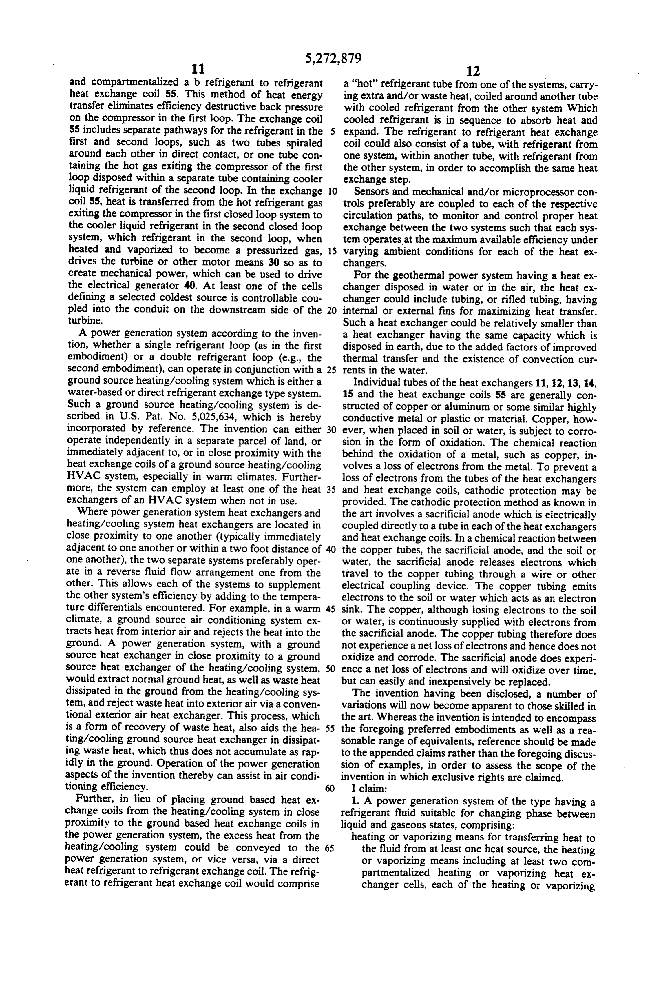
Page 10
heat exchanger cells having a heat conductive con source, the heating or vaporizing means includ struction and defining a controlled inlet, a con ing at least two compartmentalized heating or trolled outlet, and a passageway for refrigerant, vaporizing heat exchanger cells, each of the each of the heating or vaporizing heat exchanger heating or vaporizing heat exchanger cells hav cells being disposed in a portion of the at least one ing a heat conductive construction and defining heat source, the fluid in the heating or vaporizing a controlled inlet, a controlled outlet, and a pas means being changed in phase from a liquid to a sageway for refrigerant, each of the heating or gas, vaporizing heat exchanger cells being disposed energy extraction means for extracting mechanical in a portion of the at least one heat source, the energy from the gas; 10 portions being sufficiently spaced apart such that cooling or condensing means located in at least one a temperature of any one portion is substantially cooling source for converting the refrigerant gas to unaffected by a temperature of any other por a liquid, the cooling or condensing means including tion, the first refrigerant fluid in the heating or at least two compartmentalized cooling or con vaporizing means being changed in phase from a densing heat exchanger cells, each of the cooling or 15 liquid to a gas;
condensing heat exchanger cells having a heat control valve means operable for selectively direct conductive construction and defining a controlled ing the first refrigerant fluid through different inlet, a controlled outlet, and a passageway for ones of the heating or vaporizing heat exchanger refrigerant, each cooling or condensing heat ex cells;
changer cells being disposed in a portion of the at compressor means for pressurizing, heating, and least one cooling source, the fluid in the cooling or circulating the first refrigerant gas; condensing means being changed in phase from a a first pathway in the thermal coupling means gas to a liquid;
accumulator means for holding and adjusting a vol wherein the first refrigerant gas transfers heat to ume of fluid in the system; 25 the second refrigerant fluid; pressure control means for preventing flow of the accumulator means for holding and adjusting a refrigerant gas between the energy extraction volume of the first refrigerant fluid circulating in means and at least one of the cells of the heat ex the first refrigerant loop; and, changer means, until refrigerant gas in the respec conduit means for communicating the first refriger tive said cell reaches a pre-selected pressure; 30 ant fluid between successive stages in the first pump means for circulating the fluid in the system; refrigerant loop such that the first refrigerant control valve mans associated with at least one of said fluid is routed successively through the heating controlled inlets of the heat exchanger cells and or vaporizing means, compressor means, thermal controlled outlets of the heat exchanger cells for coupling means, condenser means, and accumu selectively directing the refrigerant through differ 35 lator means;
ent ones of the heat exchanger cells; and, the second refrigerant loop including: conduit means for communicating the fluid between pump means for circulating the second refrigerant successive stages in the system such that the fluid is fluid in the second refrigerant loop; routed successively through the heating or vapor a second pathway in the thermal coupling means izing means, energy extraction means, cooling or wherein the second refrigerant fluid is changed condensing means, accumulator means and pump in phase from a liquid to a gas; e3S. energy extraction means for extracting mechanical 2. The system according to claim 1, wherein the at energy from the second refrigerant gas; least one heat source includes one of earth, water, air, cooling or condensing means located in at least one solar energy and waste heat. 45 cooling source for converting the refrigerant gas 3. The system according to claim 1, wherein the en to a liquid, the cooling or condensing means ergy extraction means is operatively coupled to a gener including at least two compartmentalized cool ator means for producing electrical power. ing or condensing heat exchanger cells, each of 4. The system according to claim 1, wherein the en the cooling or condensing heat exchanger cells ergy extraction means includes one of a turbine engine, SO having a heat conductive construction and defin a stirling engine, a scroll engine, a rotary engine, an ing a controlled inlet, a controlled outlet, and a inertial engine, and a reciprocating engine. passageway for refrigerant, each of the cooling 5. The system according to claim 1, further compris or condensing heat exchange cells being dis ing at least one of hydraulic and pneumatic means oper posed in a portion of the at least one cooling atively coupled to the energy extraction means for stor 55 source, the portions being sufficiently spaced ing energy by compression of at least one of a fluid and apart such that a temperature of any one portion a gas. is substantially unaffected by a temperature of 6. A power generation system of the type having any other portion, the fluid in the cooling or refrigerant fluid suitable for changing phase between condensing heat exchanger means being changed liquid and gaseous states, comprising: in phase from a gas to a liquid; a first refrigerant loop having a first refrigerant fluid; accumulator means for holding and adjusting a a second refrigerant loop having a second refrigerant volume of the second refrigerant fluid circulat fluid; and, ing in the second refrigerant loop; and, thermal coupling means for transferring heat from the conduit means for communicating the second re first refrigerant fluid to the second refrigerant fluid; 65 frigerant fluid between successive stages in the the first refrigerant loop including: second refrigerant loop such that the fluid is heating or vaporizing means for transferring heat routed successively through the pump means, to the first refrigerant fluid form at least one heat thermal coupling means, energy extraction
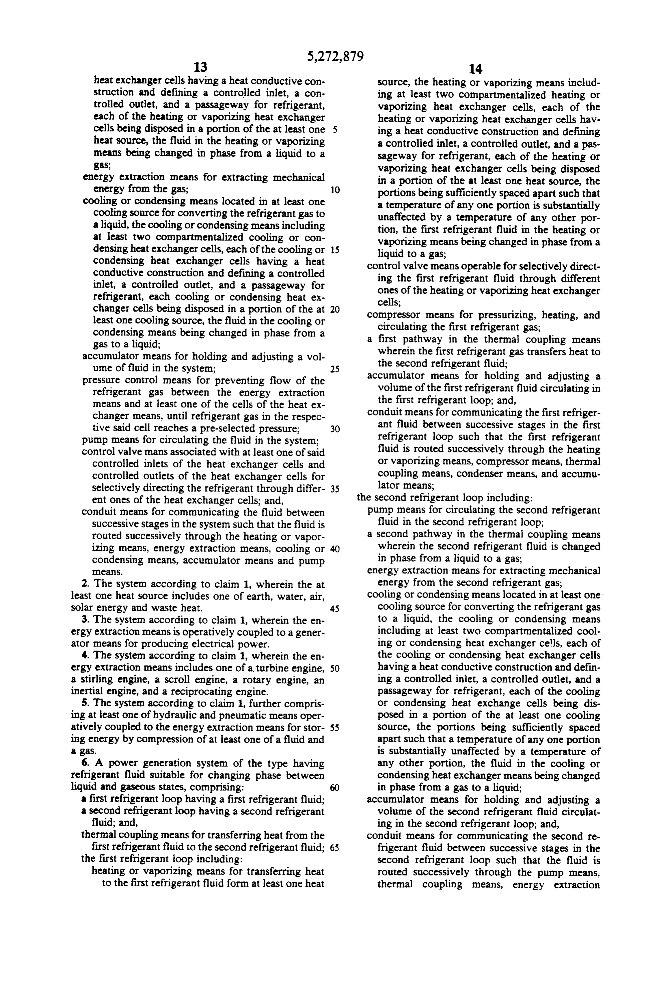
Page 11
means, condensing or cooling means, and accu ing energy by compression of at least one of a fluid and
7. The system according to claim 6, wherein the at energy 11. The system according to claim 6, wherein the extraction means is operatively coupled to gen least one heat source includes one of earth, water, air, erator means for producing electrical power. solar energy and waste heat. 12. The system according to claim 6, wherein the 8. The system according to claim 6, wherein the com energy extraction means includes one of a turbine en pressor means comprises a plurality of compressors gine, reciprocating engine, stirling engine, a scroll en each pressurizing the first refrigerant gas in successive 10 gine,
a rotary engine, and an inertial engine.
The system according to claim 6, wherein the first
Stages, and second pathways in the thermal coupling heating or 9. The system according to claim 6, wherein the com vaporizing means include a pair of tubes spiraled around pressor means includes one of a reciprocal, a scroll, a each other in direct contact.
Stirling, an inertial, and a rotary compressor. 14. The system according to claim 6, wherein the first and second pathways in the thermal coupling heating or 10. The system according to claim 6, further compris 15 vaporizing ing at least one of hydraulic and pneumatic means oper within the other. means include a pair of tubes disposed one atively coupled to the energy extraction means for stor k B k B
Provenance
- Collection
- Cited prior art
- Original PDF
- patentimages.storage.googleapis.com →
- Filed
- 1992-02-27
- Pages
- 11
- Method
- pdftotext (the PDF's own text layer) + pdftoppm 300dpi page scans
- Source
- Google Patents bibliographic record
- Granted
- 1993-12-28
- Inventors
- B. Ryland Wiggs
- Transcribed from
- patentimages.storage.googleapis.com →