patent · US5187377
LED array for emitting light of multiple wavelengths
16 February 1993
Page 1 — bibliographic record
United States Patent (19) 11 Patent Number: 5,187,377 Katoh (45) Date of Patent: Feb. 16, 1993 54 LED ARRAY FOR EMITTING LIGHT OF 5,008,788 4/1991 Palinkas .............................. 362/800 MULTIPLE WAVELENGTHS FOREIGN PATENT DOCUMENTS (75) Inventor: Masaaki Katoh, Osaka, Japan 55-150282 ll/1980 Japan ..................................... 357/7 73) Assignee: Sharp Kabushiki Kaisha, Osaka, 56-12054 9/1981 Japan ................................... 33/500 Japan 58-222578 12/1983 Japan ..................................... 357/17 59-79679 5/1984 Japan ................................... 340/762 21 Appl. No.: 810,366 60-146568 8/1985 Japan .................................., 340/762 61-84077 4/1986 Japan ..................................... 357/17 22 Filed: Dec. 17, 1991 61-102077 5/1986 Japan ..... ... 357/7 63-131585 6/1988 Japan ..... ... 357/17
Related U.S. Application Data 2-386 l/1990 Japan ..................................... 357/17 63) Continuation of Ser. No. 362,055, Jun. 6, 1989, aban 2-154481 6/1990 Japan ..... 357/17 DC doned. 2-215171 8/1990 Japan ..................................... 357/17 (30) Foreign Application Priority Data Primary Examiner-Rolf Hille
Assistant Examiner-Minhloan Tran
Jul. 15, 1988 JP Japan ............................. 63-94388U Attorney, Agent, or Firm-Morrison & Foerster 51) int. Cl. ............................................. HO1L 33/00 (57) ABSTRACT 52 U.S.C. ........................................ 257/89; 257/98;
257/99; 257/918; 362/800; 307/311 An LED array comprising a substrate, a plurality of 58) Field of Search .................... 357/17, 45; 307/311, first LEDs, and a plurality of second LEDs, wherein 307/317.1; 313/500; 340/762, 760; 362/800, the range of wavelengths of light from the first LEDs is 310,315/192, 312, 324 different from the range of wavelengths of light from (56) References Cited the second LEDs; the first LEDs and the second LEDs are respectively connected in series so that a current
3,942,065 3/1976 Russ ...................................... 357/7 ond LEDs in the opposite directions; the first LEDs 4,298,869 11/1981 Okuno ................................... 357/17 connected in series and the second LEDs connected in 4,329,625 5/1982 Nishizawa et al. , ... 362/800 series are further connected in parallel; and the first 4,755,807 7/1988 Guennou ..... ... 340/762 LEDs and second LEDs are arranged in a line on the 4,901,207 2/1990 Sato et al. ....... ... 362/800 substrate.
4,939,426 7/1990 Menard et al. .. ... 362/800 4,963,798 0/1990 McDermott ........ ... 315/92 4.965,457 10/1990 Wrobel et al. ................. .362/800 3 Claims, 4 Drawing Sheets
Page 2
Drawing sheet — no readable text.
Page 3
Drawing sheet — no readable text.
Page 4
Drawing sheet — no readable text.
Page 5
Drawing sheet — no readable text.
Page 6
larged, and various requirements of users can be full
LED ARRAY FOR EMITTING LIGHT OF filled.
MULTIPLE WAVELENGTHS However, in order to obtain an LED array in which different types of LEDs are used to alternatively emit
This application is a continuation of application Ser. light beams at wavelengths in the different ranges by No. 362,055, filed Jun. 6, 1989, now abandoned. changing the direction of current-flow, a number of BACKGROUND OF THE INVENTION lead wires are necessary, resulting in an LED array with complicated wiring.
1. Field of the invention
This invention relates to an LED (light-emitting O SUMMARY OF THE INVENTION diode) array, which can be used as a light source in a The LED array of this invention, which overcomes facsimile apparatus, a handy scanner, and the like. the above-discussed and numerous other disadvantages 2. Description of the prior art and deficiencies of the prior art, comprises a substrate, a In a conventional LED array which has been used as plurality of first LEDs, and a plurality of second LEDs, a light source in a contact-type linear image sensor, a 15 said first and second LEDs being arranged in a line on plurality of LEDs which emit light beams of wave said substrate, wherein the range of wavelengths of lengths lying in a certain range are arranged in a line on light from said first LEDs is different from the range of a slat-shaped substrate. The light beams from the LEDs wavelengths of light from said second LEDs; said first are converged by a rod lens which is placed at a fixed LEDs and said second LEDs are respectively con spacing from the LEDs, so as to illuminate an original. 20 nected in series so that a current alternatively flows The reflected light beams from the original are received through said first LEDs and said second LEDs in the by the contact-type linear image sensor, so that the opposite direction; and said first LEDs and said second image information in the original is read by the contact LEDs are further connected in parallel. type linear image sensor. In a preferred embodiment, the LED array is used as In the LED array of this type, an LED which emits 25 a light source in a contact-type linear image sensor. The green light of a wavelength of 555 nm or an LED which contact-type linear image sensor is used in a facsimile emits yellowish-green light of a wavelength of 565 nm. apparatus.
is generally used. Although these LEDs are disadvanta In a preferred embodiment, the first LEDs emit green geous in that their output power is comparatively low, light and said second LEDs emit red light. they are capable of emitting light beams which are Thus, the invention described herein makes possible absorbed by portions colored in red in the original, so the objectives of (1) providing an LED array which that they are applicable to a light source in an image comprises different types of LEDs to emit light beams sensor used in a facsimile apparatus or the like. of wavelengths lying in different ranges, so that only An LED which is capable of emitting red light of the one type of LEDs emit light at a time by changing the wavelength of 635 nm has also been developed. This 35 direction of current-flow; and (2) providing an LED LED is advantageous in that its output power is high, array having a simple structure, with which light beams but there is a problem that light from the LED is re of different colors can be easily obtained. flected by red portions in the original. The red light is BRIEF DESCRIPTION OF THE DRAWINGS reflected on the original, the surface of which is colored in white, so that it is impossible for an image sensor to This invention may be better understood and its nu identify these red portions in the original For this rea merous objects and advantages will become apparent to son, the LED is not used in an LED array which serves those skilled in the art by reference to the accompany as a light source in an image sensor used in a facsimile ing drawings as follows:
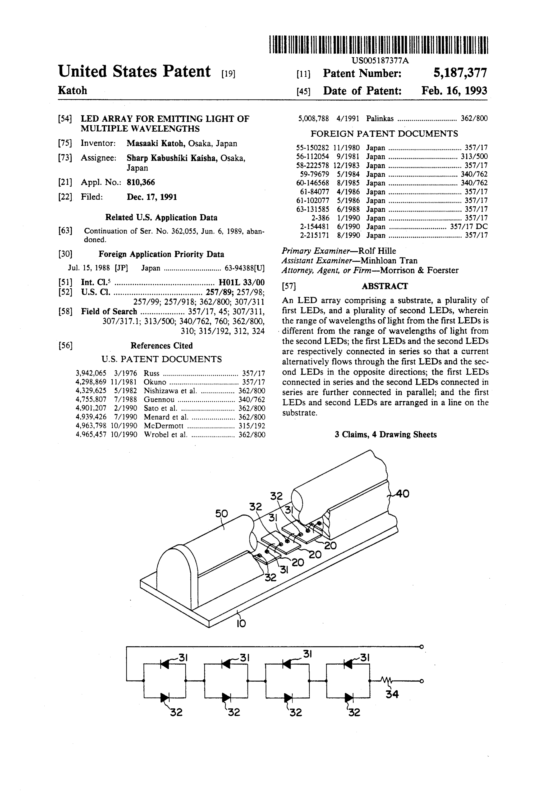
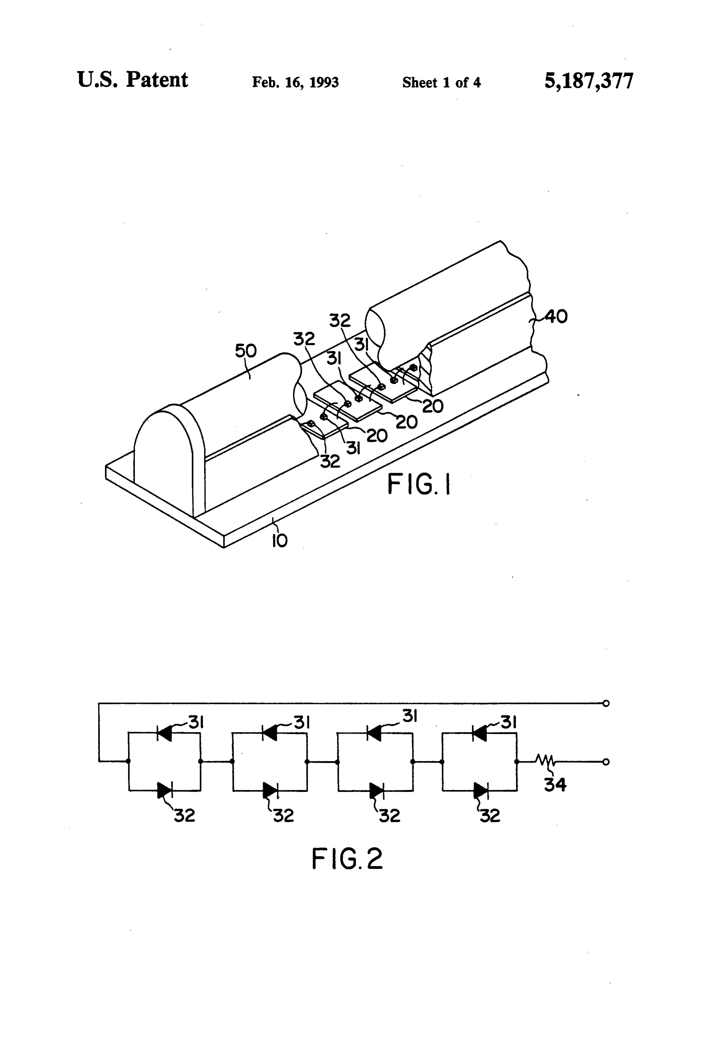
apparatus or the like. FIG. 1 is a perspective view showing the main por Thus, when a conventional LED array is applied to a 45 tion of an LED array of the invention. light source in an image sensor used in a facsimile appa FIG. 2 is an equivalent circuit of the LED array of ratus or the like, only one type of LED which emits FIG. 1.
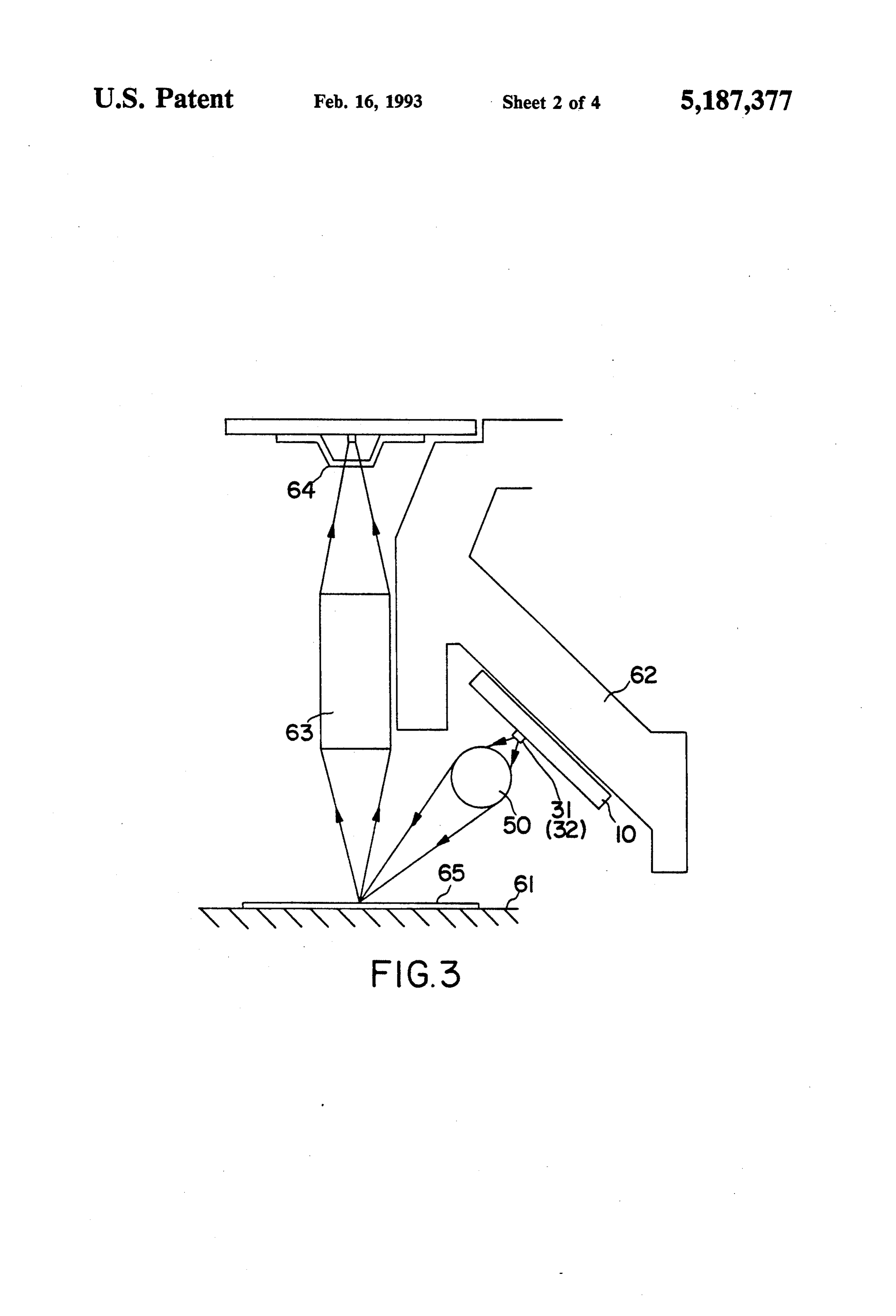
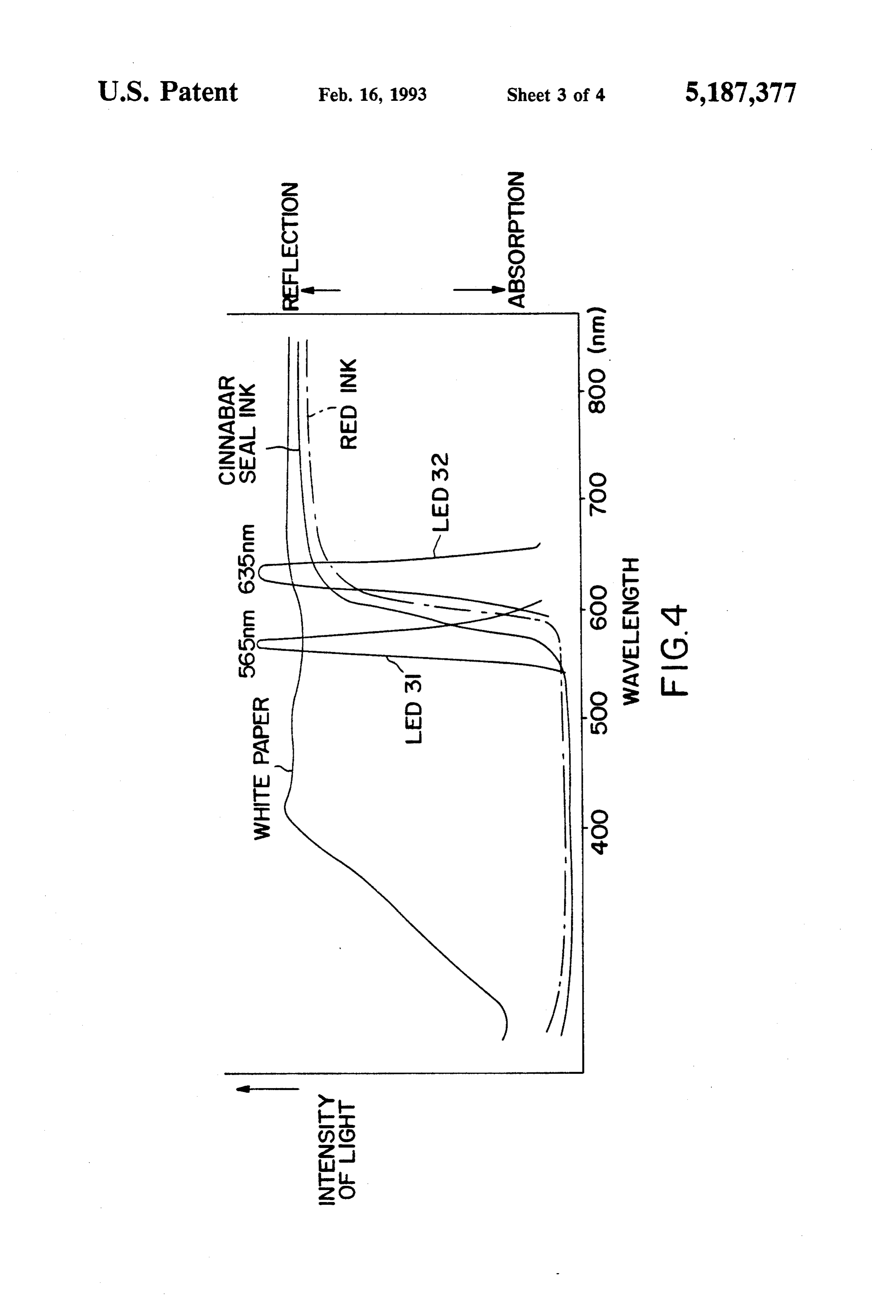
light that is absorbed by the red portions is used. When FIG. 3 diagrammatically shows an image sensor unit the image in the original is constituted by black portions using the LED array of FIG. 1. and red portions, and the original is subjected to the 50 FIG. 4 is a graph showing the relationship between reading process with the image sensor using the LED of the wavelengths and intensity of light from the LEDs this type, both the black portions and the red portions used in the LED array of FIG. 1.
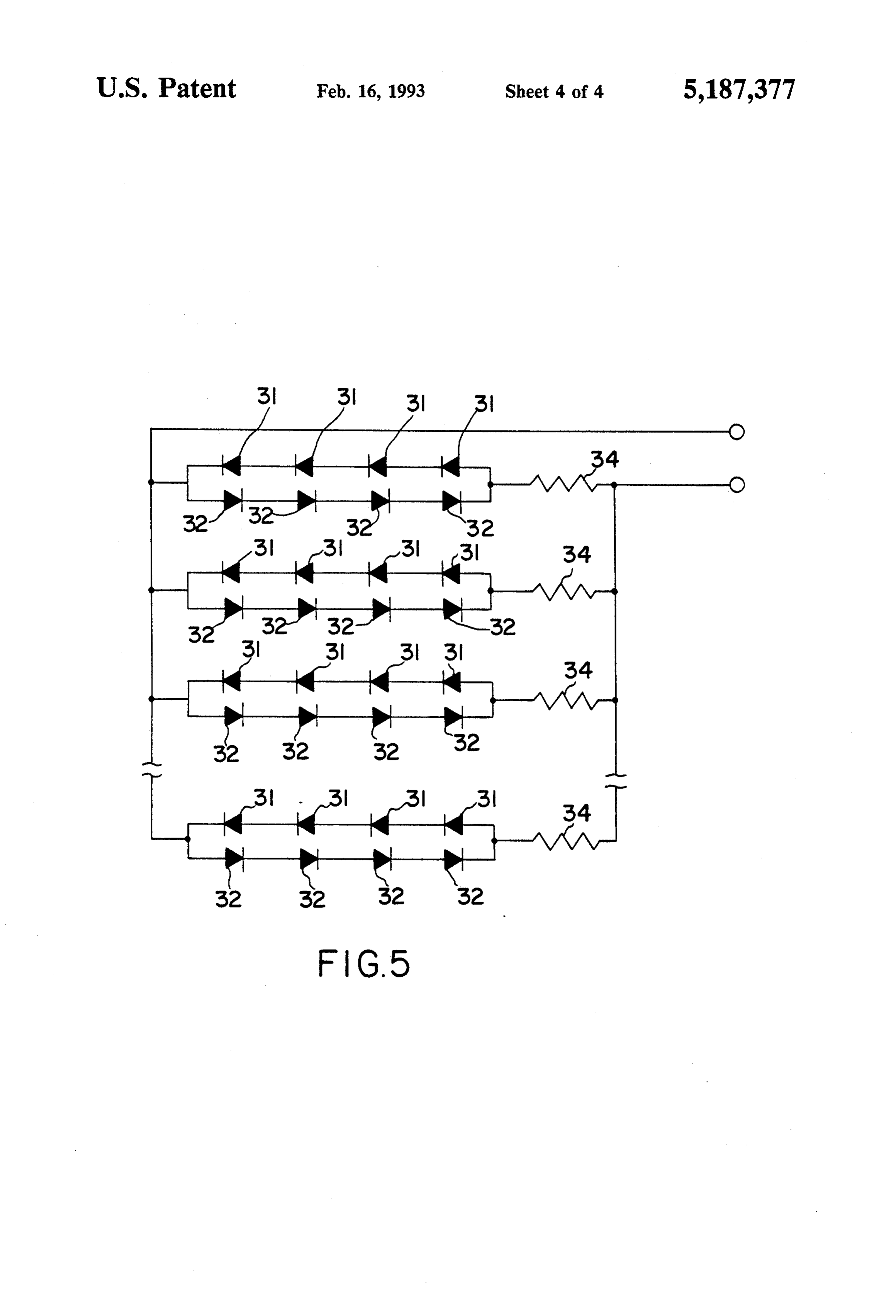
are read by the image sensor, even when it is only neces FIG. 5 is an equivalent circuit of another LED array sary to read the black portions, and the red portions of the invention.
need not be read. In this case, the unnecessary red por 55 DESCRIPTION OF THE PREFERRED tions in the original must be eliminated in advance, EMBODIMENTS which makes the reading process intricate.
When the above-mentioned LEDs for emitting red FIG. 1 shows an LED array of the invention, which light, which is reflected by the red portions because of comprises a substrate 10 in the shape of a rectangular its wavelength, is used in the LED array, the red por 60 parallelepiped, a plurality of metal plates 20 which are tions in the original reflect the red light, so that the arranged in a line on the substrate 10, the first LEDs 31 image sensor is not capable of reading the red portions. which emit light of the wavelength of 565 nm, the sec Thus, when the LED array is provided with the LEDs ond LEDs 32 which emit light of the wavelength of 635 for emitting green or yellowishgreen light and the nm, a pair of reflection plates 40 (only one plate is LEDs for emitting red light, the original is irradiated 65 shown in the figure), and a rod lens 50. The metal plates with red light, if desired, as well as green or yellowish 20 are regularly spaced in the long direction of the green light, so that application of the facsimile appara substrate 10, and on the top of each of the metal plates tus or the like in which the LED array is used is en 20 are a pair of first LED 31 and second LEDs 32 dis
Page 7
posed along the length of the substrate 10, so that all the 635 nm, so that the red light is reflected by cinnabar seal LEDs on the metal plates 20 are arranged in a line. The ink and red ink. When it is necessary to reproduce the top face of each of the first and second LEDs function red portions of the original, the current is allowed to as a light-emitting face, and the top face of the first flow only in one direction through the LEDs 31 for LED is connected to one adjacent metal plate 20 while 5 emitting green light, so that the original 65 is irradiated the top face of the second LED is connected to the next with green light, which is absorbed by the red portions adjacent metal plate 20. in the original, and the image sensor 64 can identify the The pair of reflection plates 40 are disposed on the red portions in the original, the surface of which is substrate 10, in such a manner that the LEDs 31 and 32 colored in white, with certainty.
arranged in a line are interposed between the pair of O On the other hand, when it is not necessary to repro reflection plates 40. The reflection plates 40 support the duce the red portions of the original, the current is rod lens 50 which extends in the same direction that the allowed to flow in the other direction through the LEDs 31 and 32 are arranged. There is a fixed spacing LEDs 32 for emitting red light, so that the original 65 is between the rod lens 50 and the LEDs 31 and 32 dis irradiated with the red light. In this case, however, the posed on the substrate 10. 15 red light is reflected by the red portions as well as the FIG. 2 is an equivalent circuit of the LED array white of the original 65, and the image sensor 64 cannot described above. In the figure, the LEDs 31 which emit identify the red portions in the original so that the re green light are connected in series via the metal plates produced image without the portions which correspond 20 so that a current flows through the LEDs 31 in one to the red portions in the original is obtained on the direction, while the LEDs 32 which emit red light are 20 basis of results of the detection. connected in series via the metal plates 20 so that the FIG. 5 is an equivalent circuit of another LED array current flows through the LEDs 32 in the opposite of the invention. With the LED array of this type, a direction that the current flows through the LEDs 31. plurality of series circuits of the first LEDs 31 for emit The LED 31 disposed on one metal plate 20 and the ting green light and a plurality of series circuits of the LED 32 disposed on its adjacent metal plate 20 are second LEDs 32 for emitting red light are connected in connected in parallel. Since the LEDs 3 and 32 are 25 parallel, and these parallel circuits and resistances 34 for made of a semiconductor material, the current is al adjusting luminance of light are further connected to lowed to flow through the LED 31 or 32 only in one constitute a plurality of series circuits, which, in turn, direction. Therefore, when voltage is applied to the are connected to each other in parallel. It is also possible LED array of the invention, the current is allowed to to allow the LEDs 31 alone to emit green light or the flow through only one type of LEDs in the LED array, 30 LEDs 32 alone to emit red light by changing the direc so that light is emitted only from the LEDs through tion of current-flow in the LED array. which the current flows. This means that the type of It is understood that various other modifications will LEDs which emit light is determined by the direction be apparent to and can be readily made by those skilled of current-flow, so that light obtained from the LED in the art without departing from the scope and spirit of array at any one time is either green or red. A resistance 35 this invention. Accordingly, it is not intended that the 34 is used to adjust luminance of light from the LED scope of the claims appended hereto be limited to the array. description as set forth herein, but rather that the claims FIG. 3 shows a cross section of a contact-type linear be construed as encompassing all the features of patent image sensor, which is used in combination with the able novelty that reside in the present invention, includ LED array of the invention, an original stand 61, a base ing all features that would be treated as equivalents 62, and a rod lens 63 for converging light. In the figure, thereof by those skilled in the art to which this inven an original 65 is disposed on the original stand 61, and tion pertains.
the LED array is positioned in such a manner that the What is claimed is:
rod lens 50 faces the original 65 from above at a fixed 45 1. An LED array for use as a light source in a con angle with respect to the original 65, so that the original tact-type linear image sensor, the LED array compris 65 disposed on the original stand 61 is irradiated with ing a substrate, a pair of reflection plates, a rod lens light from the LED array. The substrate 10 of the LED covering the reflection plates, the reflection plates and array is attached to the base 62 made of aluminum, and the rod lens being mounted on the substrate, a plurality light beams from the LED 31 or 32 illuminate the origi 50 of electrodes spaced at equal intervals between the pair nal 65 on the original stand 61 via the rod lens 50. The of reflection plates, and multiple pairs of a first LED reflected light from the original 65 is converged onto and a second LED disposed on the respective elec the contact-type image sensor 64 by means of the rod trodes in such a manner that the first LED and the lens 63 for converging light, so that the original image second LED are connected in parallel, the first LED is read by the contact-type image sensor 64. Then, the and the second LED having different ranges of wave reproduction is obtained on the basis of results of the 55 length, the LED pairs being connected in series detection carried out by the contact-type image sensor wherein the first LEDs and the second LEDs are ar 64. ranged in opposite directions relative to each other so FIG. 4 shows the relationship between the wave that currents flow through the first LEDs and the sec lengths and intensity of light from the LEDs 31 and 32. ond LEDs in opposite directions whereby either the The figure also shows the ranges of wavelengths in first or the second LEDs emit light depending upon the which light is reflected or absorbed by white paper, direction of current flow.
cinnabar seal ink, and red ink. When the LED 31 of the 2. An LED array according to claim 1, wherein each LED array of the invention emits green light, its inten series of LED pairs includes a single resistance for ad sity reaches the peak at the wavelength of 565 nm, so justing luminance of light.
that the green light is absorbed by cinnabar seal ink and 65 3. An LED array according to claim 1, wherein the red ink, and is not reflected by these red pigments. By first LEDs emit green light and the second LEDs emit contrast, when the LED 32 of the LED array emits red red light.
light, its intensity reaches the peak at the wavelength of sk
Provenance
- Collection
- Cited prior art
- Original PDF
- patentimages.storage.googleapis.com →
- Filed
- 1991-12-17
- Pages
- 7
- Method
- pdftotext (the PDF's own text layer) + pdftoppm 300dpi page scans
- Source
- Google Patents bibliographic record
- Granted
- 1993-02-16
- Inventors
- Masaaki Katoh; Sharp Corp
- Transcribed from
- patentimages.storage.googleapis.com →