patent · US5241462
Lighting equipment accessory and lighting apparatus equipped with the same
31 August 1993
Page 1 — bibliographic record
United States Patent (19) 11 Patent Number: 5,241,462 Sugimoto 45 Date of Patent: Aug. 31, 1993 54) LIGHTING EQUIPMENT ACCESSORY AND 56 References Cited LIGHTING APPARATUS EQUIPPED WITH U.S. PATENT DOCUMENTS
THE SAME
2,523,394 9/1950 Rolph et al. ... ... 362/224 76 Inventor: Jiro Sugimoto, 804 3,140,055 7/1964 Long ................................... 362/223 Rainbow-Mansion, 61, Sueyoshicho 3,377,482 4/1968 Podany ... ... 362/2S5 3-chome, Naka-ku, Yokohama-shi, 4,488,208 12/1984 Miller .................................. 362/223 Kanagawa-ken, Japan 4,992,916 2/1991 Henkes ................................ 362/255 Primary Examiner-Richard R. Cole 21 Appl. No.: 821,655 Attorney, Agent, or Firm-Lowe, Price, LeBlanc & Becker
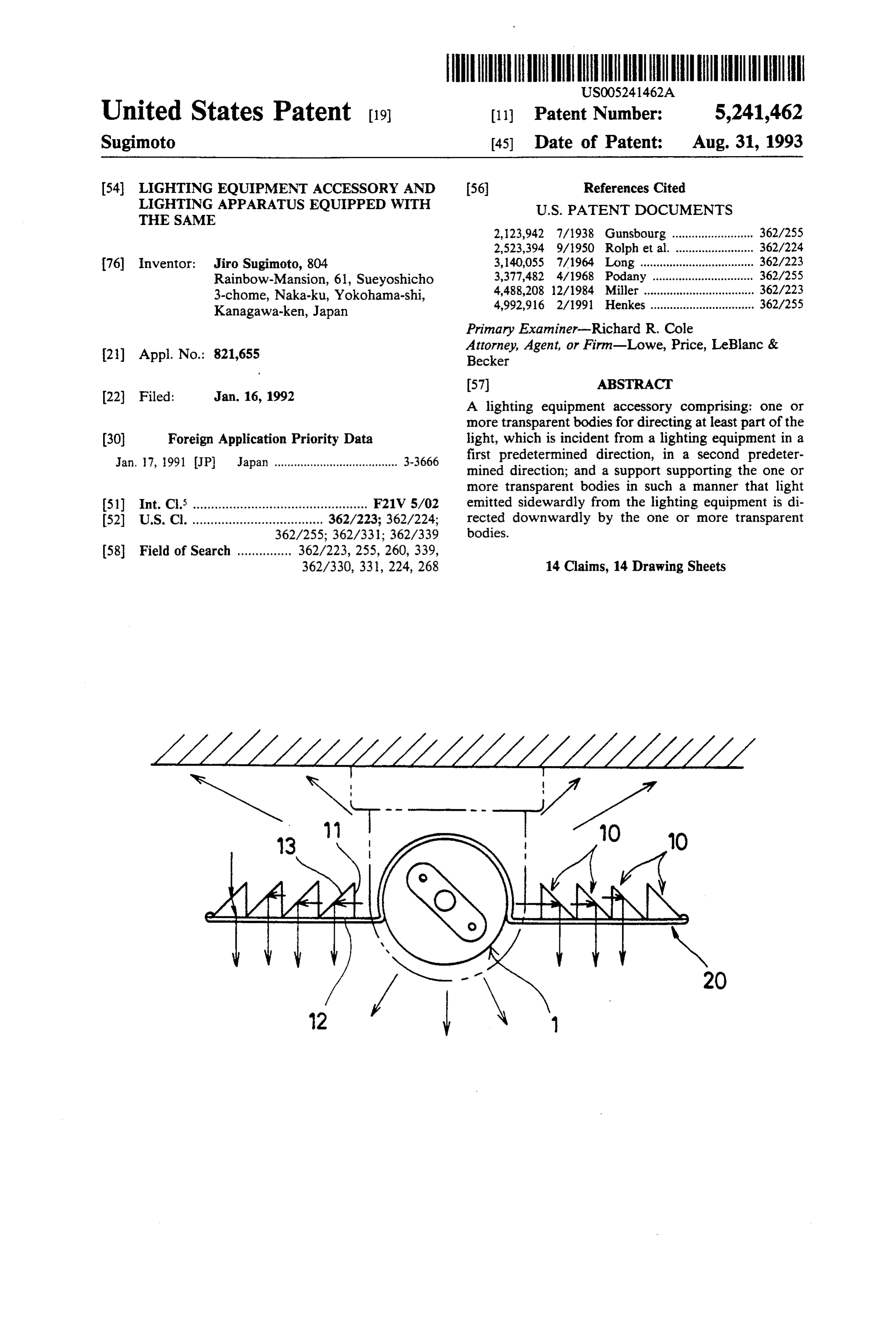
22 Filed: Jan. 16, 1992 A lighting equipment accessory comprising: one or more transparent bodies for directing at least part of the (30) Foreign Application Priority Data light, which is incident from a lighting equipment in a Jan. 17, 1991 JP Japan ..................................... 3-3666 first predetermined direction, in a second predeter mined direction; and a support supporting the one or more transparent bodies in such a manner that light 51) Int. Cl. ................................................ F21V S/02 emitted sidewardly from the lighting equipment is di 52 U.S.C. .................................... 362/223; 362/224; rected downwardly by the one or more transparent
362/330, 331, 224, 268 14 Claims, 14 Drawing Sheets
Page 2
Drawing sheet — no readable text.
Page 3
Drawing sheet — no readable text.
Page 4
Drawing sheet — no readable text.
Page 5
Drawing sheet — no readable text.
Page 6
Drawing sheet — no readable text.
Page 7
Drawing sheet — no readable text.
Page 8
Drawing sheet — no readable text.
Page 9
Drawing sheet — no readable text.
Page 10
Drawing sheet — no readable text.
Page 11
Drawing sheet — no readable text.
Page 12
Drawing sheet — no readable text.
Page 13
Drawing sheet — no readable text.
Page 14
Drawing sheet — no readable text.
Page 15
Drawing sheet — no readable text.
Page 16
to the side of the lighting equipment in parallel to one
LIGHTING EQUIPMENT ACCESSORY AND another in the horizontal and/or vertical directions. LIGHTING APPARATUS EQUIPPED WITH THE Still further, the support may have an attachment SAME adapted to attach the support itself to the lighting equip ent.
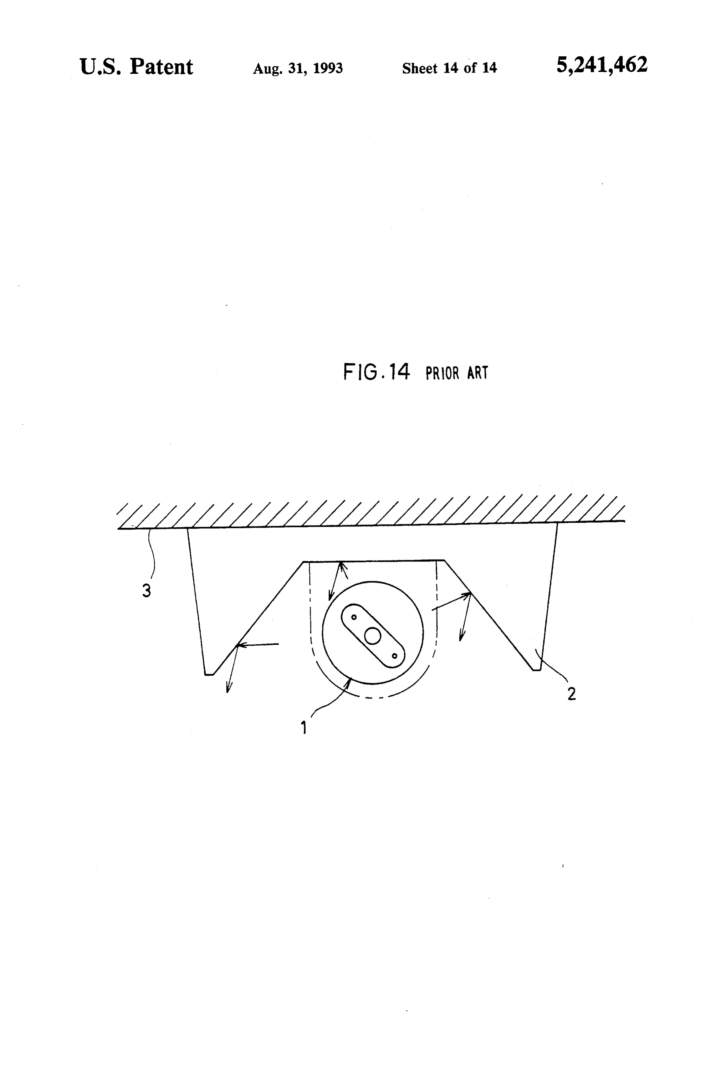
BACKGROUND OF THE INVENTION In operation, light emitted from the upper surface of 1. Field of the Invention the lighting equipment shines directly on the ceiling. This invention relates to a lighting equipment acces Light from the side surface of the lighting equipment is sory to be attached around a lighting equipment. 10 directed downwardly by the transparent body to shine 2. Description of the Related Art the floor. Light from the lower surface of the lighting As shown in FIG. 14 of the accompanying drawings, equipment shines directly on the floor. in many of conventional interior lighting apparatuses, a According to this invention, since light from the side shade 2 covers the top and sides of a fluorescent tube 1 surface of the lighting equipment is directed to the floor so that light emitted upwardly and sidewardly from the 15 without using a shade which can shield light perfectly, fluorescent tube 1 is directed downwards to increase the it is possible to make the whole of the room bright, luminance such as onto a floor in a room.
However, with the conventional lighting apparatus, while the still securing an adequate degree of brightness on floor.
since almost no light can reach the ceiling 3, the ceiling 3 becomes dark so that an occupant might feel anxiety 20 Even if a shade for shielding light is used, it is possible and also the increased contrast in brightness between to make the whole of the room bright such as by direct the floor and the ceiling 3 might strain the eyes of an ing light in the shielded direction using the transparent occupant. This would be a serious problem particularly body.
in a living room where people are intending to make BRIEF DESCRIPTION OF THE DRAWINGS themselves comfortable. 25
SUMMARY OF THE INVENTION
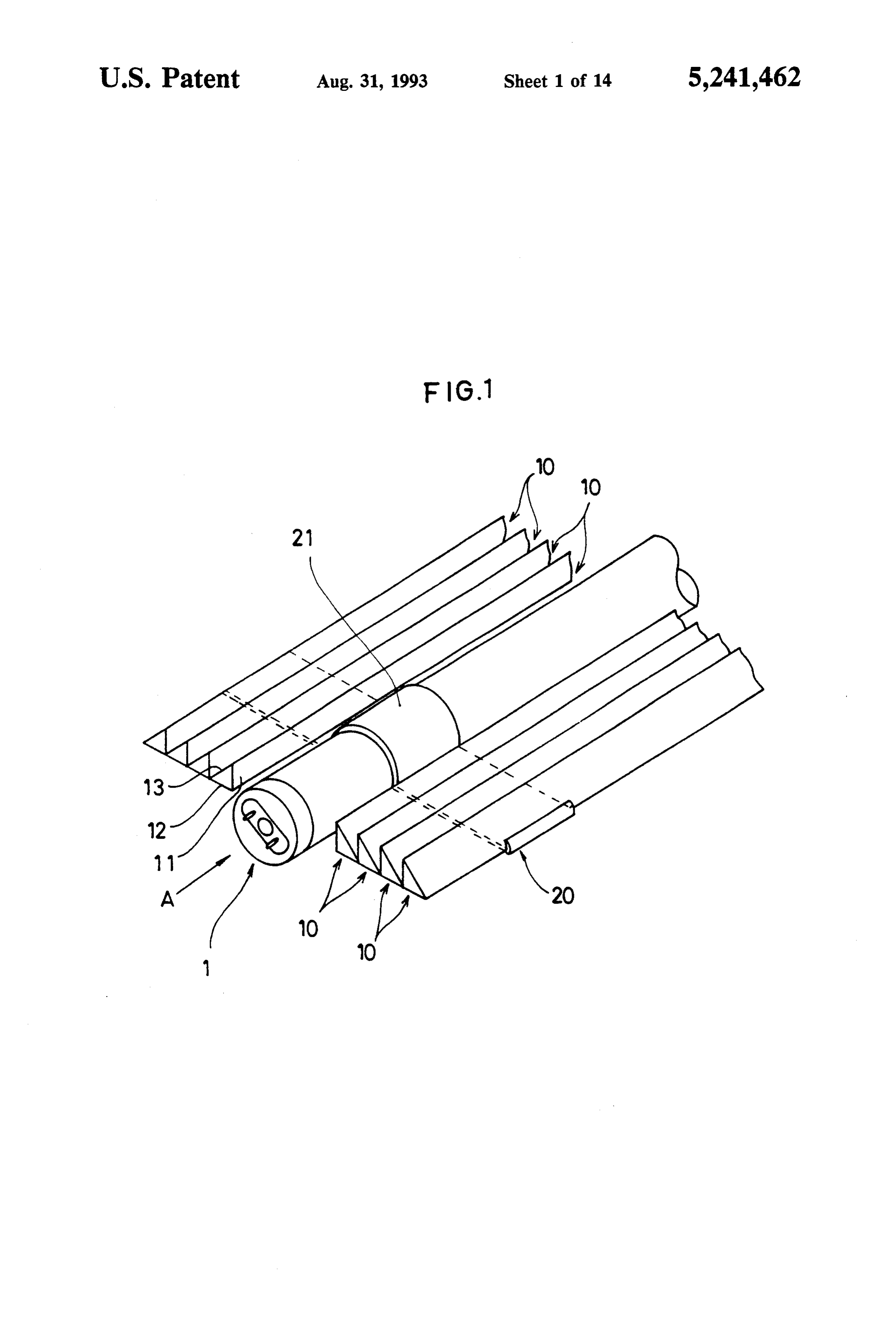
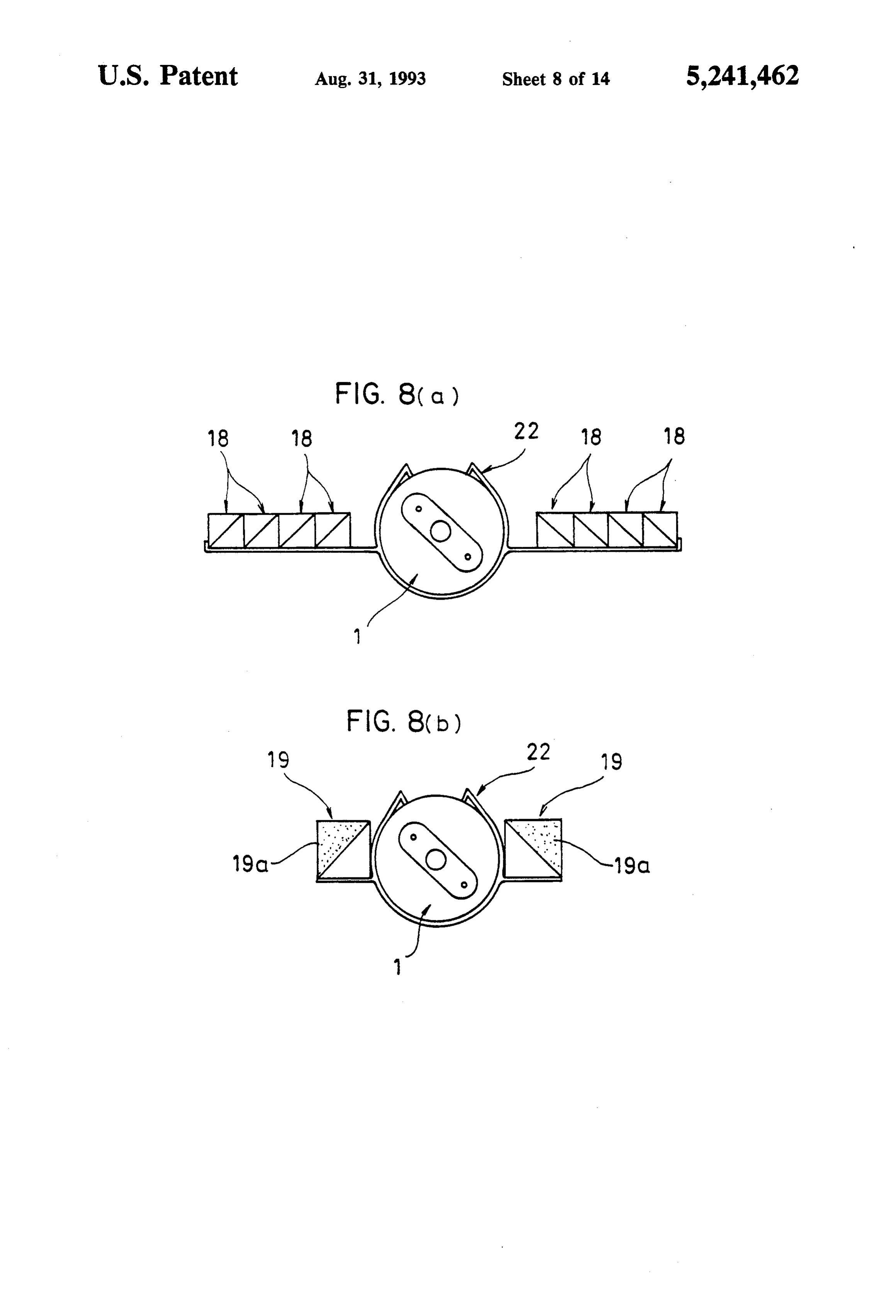
FIG. 1 is a fragmentary perspective view showing a lighting equipment accessory according to a first em
It is therefore an object of this invention to provide a bodiment of this invention;
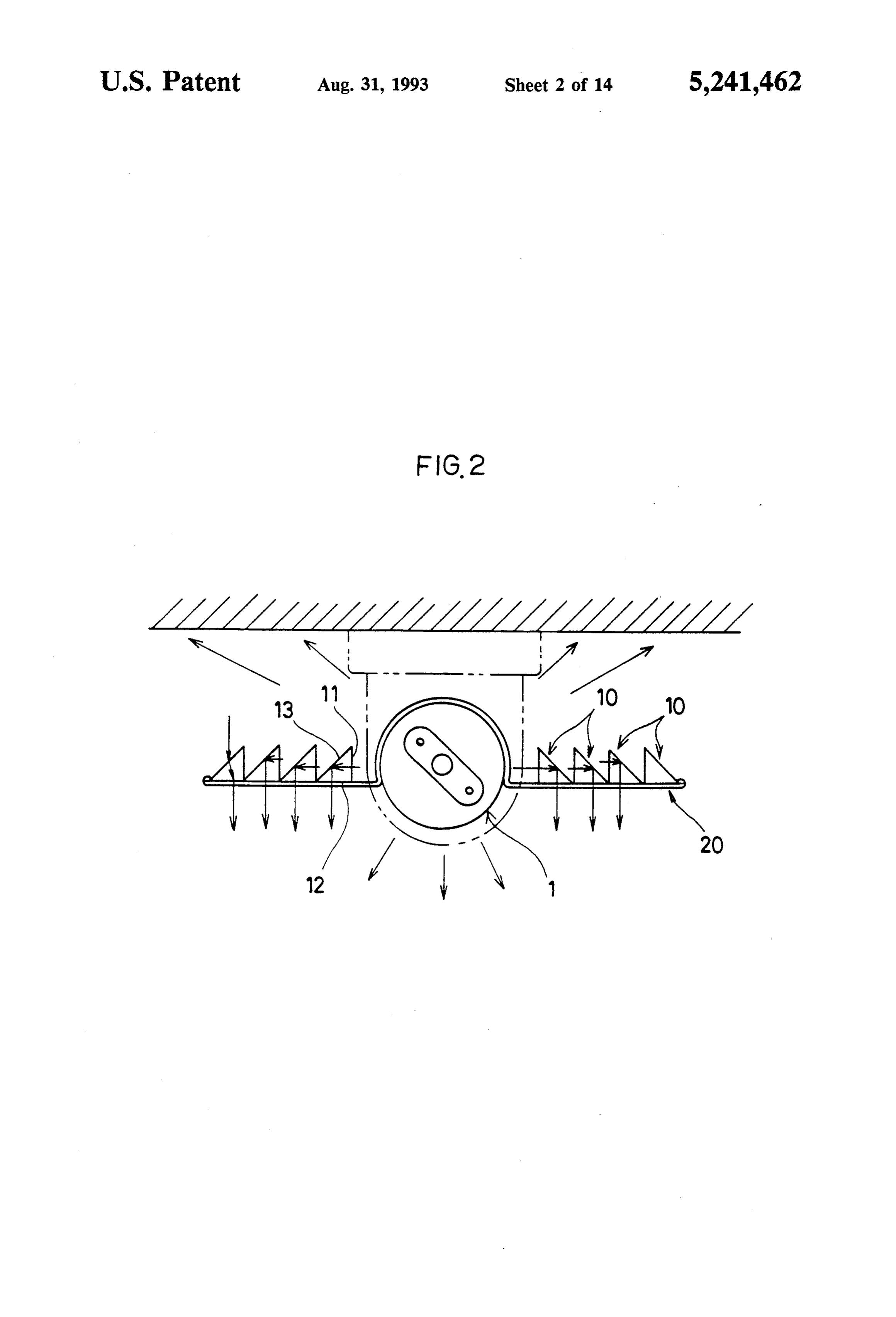
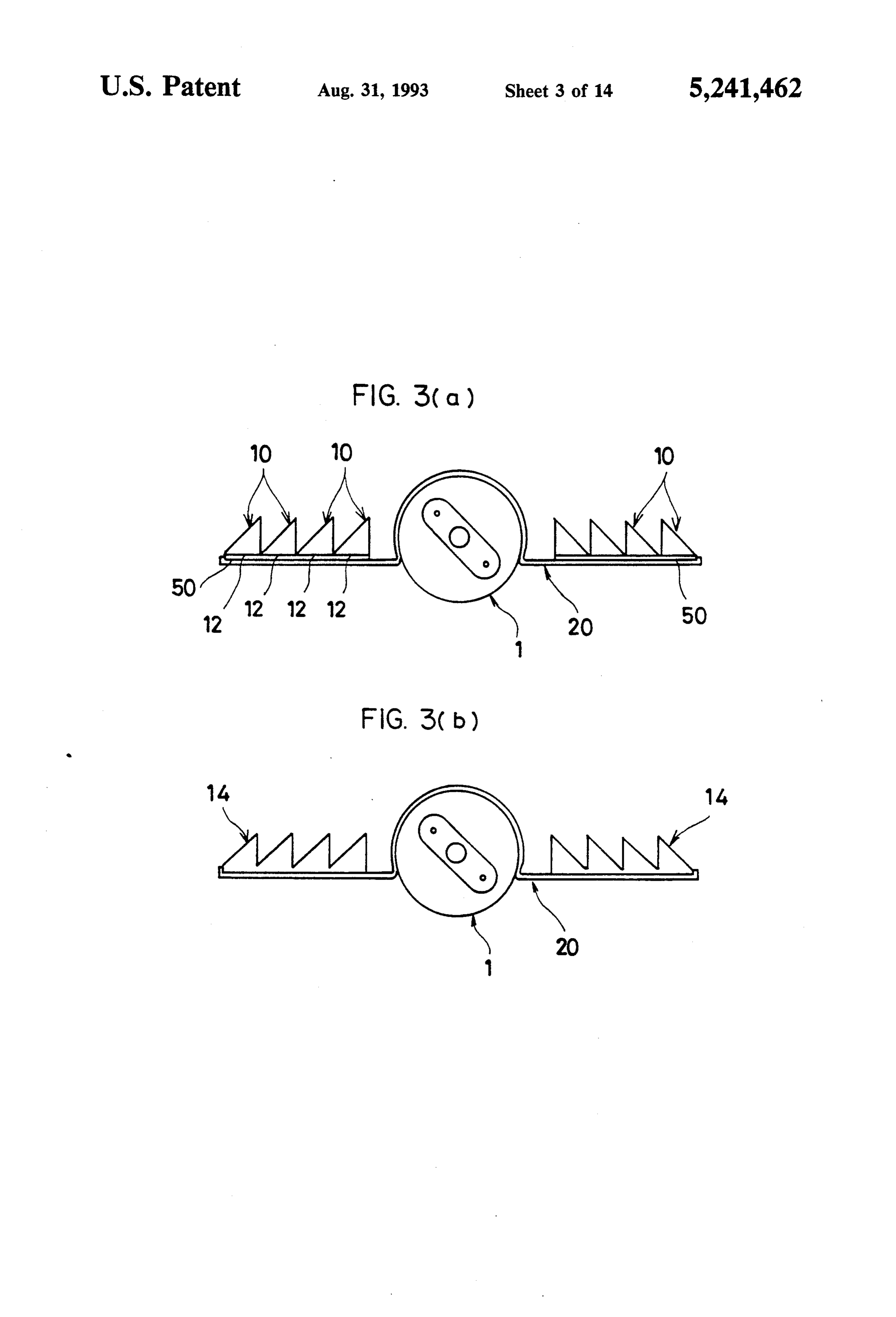
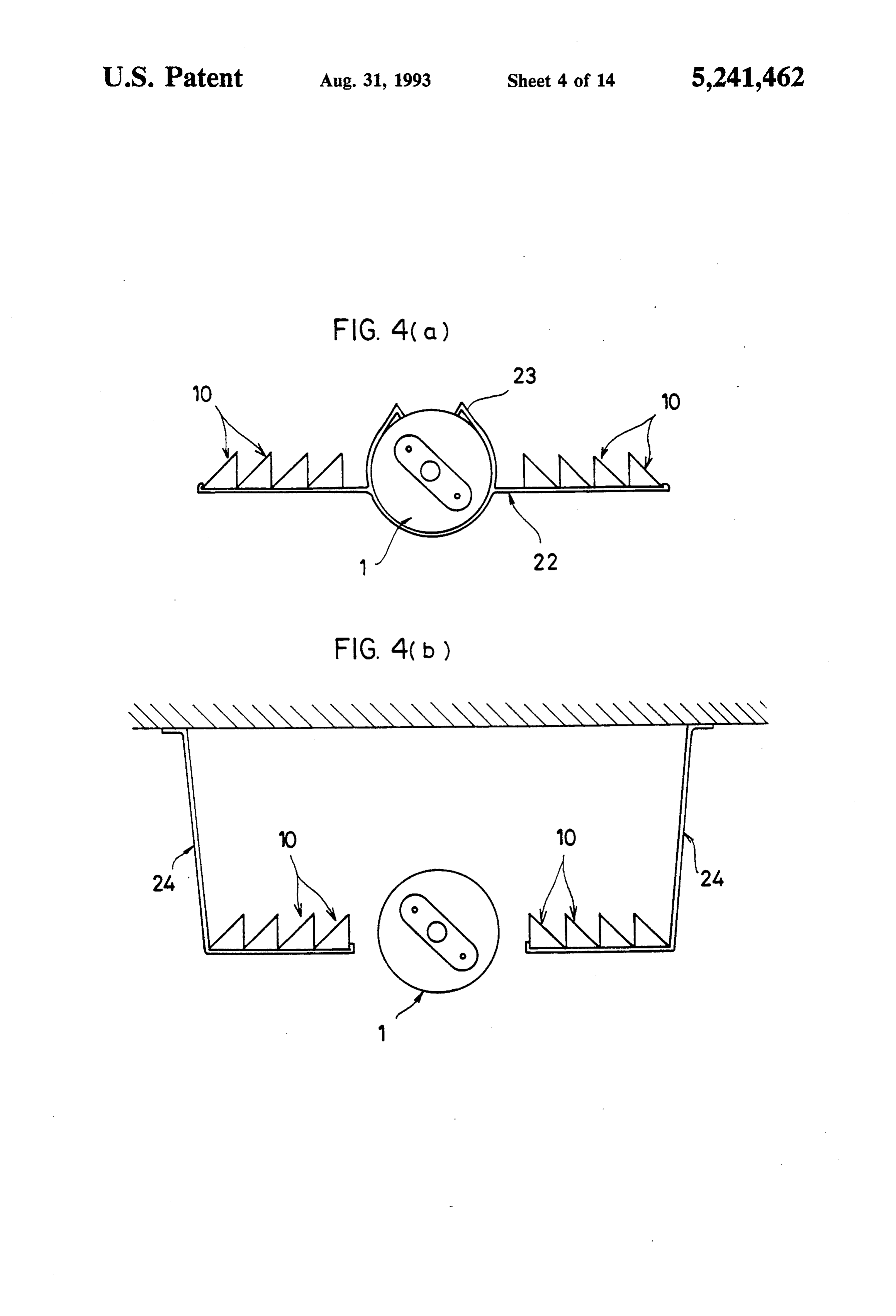
lighting equipment accessory with which directions, FIG. 2 is a view as seen in direction A of FIG. 1; such as the ceiling side, other than the primary direction 30 FIGS. 3(a) and 3(b) are side views showing modified of a light equipment, such as the floor side, can be made lighting equipment accessories according to second and bright, while still securing an adequate degree of bright third embodiments in which transparent bodies are ness in the primary direction of the lighting equipment. connected to one another in alternative forms; According to a first aspect of the invention, there is FIGS. 4(a) and 4(b) are side views showing further provided a lighting equipment accessory comprising: 35 modified lighting equipment accessories according to one or more transparent bodies for directing at least fourth and fifth embodiments in which alternative sup some of the light, which is incident from a lighting ports are used;
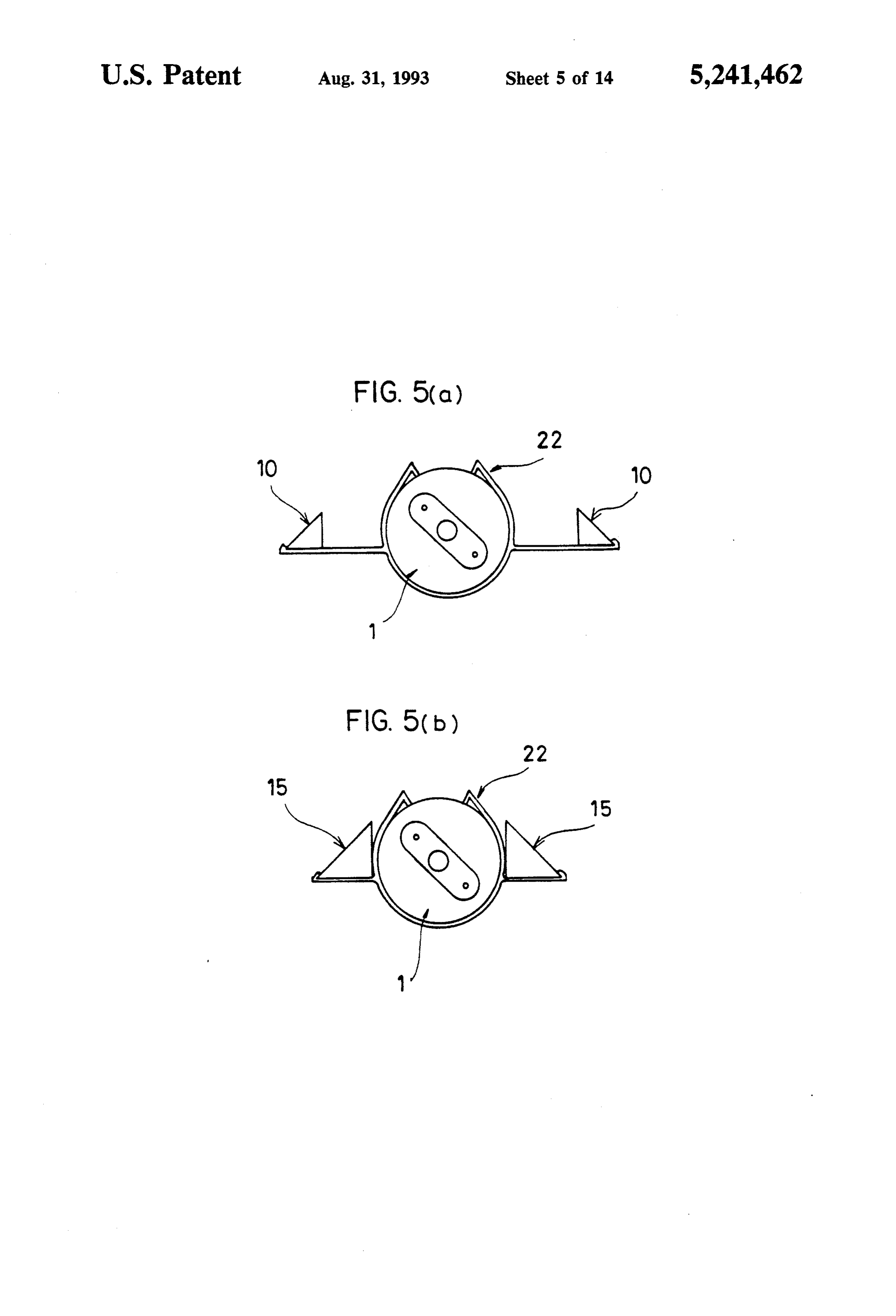
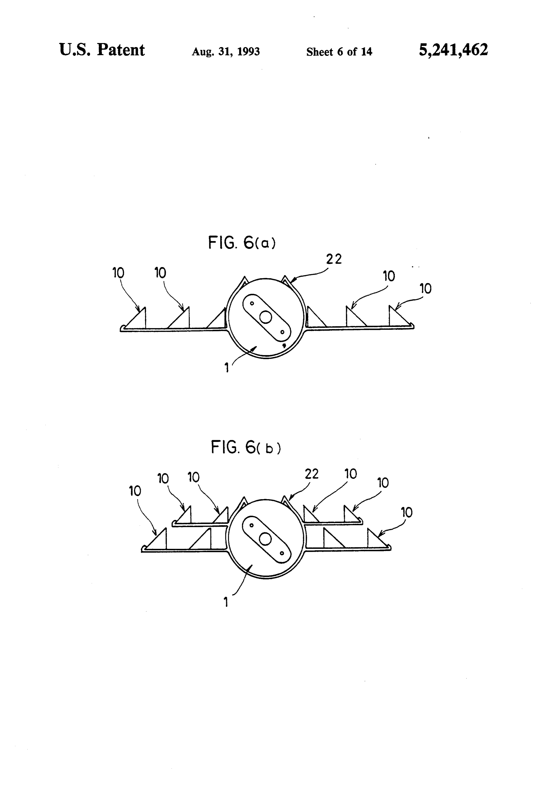
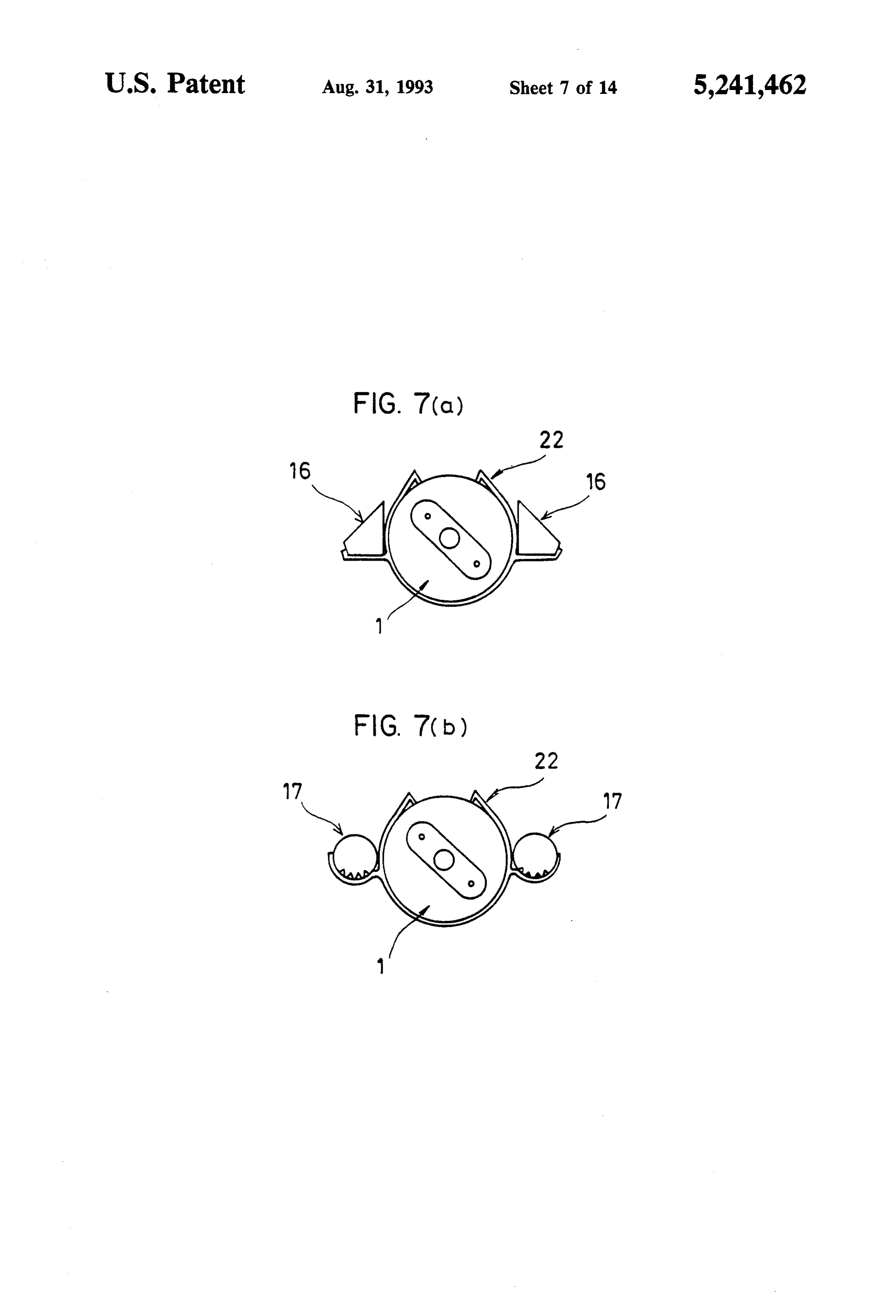
equipment in a first predetermined direction, in a sec FIGS. 5(a) and 5(b) are side views showing still fur ond predetermined direction; and a support supporting ther modified lighting equipment accessories according said one or more transparent bodies in such a manner to sixth and seventh embodiments in which the number that light emitted sidewardly from the lighting equip ment is directed downwardly by said one or more trans of the transparent bodies is different; parent bodies. FIGS. 6(a) and 6(b) are side views showing still fur According to a second aspect of the invention, there ther modified lighting equipment accessories according is provided a lighting equipment accessory comprising: 45 to eighth and ninth embodiments in which the transpar one or more transparent bodies for directing at least ent bodies are arranged in alternative ways; part of light, which is incident from a light equipment in FIGS. 7(a), 7(b), 8(a) and 8(b) are side views showing a first predetermined direction, in a second predeter still further modified lighting equipment accessories mined direction perpendicular to said first predeter according to tenth, eleventh, twelfth and thirteenth mined direction; and a support supporting said one or 50 embodiments in which the transparent bodies have al more transparent bodies in such a manner that light ternative shapes;
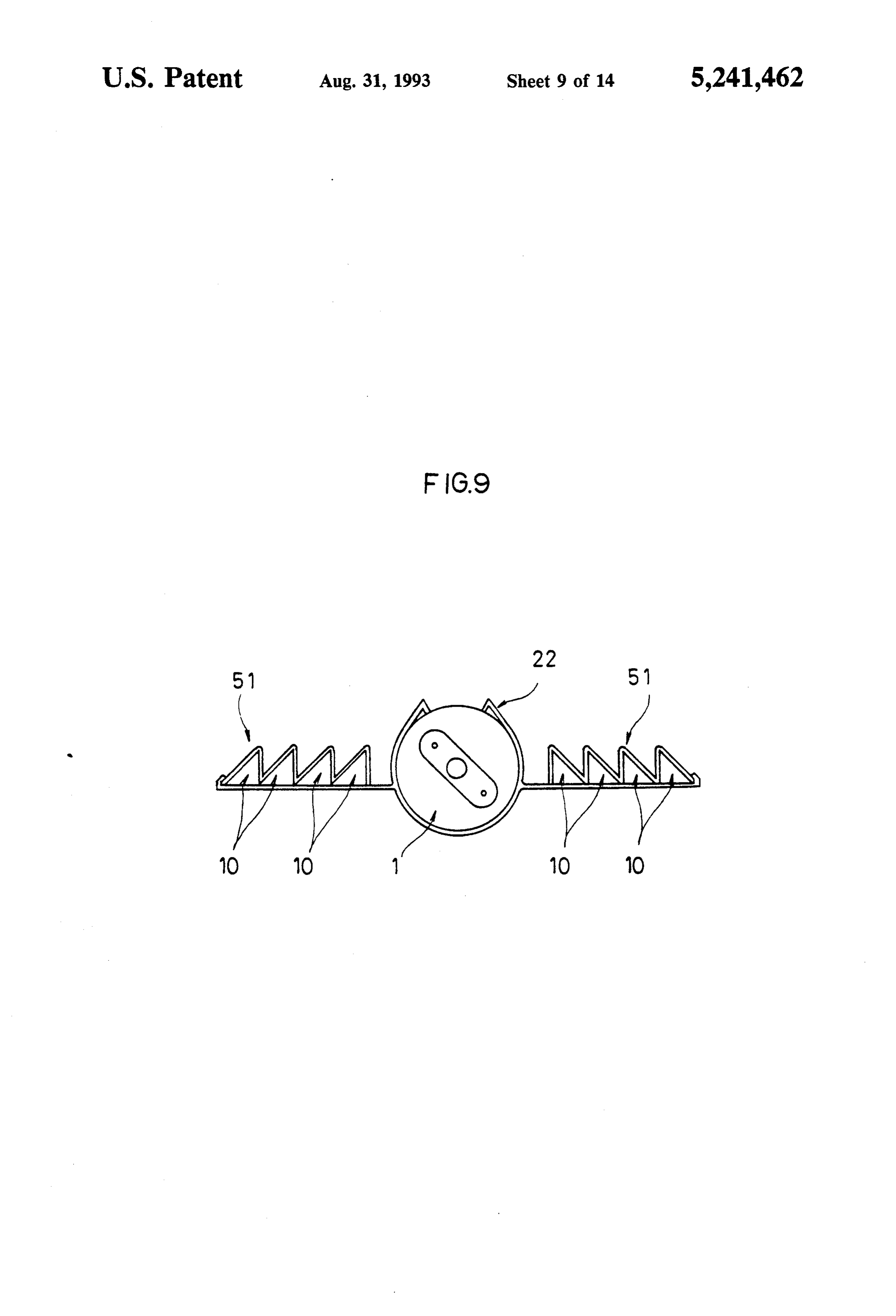
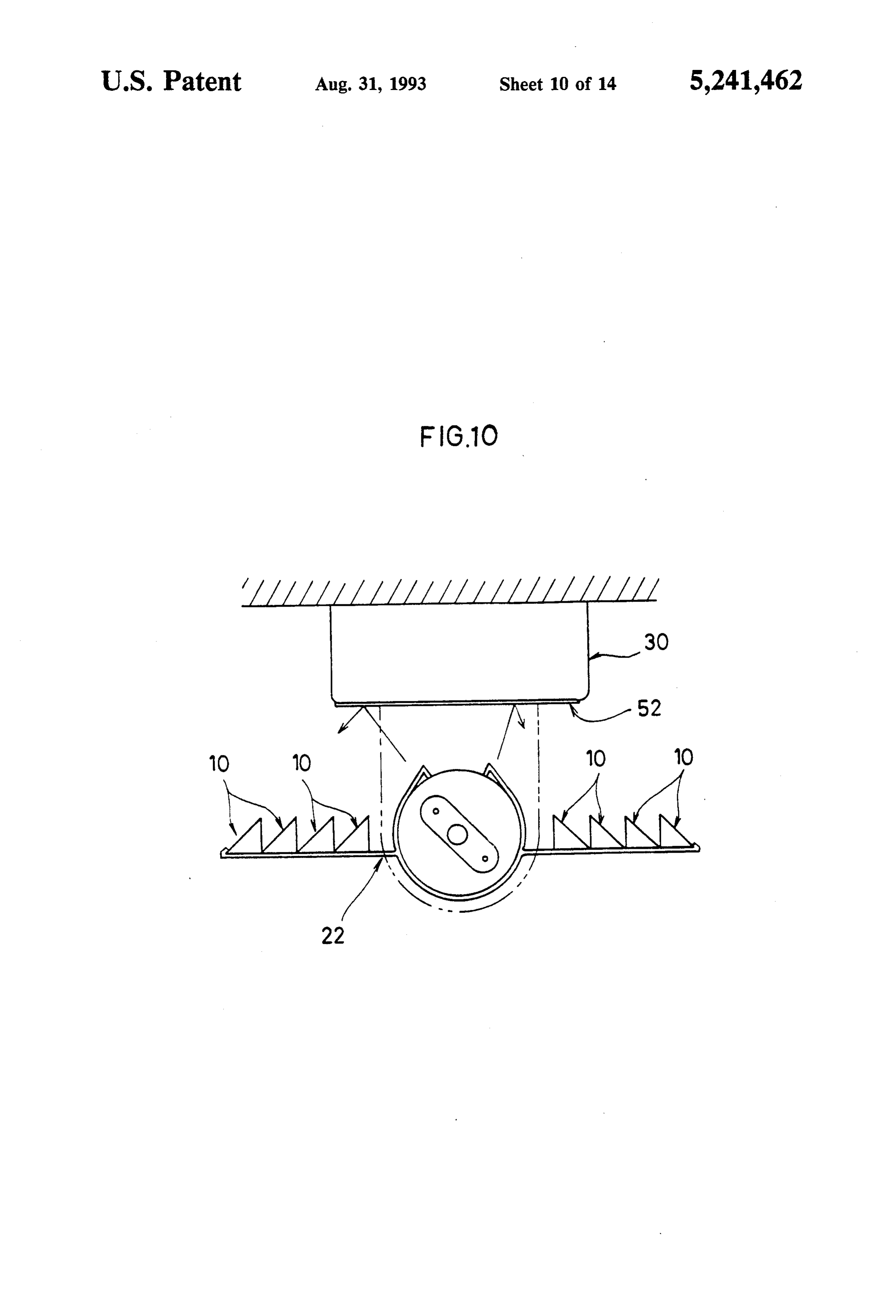
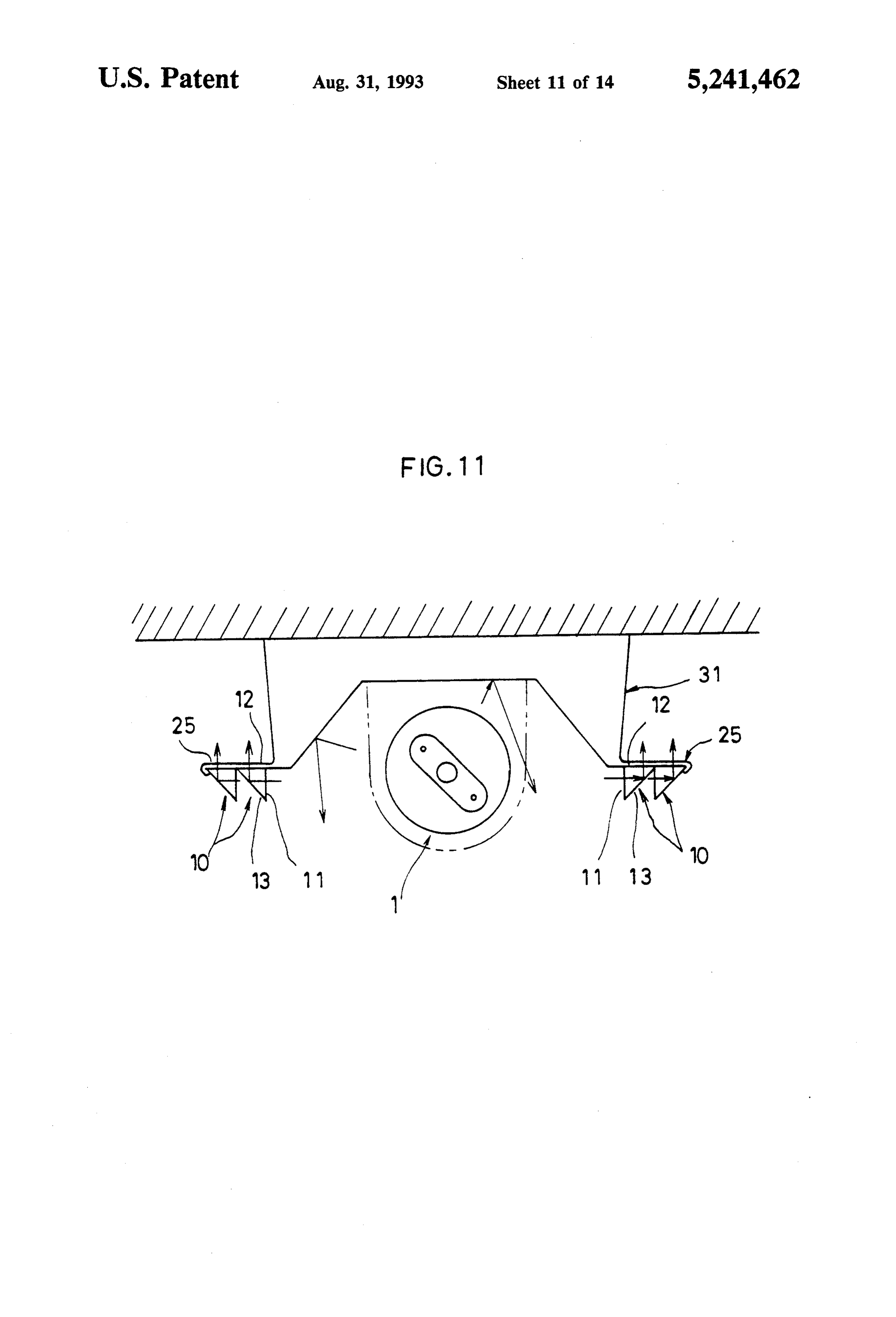
emitted from the lighting equipment substantially per FIG. 9 is a side view showing a still further modified pendicularly to a primary lighting direction of the light lighting equipment accessory according to a fourteenth ing equipment is directed substantially in said primary embodiment in which the transparent bodies are treated light direction by said one or more transparent bodies. 55 by an antielectrostatic process; The transparent body may have a cross sectional FIG. 10 is a side view showing a lighting apparatus shape of a right-angled isosceles triangle, an equilateral according to a fifteenth embodiment; triangle or a pentagon, or it may include two members FIG. 11 is a side view showing a modified lighting which each have a cross sectional shape of a right-an apparatus according to a sixteenth embodiment; gled triangle and are in contact with each other's diago nal surface. Further, the transparent body may contain stillFIG. 12 is a fragmentary perspective view showing a further modified lighting equipment accessory ac a fluorescent material. Preferably the transparent body should be treated at its upper (when the transparent cording to an seventeenth embodiment; FIG. 13 is a fragmentary perspective view showing a body is positioned perpendicularly to the primary light ing direction of the lighting equipment) surfaces by an 65 still further modified lighting equipment accessory ac antielectrostatic process. Furthermore the plurality of cording to a eighteenth embodiment; and transparent bodies may be supported by the support in FIG. 14 is a side view showing a conventional light such a manner that the transparent bodies are positioned ing apparatus.
Page 17
in such a manner that the other surface 12 of the trans
OETAILED DESCRIPTION OF THE
PREFERRED EMBODIMENTS parent body 10 faces in the obliquely downward direc tion.
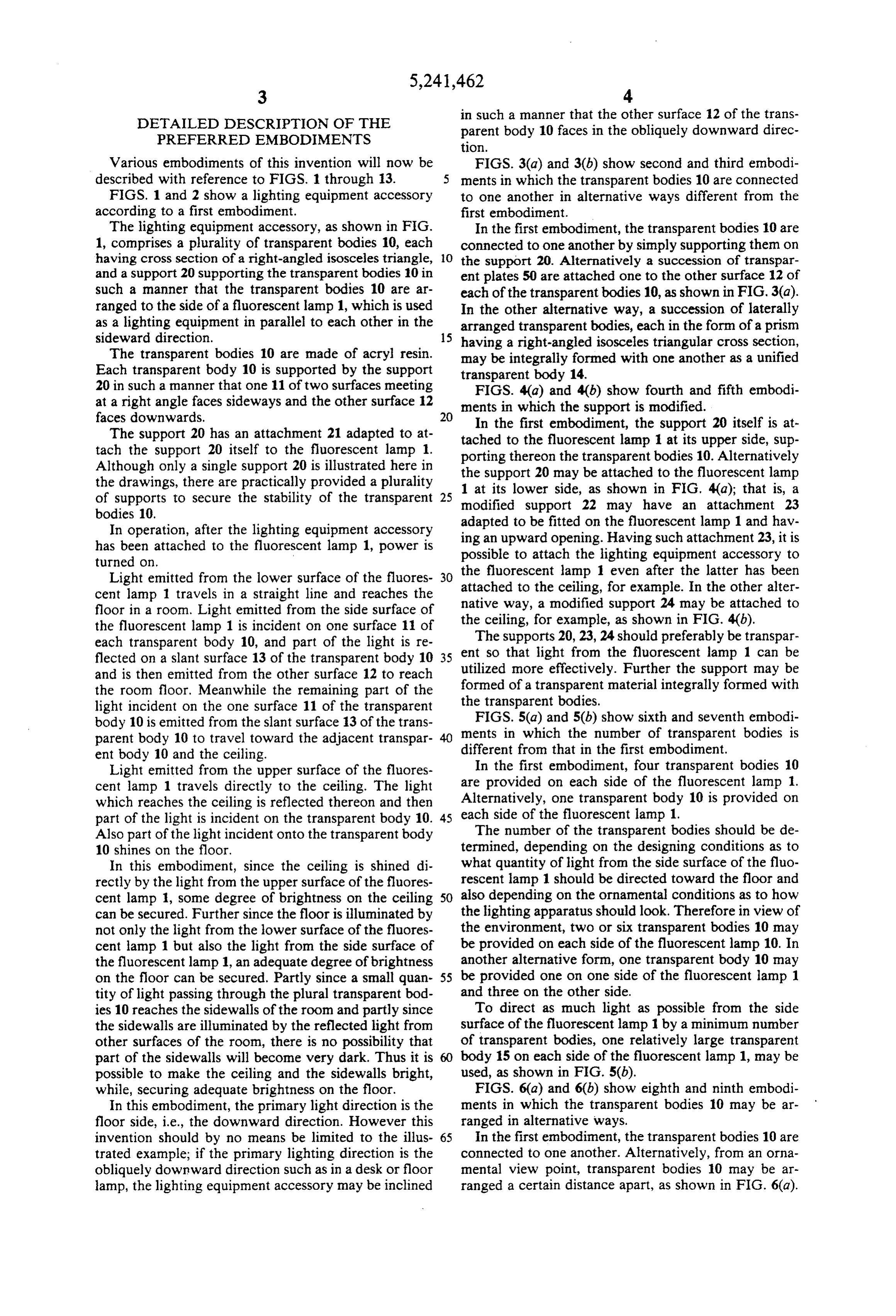
Various embodiments of this invention will now be FIGS. 3(a) and 3(b) show second and third embodi described with reference to FIGS. 1 through 13. ments in which the transparent bodies 10 are connected FIGS. 1 and 2 show a lighting equipment accessory to one another in alternative ways different from the according to a first embodiment. first embodiment.
The lighting equipment accessory, as shown in FIG. In the first embodiment, the transparent bodies 10 are 1, comprises a plurality of transparent bodies 10, each connected to one another by simply supporting them on having cross section of a right-angled isosceles triangle, O the support 20. Alternatively a succession of transpar and a support 20 supporting the transparent bodies 10 in ent plates 50 are attached one to the other surface 12 of such a manner that the transparent bodies 10 are ar each of the transparent bodies 10, as shown in FIG.3(a). ranged to the side of a fluorescent lamp 1, which is used
In the other alternative way, a succession of laterally as a lighting equipment in parallel to each other in thearranged transparent bodies, each in the form of a prism sideward direction. 15 having a right-angled isosceles triangular cross section, The transparent bodies 10 are made of acryl resin.
Each transparent body 10 is supported by the support may be integrally formed with one another as a unified transparent body 14.
20 in such a manner that one 11 of two surfaces meeting FIGS. 4(a) and 4(b) show fourth and fifth embodi at a right angle faces sideways and the other surface 12 ments in which the support is modified.
The support 20 has an attachment 21 adapted to at tached to first
In the embodiment, the support 20 itself is at the fluorescent lamp 1 at its upper side, sup tach the support 20 itself to the fluorescent lamp 1. porting thereon the transparent bodies 10. Alternatively Although only a single support 20 is illustrated here in the support 20 may be attached to the fluorescent lamp the drawings, there are practically provided a plurality 1 at its lower side, as shown in FIG. 4(a); that is, a of supports to secure the stability of the transparent 25 modified support 22 may have an attachment 23 bodies 10.
In operation, after the lighting equipment accessory adapted to be fitted on the fluorescent lamp 1 and hav has been attached to the fluorescent lamp 1, power is ing an upward opening. Having such attachment 23, it is possible to attach the lighting equipment accessory to turned on.
the fluorescent lamp 1 even after the latter has been
Light emitted from the lower surface of the fluores 30 attached cent lamp 1 travels in a straight line and reaches the native way, to the ceiling, for example. In the other alter floor in a room. Light emitted from the side surface of the a modified support 24 may be attached to the fluorescent lamp 1 is incident on one surface 11 of ceiling, for example, as shown in FIG. 4(b). each transparent body 10, and part of the light is re The supports 20, 23, 24 should preferably be transpar flected on a slant surface 13 of the transparent body 10 35 ent so that light from the fluorescent lamp 1 can be utilized more effectively. Further the support may be and is then emitted from the other surface 12 to reach the room floor. Meanwhile the remaining part of the formed of a transparent material integrally formed with light incident on the one surface 11 of the transparent the transparent bodies.
body 10 is emitted from the slant surface 13 of the trans FIGS. 5(a) and 5(b) show sixth and seventh embodi parent body 10 to travel toward the adjacent transpar ments in which the number of transparent bodies is ent body 10 and the ceiling. different from that in the first embodiment. Light emitted from the upper surface of the fluores In the first embodiment, four transparent bodies 10 cent lamp 1 travels directly to the ceiling. The light are provided on each side of the fluorescent lamp 1. which reaches the ceiling is reflected thereon and then Alternatively, one transparent body 10 is provided on part of the light is incident on the transparent body 10. 45 each side of the fluorescent lamp 1. Also part of the light incident onto the transparent body The number of the transparent bodies should be de 10 shines on the floor. termined, depending on the designing conditions as to In this embodiment, since the ceiling is shined di what quantity of light from the side surface of the fluo rectly by the light from the upper surface of the fluores rescent lamp 1 should be directed toward the floor and cent lamp 1, some degree of brightness on the ceiling 50 also depending on the ornamental conditions as to how can be secured. Further since the floor is illuminated by the lighting apparatus should look. Therefore in view of not only the light from the lower surface of the fluores the environment, two or six transparent bodies 10 may cent lamp 1 but also the light from the side surface of be provided on each side of the fluorescent lamp 10. In the fluorescent lamp 1, an adequate degree of brightness another alternative form, one transparent body 10 may on the floor can be secured. Partly since a small quan 55 be provided one on one side of the fluorescent lamp 1 tity of light passing through the plural transparent bod and three on the other side.
ies 10 reaches the sidewalls of the room and partly since To direct as much light as possible from the side the sidewalls are illuminated by the reflected light from surface of the fluorescent lamp 1 by a minimum number other surfaces of the room, there is no possibility that of transparent bodies, one relatively large transparent part of the sidewalls will become very dark. Thus it is body 15 on each side of the fluorescent lamp 1, may be possible to make the ceiling and the sidewalls bright, used, as shown in FIG. 5(b).
while, securing adequate brightness on the floor. FIGS. 6(a) and 6(b) show eighth and ninth embodi In this embodiment, the primary light direction is the ments in which the transparent bodies 10 may be ar floor side, i.e., the downward direction. However this ranged in alternative ways.
invention should by no means be limited to the illus 65 In the first embodiment, the transparent bodies 10 are trated example; if the primary lighting direction is the connected to one another. Alternatively, from an orna obliquely downward direction such as in a desk or floor mental view point, transparent bodies 10 may be ar lamp, the lighting equipment accessory may be inclined ranged a certain distance apart, as shown in FIG. 6(a).
Page 18
The intertransparentbody space may be provided every ing equipment, i.e., the fluorescent lamp 1. In this em two transparent bodies. bodiment, the amount of light directed to the floor is To direct as much light as possible from the side increased.
surface of the fluorescent lamp 1, the transparent bodies Specifically an aluminum foil 52 having a high reflec 10 may be arranged divided into upper and lower tivity is attached to a fluorescent lamp support 30 at its groups on each side of the fluorescent lamp 1, as shown surface facing the fluorescent lamp 1 for reflecting the in FIG. 6(b). light from the upper surface of the fluorescent lamp 1 so Assuming that a plurality of fluorescent lamps 1 are that it shines on the floor.
to be arranged parallel to one another, it would be pref Alternatively a reflector integrally formed with the erable to arrange the transparent bodies 10 between the O support 22 may be located between the fluorescent lamp fluorescent lamps 1. support 30. In another alternative way, a high-reflec The transparent bodies may be different in size and tivity paint may be coated over the fluorescent lamp /or shape. support 30 at its surface facing the fluorescent lamp 1. FIGS. 7(a), 7(b), 8(a) and 8(b) show tenth, eleventh, In still another alternative way, the surface of the fluo twelfth and thirteenth embodiments in which the trans 15 rescent lamp support 30 may be processed so as to be a parent bodies have alternative shapes, mirrored surface, thus securing an increased degree of As shown in FIG. 7(a), transparent bodies 16 may be reflectivity.
quadrangular in cross section. The shape of the trans Assuming that the ceiling is provided with a reflec parent body may be determined particularly from a tive surface, substantially the same results can be ob designing view point as to which direction the light 20 tained even if the other surface 12 of the transparent from the side surface of the fluorescent lamp 1 is to be body 10 is directed upwardly, namely, even if the light directed in. As shown in FIG. 7(a), in the case where ing equipment accessory according to the foregoing the transparent bodies 16 are substantially in contact embodiments is positioned upside down. In this case, with the fluorescent lamp 1, the fluorescent lamp 1 the light from the side surface of the fluorescent lamp 1 cannot be exchanged easily as it is obstructed by the 25 is incident from one surface 11 of the transparent body transparent bodies 10. Consequently it is preferable to 10, is reflected by the slant surface 13 and is then emit form several cutouts at distances along the transparent ted from the other surface 12 to travel upwardly. Then bodies 10 so that the fingers of a workperson can be this light is reflected by the reflective surface on the inserted into the cutouts. ceiling to shine the floor.
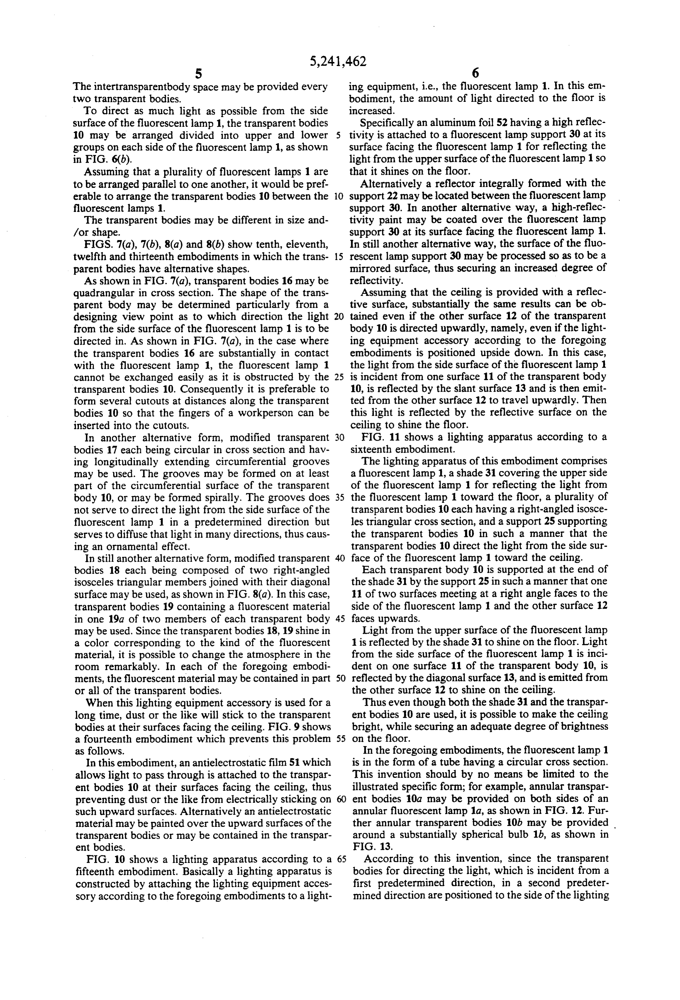
In another alternative form, modified transparent 30 FIG. 11 shows a lighting apparatus according to a bodies 17 each being circular in cross section and hav sixteenth embodiment.
ing longitudinally extending circumferential grooves The lighting apparatus of this embodiment comprises may be used. The grooves may be formed on at least a fluorescent lamp 1, a shade 31 covering the upper side part of the circumferential surface of the transparent of the fluorescent lamp 1 for reflecting the light from body 10, or may be formed spirally. The grooves does 35 the fluorescent lamp 1 toward the floor, a plurality of not serve to direct the light from the side surface of the transparent bodies 10 each having a right-angled isosce fluorescent lamp 1 in a predetermined direction but les triangular cross section, and a support 25 supporting serves to diffuse that light in many directions, thus caus the transparent bodies 10 in such a manner that the ing an ornamental effect. transparent bodies 10 direct the light from the side sur In still another alternative form, modified transparent face of the fluorescent lamp 1 toward the ceiling. bodies 18 each being composed of two right-angled Each transparent body 10 is supported at the end of isosceles triangular members joined with their diagonal the shade 31 by the support 25 in such a manner that one surface may be used, as shown in FIG. 8(a). In this case, 11 of two surfaces meeting at a right angle faces to the transparent bodies 19 containing a fluorescent material side of the fluorescent lamp 1 and the other surface 12 in one 19a of two members of each transparent body 45 faces upwards.
may be used. Since the transparent bodies 18, 19 shine in Light from the upper surface of the fluorescent lamp a color corresponding to the kind of the fluorescent 1 is reflected by the shade 31 to shine on the floor. Light material, it is possible to change the atmosphere in the from the side surface of the fluorescent lamp 1 is inci room remarkably. In each of the foregoing embodi dent on one surface 11 of the transparent body 10, is ments, the fluorescent material may be contained in part 50 reflected by the diagonal surface 13, and is emitted from or all of the transparent bodies. the other surface 12 to shine on the ceiling. When this lighting equipment accessory is used for a Thus even though both the shade 31 and the transpar long time, dust or the like will stick to the transparent ent bodies 10 are used, it is possible to make the ceiling bodies at their surfaces facing the ceiling. FIG. 9 shows bright, while securing an adequate degree of brightness a fourteenth embodiment which prevents this problem 55 on the floor.
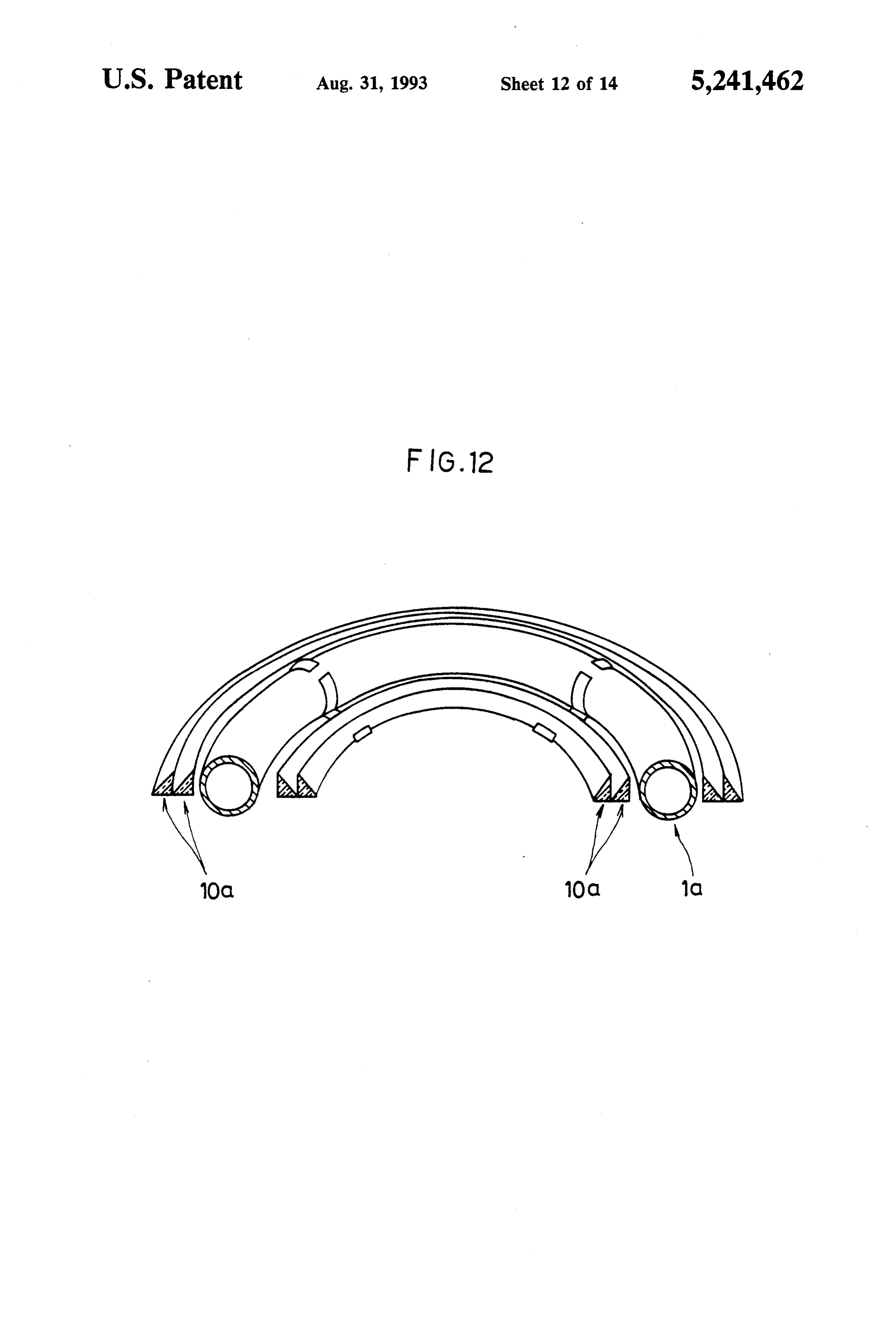
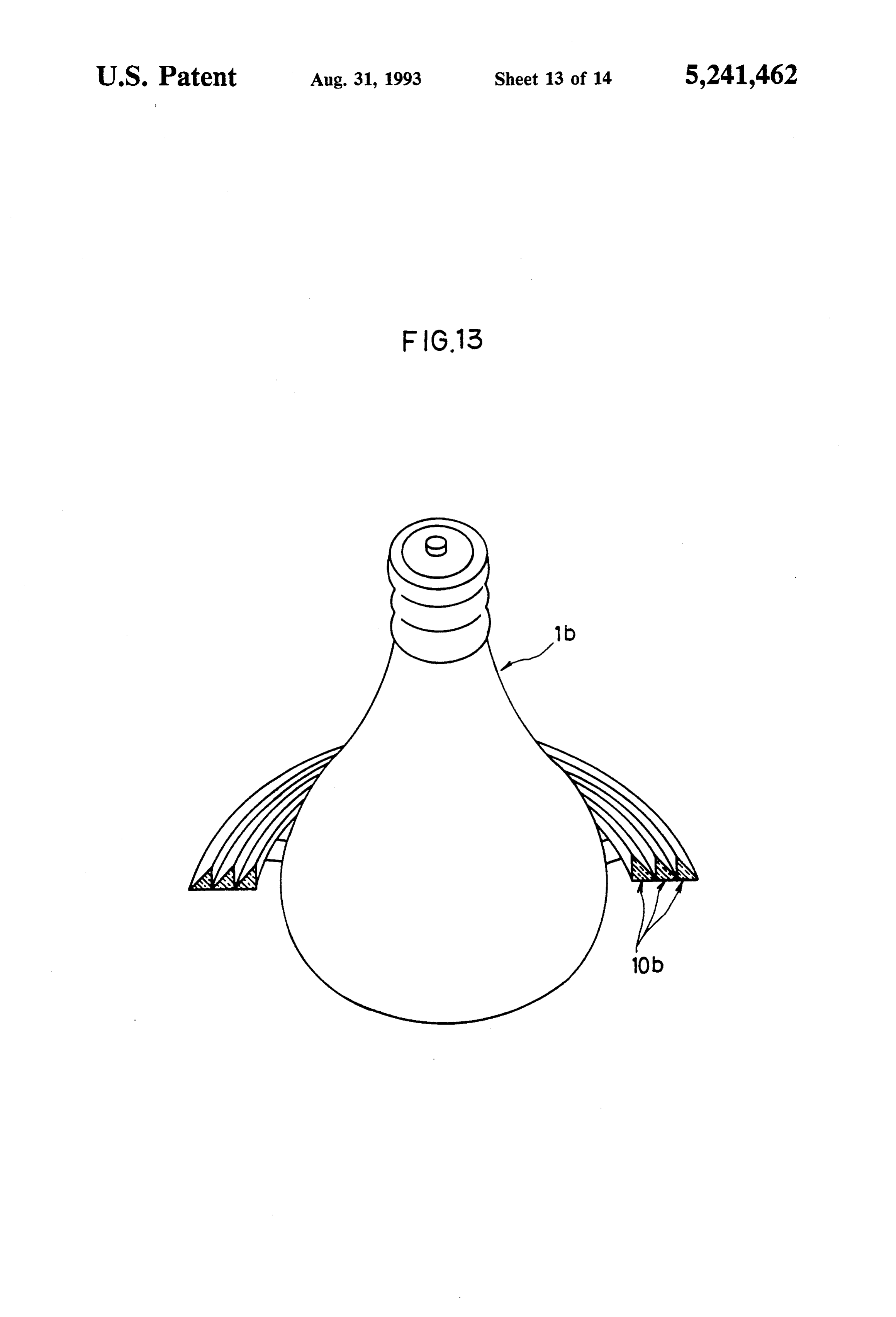
as follows. In the foregoing embodiments, the fluorescent lamp 1 In this embodiment, an antielectrostatic film 51 which is in the form of a tube having a circular cross section. allows light to pass through is attached to the transpar This invention should by no means be limited to the ent bodies 10 at their surfaces facing the ceiling, thus illustrated specific form; for example, annular transpar preventing dust or the like from electrically sticking on ent bodies 10a may be provided on both sides of an such upward surfaces. Alternatively an antielectrostatic annular fluorescent lamp 1a, as shown in FIG. 12. Fur material may be painted over the upward surfaces of the ther annular transparent bodies 10b may be provided transparent bodies or may be contained in the transpar around a substantially spherical bulb 1b, as shown in ent bodies. FIG. 13.
FIG. 10 shows a lighting apparatus according to a 65 According to this invention, since the transparent fifteenth embodiment. Basically a lighting apparatus is bodies for directing the light, which is incident from a constructed by attaching the lighting equipment acces first predetermined direction, in a second predeter sory according to the foregoing embodiments to a light mined direction are positioned to the side of the lighting
Page 19
equipment, directions, such as the ceiling side, other 4. A lighting equipment accessory according to claim than the primary direction of the light equipment, such 3, wherein said support means includes an attachment as the floor side, can be made bright, while securing an SOl adapted to attach said support means to said light adequate degree of brightness in the primary direction. Ce.
5. A lighting equipment accessory according to claim
Therefore it is possible to make all surfaces in the room bright and also to increase the brightness in the primary 3, wherein at least one surface of each of said plurality lighting direction. of transparent bodies is treated with an antielectrostatic What is claimed is: film.
1. A lighting equipment accessory comprising: 6. A lighting equipment accessory according to claim 10 3, wherein said plurality of transparent bodies contain a (a) a plurality of transparent bodies, each arranged to fluorescent material.
direct a first portion of incident light, which has 7. A lighting equipment accessory according to claim been emitted in a first predetermined direction 1, wherein said plurality of transparent bodies each has from a light source, in a second predetermined a triangular cross section.
direction perpendicular to said first predetermined 15 8. A lighting equipment accessory according to claim direction; and 7, wherein at least one surface of each of said plurality (b) support means for supporting said plurality of of transparent bodies is treated with an antielectrostatic transparent bodies and positioning said transparent film.
bodies substantially perpendicularly to a selected 9. A lighting equipment accessory according to claim primary illumination direction of said light source; 20 7, wherein said plurality of transparent bodies contain a wherein said second predetermined direction is gen fluorescent material.
erally parallel to said selected primary illumination 10. A lighting equipment accessory according to direction; and claim 1, wherein said plurality of transparent bodies said plurality of transparent bodies are parallel with contain a fluorescent material.
one another, such that a second portion of incident 25 11. A lighting equipment accessory according to light, different from said first portion of incident claim 1, wherein said support means includes an attach light and incident from said first predetermined ment adapted to attach said support means to a struc direction, passes through one of said plurality of tural surface adjacent said light source. transparent bodies to interact with another of said 30 claim 1,Awherein 12. lighting equipment accessory according to said plurality of transparent bodies are plurality of transparent bodies.
2. A lighting equipment accessory according to claim from said source; and planes outwardly projecting in at least two parallel 1, wherein each of said plurality of transparent bodies said transparent bodies, located in a particular one of includes a pair of members: said parallel planes, are arranged parallel to each wherein each of said pairs of members comprises a 35 other.
perpendicular surface and a diagonal surface ar 13. A lighting equipment accessory according to ranged to have a right-angled triangular cross sec claim 1, wherein said support means includes an attach tion; and ment adapted to attach said support means to said light each of said pairs of members contacts an adjacent SOCC.
pair of members other at a diagonal surface of said 14. A lighting equipment accessory according to adjacent pair of members. claim 1, wherein at least one surface of each of said 3. A lighting equipment accessory according to claim plurality of transparent bodies is treated with an an 1, wherein said plurality of transparent bodies are paral tielectrostatic film. :k k sk lel to one another.
Provenance
- Collection
- Cited prior art
- Original PDF
- patentimages.storage.googleapis.com →
- Filed
- 1992-01-16
- Pages
- 19
- Method
- pdftotext (the PDF's own text layer) + pdftoppm 300dpi page scans
- Source
- Google Patents bibliographic record
- Granted
- 1993-08-31
- Inventors
- Jiro Sugimoto
- Transcribed from
- patentimages.storage.googleapis.com →