patent · US5010869
Air ionization system for internal combustion engines
30 April 1991
Page 1 — bibliographic record
United States Patent (19) 11 Patent Number: 5,010,869 Lee 45 Date of Patent: Apr. 30, 1991
54 AIR IONIZATION SYSTEM FOR INTERNAL
COMBUSTON ENGINES FOREIGN PATENT DOCUMENTS 75) Inventor: Jimmy L. Lee, Rohnert Park, Calif. : ; Elean Pat of mE: 73 Assignee: Zenion Industries, Inc., Rohnert 2476221 8/1981 France. Park, Calif. 0.198366 10/1985 Japan ................................... 123/536 21 Appl. No.: 392,752 Primary Examiner-Andrew M. Dolinar Assistant Examiner-M. Macy 22 Filed: Aug. 11, 1989 Attorney, Agent, or Firm-Larry D. Johnson 51) Int. Cl. ...............is 888 as 8088 v 8 888 888 888 as 888 FO2M 33/00 52 U.S. C. ..................................... 123/539; 123/536 (57) ABSTRACT 58 Field of Search ................ 123/536, 537, 538, 539 This invention relates to a combustion air ionization (56) References Cited method and apparatus for internal combustion engines. In the preferred method, combustion air is moved past
1,873,746 8/1932 English . a series of voltage pulses of a single polarity ranging 3, 10,294 11/1963 Nyman. from a non-zero base voltage to a predetermined peak E. 7. Sight bared voltage is connected in a circuit path to the electrical 3.11.43 A 1973 iny aree charge source. The preferred apparatus practicing this 376,062 9/1973 King method consists essentially of an electrical charge 3,943,407 3/1976 Bolasny. source disposed within a container upstream of the 3,963,408 6/1976 Youngber engine's combustion air intake. The voltage source ap 3,989,017 11/1976 Reece. plies its voltage pulses to the charge source, thereby : As said ionizing the air moving past the charge source. 4,308,844/1982 Persinger. ... 23/539 4,519,357 5/i985 McAllister .......................... 123/537 32 Claims, 4 Drawing Sheets
Page 2
Drawing sheet — no readable text.
Page 3
Drawing sheet — no readable text.
Page 4
Drawing sheet — no readable text.
Page 5
Drawing sheet — no readable text.
Page 6
AR ONZATION SYSTEM FOR INTERNAL
source. The voltage source energizes the charge source
COMBUSTON ENGINES
to ionize the air passing by the charge source.
The preferred apparatus for practicing this method
BACKGROUND OF THE INVENTION consists essentially of an electrical charge source dis 5 posed within a container upstream of the engine's com
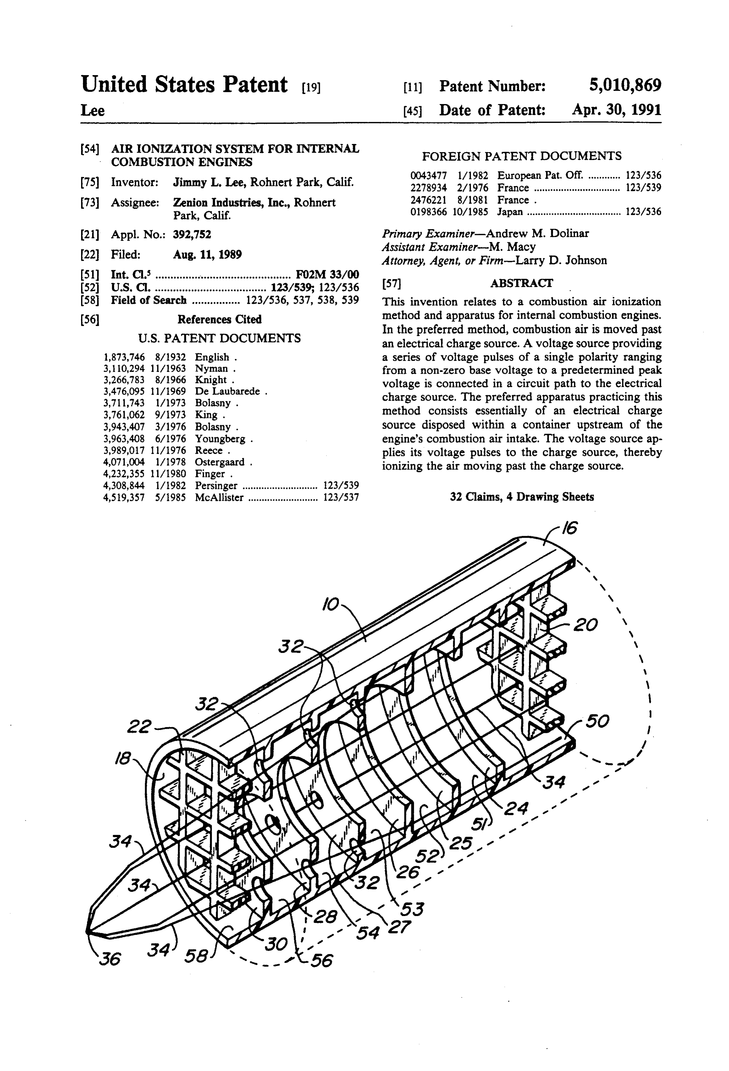
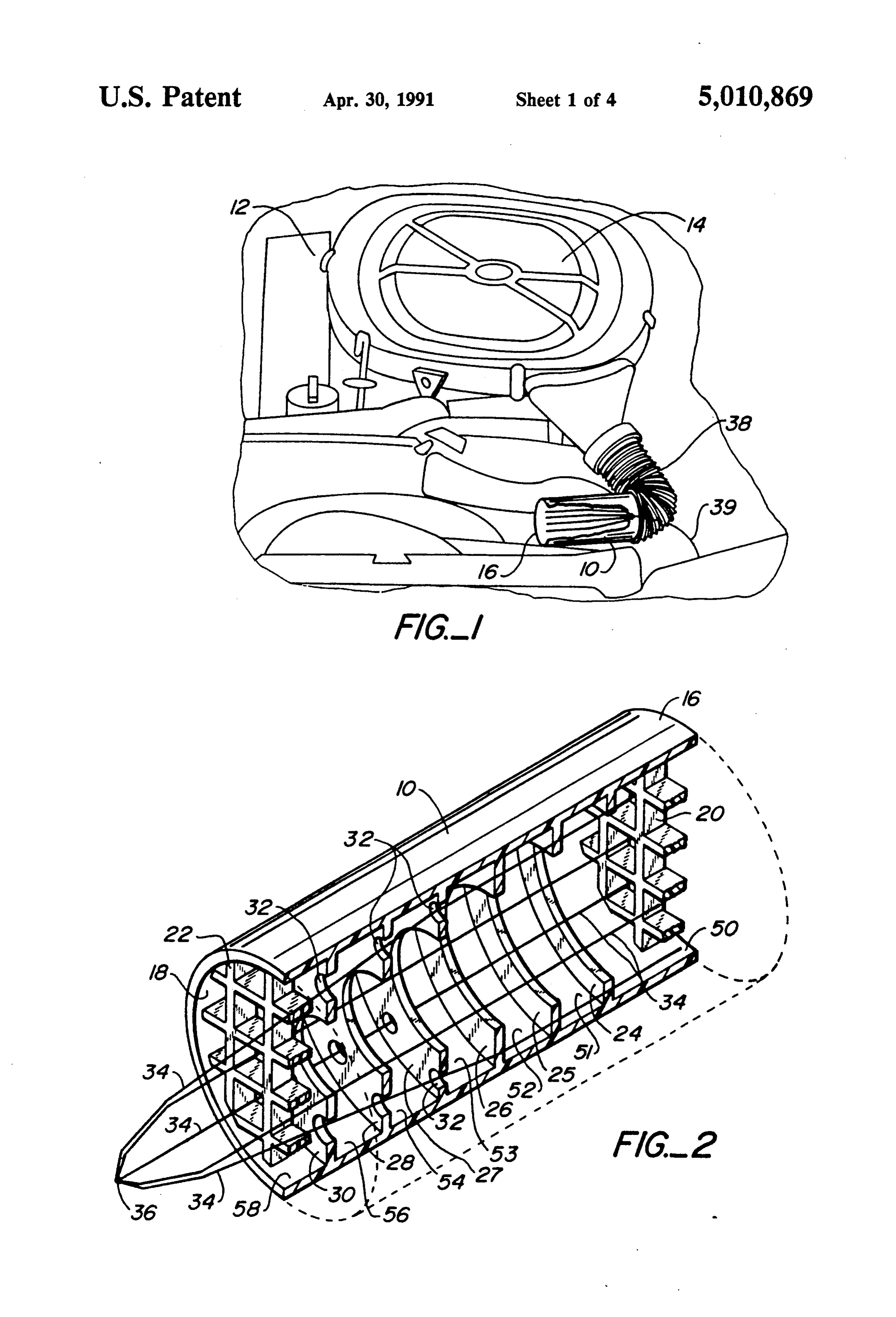
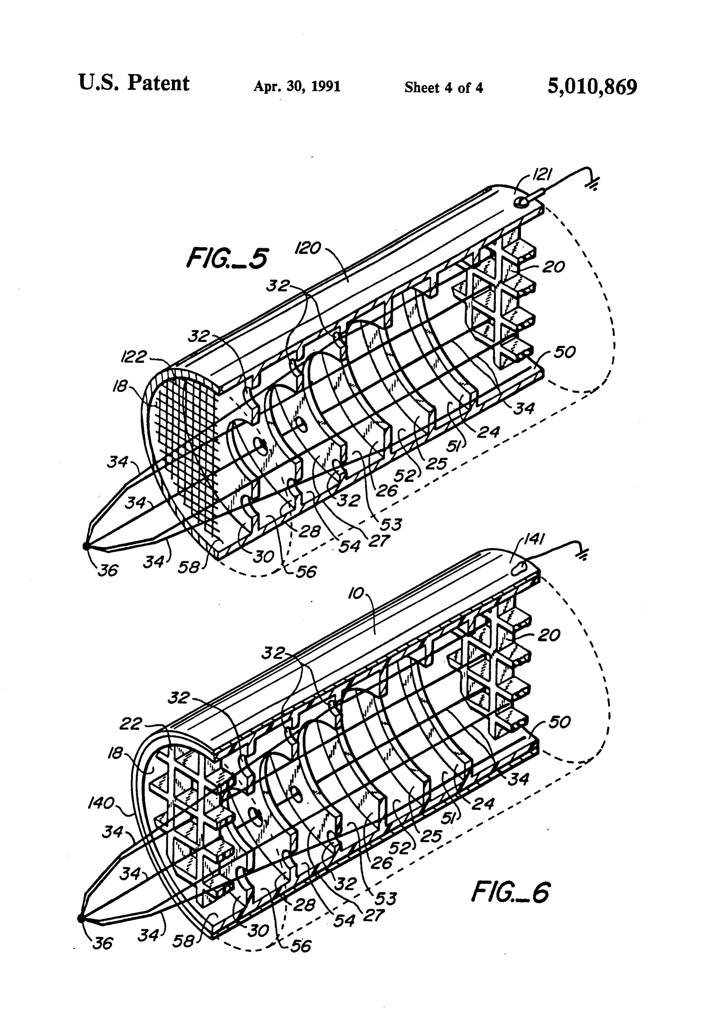
This invention relates generally to air ionization sys bustion air intake. The voltage source applies its voltage tems and in particular to air ionization systems for use pulses to the charge source, thereby ionizing the air with internal combustion engines. moving past the charge source. The prior art is replete with inventions designed to The invention is described more particularly below increase the efficiency of internal combustion engines. O with reference to the drawings. Many of these inventions have focused on techniques designed to improve the mixing of air and fuel. BRIEF DESCRIPTION OF THE DRAWINGS An ionized mixture of air and fuel mixes more thor FIG. 1 is an elevational view of an automobile engine oughly, thereby improving the fuel's combustion. In compartment showing the preferred placement of the addition, most electrostatic techniques produce some apparatus according to this invention for retrofit appli
ozone as a byproduct of the ionization process. Ozone cations.
reacts more readily with hydrocarbons than oxygen FIG. 2 is a sectional view of the preferred embodi does. Furthermore, electrically charged liquid fuel ment of this invention.
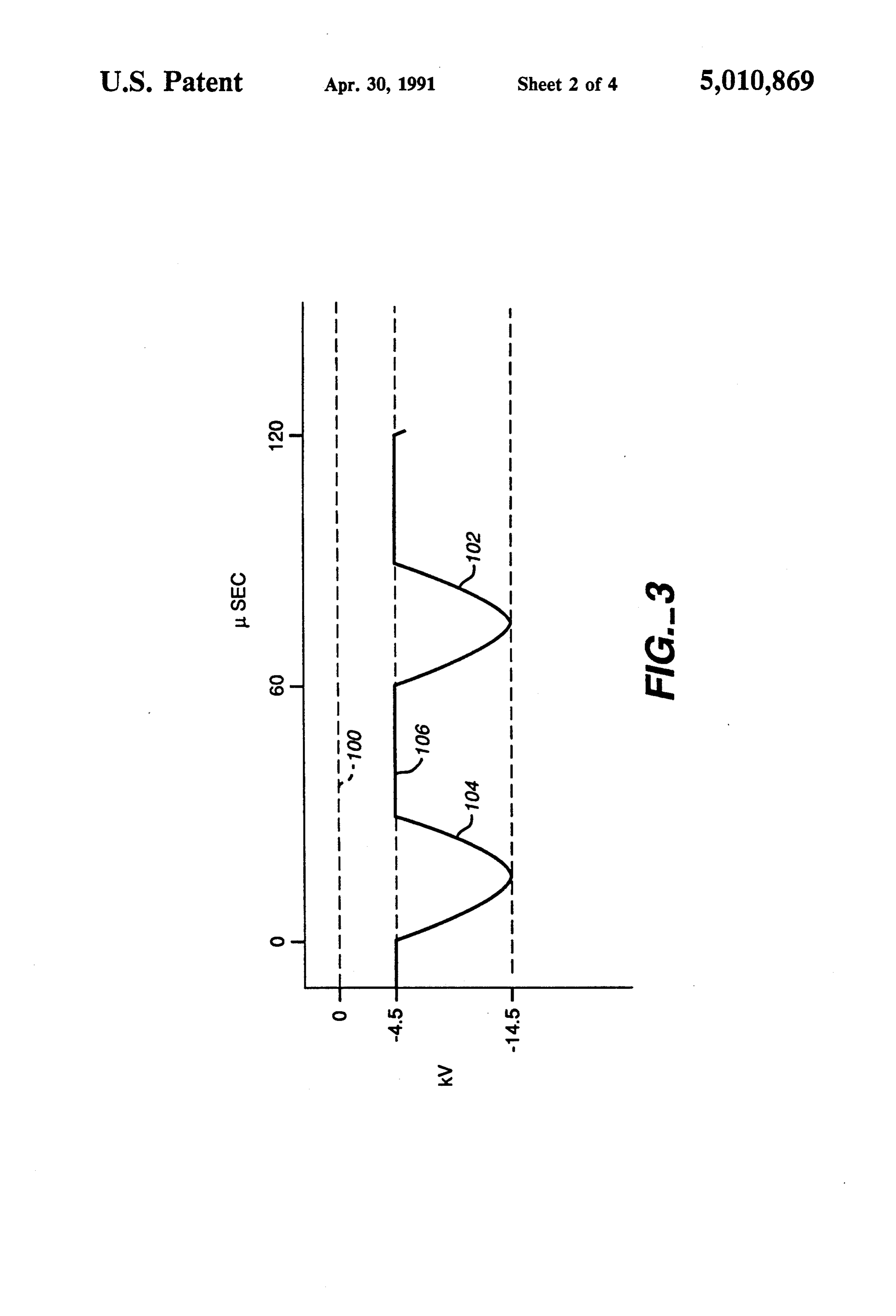
droplets resist coalescing into larger droplets, thereby FIG. 3 is a graph showing the preferred voltage ver permitting the fuel to be mixed more thoroughly with 20 sus time characteristics of the voltage source of this the air. invention.
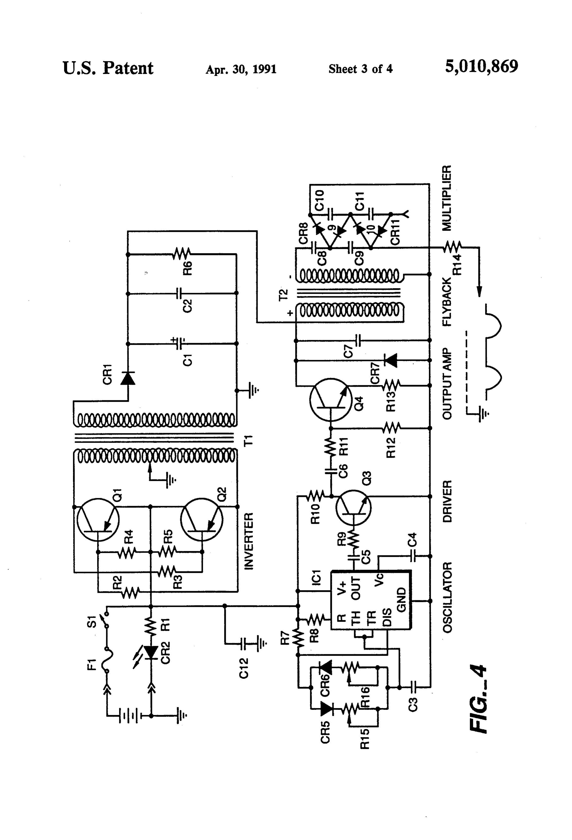
A number of patents disclose methods and appara FIG. 4 is a schematic circuit diagram of the voltage tuses for ionizing combustion air and/or fuel prior to source according to the preferred embodiment of this combustion. Examples are: U.S. Pat. No. 1,873,746; invention.
U.S. Pat. No. 4,071,004; U.S. Pat. No. 3,989,017; U.S. 25 FIG. 5 is a sectional view of an alternative embodi
No. 3,476,095; U.S. Pat. No. 3,266,783; and U.S. Pat. ment of this invention.
No. 3,110,294. The disclosures of these patents are in bodiment6 isofathis
FIG. sectional view of another alternative em invention.
corporated herein by reference.
The prior art has recognized, however, that D.C. 30 DETAILED DESCRIPTION OF THE voltages in excess of 5000 volts tend to produce large PREFERRED EMBODIMENT amounts of ozone. See, e.g., U.S. Pat. No. 3,711,743, the disclosure of which is incorporated herein by reference. The air ionization system according to the preferred Ozone is very reactive and will degrade metal, plastic embodiment of this invention is shown in FIGS. 1 and 2. and rubber components. It is therefore necessary in 35 An ionization tube 10 is inserted in the air intake line of some circumstances to limit the amount of ozone pro an internal combustion engine 12 upstream of an air duced during ionization of air. cleaner 14. Ionization tube 10 has an inlet 16 and an My earlier U.S. Pat. No. 4,789,801 disclosed an elec outlet 18. Inlet 16 is covered by a screen or grid 20 of a trokinetic apparatus for ionizing and moving air while suitable non-conducting material, and outlet 18 is cov minimizing the production of ozone and oxides of nitro ered by a similar screen or grid 22. The purpose of the gen. The disclosure of that patent is incorporated herein screens is to prevent foreign objects from entering the by reference. That patent, however, did not disclose device and to prevent any objects from leaving the any apparatus or method for ionizing combustion air for device and entering the engine's carburetor or intake internal combustion engines. manifold.
SUMMARY OF THE INVENTION 45 Ionization tube 10 is preferably formed from an acrylic polycarbonate like Lexan, manufactured by the
One problem with prior art air ionization systems for General Electric Company. Alternatively, ionization internal combustion engine applications is their high tube 10 may be made from any high dielectric material. ozone production. Because of the degrading effects of Ionization tube 10 is divided into seven chambers 50, ozone, there is a need for a method and apparatus for 50 51, 52, 53, 54, 56 and 58 by six baffles or rings, 24, 25, 26, ionizing combustion air for internal combustion engines 27, 28 and 30. As shown in FIG. 2, the diameter of the while minimizing ozone production. One object of this inner perimeter of rings 24-30 decreases along the invention, therefore, is to provide an ionization method length of ionization tube 10. In addition, rings 27, 28 and and apparatus which minimizes ozone production. 30 have a plurality of holes 32 spaced substantially uni Another drawback of prior art devices is their rela 55 formly around the rings between the inner and outer tively low level of ionization. The level of ionization perimeters thereof. The diameter of the holes 32 in must be maximized in order to counteract charge losses creases along the length of ionization tube 10. Rings to objects downstream of the ion generator. A further 24-30 are formed from the same material as ionization object of this invention, therefore, is to provide an ioni tube 10. The purpose of rings 24-30 and of holes 32 will zation method and apparatus which maximizes ion pro be explained below.
duction while minimizing ozone production. Disposed within ionization tube 10 is a charge source This invention meets these objects by providing a consisting of a plurality of tungsten filaments 34. As combustion air ionization method for internal combus shown in FIGS. 1 and 2, filaments 34 extend from inlet tion engines whereby combustion air passes by an elec 16 through rings 24-30 and through outlet 18 where trical charge source. A voltage source providing a se 65 they are joined together to form a junction 36. The ries of voltage pulses of a single polarity ranging from a filaments must be thick enough to provide sufficient non-zero base voltage to a predetermined peak voltage tensile strength and thin enough to provide sufficient is connected in a circuit path to the electrical charge emissivity. In the preferred embodiment, the charge
Page 7
source consists of 12 tungsten filaments which are be the static pressure of the incoming air due to the effect tween 4 and 6 mils thick. Figs. 1 and 2 show fewer than of the ionization process.
12 filaments for the purpose of clarity. Another emissive The dimensions of the device may be modified to fit material may be used in place of tungsten filaments 34 the application. For a 400 hp 500 cu.in.gasoline engine, and any number of filaments may be used. for example, tube 10 is approximately 6 inches long An outlet tube 38 is attached to the outlet 18 of ioni with an outer diameter of approximately 3 inches. For a zation tube 10. Outlet tube 38 leads from ionization tube 52 hp diesel engine, tube 10 is approximately 7 inches 10 to air cleaner 14. long with an outer diameter of approximately 2 inches. A voltage source 40 is attached to junction 36 via a The operation of the invention may be varied in dif. suitable conductor 39. Voltage source 40 supplies a base 10 ferent applications. For a 400 hp 500 cu.in gasoline negative voltage of 4.5 kV D.C. Superimposed on this engine, for example, the voltage to the tungsten fila base voltage is a periodic voltage pulse of negative 10 ments-and, therefore, the amount of ions produced kV with a duration of 10 to 40 microseconds. The shape may be varied according to the load on the engine in of the negative voltage pulse is that of a half sine wave. any manner known in the art. For a smaller engine, on The voltage pulse repeats every 60 microseconds, i.e., the other hand, such as a 52 hp diesel engine, the device there is a pause of 20 to 50 microseconds between each may be run at a single output level without regard to the pulse. load on the engine.
FIG. 3 is a graphic representation of a typical voltage While the embodiment disclosed above is located at signal curve according to this invention. The voltage 20 the air cleaner intake for ease of retrofit, the apparatus signal 102 is offset from the zero reference voltage 100 may also be disposed after the air cleaner and closer to by -4.5 kV. A 30 microsecond sinusoidal voltage pulse the air/fuel mixing point. Placing the ion generator 104 peaks at - 14.5 kV. The voltage pulse 104 is fol closer to the engine minimizes the loss of charge to lowed by a pause 106 of 30 microseconds where the metal engine parts between the ion generator and the voltage remains substantially constant at -4.5 kV. The 25 combustion chamber.
cycle repeats every 60 microseconds. The ionization apparatus of this invention may be The circuit providing the voltage source is shown modified to include a copper grid coated with manga schematically in FIG. 4. The circuit is basically a single nese dioxide located at the outlet to the ionization tube polar or bipolar multiplier circuit commonly used in 10. The manganese dioxide reacts with the ozone flow video display terminals modified for a 50 percent ripple. 30 ing through the grid and removes a substantial portion While the circuit shown in FIG. 4 is readily understand of the ozone from the ionization tube effluent. The grid able to one of ordinary skill in the art, certain elements may be either charged or grounded. In addition, the of the circuit are explained more particularly below. manganese dioxide may be replaced with any other Referring to FIG. 4, an inverter circuit is formed material suitable for removing ozone.
from transistors Q and Q2 and associated circuitry (i.e., 35 An alternative embodiment of this invention is shown resistors R2, R3, R4, and Rs) to operate as a conven in FIG. 5. The plastic ionization tube 10 of the previous tional D.C. to A.C. converter, driving a transformer T to convert a D.C. voltage (here, a 12-volt supply pro embodiment is connected is replaced with a metal tube 120. Tube 120 electrically to ground via a suitable con vided by an automobile battery) to an A.C. voltage. The nector 121. When
A.C. voltage from the secondary of the transformer T 40 filaments 34 in tubethe voltage source is applied to the 120, a cold corona discharge occurs is converted to a D.C. voltage of approximately 150 volts by the diode CR1 and by capacitors C1 and C2, and between tube 120 and filaments 34. This discharge in creases the ionization of the air and requires a greater is then applied to one terminal of the primary of flyback power input to the device. transformer T2. The other terminal receives a negative This arrangement also increases ozone production. going pulsating signal which is initiated by an integrated 45
The exit circuit oscillator IC1 and is amplified by the transistor fore replaced grid 22 of the previous embodiment is there circuitry of Q3 and Q4 and associated support elements. grid 122 whichwith is a manganese dioxide coated copper either grounded or charged with a
The secondary of the flyback transformer T2 is coupled to a multiplier circuit comprising principally the capaci constant voltage.
tors C8, C9, C10, and C11, interconnected by the diodes A third embodiment is shown in FIG. 6. This embodi CRs, CR9, CR10, and CR11. The output of the multiplier ment uses a plastic tube 10 covered with metal foil 140. circuit produces the waveform as shown in FIG. 3. The The foil 140 is electrically connected to ground via a pulse width of the negative-going pulses is selected by suitable connector 141. The plastic of tube 10 therefore adjustment of Ris. acts like a dielectric, thereby increasing the potential In operation, air is drawn into inlet 16 by the negative 55 between the foil 140 and filaments 34. This arrangement pressure within air cleaner 14. Rings 24-30 create rela produces more ions than the first embodiment and less tively static pockets of air within each chamber sur ozone than the second embodiment. A manganese diox rounding and adjacent to filaments 34. The holes 32 ide coated copper grid may be added to the outlet of the formed in rings 24–30 help keep the airflow through device of this third embodiment to minimize the effects ionization tube 10 laminar. of the ozone produced.
The modulating negative voltage on filaments 34 Other modifications to this invention will be apparent ionizes the air in chambers 50-58. The negative ions to those of ordinary skill in the art. Such modifications (anions) generated in the chambers are entrained by the may be made without departing from the scope of this air moving through the center of rings 24–30 and by the invention.
air moving through holes 32 in rings 24-30. This ar 65 What is claimed is:
rangement and operation of the ionization tube mini 1. A combustion air ionization apparatus for internal mizes ozone production while maximizing ion produc combustion engines comprising:
tion. This apparatus has the added benefit of increasing a container having an air inlet and an air outlet;
Page 8
means for communicating the container air outlet creating a pocket of static air adjacent the charge with the combustion air inlet of an internal combus source in order to increase ionization; and tion engine; applying a series of voltage pulses to the charge an electrical charge source disposed in the container; source while the combustion air is moving through a voltage source connected in a circuit path to the 5 the ionization area, the voltage pulse being of a electrical charge source, said voltage source pro single polarity ranging from a non-zero base volt viding a series of voltage pulses of a single polarity age to a predetermined peak voltage, ranging from a non-zero base voltage to a predeter whereby an electrical charge is passed between the mined peak voltage; and charge source and the combustion air, thereby means for creating pockets of static air in the con 10 ionizing the air.
tainer said means for creating pockets of static air 18. The method of claim 17 further comprising the comprising a baffle disposed in the container. step of making the air move in a laminar flow in the 2. The apparatus of claim 1 further comprising means region of the charge source.
for making the air flow laminar in the container. 19. The method of claim 17 wherein the voltage pulse 3. The apparatus of claim 2 wherein the means for 15 providing step further comprises providing intervals of making the air flow laminar comprises holes in the baf. constant voltage between the voltage pulses. fle which permit air to flow through. 20. The method of claim 17 further comprising the 4. The apparatus of claim 1 wherein the voltage step of placing a grounded conductive member adjacent source also provides intervals of constant voltage be the charge source, the combustion air moving by the tween the voltage pulses. 20 grounded conductive member. 5. The apparatus of claim 1 wherein the charge 21. The method of claim 20 further comprising the source is a metal filament. step of removing ozone from the combustion air before 6. The apparatus of claim 5 wherein the metal fila the air enters the engine.
ment is made of tungsten. 22. The method of claim 20 further comprising the 7. The apparatus of claim 1 wherein the container is 25 step of placing a solid dielectric member between the formed from a non-metal dielectric. grounded conductive member and the moving air. 8. The apparatus of claim 7 further comprising metal 23. The method of claim 22 further comprising the disposed on the exterior of the container. step of removing ozone from the combustion air before 9. The apparatus of claim 8 wherein the metal is the air enters the engine.
grounded. 30 24. A method for ionizing combustion air for internal 10. The apparatus of claim 9 wherein the container combustion engines comprising:
has means for removing ozone from the air disposed providing an electrical charge source disposed in an substantially at the air outlet. ionization area upstream from the engine; 11. The apparatus of claim 1 wherein the container is moving combustion air through the ionization area; formed from a metal. 35 creating a pocket of static air adjacent the charge 12. The apparatus of claim 11 wherein the metal is source in order to increase ionization; grounded. making the air flow laminar in the region of the 13. The apparatus of claim 12 wherein the container charge source; and has means for removing ozone from the air disposed applying a series of voltage pulses to the charge substantially at the air outlet. source while the combustion air is moving through 14. A combustion air ionization apparatus for an in the ionization area, the voltage pulse being of a ternal combustion engine comprising: single polarity ranging from a non-zero base volt a container having an air inlet and an air outlet; age to a predetermined peak voltage; means for communicating the container air outlet whereby an electrical charge is passed between the with the combustion air inlet of an internal combus 45 charge source and the combustion air, thereby tion engine; ionizing the air.
an electrical charge source disposed in the container; 25. The method of claim 24 wherein the engine is a a voltage source connected in a circuit path to the diesel engine.
electrical charge source, said voltage source pro 26. The method of claim 24 wherein the engine is a viding a series of voltage pulses of a single polarity 50 gasoline engine.
ranging from a non-zero base voltage to a predeter 27. A combustion air ionization apparatus for an in mined peak voltage; ternal combustion engine comprising: means for creating pockets of static air in the con a container having an air inlet and an air outlet; tainer, said means for creating pockets comprising means for communicating the container air outlet a baffle disposed in the container; and 55 with the combustion air inlet of an internal combus means for making the air flow laminar in the con tion engine;
tainer, said means for making the air flow laminar an electrical charge source disposed in the container; comprising holes in the baffle which permit air to a voltage source connected in a circuit path to the flow through. electrical charge source, said voltage source pro 15. The apparatus of claim 14 wherein the internal viding a series of voltage pulses of a single polarity combustion engine is a diesel engine. ranging from a non-zero base voltage to a predeter 16. The apparatus of claim 14 wherein the internal mined peak voltage; and combustion engine is a gasoline engine. means for creating pockets of static air in the con 17. A method for ionizing combustion air for internal tainer adjacent to the charge source in order to combustion engines comprising: 65 increase ionization.
providing an electrical charge source disposed in an 28. The apparatus of claim 27 wherein the means for ionization area upstream from the engine; creating pockets of static air comprises a plurality of moving combustion air through the ionization area; baffles disposed in the container.
Page 9
29. The apparatus of claim 28 wherein the charge a voltage source connected in a circuit path to the source comprises a plurality of metal filaments and the electrical charge source, said voltage source pro baffles have a plurality of holes, the metal filaments viding a series of voltage pulses of a single polarity extending longitudinally through the container and ranging from a non-zero base voltage to a predeter passing through the holes in the baffles. 5 mined peak voltage; and 30. A combustion air ionization apparatus for internal means for removing ozone from the air disposed combustion engines comprising: substantially at the air outlets. a container having an air inlet and an air outlet; 31. The apparatus of claim 30 wherein the means for removing ozone comprises a copper grid coated with a means for communicating the container air outlet 10 material suitable for removing ozone. with the combustion air inlet of an internal combus 32. The apparatus of claim 31 wherein the material tion engine; suitable for removing ozone is manganese dioxide. an electrical charge source disposed in the container;
Provenance
- Collection
- Cited prior art
- Original PDF
- patentimages.storage.googleapis.com →
- Filed
- 1989-08-11
- Pages
- 9
- Method
- pdftotext (the PDF's own text layer) + pdftoppm 300dpi page scans
- Source
- Google Patents bibliographic record
- Granted
- 1991-04-30
- Inventors
- Jimmy L. Lee; Zenion Industries Inc
- Transcribed from
- patentimages.storage.googleapis.com →