patent · US5129371
Cam cover oil separator for crankcase ventilation
14 July 1992
Page 1 — bibliographic record
United States Patent (19) (11) Patent Number: 5,129,371 Rosalik, Jr. (45) Date of Patent: Jul. 14, 1992 (54) CAM COVER OIL SEPARATOR FOR 5,005,553 4/1991 Washizu et al. .................... 123/572 CRANKCASE VENTILATION 5,022,376 6/1991 Hudson, Jr. et al. ... 123/4.86
(75 Inventor: Martin E. Rosalik, Jr., Oakland 5,063,882 11/1991 Koch et al. ....... - Township, Oakland County, Mich. 5,069,192 12/1991. Matsumoto et al. ................ 23/572 (73) Assignee: Saturn Corporation, Troy, Mich. FOREIGN PATENT DOCUMENTS (21) Appl. No.: 754,511 3326881 8/1984 Fed. Rep. of Germany ... 123/41.86 22 Filed: Sep. 3, 1991 Primary Examiner-E. Rollins Cross Assistant Examiner-Weilun Lo (51) Int. C. ............................................... F01M 9/10 Attorney, Agent, or Firm-Robert J. Outland (52) U.S. C. ............................... 123/90.38; 123/41.86 (58) Field of Search ............... 123/90.37, 90.38, 41.86, 57 ABSTRACT 123/195 C, 572 A cam cover for an overhead cam engine has first and (56. References Cited second oil separators connecting the crankcase with the
as part of a crankcase ventilation system. The separators 4,569,323 2/1986 Okumura .......................... 123/41.86 each have a floor sloping toward the outlet and forming 4,597,372 7/1986 Furukawa ........................... 123/572 a sump with a drain to the crankcase. A large slow 4,602,595 7/1986 Aoki et al. .... ... 23/90.38 4,607,604 8/1986 Kanoh et al. ....................... 123/572 flowing separation chamber precedes the sump. An 4,627,406 12/1986 Namiki et al. .... ... 123/573 optional inlet tube is angled down with a large inlet 4,667,647 5/1987 Ohtaka et al. ....................... 123/573 facing away from the oil splash. A shelf may extend 4,686,946 8/1987 Umeda et al. ..... ... 123/90.38 between the sump and the outlet end to deter oil carry 4,721,090 1/1988 Kato .................................... 123/572 over to the outlet. Optional PCV valve and oil filler 4,723,529 2/1988 Yokoi et al. ........................ 123/573 locations are shown.
4,844,032 7/1989 Groeger et al. ... ... 123/196 R
4,993,375 2/1991 Akihiko ............................ 123/90.38 6 Claims, 5 Drawing Sheets
Page 2
Drawing sheet — no readable text.
Page 3
Drawing sheet — no readable text.
Page 4
Drawing sheet — no readable text.
Page 5
Drawing sheet — no readable text.
Page 6
Drawing sheet — no readable text.
Page 7
BRIEF DRAWING DESCRIPTION
CAMCOVER OL SEPARATOR FOR CRANKCASE
VENTILATION In the drawings:
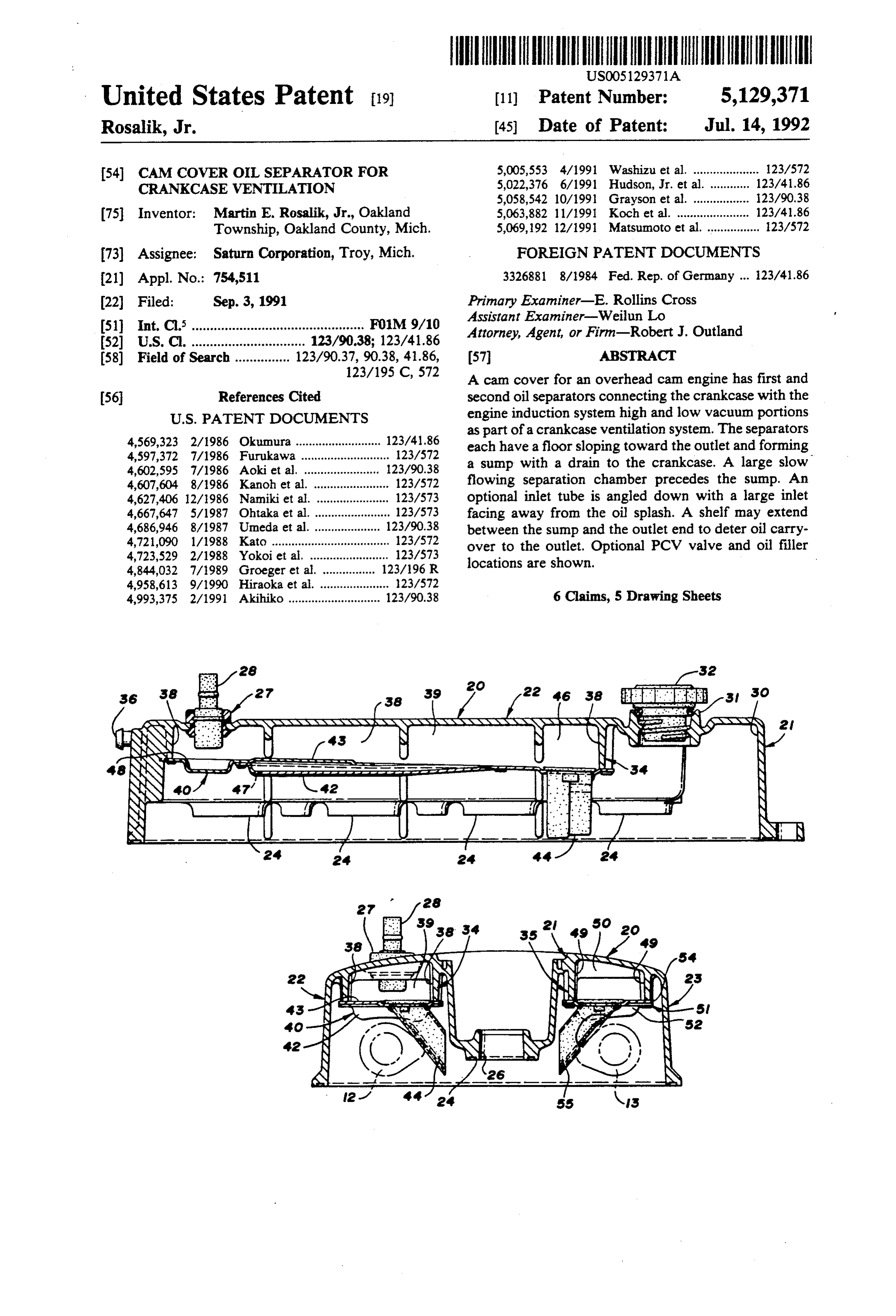
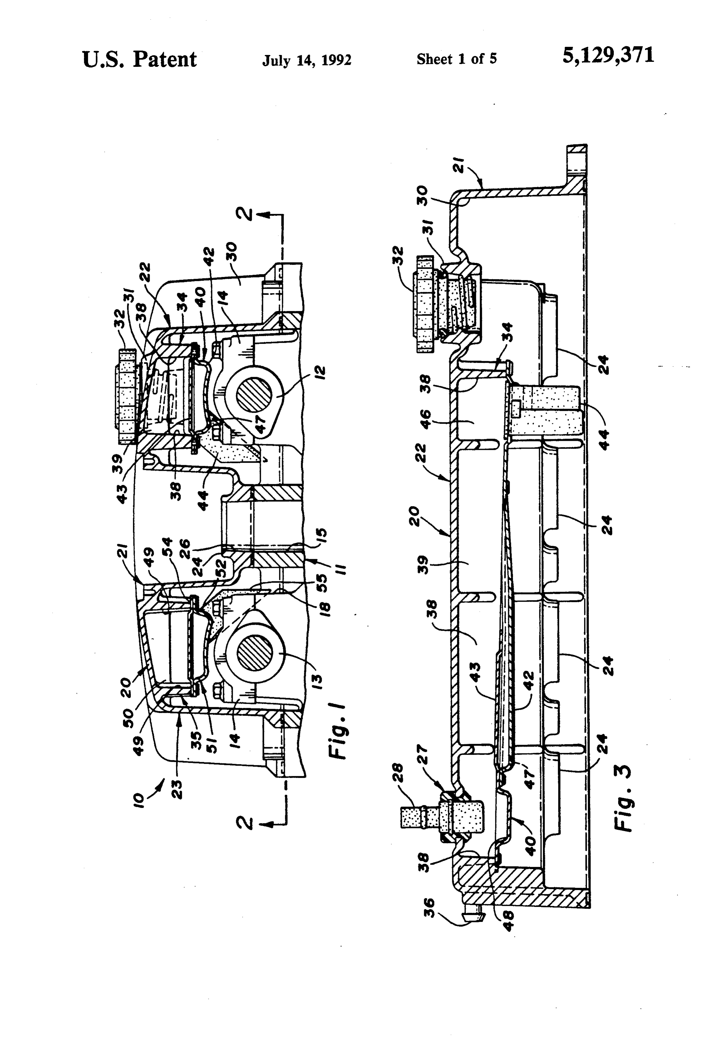
FIG. 1 is a cross-sectional view from the plane of the
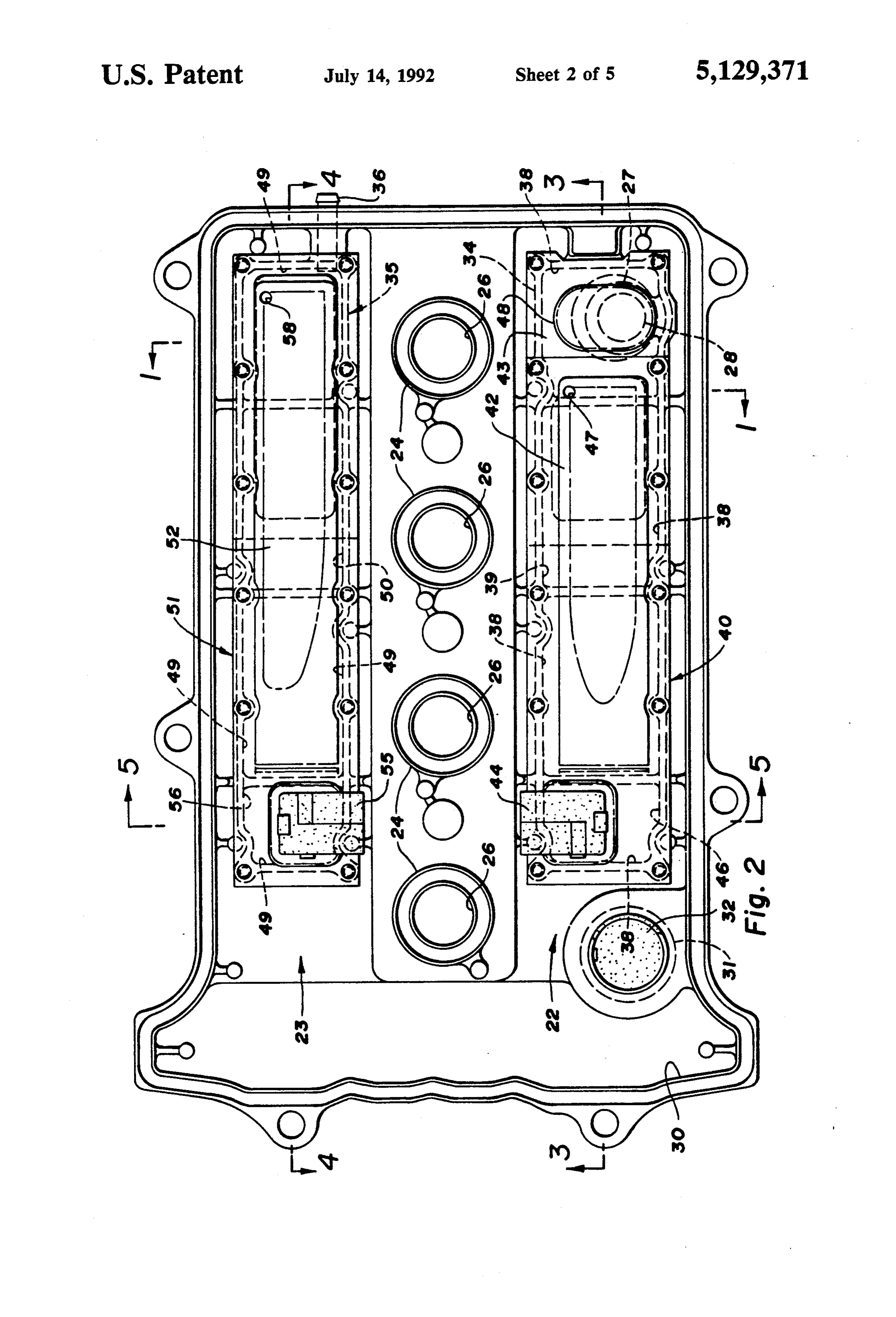
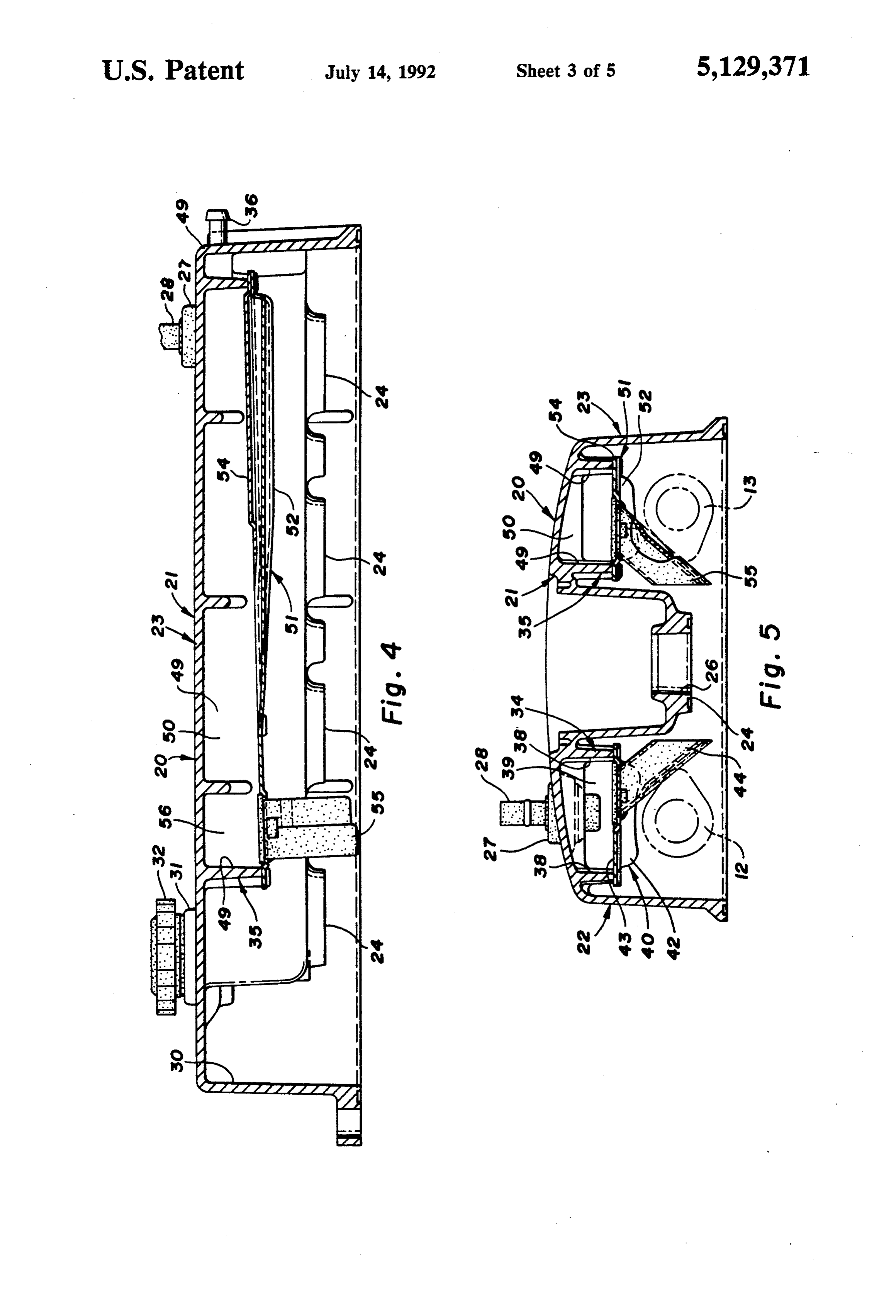
TECHNICAL FIELD 5 line 1-1 of FIG. 2 showing the relation of the cam This invention relates to the crankcase ventilation cover, oil separators, cylinder head and camshafts of a systems of engines of the overhead cam type and partic DOHC FIG. 2 engine;
is a lower plan view of the cam cover from the ularly to oil separators in the cam covers of such en line 2-2 of FIG. 1 showing a preferred embodiment of gines. 10 oil separators according to the invention; BACKGROUND FIG. 3 is a cross-sectional view from the plane of the line 3-3 of FIG. 2 showing a PCV valve associated oil
It is known in the art relating to engines to provide a separator;
crankcase ventilation system with one or more oil sepa FIG. 4 is a cross-sectional view from the plane of the rators in the cam or valve covers. The separator(s) 15 line 4-4 of FIG. 2 showing a low pressure vent con control the carryover of oil from the crankcase to the nection associated oil separator;
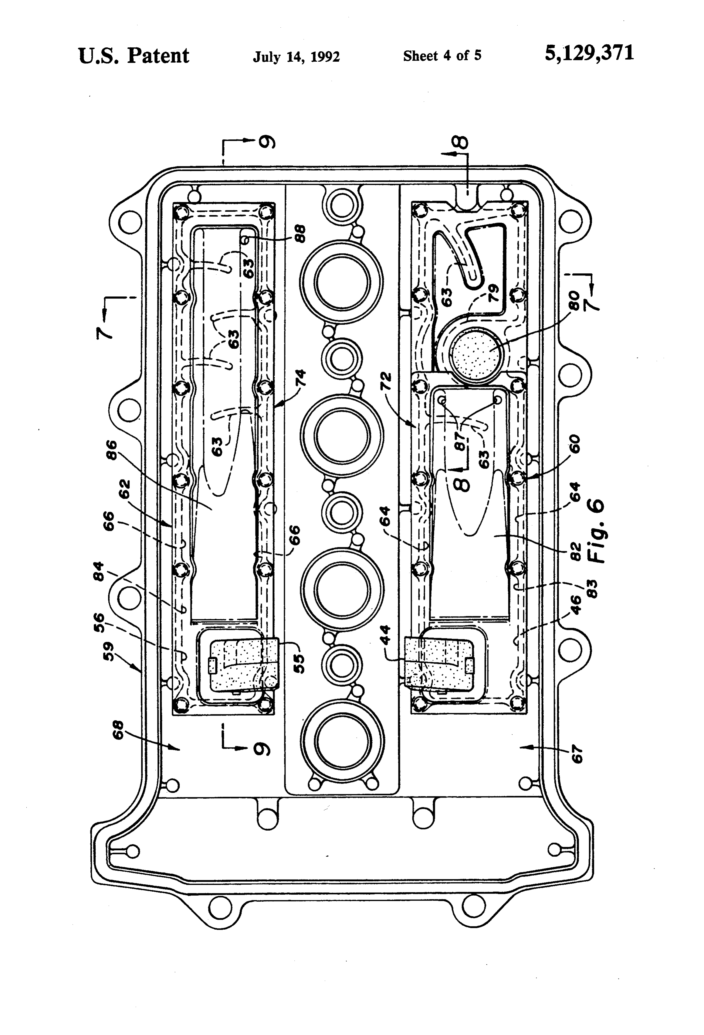
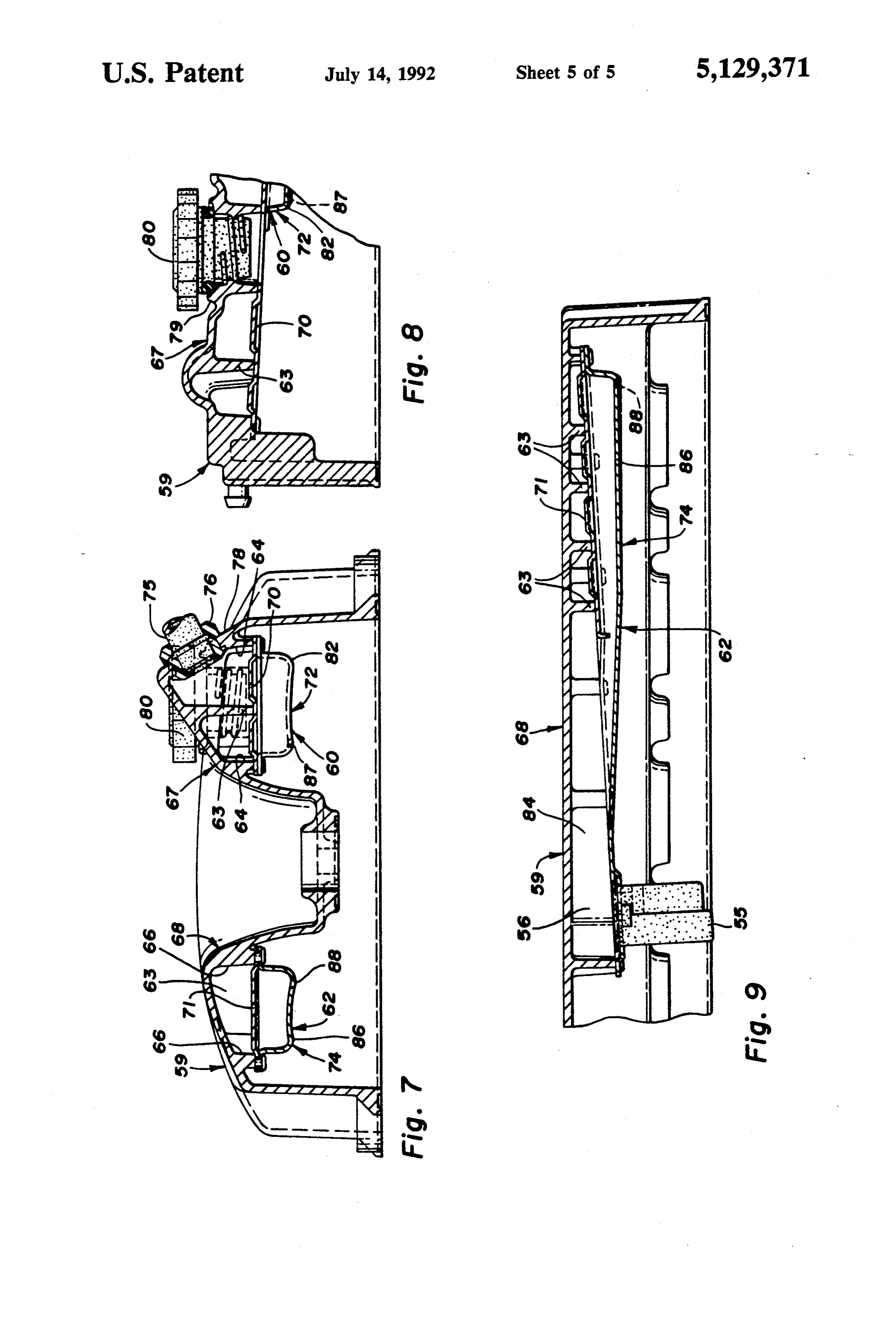
engine cylinders through the positive crankcase ventila FIG. 5 is a cross-sectional view from the plane of the tion (PCV) connections. line 5-5 of FIG. 2 showing the inlet tubes and their In overhead cam (OHC) engines, a large amount of relation with the camshafts of the associated engine; oil is thrown from the camshaft and other moving parts 20 FIG. 6 is a lower plan view similar to FIG. but show in and above the cylinder head, mixing with a turbulent ing an alternative embodiment of cam cover and oil air mass to create a body of rapidly moving air and oil separators according to the invention; droplets and mist. Oil sloshing about the cylinder head FIG. 7 is a cross-sectional view from the plane of the surfaces prior to being drained to the engine sump adds line 7-7 of FIG. 6 showing the PCV valve mounting to the body of active air-oil mixture. 25 and other features;
As a result, the development of a cam cover mounted FIG. 8 is a cross-sectional view from the plane of the oil separator capable of fitting in the available confined line 8-8 of FIG. 6 showing the PCV valve associated space and of adequately limiting the escape of oil from oil separator and oil filler; and the engine through the ventilation system under the FIG. 9 is a cross-sectional view from the plane of the various engine and vehicle operation conditions is a 30 line 9-9 of FIG. 6 showing the low pressure vent con substantial challenge. nection associated oil separator. SUMMARY OF THE INVENTION DETALED DESCRIPTION
The present invention provides an OHC engine cam Referring first to FIGS. 1-5 of the drawings, numeral cover with an oil separator for crankcase ventilation 35 10 generally indicates a double overhead cam (DOHC) that is both simple and compact in construction and yet type of OHN internal combustion engine having a cyl provides efficient separation of oil droplets from the inder block, not shown, with a plurality of cylinders, crankcase gas drawn from the can cover into the cylin not shown, closed by a cylinder head 11. ders of an overhead can engine. The head 11 carries a first camshaft 12 for operating The oil separator is mounted in the engine can cover the dual intake valves, not shown, of each cylinder and and includes a longitudinally elongate chamber with a a second camshaft 13 for operating the dual exhaust crankcase vapor inlet near one end and an outlet to the valve, now shown. Bearing caps 14 are used to retain cylinders in an upper portion near the other end. An the camshafts on the head. The head also includes open and relatively large separation portion adjacent threaded openings 15 for receiving spark plugs, not the inlet extends to a floor sloping downwardly toward 45 shown between the camshafts at the ends of the cylin the outlet end to define a sump with a drain for return ders. Drain openings 18 in the cylinder head allow oil ing collected oil to the crankcase. discharged from the camshaft bearings, valve lifters and Preferably the inlet is through a depending tube with camshaft drive, not shown, to the enclosed areas above a large entrance and positioned to block direct entry of the cylinder head to return to the engine oil pan, not oil droplets thrown from the adjacent camshaft and SO shown.
other moving parts of the engine. A shelf may be pro A cam cover 20 is mounted on the cylinder head 11 vided over the sump toward the outlet end to block and encloses the areas above the camshafts 12, 13 and direct passage from the sump to the outlet. The shelf the camshaft drive. The cam cover includes a housing preferably slopes downwardly toward the inlet to carry 21, which may be formed, as by casting or molding of oil back to the sloping floor and the sump. 55 any suitable material, such as aluminum, plastic or the The chamber may be provided with baffles to in like.
crease the length of the flow path from the inlet to the The housing includes parallel longitudinally extend outlet so that a longer travel will encourage droplet ing raised portions 22, 23 which enclose the area around separation. However, a chamber free of such baffles is the two camshafts. Between the enclosed camshaft ar preferred at present because the slower flow rate result eas, the housing 21 has a lowered section with bosses 24 ing from the enlarged cross section area of the short engaging the head and defining openings 26 for receiv ened path is believed to result in even more droplet ing the spark plugs with clearance for a socket wrench. separation. On the top of the raised portion 22 near one end, a These and other features and advantages of the inven grommet 27 is mounted carrying a PCV valve 28 verti tion will be more fully understood from the following 65 cally in the housing 21 and protruding into the enclosed description of certain specific embodiments of the in area above the camshaft 12. At the other end, adjacent vention taken together with the accompanying draw a cam drive chamber 30, a boss 31 defines a fill opening lings. receiving a fill plug 32.
Page 8
On the end of the raised portion 23 opposite from the shelf 54 slopes slightly downward toward the chamber can drive chamber 30, a nipple 36 is mounted in the end inlet.
wall provides a hose connection extending into an As installed, the first oil separator 34 is normally upper part of the raised portion. connected through the PCV valve 28 to the higher Within the housing raised portions 22, 23, above the vacuum portion of the engine induction system down intake and exhaust camshafts 12, 13, respectively, there stream of the usual throttle valve. The second oil sepa are provided a first oil separator 34 and a second oil rator 35 is normally connected to the lower vacuum separator 35, each formed according to the invention. portion of the induction system upstream of the throttle Though similar in construction, the separators have valve.
sufficient differences to merit their separate description. 10 Under closed and part throttle conditions of low or The first oil separator 34 includes a top wall formed moderate load whereby blow by flow to the crankcase by the top of the housing raised portion 22. Side walls is normally low, the crankcase ventilation flow from the 38, formed by ribs depending from the housing top wall, crankcase is through the first oil separator 34 is the define a longitudinally elongate chamber 39 extending induction system after the throttle with the flow rate above the camshaft 12 from the PCV valve 28 to a point 15 controlled by the PCV valve 28. Make up air is drawn near but spaced from the fill boss 31. The chamber is into the crankcase system from the induction system closed by a floor assembly 40 having a sump portion 42 before the throttle through the nipple 36 and the second and a shelf portion 43. coil separator 35. However, under full open throttle and A generally rectangular inlet tube 44 is mounted in some transient conditions, the blow by flow to the en the floor assembly 40 near the end opposite the PCV gine crankcase may exceed the controlled flow through valve and angles downward past the adjacent camshaft the first oil separator. The excess flow is then directed 12. The lower end of the tube faces away from the through the second oil separator 35 to the induction camshaft to prevent the direct entry of oil droplets and system before the throttle by way of the nipple 36. is cut at an angle to provide an enlarged inlet opening. Thus, both separators 34, 35 are required to perform an The floor 40 extends from the inlet end supporting 25 oil separation function under some conditions although the inlet tube 44 to the outlet end that communicates the second separator 35 is more often used as a path for with the PCV valve. Part of the chamber 39 at and air inlet to the engine crankcase. adjacent to the inlet tube 44 acts as a separation portion OPERATION 46 constituted as an enlarged open space. In this portion the floor is slightly sloped toward the inlet tube al During engine operation, and especially at high though it could be level or otherwise directed. Between speed, a substantial amount of oil is delivered to the the separation portion and the outlet end, at least part of engine camshaft bearings and hydraulic valve lifter the floor slopes slightly downward toward the outlet and/or other moving parts of the valve gear in the end to form the sump portion 42 having its lowest point upper portion of the cylinder head. The oil is thrown off near but short of the PCV valve location. A small drain 35 by the rotating camshafts and further mixed with the air opening 47 is provided at the low portion of the sump. which is made turbulent by the motion of the moving Part of the floor 40 extends beyond the sump under parts as well as by the flow of crankcase gas into the the PCV valve and may include a shallow recess 48 to crankcase ventilation system. The oil separators operate clear the end of the valve. This portion is preferably in the following manner to remove from the air passing formed integral with the shelf 43 that extends over the through them a large amount of the entrained oil which sump for about half the length of the sloping floor por would otherwise be exhausted into the engine intake. tion. The shelf and the connected floor portion under The optional inlet tubes 44, 55 are positioned with the the PCV valve preferably are sloped slightly down enlarged angled opening away from the direct path of ward toward the inlet end of the chamber. oil thrown from the camshafts and other parts and at The second oil separator 35 is similar, having a top 45 points of relatively lower turbulence. This minimizes wall formed by the top of the housing raised portion 23, entry of oil into the separators as does the enlargement side walls 49 formed by ribs depending from the hous of the inlet opening which allows an initial slow rate of ing top wall to define a longitudinally elongate chamber inlet flow.
50, a floor assembly 51 having a sump portion 52 and a From the inlet tubes, the air passes into the separation shelfportion 54. A generally rectangular inlet tube 55 is SO portions which have larger flow area to slow the flow mounted in the floor assembly 51 near the end opposite and allow oil droplets to coalese and settle out on the the nipple 36 and angles downward past the adjacent floors of the separators. Here, the direction of air flow camshaft 13 with an angled lower inlet end facing away urges the oil along the floor and down the sloping por from the camshaft to deter entry of oil drops and pro tions to the sumps 42, 52, where it collects and passes vide an enlarged inlet opening. 55 through the drain openings 47, 58 to the cylinder head The floor 51 extends from the inlet end at tube 55 to for return to the crankcase via drain openings 18. an outlet end that connects with the nipple 36. Part of The oil freed air passes along the upper portions of the chamber 50 near the inlet tube 55 acts as a separation the separators to the outlet ends where it exits through portion 56 formed as an enlarged open space wherein the PCV valve in separator 34 or the nipple in separator the floor is optionally sloped slightly toward the inlet 35. The shelf portions 43, 54 located between the sumps tube 55. Between the separation portion and the outlet and the upper portions at the outlet ends of the separa end, part of the floor slopes slightly downward toward tors help prevent oil in the sumps from being re the outlet end to form the sump portion 52 having its entrained in the exiting air by the turbulent conditions lowest point near the end below the entry of the nipple or by the centrifugal force of driving maneuvers which 36 into the chamber 50. A drain opening 58 is provided 65 urge the collected oil toward one or the other ends of at the lower point of the sump 52. The shelf 54 extends the respective separator.
over the sump from the end below the nipple for about When the engine is shut down in a level position, the half or two-thirds the length of the sloping floor. The oil on the sloping shelves drains to the floors and thence
Page 9
to the drains for return to the crankcase while oil in the the full scope permitted by the language of the follow separation portions may run out through the inlet tubes ing claims.
or along the sloping floors to the drains. What is claimed is:
1. An engine cam cover for an engine having a longi
ALTERNATIVE EMBODIMENTS tudinal overhead camshaft, the cam cover having an FIGS. 6-9 show an alternative embodiment of cam internal oil separator for crankcase ventilation gas flow, cover 59 having a first oil separator 60 and a second oil said separator comprising separator 62 having features according to the invention. a side wall and a floor cooperating with a top wall of The arrangements are similar to the cover 20 and oil the cam cover to define a longitudinally elongate separators 34, 35 previously described but differ in cer O chamber in an upper portion of the cam cover tain aspects noted below. adjacent the camshaft;
In cover 59, the separators 60, 62 include cast-in ribs an inlet opening to the chamber longitudinally near 63 extending from the side walls 64, 66 to form laby one end for communication of the chamber with rinths in the upper portions of the raised portions 67, 68 the cover interior generally adjacent the camshaft above the shelf portions 70, 71 of the floor assemblies 15 location as installed, 72, 74. The PCV valve 75 and its supporting grommet an outlet opening from the chamber longitudinally 76 are mounted at an angle in a sloping roof portion 78 near an opposite outlet end and in an upper portion of the raised portion 67. The oil fill boss 79 and fill plug adjacent the top wall to allow the discharge of 80 are located adjacent to the PCV valve with the filler crankcase gases, opening extending through the floor 72. Air flow to the 20 the chamber including a separation portion of rela valve 75 thus passes around the boss 79 which acts tively large flow area near the inlet for encourag similar to another rib 63 in the upper section of the ing the collection of oil droplets on the floor, separator 60. Because of the filler location, the sump the floor having a portion sloping gradually down portion 82 of the first separator 60 is shorter than the wardly toward the outlet end of the chamber and comparable sump 42 of the first described embodiment, 25 defining a shallow sump for oil collection in a but it operates in a similar manner though with a smaller lower portion toward the outlet end, and, storage volume. a drain in the sump toward the outlet end to return The inlet tubes 44, 55 and the separation portions 46, collected oil to the cover interior and to a con 56 of the separator chambers 83, 84 are like those of the first embodiment, but the floor assemblies 72, 74 differ 30 2. nected engine crankcase. in having somewhat higher slopes to the sloping walls comprising a tubecan
An engine cover as in claim 1 and further of the sump portions 82, 86 and shelf portions 70, 71. adjacent the location of an from extending the inlet downwardly associated moving engine
The amount of slope is variable depending upon the part and shielding the inlet against the direct available height of the cover raised portions and the droplets thrown from said moving part, the entry tube of oil being camshafts and other gear covered thereby. A slope of of relatively large flow area at its entrance to minimize
three to five degrees is probably more effective but a slope as low as one degree should provide an advantage the entrainment of oil droplets in the entering gas over a level floor or shelf in aiding the draining of col Streal. 3. An engine cam cover as in claim 1 and further lected oil. One or more drain openings 87, 88 are pro comprising a shelf extending over the sump toward the vided at the outlet end of each sump 82, 86 as in the first outlet end and separating the upper and lower portions described embodiment. of the chamber toward the outlet end to restrict the In the various embodiments, portions of the floor carryover of oil from the sump to the outlet. extend closely above the associated camshafts 12, 13 so 4. An engine can cover as in claim 3 wherein the that some of the floor may need to be horizontal rather shelf slopes generally downward the inlet end to drain than sloped as desired. However, the floor may be 45 wrapped around the upper portion of the camshaft to oil collected thereon back onto the lower wall for deliv provide clearance but allow the outer edge or edges of ery to the sump.
the floor to include the desired slope toward the sump chamber 5. An engine can cover as in claim 2 wherein the and the outlet end of the respective separator chamber. is free of baffles that interfere with direct flow While the invention has been described by reference 50 from the inlet to the outlet, to certain preferred embodiments, it should be under 6. An engine cam cover as in claim 2 wherein the stood that numerous changes could be made within the chamber includes a plurality of baffles that alter the spirit and scope of the inventive concepts described. flow path from the inlet to the outlet to increase its Accordingly it is intended that the invention not be length. is limited to the disclosed embodiments, but that it have 55
Provenance
- Collection
- Cited prior art
- Original PDF
- patentimages.storage.googleapis.com →
- Filed
- 1991-09-03
- Pages
- 9
- Method
- pdftotext (the PDF's own text layer) + pdftoppm 300dpi page scans
- Source
- Google Patents bibliographic record
- Granted
- 1992-07-14
- Inventors
- Martin E. Rosalik, Jr.; Saturn Corp
- Transcribed from
- patentimages.storage.googleapis.com →