patent · US2595941
Cable-mounted flight conveyer
6 May 1952
Page 1
Drawing sheet — no readable text.
Page 2
Drawing sheet — no readable text.
Page 3
Patented May 6, 1952
UNITED STATES PATENT OFFICE
CABLE-MOUNTEED FLIGHT CONVEYER.
Henry W. Hapman, Detroit, Mich., assignor, by mesne assignments, of forty per cent to Hannah
J. Hapman, Detroit, Mich.
Application September 4, 1948, Serial No. 47,913
This invention relates to conveyors and, in reach out on a bend in the conveyor conduit, fill particular, to flight conveyors of the cable type. ing the space, as the flight is pulled toward the One object of this invention is to provide a bend so as to scrape or wipe the conveyed ma cable-mounted flight conveyor having flightS terial from the Walls of the bend since the flight preferably of rubber-like material, wherein the is normally pulled toward one side of the bend. cable between the flights is covered by Springs Another object is to provide a cable-mounted and rubber-like sleeves extending between flight conveyor of the foregoing character which the flights and arranged in such a manner that is especially well-adapted to travel at unusually the flights, which are loosely mounted on the high speeds and wherein the Springs intercon cable, can move slightly along the cable So as to 0. necting the flights transmit the load from flight compensate for the stretch of the cable and still to flight to the connectors between Successive maintain the covering thereof. lengths of cable, the cable itself at high Speeds Another object is to provide a cable-mounted resisting bending and springing outward in mak flight conveyor of the foregoing character where ing a turn-unlike a conveyor chain which by its in the sleeves between the flights are slightly 5 limpness hugs the inner side of the bend. longer than the estimated distances between suc In the dra Wings:
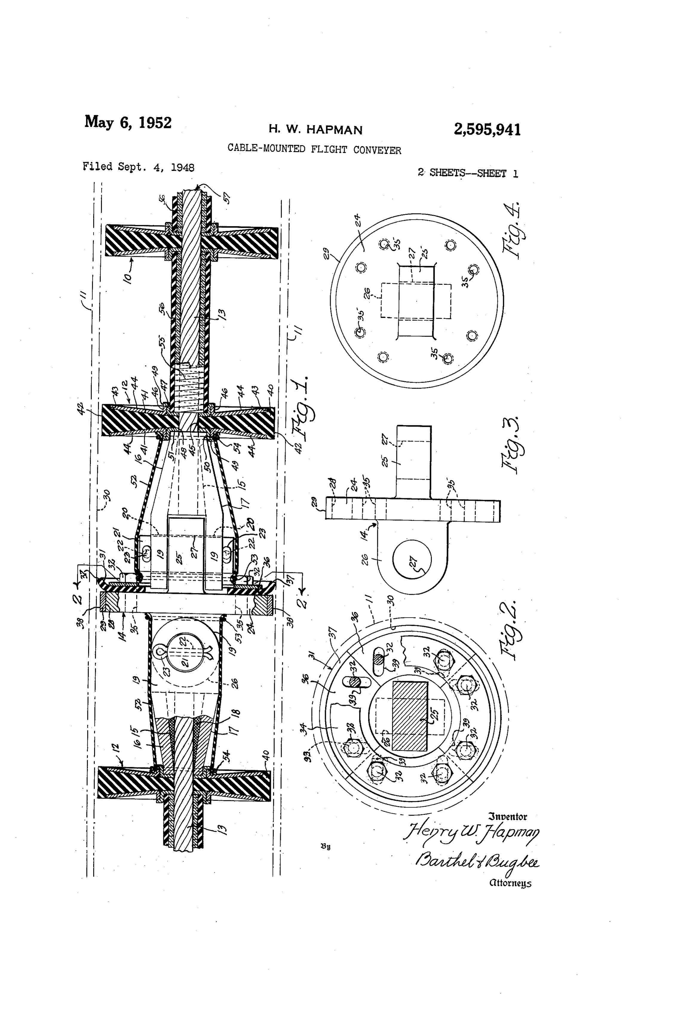
cessive flights, so that both the springs and the Figure 1 is a central longitudinal Section sleeves must be slightly compressed during the through a cable-mounted flight conveyor, accord assembly of the conveyor, thereby still further ing to a preferred form of the invention, show insuring that the cable will remain covered even 20 ing one of the connectors between successive though it stretches during use. lengths of cables;
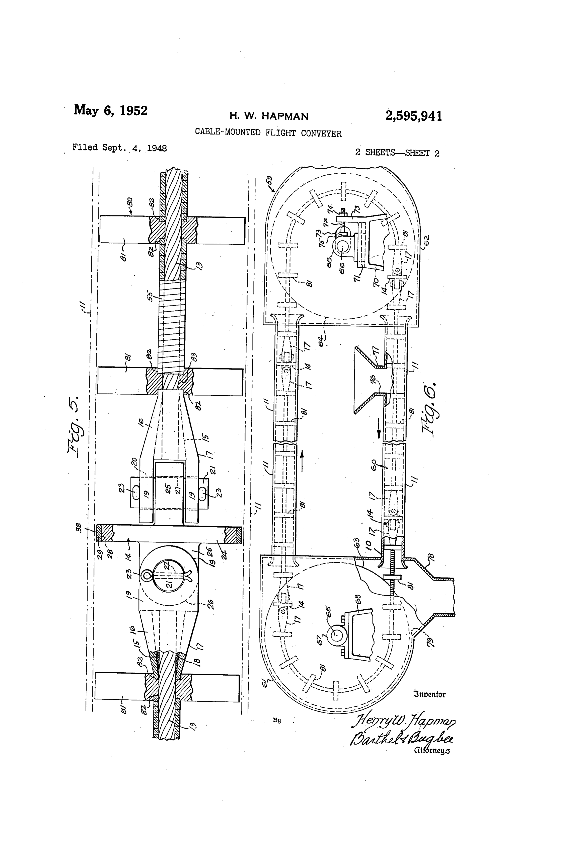
Another object is to provide a cable-mounted Figure 2 is a cross-section along the line 2-2 fight conveyor of the foregoing character where in Figure 1, showing details of one of the cable in a predetermined number of flights are a S connectors and the wiper associated therewith; sembled, with their spacing Springs and cover 25 Figure 3 is a side elevation of a connector re ing sleeves, on predetermined lengths of cable, moved from the cable and its end clevises; having connectors at the end of each length Figure 4 is a front or end elevation of the cou whereby the Successive lengths, which are cou pling shown in Figure 3;
pled together to form an endless conveyor, dis Figure 5 is a side elevation, partly in central tribute the stretch. 30 vertical section, of a portion of a modified cable Another object is to provide a cable-mounted mounted flight conveyor adapted to withstand fight conveyor of the foregoing character where high temperatures and lacking the rubber-like in the couplings between successive lengths of protective coverings of the conveyor shown in cable are likewise covered with rubber-like ma Figures 1 to 4 inclusive; and terial so that the conveyor as a whole is free from Figure 6 is a side elevation, partly in vertical exposed pockets or crevices in which conveyed section, of a flight conveyor installation adapted materials might lodge, thereby well adapting the to employ the conveyors shown in Figures 1 to 5 conveyor for use in conveying food products, inciusive.
chemicals or other materials in which the lodg General arrangement ing of such particles would be liable to cause de s he conveying of the finely divided materials cay, disease orf unsanitary conditions. at high speeds by ordinary conveyors has hitherto Another object is to provide a cable-mounted presented Serious problems, particularly Where flight conveyor of the foregoing character where naterials conveyed were of a perishable nature, in the connectors of Successive lengths of cable Such as four, or other food products. Conveyor have annular flanges which cause them likewise 45 chains having flightS mounted thereon fre to serve as flights, these fianges being preferably quently do not adapt themselves well to the encircled by bands of non-ferrous metal Such as rounding of bends in the Conveyor conduit at high braSS, So as to avoid the striking of Sparks. Whenspeed, since the conveyor chain by its limpness the conveyor is mounted in a steel conduit, there tends to hug the inner Wall of the bend. Fur by preventing the danger of explosions which is : thermore, the conveyor in rounding a bend often frequently present in the conveyor of Such ma leaves material deposited on the Walls at one side terials as flour or grain. of the bend. Conveyor cable stretch is also a Another object is to provide a cable-mounted serious problem in previous conveyors, causing fight conveyor of the type set forth in the ob the cable to be exposed if the cable is covered ject immediately preceding, wherein the coin by sleeves.
nector flanges are also provided with peripheral The present invention Solves these problems by wipers of disc form and of rubber-like material forming the conveyor in a series of separate Oi", optionally of brush form or of Spring steel or lengths of cabie interconnected by special cou wire brush construction, these wipers being plings, thereby distributing the stretch between slightly larger in diameter than the flanges so as 60 successive lengths of the conveyor and limiting to project beyond the periphery thereof and the amount of motion of the flights due to this
Page 4
stretch. The fights themselves, which are pref in diameter than the pivot pins 2 (Figure 1) erably of rubber-like material, such as synthetic so that a “sloppy fit' is obtained between them. rubber, are loose upon the lengths of cable on This imparts a self-alignment between the parts which they are mounted, and are assembled be which is very helpful during the operation of the tween slightly compressed sleeves and helical conveyor, particularly as it passes around the Springs. These Springs, which are closed up, driving pulley.
transmit the drive from one cable coupling to The arms 9 of the clevises 7 are of such spac another. Wipers of rubber-like material, spring ing and the lugs 25 and 26 of Such thicknesses that the two will fit closely together as shown in steel or wire brush material, are attached to flanges which project from the cable couplings 10 the central portion of Figure 1. Since the cou to form flights in themselves, the couplings be plings 4 are ordinarily of ferrous metal, Such ing surrounded by annular bands of braSS Ol' as Steel, for purposes of strength and low cost, other non-ferrous metal, so that no Sparks Will their peripheral edges or rims 22 are preferably be struck during the paSSage of the flight Con encircled by annular bands 29 of non-ferrous veyor through a sealed conveyor conduit. This metal, such as brass. The bands 29 are prefer provides a high-Speed flight conveyor having no ably Sweated on the rims 28 so as to be securely exposed pockets or crevices in which food croth attached thereto, and serve to prevent the throw er conveyed materials can lodge, and which ing off of Sparks on contact with the inner walls brushes or Scrapes off the conveyed ilaterial of the conveyor conduit during operation. which would otherwise adhere to the Walls of 20 This precaution minimizes the danger of explo the conveyor conduit at bends therein. Sions arising from Such sparks when explosive or inflammable materials are being conveyed or the
Conveyor construction Conveyor paSSes through atmosphere laden with Referring to the drawings in detail, Figure 1 explosive dust, vapor or gas. shows a portion of a flight conveyor, generally The overall diameter of the coupling 4 includ designated ), according to a preferred form of ing its brass band 29, is approximately the same the invention, as mounted in a conduit of Steel as the diameters of the flights 2 so that the cou or other Suitable material. The conduit. nay pling also Serves to Some extent as a flight. In be arranged in any shape of path, depending upon Order to wipe, Scrape or brush off conveyed mate the particular installation, as the invention is not 30 ria. Which otherwise would adhere to the inner limited to any Specific path Such as U-Shaped, V walls. 30 of the conduit f f, particularly in the shaped or the like. It is contemplated that the vicinity of bends therein, the couplings 4 are conveyor emerges from the conduit for a provided with wiper or scraper units 3 secured Short portion of its run SO as to pass around thereto as by the bolts 32 passing through the resilient frictional driving devices Such as are 35 holes 33 in annular washers 34 and threaded into shown in the Hapman Patents Nos. 2,326,535 of hreaded holes 35 (Figures 1 and 4) arranged in August 10, 1943, and 2,333,926 of November 9, pairs near the periphery of the disc portion 24 1943. This type of driving nechanism as ShoWin of the couplings 4.
in these patents, unlike a chain conveyor, is in The wiper or scraper units 3 preferably con dependent of pitch, and the stretch of the cable 40 sist of arcuate or quadrant shaped members 36 of makes no difference in the operation of the con rubber-like material, such as Synthetic rubber, veyor since it is automatically taken up by the having their peripheral edges 37 arranged on driving mechanism shown therein. larger diameters than the rim or periphery 38 The flight conveyor consists generally of of the brass band 29 forming the outer edge of flights 2 loosely mounted on cables 3 which the coupling disc 24. In this way, the wiper or are connected to one another by connectors or scraper unit 3-f projects beyond the edge of the couplings f4. The cables 3 are of predeter coupling 4 (Figure 1) so as to engage and wipe mined length, Such as, for example, ten or or scrape off any material adhering to the inner tWelve feet, and are of any suitable material, such Wall of the conduit . The arcuate members 36 as Steel Wire laid in twisted Strands in the usual are provided with paired elongated slots 39 Inanner. The ends of the cables 3 are in through Which the shanks of the bolts 32 pass and Serted in the conical recesses inside the fer Which permits the arcuate members 36 to be rules 6 of the clevises 7, lead or other suitable moved outward or inward slightly in order to material 8 being flowed into the recesses 5 in overconne or take up wear as well as to adjust the a molten condition to fill in the Space between 5 5 amount of force or friction with which the wiper the wall of the recess 5 and the outer surface unit 3 engages the conduit's inner wall 30. Of the cable 3, as shown at the left-hand side of Under Special conditions, such as in conveying Figure 1. When the molten metal solidifies, the tlallSually adherent or tenacious materials, Such cable 3 is securely locked inside the ferrule 6. aS, for example, zinc oxide, the Wipers or scrapers Each ferrule 6 has parallel arms 9 projecting 60 3 may optionally be made of Spring Steel or in forward from its end, these arms being provided the form of wire brushes. The harsher action of with aligned bores 20 for receiving a pivot pin 2 these metallic wipers or scrapers prevents the having cross drilled holes 22 at its opposite ends deposition of the zinc oxide which would other for the reception of suitable fasteiners, such as wise coat the inside wall 3 of the conduit with cotter pins 23. Successive layers of material. The Scrapers or The arms 9 of the clevises 7 of separate cable Wipers 3 by being mounted on the couplings 4, lengths 3 are interconnected by the couplings Satisfactorily perform their wiping or scraping 4 through the pivot pins 2. The couplings 4 actions yet at the same time do not create the (Figures 3 and 4) are in the form of cast steel friction. Which would otherwise occur if the discS 24 having lugs 25 and 26 projecting from Scrapers were mounted directly on the flights 2. their opposite sides in planes at right angles to The fights 2 under these circumstances, are One another, the lugs 23 and 26 having bores 27 made with a liberal clearance between their outer therein for the reception of the pivot pins 2 . peripheries and the inner wall 3 of the conveyor It will be seen that the holes 20 and 27 in the conduit i?, Such as a quarter inch difference in clevis arm 9 and coupling lugs 26 are larger 7 5 diameter for a six inch conveyor conduit. These
Page 5
clearances, however, are purely relative and may ample, the reinforcement members 44 of the be varied according to the kind of material being flightS 2, the retaining rings 54, the sockets 47, conveyed or other conditions in the conveyor in the couplings A, the bolts 32 and washers 34 may Stallation. be made of such corrosion-resistant material, and The flights 2 consist of discs #3, preferably the brass rings or bands 29 may be omitted en of rubber-like material such as rubber or syn tirely except in conveying particles of material thetic rubber, Such material being known gen Which involve an explosion hazard or where the erically as elastic deformable material. The flight Conveyor paSSes through explosive materials or discs 40 preferably have inwardly dished or ap atmospheres. - proximately conical side walls 4 having their 10 Conveyor operation outer edges spaced away from the peripheral sur In the Operation of the invention, let it be as face 42 thereof and with a shoulder 33 defining Sumed that the cables 3 have been connected in their outer limits. The shoulders S3 serve to re an endless path so that they form an endless flexi ceive the Outer edges of shallow dished or coin ical Side plates or reinforcement members A4 15 ble propelling unit 57 consisting of the cable lengths 3, couplings 4 and the clevises as which are bonded to the flight discs 40 during the shown in Figure 1. Let it also be assumed that molding process by which the latter are made. the flights 2 have been assembled on the con The flights 2 are cupped on their opposite sides Weyor cables 3 With the springs 55 and sleeves in this manner to assist their carrying loads on 56 in slightly compressed condition. Under these Vertical runs, such as in grain elevators. The 20 circumstances, the central walls 5 of the sockets centers of the flight discs 4 are provided with 4. are pressed Snugly up against the adjacent holes 45 Which fit, loosely over the cables 3 So as ends of the ferrules 6 of the clevises . When to be slidable therealong. There are no restric the driving mechanism is started, such as for ex tions on the cables 3 except at the connectors of couplings 4 and not at any point in between these 25 ample the driving mechanism shown in the Hap
couplings ff.
The reinforcement, members is is are provided to above, the flight conveyor travels in an with central flanges 46 which snugly engage the Orbital path depending upon the path formed by outer walls of sockets or cups 37 which likewise the conveyor conduit ff. The driving mechanism frictionally engages the peripheries of the fights have central holes 48 locsely fitting the cables 30 f2, the sockets All of which press upon either the 3. The Sockets Ai are not bonded to the rubber. ends of the ferrules 6 of the clevises or upon like flight discs A, but may be inserted or the ends of the springs 55, transmitting the thrust removed at will. The sockets 4 have marginal to the coupling 4 which is ahead of the fights flanges A9 which engage the edges of the flanges f2 being engaged by the driving mechanism. The 46 on the reinforcement members A4, axial flanges fact that the Springs 55 are of Square cross-sec 58 Which are engaged by the flanges 33, and cen tion gives an adequate bearing surface to trans tral walls 5 having the central holes 48 there mit a heavy load. Thus, as each flight is engaged in for the passage of the cables 3. In order to by the resilient pulley walls of the driving mecha conceal the joints between the couplings 4 and the flights 2, tubular covers 52 of rubber-like ma 40 nism, the thrust is transmitted to the Spring ahead of it and this, in turn, pushes against the flight terial and elongated CrOSS-Section aire Stretched ahead of that Spring and so on until the thrust between the couplings 4 and the discS 2 and Se reaches the first coupling it ahead of the fights cured thereto by clamping rings 53 and 5é respec being engaged by the driving mechanism. The tively. This construction prevents particles of coupling, in turn, pulls on the cable length 3 con the conveyed material from reaching the now nected to it, transferring the pull back to the cou ing parts associated with the couplings , and pling behind it and the flights being engaged by thereby maintains the conveyor is in a sanitary the driving pulley. The lengths of the cables Condition. f3 are such as to be long enough to have at least In order to drivingly interconnect the various one length capable of passing entirely around the flights 2 between successive couplings i, the portion of the pulley engaged by the fights, and fights 2 are spaced apart from one another by leaving a length to spare. helical springs 55 preferably of square cross-sec On a straightaway run of the conveyor, the tion. These springs 55 likewise fit, loosely over Springs 55 are required to sustain the load only the cables 3 and are assembled in a slightly con pressed condition between successive flights 2 SQ 5 5 of the material being conveyed. When each Spring 55 reaches a pulley or a bend in the con as to be able to expand to take up a certain duit, the spring convolutions are forced tightly amount of cable stretch. The opposite ends of together on the inside of the bend but expand the springs 55 are seated in the sockets 4, and slightly and Separate slightly on the outside are covered by sleeves 56 of rubber-like material, thereof, so as to traverse the bend successfully. Such as Synthetic rubber, likewise seated in the 60 Thus, on the inside of the bend, the Spring 35 sockets 4 between the springs 55 and flanges 53. acts like a solid tube. The springs 55 prevent, The sleeves 56 are likewise assembled in a slightly kinking which destroys ordinary cables, and main congressed condition, like the springs 55, So as to tain the cable in a taut condition, as well expand When cable stretch occurs. It Will be as to transmit the drive. Thus, the Springs 55 understood, however, that neither the flights 2 ably occurs in the cable lengths 3, whereupon nor the springs 55 are claraped to the cables 3, the flights 2 nove slightly along the cable 3, but are capable of sliding slightly along the cables making their own adjustinent to the changed 3 as stretch occurs or as such self-alignitient is length of the cable between successive couplings called for under operating conditions. 4. All cables stretch to Some extent, especially The flight conveyor of this invention lay be 70 in their early life and the present conveyor takes further protected from the action of corrosive up this stretch as it occurs. As the conveyor goes foods,-chemicals or other such materials by mak around the drive pulley, the cables 3 make their ing the only exposed metal parts of stainless steel own adjustment and pull outward, increasing or other corrosive-resistant material or of coating the diameter of contact on the drive pulley. or plating them with such a material. For ex 5 Moreover, the flights 2, Springs 55 and spring
Page 6
covers 56" are also free to rotate on the cable atter and the bearing bracket 88 in their ad lengths f3. So that there is no restriction what justed positions. An elongated slot 75 permits ever on the cable lengths except at their couplings this adjustment of the shaft 66. 4. in Order to fill the conduit 69 with material to In high Speed operation, the cables 3 resist, 5 be conveyed, the latter on its upper Surface is bending and tend to move outward in making a supplied with an opening 3 to which a funnel turn, unlike a conveyor chain, which by its limp like inlet hopper i is connected. A funnel-like ness hugs the inner side of the bend. Thus, even outlet hopper 8 is also connected and extends though the Wire Springs 55 are closed tightly on downward from an opening 9 in the bottom of their inner sides at the bends, they will Still O the housing 62. Thus, if the pulleys 63 and 64 stretch around the turn but at the same time will are rotated in a clockwise direction, the flight always remain tight on a straight run of the Con conveyor 3 in the lower conduit 69 will move veyor. Moreover, the present conveyor not only from right to left, conveying material from the occupies much less space than a bucket conveyor, inlet hopper 7 through the conduit 68 and into but can be operated at a much higher speed with the housing 32, where it drops off the conveyor out danger of breakdown. :9 and dres do wivyard through the outlet hop Furthernore, as the couplings : traverse bends per 8 into any suitable receiver. It will be ob in the conveyor conduit , the Wipel's Oi Scagei'S served froii Figi's 6 that the conveyor installa 3 reach out and fill the Space Since the flight it tion 39 inci fles saveral lengths of the cables 3 self is pulled toward the bend. The Wiping ac and several of the couplings & interconnecting tion is Such as to wipe off or Scrape off material their adjacent, ends. This construction confines which would otherwise collect, at the bends. In the Stretch of the cable to each ength thereof this manner the food or other material conveyed and limits the aincunt, that any One fight can finds no pockets in which to collect, hence the travel along the Cable.
conveyor and its conduit are inaintained in a Solid tricciered flight CO72eyor completely sanitary condition. As Wear occurs on The raagiiied flight conveyor, generally desig the wipers or scrapers 3, they can be readjusted 2ated 89, showin in Figure 5, is as regards the to engage the conduit Walls as tightly as desired cable, the Springs aind the couplings, similar to the merely by loosening the bolts or screws 32 and the principal forms of the invention shown in Fig moving the arcuate members 33 outward, retight lures 1 to 4, inclusive, hence Similar parts are ening the bolts 32 when this has beein accom similarly designated. The modified conveyor 80, plished. The conveyor is thus self-cleaning, op however, is adapted for use in conveying materials erates at high speed and is independent of pitch at high temperature where rubber would disinte changes or cable stretch. Since the cables 3 grate or be seriously damaged. One typical in are in separate lengths, the stretch is confined 3 5 stallation, for example, is that of handling char, to the individual lengths, rather than to a Single which is coal fron which a portion of the Volatile length of cable forming the entire propelling unit ingredients have been separated, but which has 3, as in prior installations. not been reduced to coke.
Conyegor iniStaliation. The modification of Figure 5 has solid flights Figure 6 shows a typical fight conveyor instal {{ in place of the coin posite, partially Synthetic lation in connection with which the flight con rubber flights of Figure 1. The flights 8, for ex veyor of Figures 1 to 4 inclusive and the modified ample, Inay be made of cast iron or other Suit flight conveyor of Figure 5 described below, are able material and have Sockets or counterbores adapted to be used. The fight conveyor installa 32 at their cential portions opening into bores 33 loosely receiving the cable i3. The ends of tion generally designated 53 consistS, in addition 45 the to the conduit, , of a lower conduit 60 and end SpringS 55 are received in the counterbores housings 8 and €2 cgintaining the driving and 32 in place of the sockets 4, which are omitted idler pulleys 83 &nd 63 Younted on shafts 65 and in this modification. The ends of the ferrules 6 journaled in bearing bracketS 6 and 6 are also received within the counterbores 22 68 mounted on supports 69 and it. The Sup of the adjacent fights 3.
ports 63 and 3 are, of course, nouinted on The operation of the modified flight conveyor the floor or upon earns or other portions of a 39 is Substantially the same as that of the prin building structure, the details of which are cipal for in shown in Figures 1 to 4 inclusive, ex not involved in the present invention. The 5 5 is cept that the Working course of the conveyor 80 pulleys 63 and 64 are of the type disclosed and arranged in a Straight line as shown at the claimed in the Hapnan Patent No. 2,326,535 bottoli of Figure 6. Without the covers 56 for of August 10, j943, and hence require no de the Springs 55, conveyed material in powdered tailed description. Power is applied to one of forii) Would pack in the intervals between con the shafts 65 or 63, preferably to the shaft 65, volutions Cf the Spirings if these passed around whereupo the rotation of the pulley 63 and its 00 ets beinds in the conduit or around pulleys or sprock engage:Rent with the fight conveyor 9 cause while they were conveying such material. the latter to travel in all orbital path through
On a Straightaway course, however, the con the housings and 82 and the conveyor con volutions of the Springs 55 do not separate, hence no material can pack into these spaces as duits and €3. The bearing bracket S is, for the Springs are tightly coiled by overstressing purposes of illustration, bolted to the Support theim.
S3, whereas the bearing bracket S3 is slidably AS before, the raterial to be conveyed is de imounted in a grooved guideway forined in the posited in the inlet hopper 77 whence it drops Support 3 in order to provide means for taking through the hole i3 into the conduit 68 (Figure up the slack in the conveyor it. This is done 6). Here it is picked up by the ?lights a as they by tightening or looseniing adjusting screws i2 are pulled along by the cables i3 through the rotatably secured as at 3 to the bearing bracket action of the couplings f4 and springs 55, as ex 63 and passing through a bore in an arm 3 pro plained in connection with the operation of the jecting upward from the support 3. Nuts 75: principal form of the invention. When the con threaded upon the ScieWS 2 serve to hold the Weyed material reaches the left-hand end of the
Page 7
conduit 60, assuming the pulleys 63 and 64 to be over said couplings and concealing parts thereof. driven in clockwise directions, the material drops 8. A flight conveyor comprising a plurality of out of the spaces between the fights 8 and cable couplings, a plurality of cables attached passes down through the hole 79 into the dis at their ends to said couplings, a multiplicity charge hopper 8 and thence into a suitable re of flights of elastic deformable material and ceiver. Thus, the flights are freed from the con having concave opposite sides loosely and slid veyed imaterial as they pass around the pulleys ably mounted on said cables, dished side plates 63 and 64, hence either the spring sleeves 56 or disposed in mating engagement with Said con the covers 52 can safely be omitted in this modi cave opposite sides of Said flights, and helical fication when installed as shown in Figure 6. O springs mounted on said cables between Said
1. A flight conveyor comprising a plurality of 9. A flight conveyor comprising a plurality of cable couplings, a plurality of cables attached at cable couplings, a plurality of Cables attached their ends to said couplings, a multiplicity of at their ends to said couplings, a multiplicity of flights loosely and slidably mounted on Said flights of elastic deformable material and hav cables and having sockets therein, and helical ing concave opposite sides loosely and slidably Springs mounted on Said cables between Said mounted on said cables, dished side plates dis flights with their ends disposed in said sockets. posed in mating engagement With Said concave 2. A flight conveyor comprising a plurality of opposite Sides of said flights, Said Side plates cable couplings, a plurality of cables attached 20 having annular flanges extending axially there at their ends to said couplings, a multiplicity from along Said cables, and halical Springs Of fightS Oosely and Slidably mounted on Said mounted on said cables between said flights. cables and having sockets therein, helical springs 10. A flight conveyor comprising a plurality mounted on Said cables between said flights With of cable couplings, a plurality of cables attached their ends disposed in said Sockets, and tubular at their ends to Said couplings, a multiplicity COverS of elastic material mounted on Said of flights of elastic deformable material and Springs and extending between Said flights. having concave opposite sides loosely and slid 3. A flight conveyor comprising a plurality of ably mounted on said cables, dished side plates cable couplings, a plurality of cables attached disposed in mating engagement with Said con at their ends to said couplings, a multiplicity cave Opposite Sides of Said flights, helical Springs of flights loosely and slidably mounted on said mounted on said cables between said flights, and cables and having sockets therein, and helical Sockets disposed on the opposite sides of Said SpringS mounted on Said cables between Said flights, the ends of Said springs being seated in flightS with their ends disposed in said sockets, Said Sockets.
the COInvolutions of said springs being disposed 11. A flight conveyor installation comprising closely adjacent one another Substantially in en a plurality of cable couplings, a plurality of gagement With one another. cables attached at their ends to said couplings 4. A flight conveyor comprising a plurality of and arranged in series to form an endless cable assembly, a multiplicity of fights loosely and cable couplings, a plurality of cables attached at their ends to said couplings, a multiplicity 4 slidably mounted on each of said cables and of flights loosely and slidably mounted on said having sockets therein, helical springs mounted cables and having sockets therein, and helical on said cables between said flights with their Springs of approximately rectangular cross ends disposed in said sockets, and a driving Section mounted on said cables between said Wheel drivingly engaging said flights to move flights with their ends disposed in said sockets. Said flights and said cables in an orbital path. 5. A flight conveyor comprising a plurality 12. A flight conveyor comprising a plurality of of cable couplings, a plurality of cables attached cable couplings, a plurality of cables attached at their ends to said couplings, a multiplicity at their ends to said couplings, a multiplicity of flightS loosely and slidably mounted on said of flights of heat-resisting material loosely and cables and having sockets therein, and helical slidably mounted on said cables and having Springs mounted on said cables between said SOcketS therein, and helical Springs mounted on fights with their ends disposed in said sockets, Said cables between said flights with their ends Said couplings having disc portions and pe disposed in said sockets.
ripheral bands thereon of non-ferrous metal. 13. A flight conveyor comprising a plurality 6. A fight conveyor comprising a plurality of of cable couplings, a plurality of cables attached cable couplings, a plurality of cables attached at their ends to said couplings, a multiplicity at their ends to Said couplings, a multiplicity of of flights of heat-resisting material loosely and flights loosely and slidably mounted on said slidably mounted on said cables, and helical Cables, and helical springs mounted on said Springs mounted on said cables between said cables between said flights, said couplings hav 30 flights, Said flights having recesses in the cen ing disc portions thereon of approximately the tral portions thereof receiving the ends of said SpringS.
Same diameters as Said flights, said couplings HENRY W. HAPMAN. having wiperS attached thereto and extending transversely outward beyond said disc portions, REFERENCES CTED
Said Wipers including arcuate portions assembled The following references are of record in the end to end in an annular path and adjustable file of this patent:
radially relatively to said disc portions.
7. A flight conveyor comprising a plurality of UNITED STATES PATENTS cable couplings, a plurality of cables attached Number Name Date at their ends to said couplings, a multiplicity 70 499,525 Dodge ------------ June 13, 1893 of flights loosely and slidably mounted on said 747,160 Garland ---------- Dec. 15, 1903 cables, helical Springs mounted on said cables 833,141 Wan Nouhuys ------ Oct. 9, 1906 between Said fights, tubular covers of elastic 1,732,277 OWens ------------ Oct. 22, 1929 material mounted on said springs and extending 2,110,204 Davis ------------- Mar. 8, 1938 between said flights, and tubular hoods mounted 75 2,326,535 Hapman ---------- Aug. 10, 1943
Provenance
- Collection
- Cited prior art
- Original PDF
- patentimages.storage.googleapis.com →
- Filed
- 1948-09-04
- Pages
- 7
- Method
- pdftotext (the PDF's own text layer) + pdftoppm 300dpi page scans
- Source
- Google Patents bibliographic record
- Granted
- 1952-05-06
- Inventors
- Henry W Hapman; HANNAH J HAPMAN
- Transcribed from
- patentimages.storage.googleapis.com →