patent · US6106963
Fuel-cells system
22 August 2000
Page 1 — bibliographic record
United States Patent (19) 11 Patent Number: 6,106,963 Nitta et al. (45) Date of Patent: Aug. 22, 2000
54 FUEL-CELLS SYSTEM 63-10473 1/1988 Japan.
75 Inventors: Shoichiro Nitta, Aichi-ken; Masayoshi 3-276576 12/1991 Japan. Taki, Konan; Tatsuya Kawahara, 3-284344 12/1991 Japan.
Toyota; Morimichi Miura, Gamagouri, 4-190570 7/1992 Japan.
all of Japan 6-140067 5/1994 Japan.
OTHER PUBLICATIONS
73 Assignee: Toyota Jidosha Kabushiki Kaisha,
Toyota, Japan An explanatory pamphlet of Vortex Cooler, pp. 1-8, Japan (with English Abstract) no date available.
21 Appl. No.: 09/072,667 Primary Examiner Edna Wong 22 Filed: May 5, 1998 Attorney, Agent, or Firm-Oblon, Spivak, McClelland, 30 Foreign Application Priority Data Maier & Neustadt, P.C. May 15, 1997 JP Japan .................................... 9-141059 57 ABSTRACT 7 A fuel-cells Svstem 20 is equipped with an oxvgen enrich 51 Int. Cl. ............................. H01M 8/18; H01M 2/00; y Cupp yg HO1M 8/04 ment unit 34 and Supplies air whose oxygen partial preSSure has been increased by the oxygen enrichment unit 34 to fuel o s - - - - - - - - h - - - - - - - - - - - - - - - - - - - - - 429/19; s cells 40 as oxidizing gas. The Oxygen enrichment unit 34 is 58 Field of Search ................................... s u-1s a magnetic oxygen enrichment device that effects oxygen 56) References Cited enrichment utilizing the fact that the oxygen molecule is paramagnetic and when magnetized migrates toward a mag
inside the Oxygen enrichment unit 34 by an electromagnet, 3,493,436 2/1970 Johnsen ..................................... 136/86 air compressed by a compressor unit 32 is Supplied to the 3,847,670 11/1974 Johnsen ................ ... 136/86 R 3,972,731 8/1976 Bloomfield et al. ..... ... R Oxygen enrichment unit 34, and compressed oxygen 5,175,061 12/1992 Hilderbrandt et al. ................... 429/16 enriched air is discharged from the vicinity of the magnetic poles in the oxygen enrichment unit 34 and Supplied to the
FOREIGN PATENT DOCUMENTS fuel cells 40.
0 773 188 5/1997 European Pat. Off.. 8 Claims, 15 Drawing Sheets
E nriched
O Xygen
Enriched
Oxygen
Enriched nitrogen
Page 2
Drawing sheet — no readable text.
Page 3
Drawing sheet — no readable text.
Page 4
Drawing sheet — no readable text.
Page 5
Drawing sheet — no readable text.
Page 6
Drawing sheet — no readable text.
Page 7
Drawing sheet — no readable text.
Page 8
Drawing sheet — no readable text.
Page 9
Drawing sheet — no readable text.
Page 10
Drawing sheet — no readable text.
Page 11
Drawing sheet — no readable text.
Page 12
Drawing sheet — no readable text.
Page 13
Drawing sheet — no readable text.
Page 14
Drawing sheet — no readable text.
Page 15
Drawing sheet — no readable text.
Page 16
Drawing sheet — no readable text.
Page 17
FUEL-CELLS SYSTEM the method of Supplying a fuel cell with oxygen Selectively Separated from air by use of an oxygen permeable mem
BACKGROUND OF THE INVENTION brane (taught, for example, by Japanese Patent Laid-open 1. Field of the Invention Gazette No. 3-276576). By use of these methods, the oxygen concentration of the oxidizing gas Supplied to the fuel cell
The present invention relates a fuel-cells System, particu can be increased to enhance the power generating perfor larly to a fuel-cells System comprising a fuel cell which mance of the fuel cell.
receives a Supply of gaseous fuel and a Supply of oxidizing The PSA method consists in passing air removed of water gas, and generates an electromotive force. Vapor and carbon dioxide through a molecular Sieve made of 2. Description of the Prior Art Zeolite or the like to cause mainly nitrogen to be adsorbed by Regarding a fuel cell that produces electromotive force by the Zeolite and thereby obtain an oxidizing gas of high electrochemical reactions when Supplied on the anode side oxygen partial pressure. The PSA method can provide an with a gaseous fuel containing at least hydrogen and on the oxidizing gas having very high oxygen partial preSSure cathode side with an oxidizing gas containing at least (oxygen concentration of 90% or more). The PSA method oxygen, it is well known from Nernst's equation Set out 15 also has disadvantages, however. One is that the large below that increasing the hydrogen partial preSSure of the amount of Zeolite or other adsorbent needed increases the gaseous fuel or the oxygen partial pressure of the oxidizing Size of the apparatus. Another is that a large amount of gas elevates the electromotive force E' of the cell and also electric power is needed to drive the device for effecting the improves the power generating efficiency. method. These drawbacks make the PSA method difficult to apply particularly in the case where the fuel cells of a fuel-cells System installed in an electric Vehicle are used as
E: Open voltage a power Source for driving the vehicle. E’. Theoretical voltage calculated from free energy In the method of Separating oxygen from air by use of an F: Faraday constant oxygen permeable membrane, the permeable membrane 25 constantly receives a pressure falling within a prescribed
R: Gas constant
T: Temperature range during oxygen Separation. The low durability of the P: Hydrogen partial preSSure permeable membrane therefore makes the device for effect P. Oxygen partial pressure ing this method incapable of Stable oxygen Separation over P: Water partial preSSure a long period. To Secure an adequate oxidizing gas flow by In the oxidizing gas Supplied to the anode Side, the oxygen this method, moreover, the amount of air processed has to be partial preSSure of the oxidizing gas is related to the oxygen increased making by using a large area permeable membrane and/or the pressure differential between the opposite sides concentration and the Supplied gas total preSSure as follows: of the permeable membrane great. However, the size of the P=PX2/100 (2) overall device increases in proportion to the area of the 35 membrane and energy consumption rises in proportion to the
P. Oxygen partial pressure of oxidizing gas Supplied to preSSure differential. The method using an oxygen perme cathode Side able membrane is therefore difficult to adopt for supply of X: Oxygen concentration of the oxidizing gas Supplied to oxidizing gas to fuel cells for powering an electric Vehicle. the cathode side
P: Total pressure of oxidizing gas Supplied to cathode side 40 SUMMARY OF THE INVENTION It follows from Equation (2) that the oxygen partial The object of this invention is to provide a fuel-cells preSSure of the oxidizing gas can be increased by increasing System the total preSSure of the oxidizing gas. A widely adopted fuel cellequipped power with an oxygen enrichment device wherein generating efficiency is enhanced by increas conventional practice has therefore been to incorporate a ing the oxygen concentration of the oxidizing gas by a very compressor into the fuel-cells System and to Supply the fuel 45 compact and highly durable oxygen enrichment device. cells with air compressed by the compressor as oxidizing gas. The aim of this practice is to raise the total pressure of This invention provides a fuel-cells System comprising a the air (i.e., the oxidizing gas) So as to increase the oxygen at least hydrogen and a Supply of oxidizing fuel fuel cell which receives a Supply of gaseous containing gas containing partial pressure of the oxidizing gas and thus increase the electromotive force of the fuel cells. It also follows from 50 oxygen and generates an electromotive force through an Equation (2) that higher oxygen partial pressure of the electrochemical reaction of the gaseous fuel and the oxidiz oxidizing gas can also be achieved by raising the oxygen ing gas, concentration of the Supplied oxidizing gas, meaning that the fuel-cells System comprising an oxidizing gas Supply power generating performance of the fuel cells can be device for feeding the Supply of oxidizing gas to the further enhanced by increasing the oxygen concentration. 55 fuel cell,
Methods proposed for raising the oxygen concentration of the oxidizing gas Supply device comprising: the oxidizing gas Supplied to a fuel cell include that of a magnetic field generating unit which generates a Supplying the fuel cell with an oxidizing gas obtained by magnetic field in a Space between magnetic poles, removing nitrogen from air by use of a nitrogen Separator a gaseous mixture Supply unit which feeds a Supply of installed in the fuel-cells apparatus, as taught by Japanese 60 gaseous mixture containing at least oxygen to the Patent Laid-open Gazette No. 6-140067, for example. Spe Space where the magnetic field is generated by the cific methods known for Supplying a fuel cell with oxygen magnetic field generating unit, and enriched air obtained by Separating nitrogen from air include a high oxygen-concentration gas production unit which the method of Supplying a fuel cell with an oxidizing gas takes a high oxygen-concentration gas from the obtained by enriching the oxygen content of air by the PSA 65 vicinity of the magnetic poles and feeds the high (Pressure Swing Absorption) method (taught, for example, oxygen-concentration gas to the fuel cell as the by Japanese Patent Laid-open Gazette No. 4-190570) and Supply of oxidizing gas.
Page 18
The fuel-cells System of the foregoing configuration can ment device inside the compreSSor driven by high-pressure Supply the fuel cell(s) with an oxidizing gas that is a high gas discharged from a constituent of the fuel-cells System OXygen concentration gas containing many OXygen mol reduces the amount of extra energy needed to drive the ecules. This is because the oxygen molecules, which exhibit magnetic oxygen enrichment device.
the highest magnetic Susceptibility among the molecules 5 The fuel-cells System of this configuration can be consti composing the mixed gas in the magnetic field, Selectively tuted so that migrate through the magnetic field to near the magnetic the compressor is driven to compress the gas therein by poles. The fuel-cells system can therefore boost the electro power transmitted thereto by a shaft connected to the motive force of the fuel cells to achieve higher power turbine, generating efficiency. If air is used as the mixed gas con taining at least oxygen, the mixed gas can be easily taken in the magnetic poles are disposed on an axis of rotation and Stably Supplied to the magnetic oxygen enrichment about which the compressor rotates, device. Moreover, Since the device used to raise the oxygen the Space of the compressor, which receives the gaseous concentration of the oxidizing gas is a device that Separates mixture, has a cross-sectional area perpendicular to the oxygen molecules utilizing magnetic Susceptibility differen 15 axis of rotation that is Smaller at a region near at least tial in a magnetic field, i.e., a magnetic oxygen enrichment one of the magnetic poles than at other regions, and device, the oxygen concentration of the oxidizing gas can be the high oxygen-concentration gas production unit takes increased using a highly compact device. Either an electro the compressed high oxygen-concentration gas from magnet or a permanent magnet can be used as the means the region near the magnetic pole having the Small which generates the magnetic field in the magnetic oxygen croSS-Sectional area.
enrichment device. In the fuel-cells System of this configuration, the region In the fuel-cells System of this invention, the oxidizing gas near one or both magnetic poles to which the oxygen Supply device can further comprise an oxidizing gas com molecules migrate owing to their high magnetic Suscepti pressing unit which pressurizes the oxidizing gas fed to the bility in the magnetic field is formed to be narrower than fuel cells. 25 other regions. The effect of heightening the Oxygen concen In this configuration, the oxidizing gas Supplied to the fuel tration near the magnetic pole(s) is therefore enhanced to cells is increased in Oxygen concentration by utilizing mag enable Supply of oxidizing gas of higher oxygen partial netic Susceptibility differential in a magnetic field and is preSSure to the fuel cells.
additionally compressed in the oxidizing gas compressing The fuel-cells System of this invention can be configured unit. The oxygen partial preSSure of the oxidizing gas is So that therefore further increased to additionally heighten the effect the oxidizing gas compressing unit comprises a plurality of enhancing the power generating efficiency of the fuel cells of compressors that operate in Sequence to compress by boosting their electromotive force. The compression by the gaseous mixture or the high oxygen-concentration the oxidizing gas compressing unit can be effected either gas and are actuated by Separate turbines driven by before or after the oxygen enrichment by the magnetic 35 high-pressure gases discharged from Separate constitu oxygen enrichment device, which is to Say it Suffices So long ents of the fuel-cells System, and as the oxidizing gas finally Supplied to the fuel cells is the plurality of compressors are driven in an ascending compressed. order of energy possessed by the high-pressure gases to In the fuel-cells System of this configuration, the oxidiz Sequentially compress the gaseous mixture or the high ing gas compressing unit can comprise a compressor that 40 OXygen-concentration gas.
compresses the gaseous mixture or the high oxygen Since the oxidizing gas is compressed by multiple com concentration gas and is operated by a turbine driven by a preSSors in the fuel-cells System of this configuration, the high-pressure gas discharged from a constituent of the oxygen partial preSSure of the oxidizing gas Supplied to the fuel-cells System. Since the compressor that compresses the fuel cells is further increased to enhance the effect of oxidizing gas is driven by high-pressure gas discharged from 45 boosting the electromotive force of the fuel cells. Moreover, a constituent of the fuel-cells System in this configuration, no Since the multiple compressors compress the gaseous mix Specially Supplied energy is needed for compressing the ture or the high oxygen-concentration gas Sequentially start oxidizing gas. The compression of the oxidizing gas can ing from the one driven by the high-pressure gas having the therefore be effected without lowering the energy efficiency least energy, the efficiency of oxidizing gas compression is of the overall system. 50 improved and the energy discharged by the constituent of the The fuel-cells System of this configuration can be consti fuel-cells system can be utilized without waste. In the tuted so that fuel-cells System of this configuration, each of the compres the magnetic field generating unit generates a magnetic Sors can have one of the magnetic oxygen enrichment field in a Space of the compressor, devices incorporated therein. By also providing multiple the gaseous mixture Supply unit Supplies the gaseous 55 magnetic oxygen enrichment devices, an improvement in mixture to the Space where the magnetic field is gen oxygen enrichment efficiency can be obtained on top of the erated in the compressor, and improvement in oxidizing gas compression efficiency. A Still the high oxygen-concentration gas production unit feeds further increase in the oxygen partial preSSure of the oxi the compressed high oxygen-concentration gas, which dizing gas Supplied to the fuel cells can therefore be realized. is taken out of the compressor, to the fuel cell as the 60 In the fuel-cells System of this invention, the oxidizing gas Supply of Oxidizing gas. Supply device can be further installed with a gaseous mix In this configuration, Since a magnetic oxygen enrichment ture cooling unit which cools down the gaseous mixture device is formed inside and integrally with the compressor, Supplied to the Space where the magnetic field is generated. the oxidizing gas Supplied to the fuel cells can be Simulta In the fuel-cells System of this configuration, Since the neously Subjected to oxygen enrichment and compression 65 magnetic Susceptibility of the oxygen molecules in the and the Structure of the fuel-cells System can be simplified. gaseous mixture Supplied to the magnetic oxygen enrich Moreover, the incorporation of the magnetic oxygen enrich ment device is increased by cooling down the gaseous
Page 19
S 6 mixture, the Oxygen enrichment efficiency in the magnetic DESCRIPTION OF THE PREFERRED oxygen enrichment device is further enhanced to raise the EMBODIMENTS oxygen partial pressure of oxidizing gas Supplied to the fuel cells. The electromotive force of the fuel cells therefore Embodiments of the invention will now be explained in rises. 5 order to further clarify the structure and operation of the Other configurations of the invention are also possible. A invention described above. FIG. 1 is a block diagram Specific example of another configuration is an electric Schematically illustrating the Structure of a fuel-cells System vehicle driven by a motor supplied with electric power from 20 that is a preferred embodiment of the invention. The a prescribed power Source, the electric Vehicle comprising: fuel-cells system 20 of this first embodiment is installed in an electric vehicle. It is composed of a fuel cell Stack that a fuel-cells System of the invention installed therein, at functions least a part of the electric power required by the motor as an electric power Source for driving the electric being Supplied by fuel cells provided in the fuel-cells vehicle and devices for Supplying gaseous fuel and oxidizing gas to the fuel cells. The fuel-cells system 20 is characterized
System. in that the fuel cells are Supplied with oxidizing gas enriched In the electric Vehicle of this configuration, Since the fuel in oxygen content by an oxygen enrichment device of
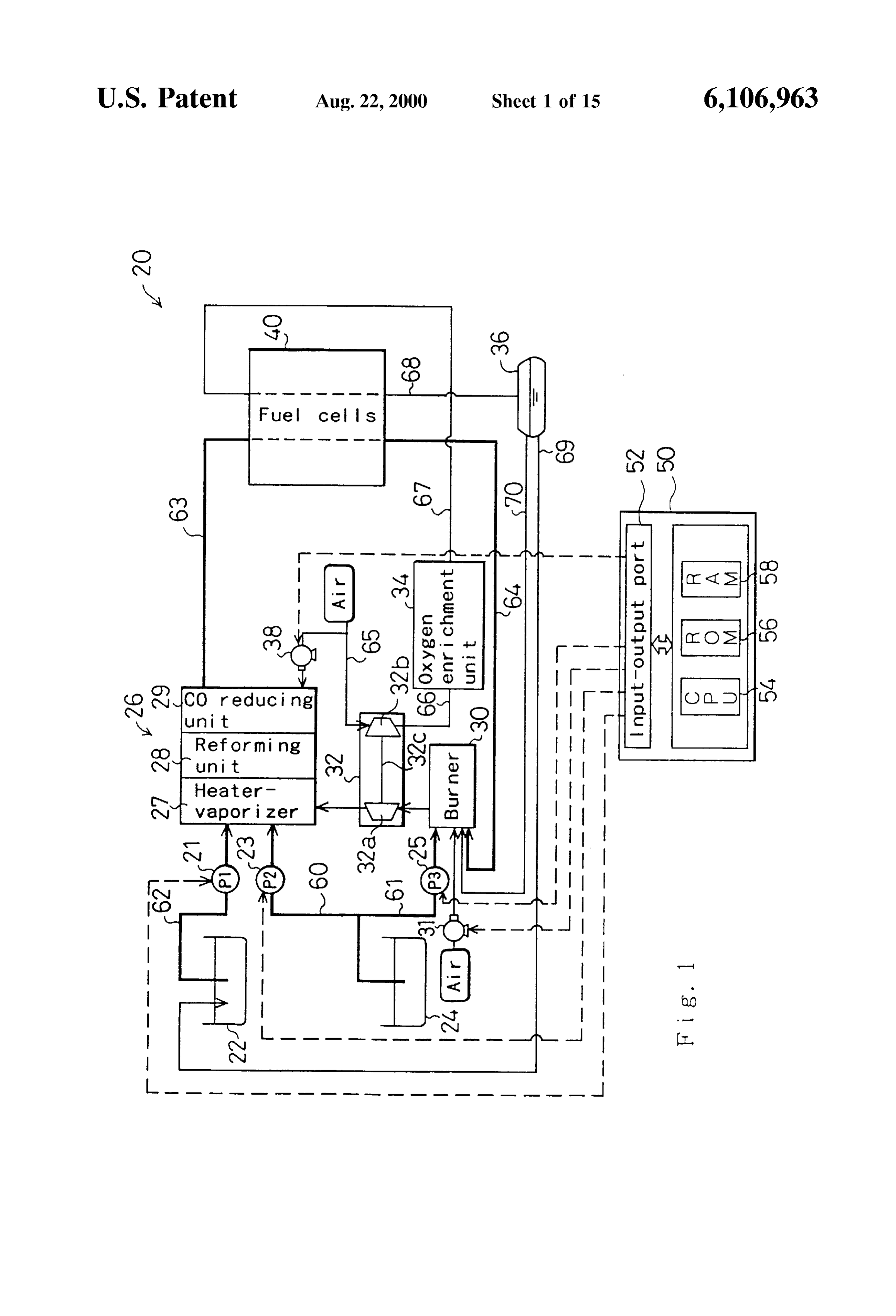
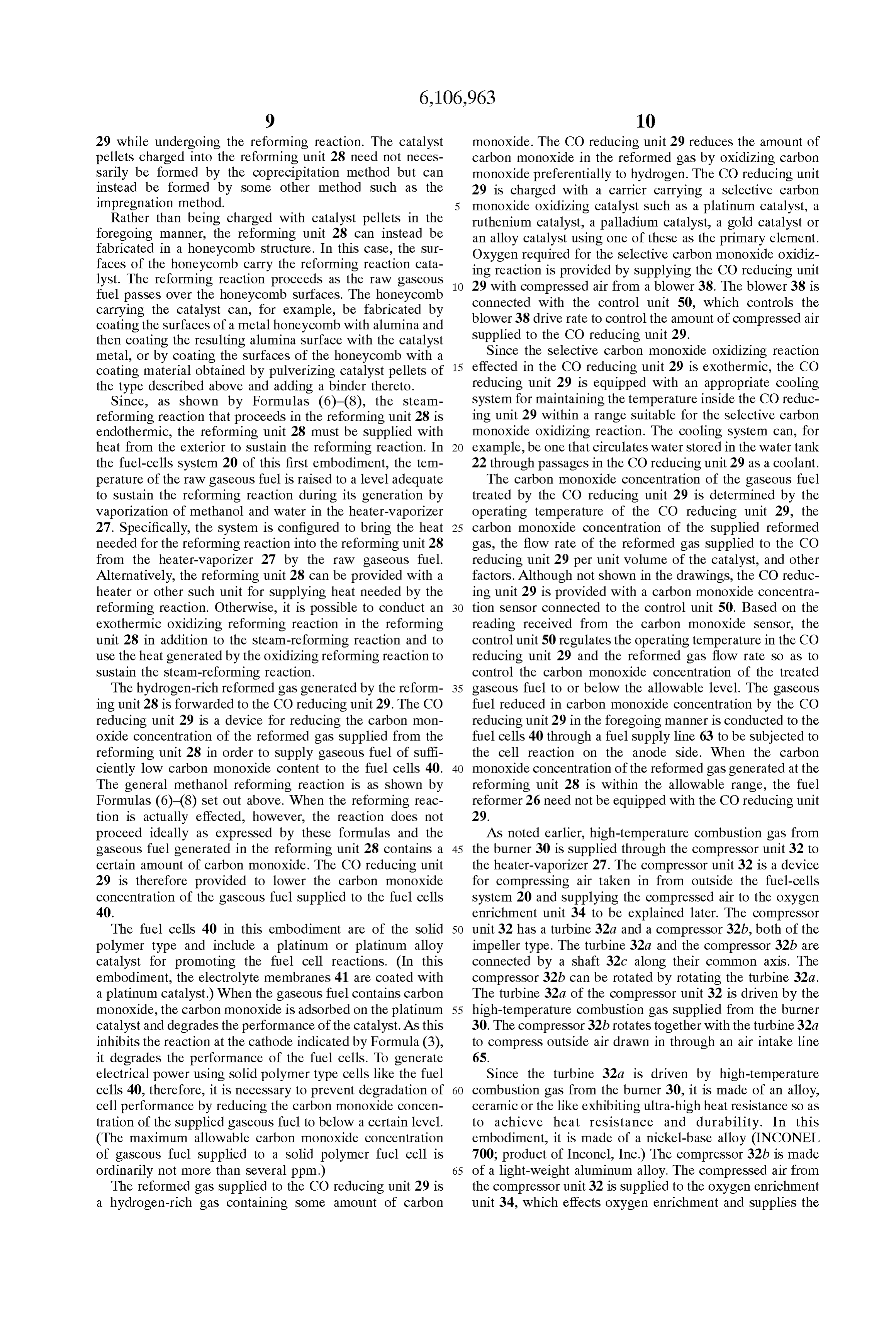
cells that Supply electric power to the motor for driving the magnetic field type. The overall structure of the fuel-cells vehicle are Supplied with oxidizing gas enriched in oxygen system by utilizing the high magnetic Susceptibility of oxygen explained20first. according to the first embodiment will be Following this, the magnetic oxygen enrich molecules in a magnetic field, the electrochemical reactions ment device that constitutes the essential portion of the in the fuel cells are promoted to improve their power invention will be explained.
generating efficiency. Therefore, in addition to the advanta The main components of the fuel-cells system 20 are a geous effects of the fuel-cells System of the invention described in the foregoing, it is further possible to Secure a water tank 22 for Storing water, a methanol tank 24 for greater degree of freedom in the designing of an electric Storing methanol, a burner 30 for generating combustion vehicle owing to the fact that the improved power generating gas, a compressor unit 32 for compressing air, a fuel efficiency of the fuel cells enables the overall size of the 25 reformer 26 for reforming raw fuel (methanol) to generate hydrogen-rich fuel gas, a Stack of fuel cells 40 for producing fuel-cells System to be reduced. electromotive force by electrochemical reactions, an oxygen BRIEF DESCRIPTION OF THE DRAWINGS enrichment unit 34 constituted as a magnetic oxygen enrich ment device, and a control unit 50 consisting of a computer.
FIG. 1 is a block diagram Schematically illustrating the These components of the fuel-cells system 20 will be structure of a fuel-cells system 20 that is a preferred embodi explained in order.
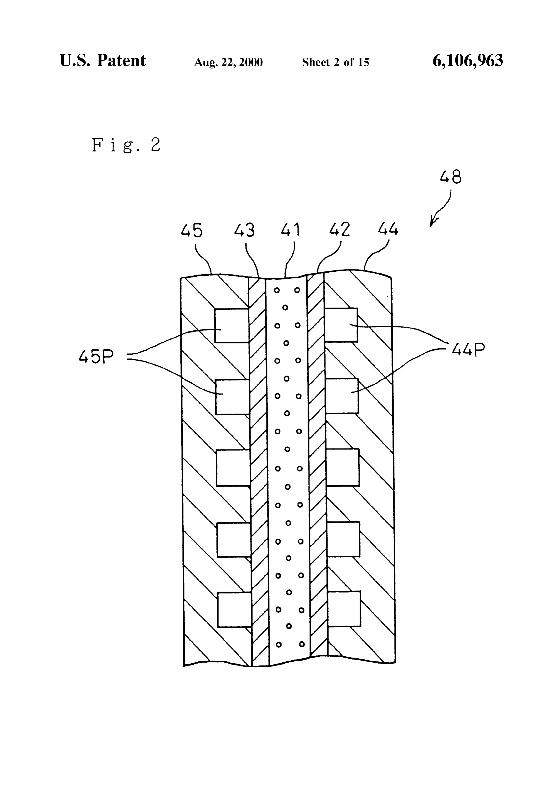
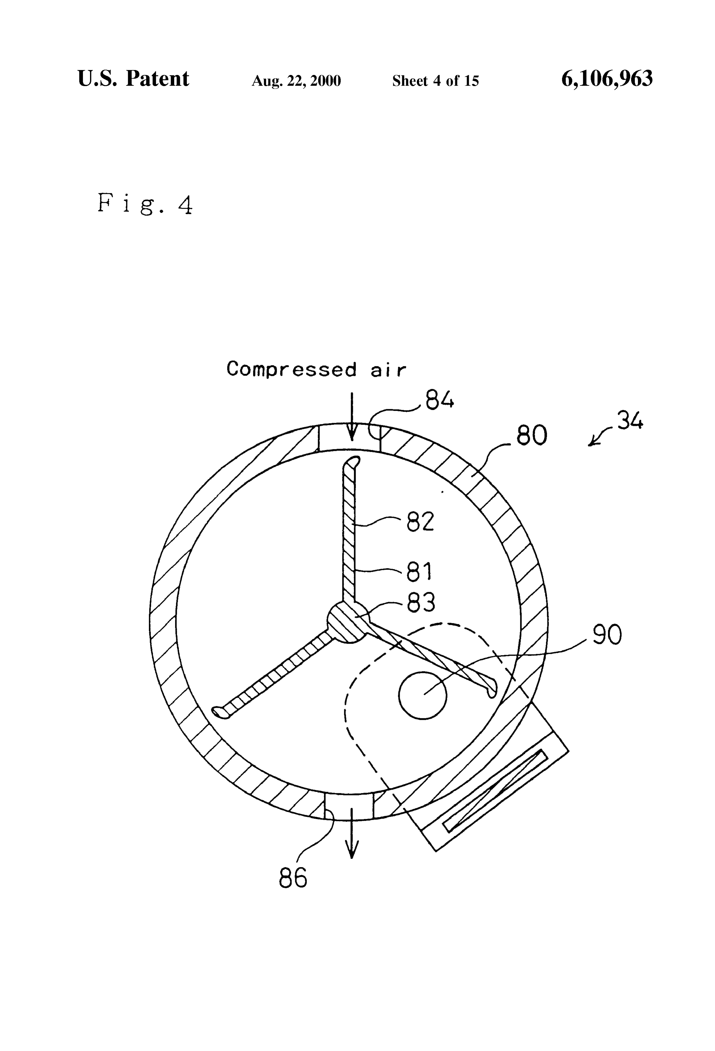
ment of the invention; The stack of fuel cells 40 consists of stacked unit cells 48 FIG. 2 is a Sectional view Schematically illustrating the (FIG. 2) of the Solid polymer type. The formulas below show structure of a unit cell 48 of a stack of fuel cells 40; the electrochemical reactions that occur in the fuel cells 40. FIG. 3 is a sectional view illustrating the structure of an 35 Formula (3) represents the reaction on the anode side and oxygen enrichment unit 34; Formula (4) the reaction on the cathode side. The reaction FIG. 4 is a sectional view of the oxygen enrichment unit occurring in each fuel cell as a whole is shown by Formula 34 taken along section A-A in FIG. 3; (5).
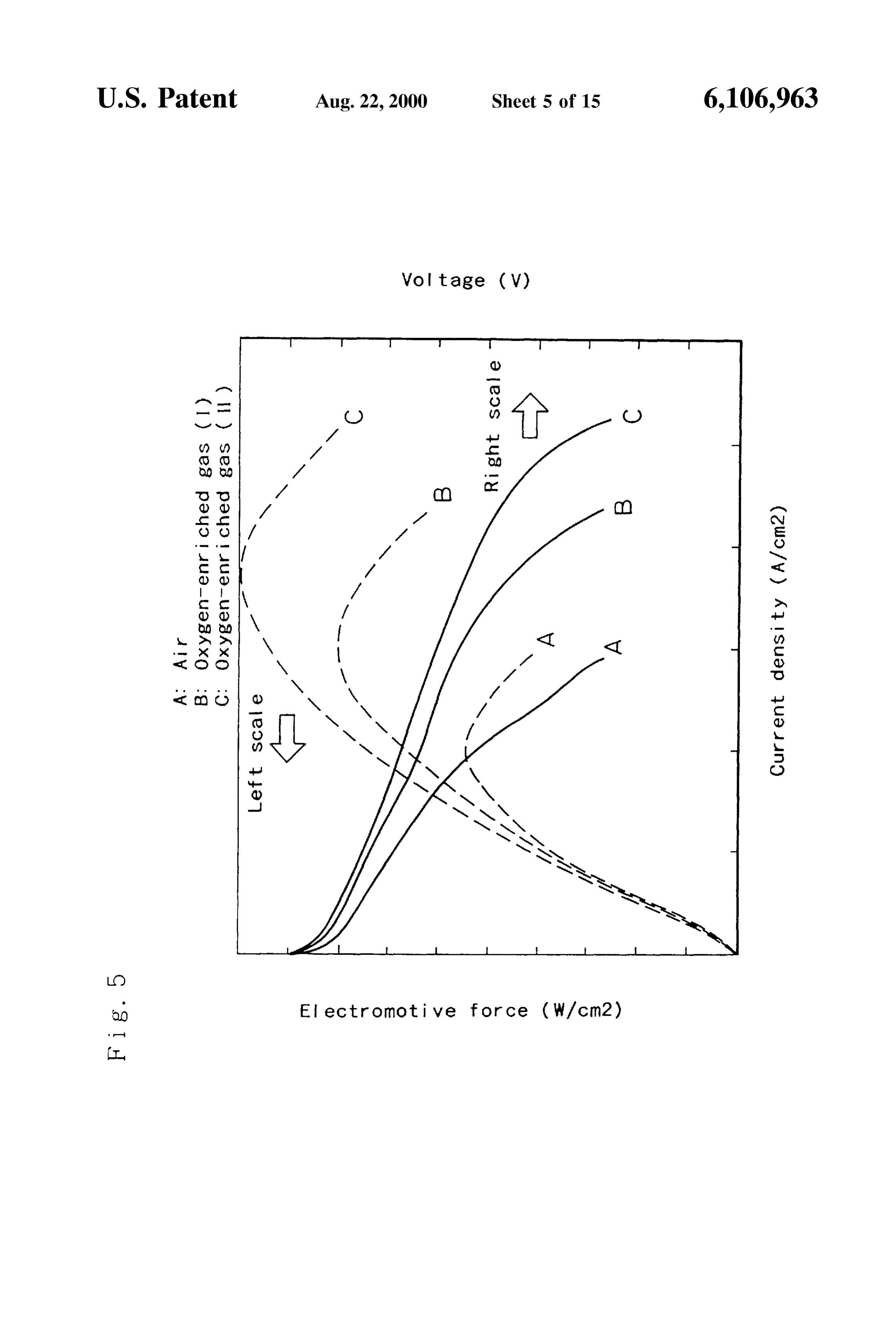
FIG. 5 is a graph showing the results obtained by simu lating how electromotive force and output voltage vary as a 40 function of output current density when oxidizing gases of different oxygen concentration are Supplied to fuel cells,
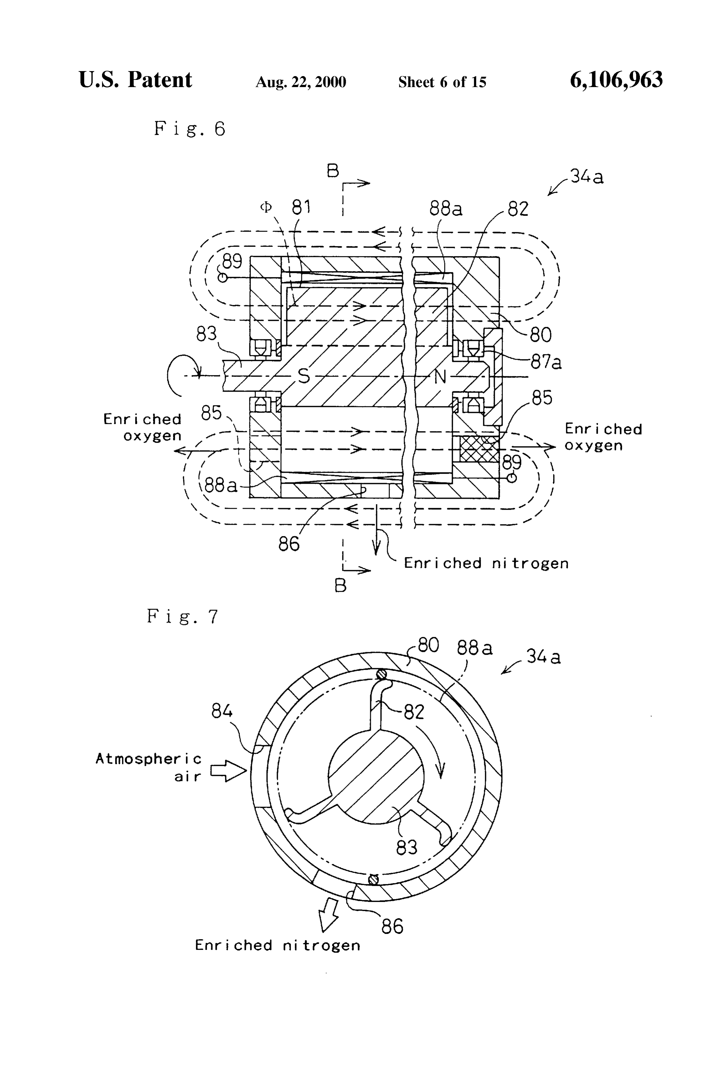
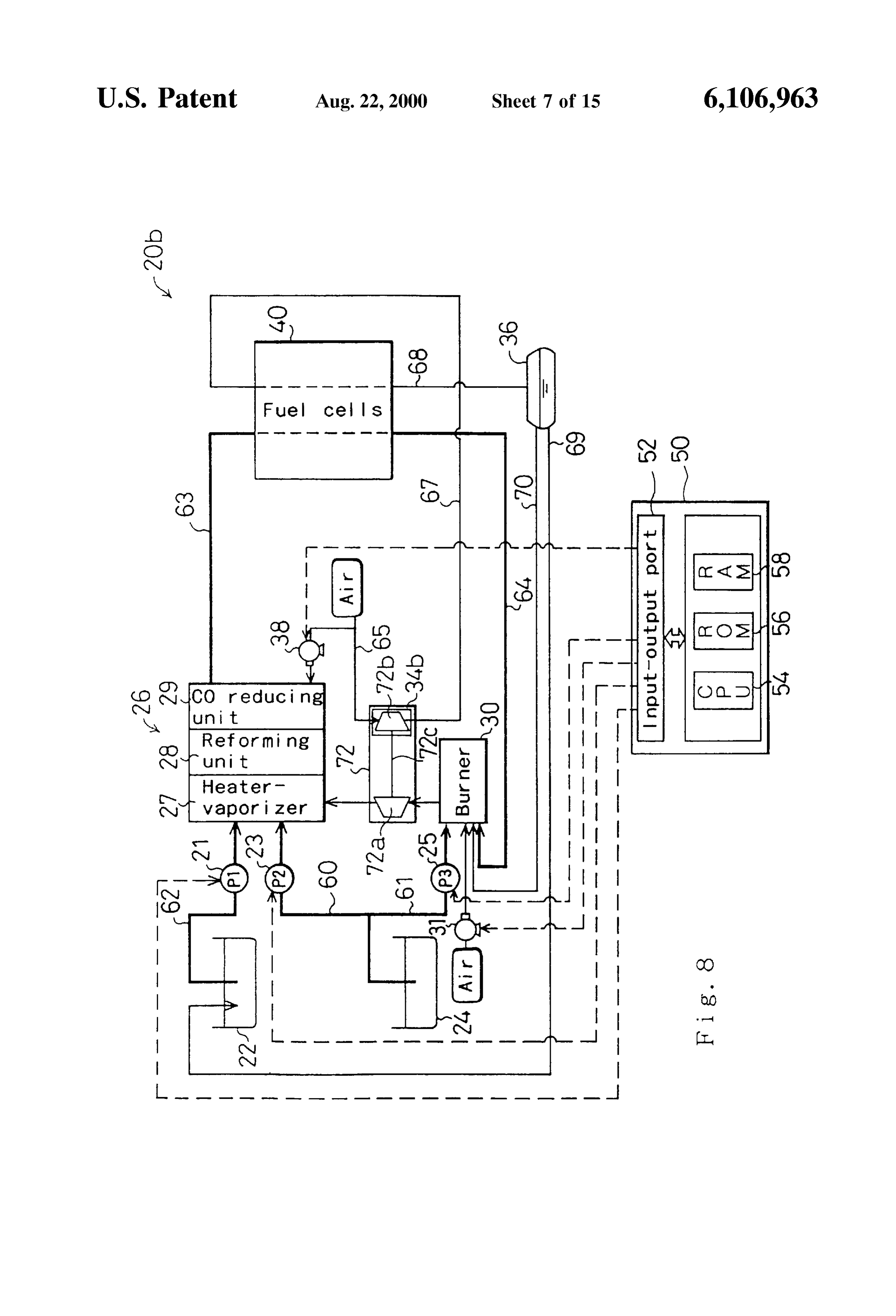
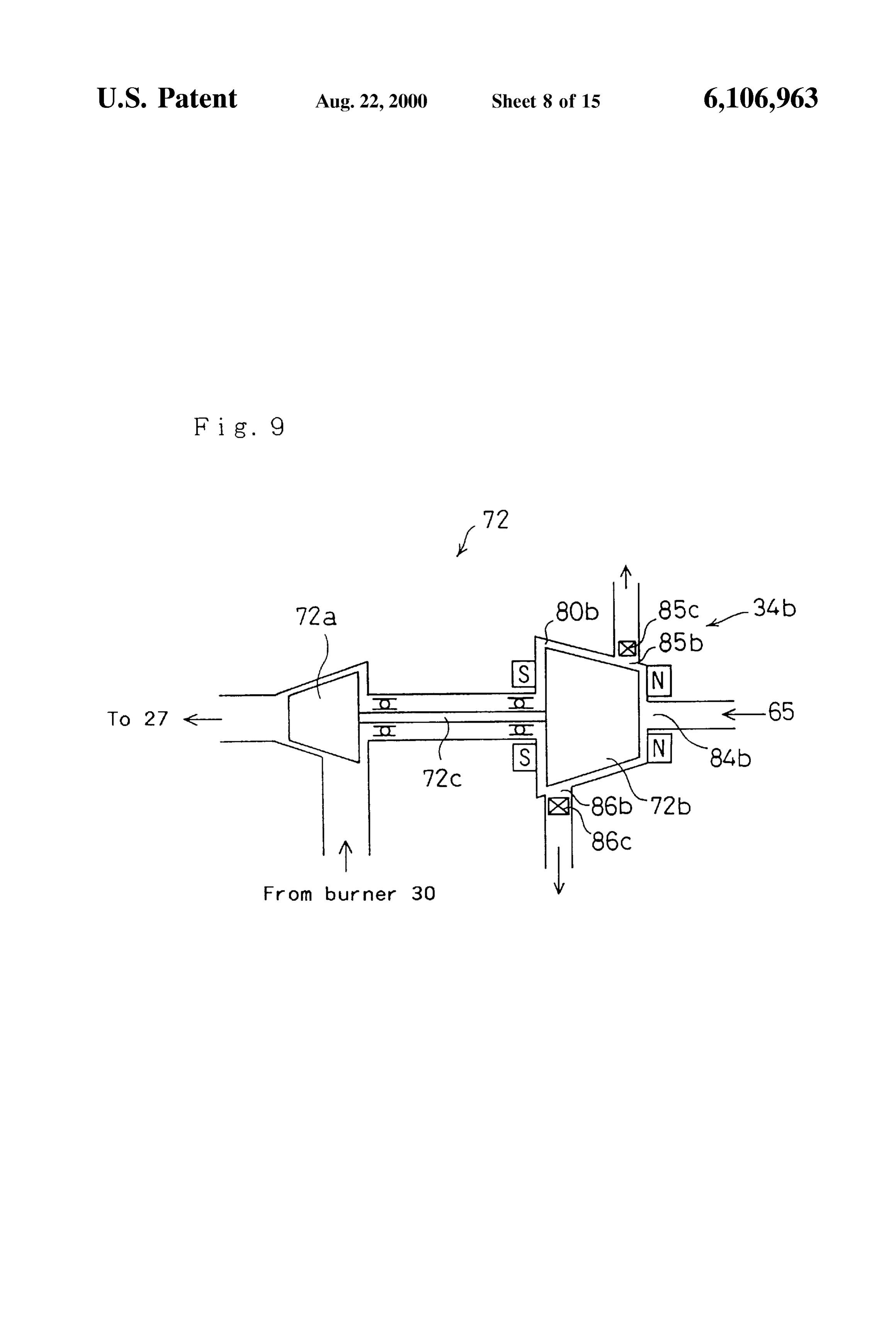
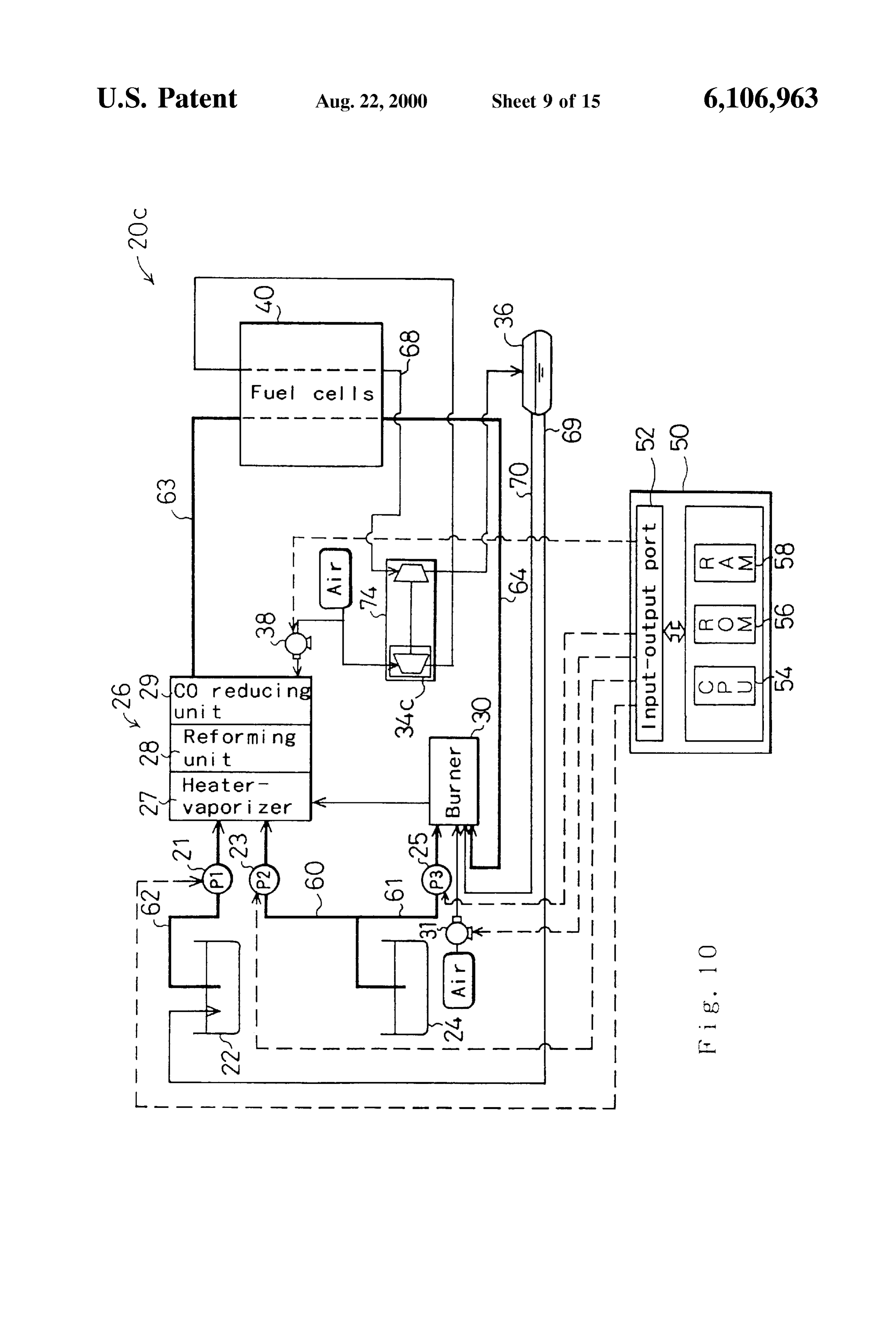
FIG. 6 is a sectional view illustrating the structure of an oxygen enrichment unit 34a, 45 When the fuel cells 40 are supplied with gaseous fuel FIG. 7 is a sectional view of the oxygen enrichment unit containing hydrogen on the cathode Side and with oxidizing 34a taken along section B-B in FIG. 6; gas containing oxygen on the cathode Side, the reactions FIG. 8 is a block diagram schematically illustrating the indicated by Formulas (3)–(5) occur therein to produce an structure of a fuel-cells system 20b, electromotive force. FIG. 2 is a sectional view illustrating FIG. 9 is diagram schematically showing the structure of 50 the structure of a unit cell 48 of the stack of fuel cells 40. The a compressor 72, unit cell 48 is composed of an electrolyte membrane 41, an FIG. 10 is a block diagram schematically illustrating the anode 42, a cathode 43 and separators 44, 45. structure of a fuel-cells system 20c, The anode 42 and the cathode 43 are gas diffusion FIG. 11 is a block diagram schematically illustrating the electrodes that form a sandwich structure with the electro 55 lyte membrane 41 in between. The separators 44, 45 are
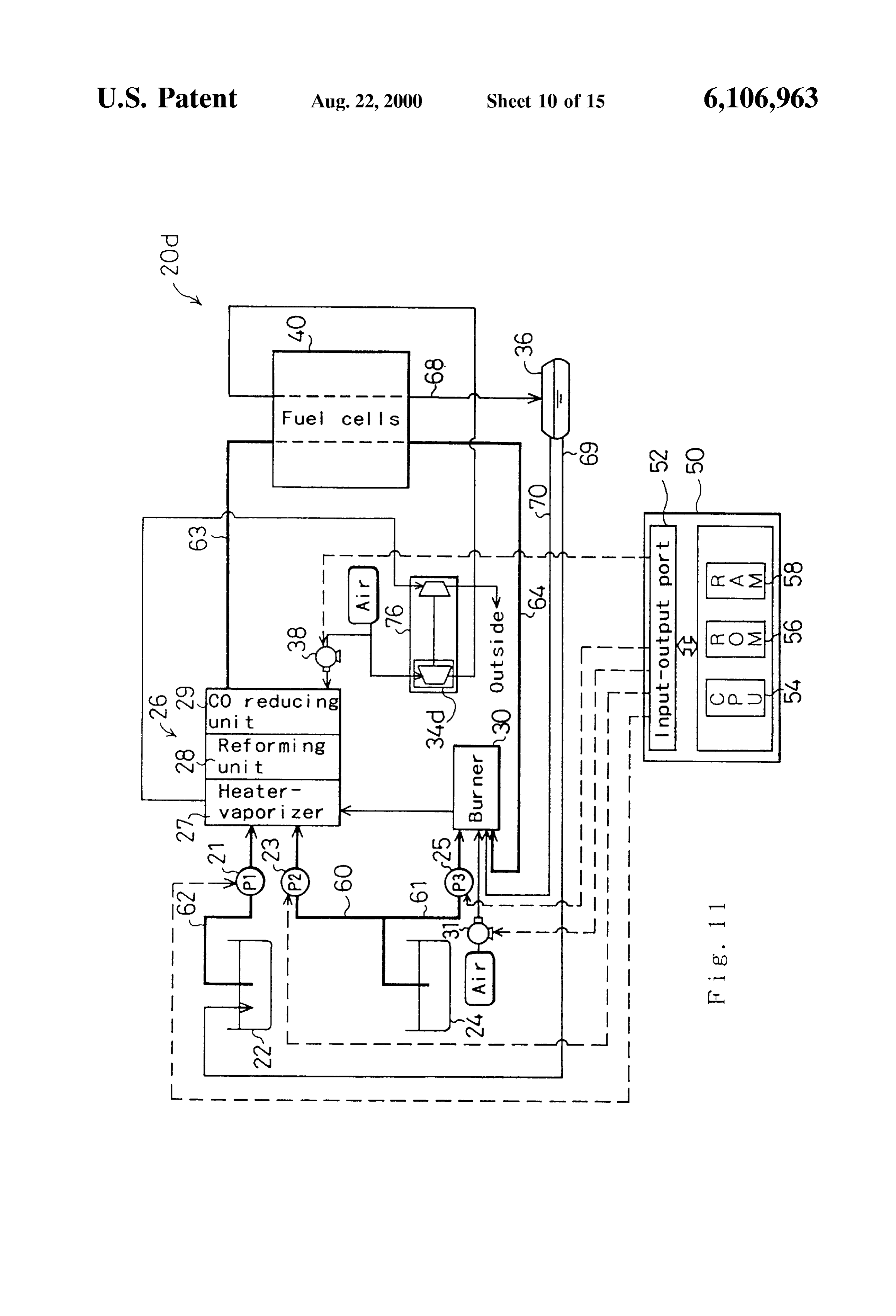
Structure of a fuel-cells System 2d.
disposed on opposite Sides of the Sandwich Structure and are
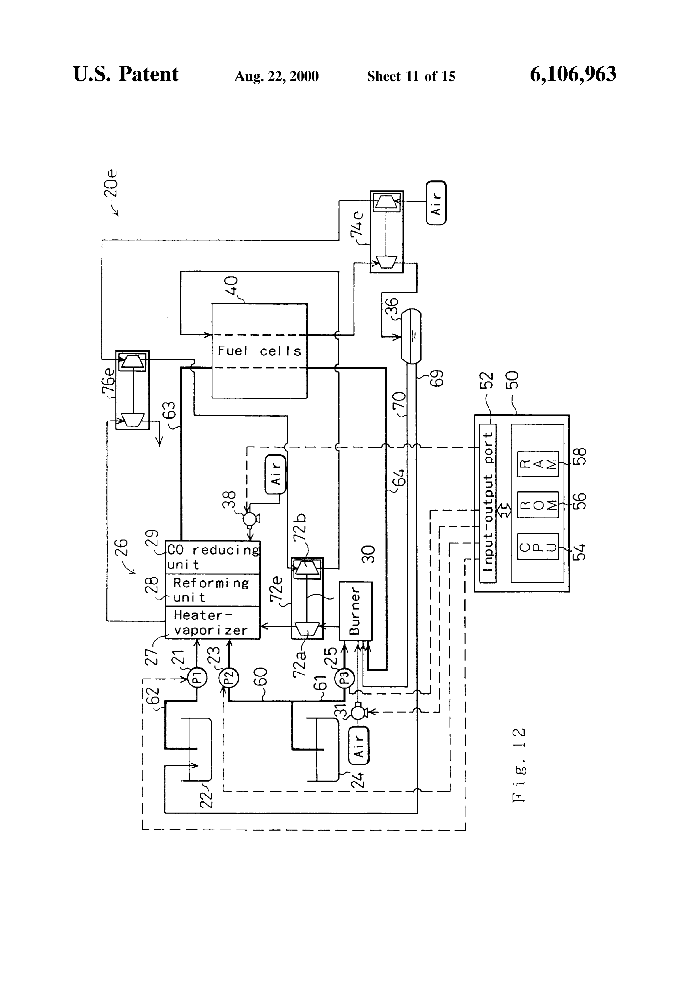
FIG. 12 is a block diagram Schematically illustrating the formed on their sides in contact with the anode 42 and the structure of a fuel-cells system 20e,
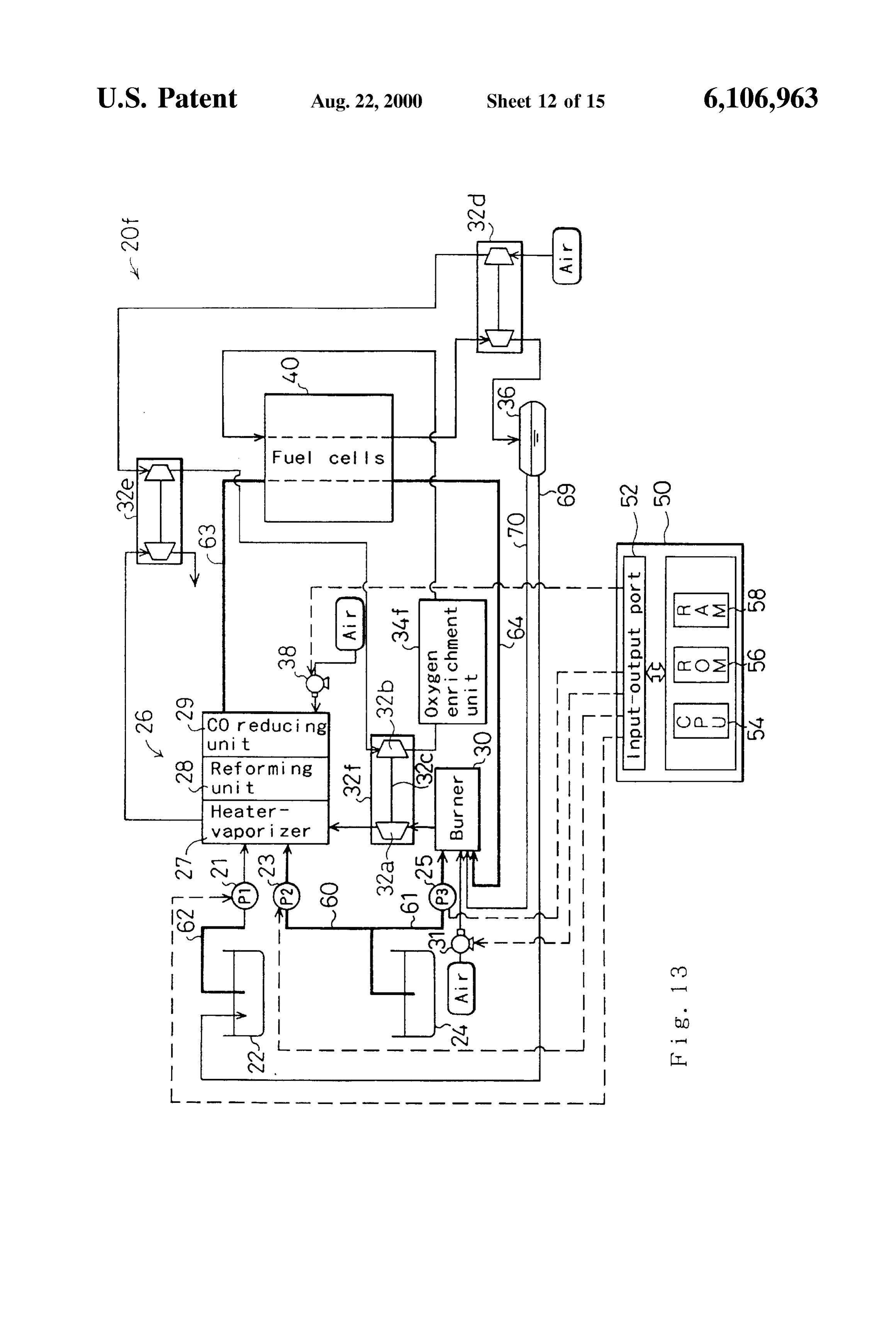
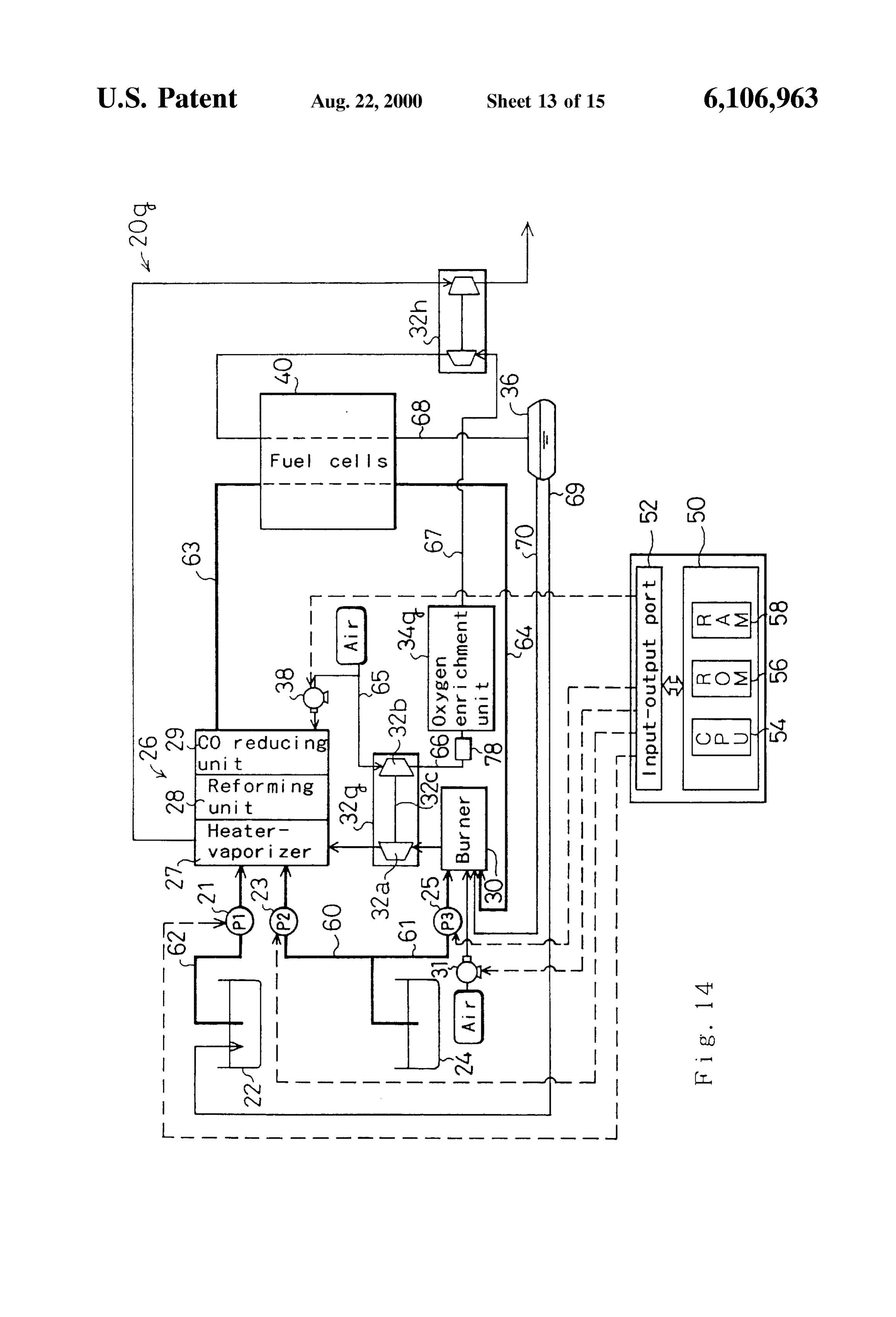
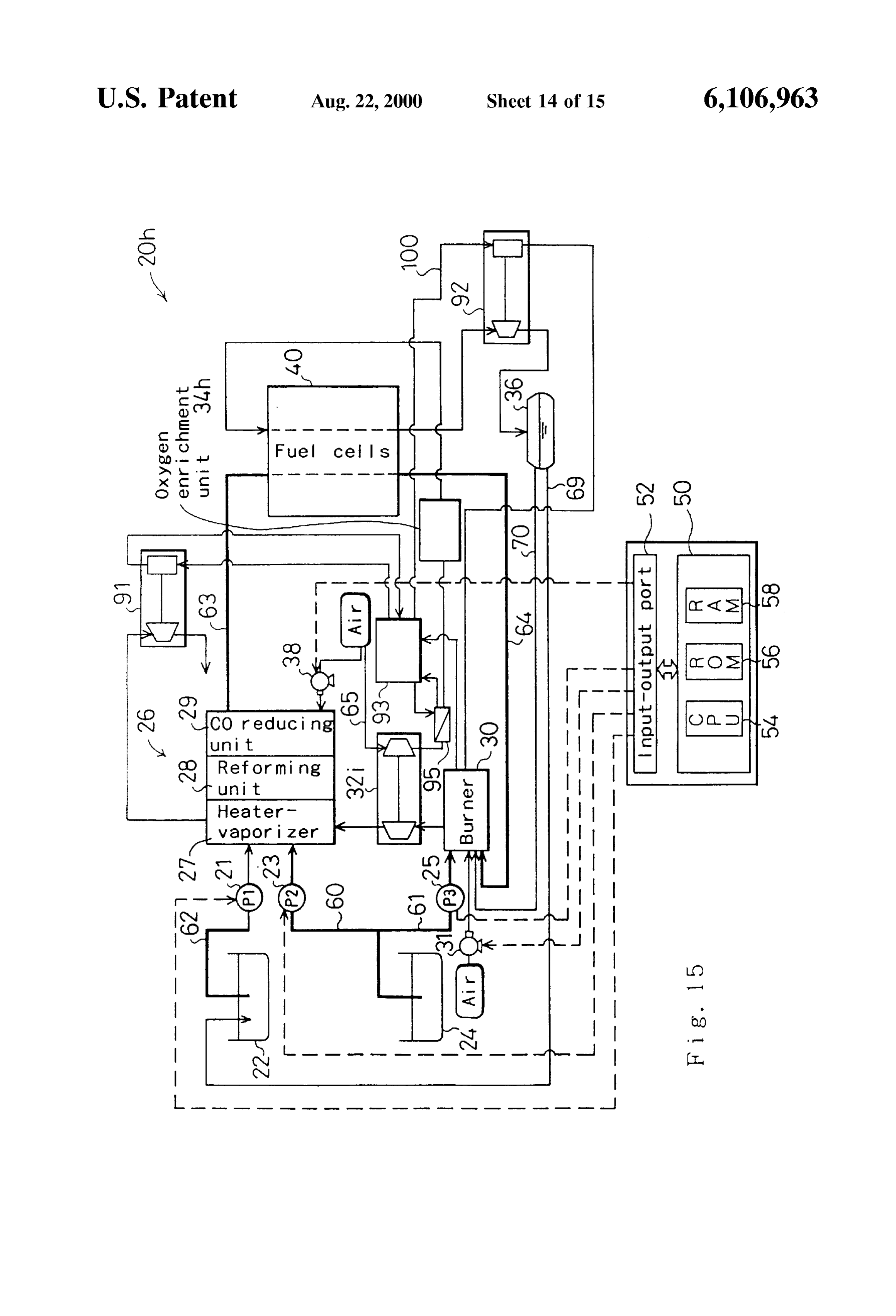
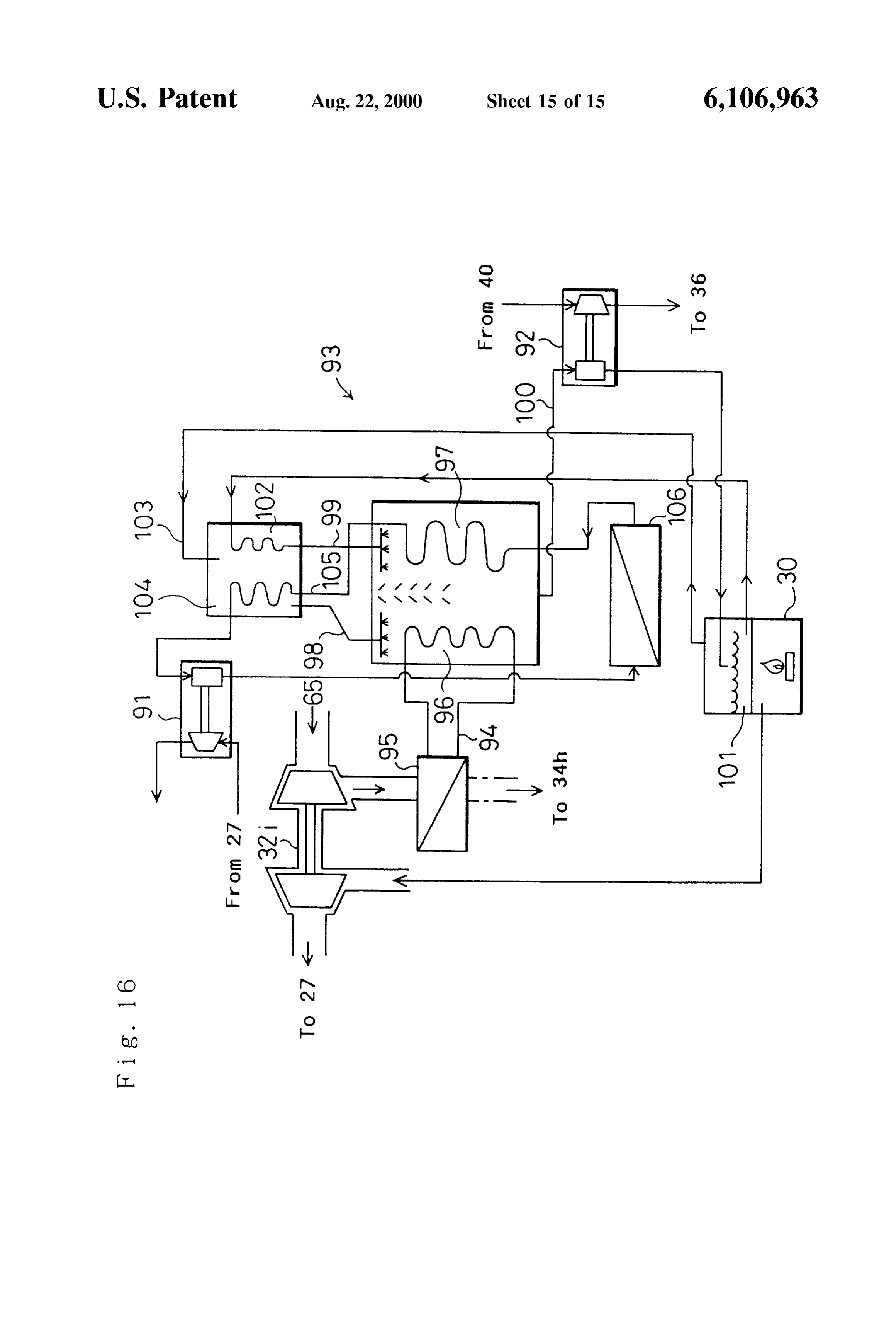
FIG. 13 is a block diagram schematically illustrating the oxidizing43gas.
cathode with channels for passage of gaseous fuel and
Specifically, gaseous fuel channels 44P are structure of a fuel-cells system 20f 60 formed between the anode 42 and the separator 44, and FIG. 14 is a block diagram schematically illustrating the oxidizing gas channels 45P are formed between the cathode structure of a fuel-cells system 20g, 43 and the separator 45. Channels are shown to be formed FIG. 15 is a block diagram schematically illustrating the on only one side of each of the separators 44 and 45 in FIG. structure of a fuel-cells system 20h; and 2. In the actual Structure, channel-forming ribs are formed FIG. 16 is a block diagram schematically illustrating the 65 on both sides of the separators. The ribs on one side of each detailed structure of the portion of the structure of the Separator abut on an anode 42 of one unit cell to form fuel-cells System 20h related to compressed air cooling. gaseous fuel channels 44P while those on the other abut on
Page 20
the cathode 43 of an adjacent unit cell to form oxidizing gas bustion heat from the burner 30 is supplied through the channels 45.P. Each of the separators 44, 45 thus serves to compressor unit 32 to the heater-vaporizer 27 of the fuel form gas channels between itself and the gas diffusion reformer 26. The combustion heat is conducted to a heat electrodes on its opposite Sides and to Separate the gaseous eXchanger in the heater-Vaporizer 27 and heats and vapor fuel flow of one unit cell from the oxidizing gas flow of a 5 izes the methanol and water Supplied to the heater-vaporizer neighboring unit cell. The two separators at the opposite 27.
ends of the stack of unit cells 48 can be left flat on the The methanol used as the raw fuel is fed from the outside and be formed with ribs only on Side making contact methanol tank 24 to the fuel reformer 26 through a methanol with a gas diffusion electrode. line 60 equipped with a second pump 23. The amount of The electrolyte membrane 41 is a proton-conductive methanol Supplied to the fuel reformer 26 can be regulated. ion-exchange membrane composed of a Solid polymer Specifically, the Second pump 23 is connected to the control material, Such as a fluororesin, and exhibits good electrical unit 50 and is controlled by a signal output by the control conductivity when wet. NAFION film (perfluorosulfonic unit 50 to regulate the amount of methanol supplied to the acid polymer, a product of E.I. Du Pont de Nemours & Co., fuel reformer 26.
Inc.) is used in this first embodiment. A coat of platinum or 15 Water is fed from the water tank 22 to the fuel reformer an alloy of platinum and other metal is applied to the Surface 26 through a water line 62 equipped with a first pump 21. of the electrolyte membrane 41 as a catalyst. The coating The amount of water supplied to the fuel reformer 26 can be with the catalyst can be done by the method of preparing a regulated. Specifically, like the Second pump 23, the first carbon powder carrying catalyst (platinum or platinum pump 21 is also connected to the control unit 50 and is alloy), dispersing the carbon powder carrying the catalyst in controlled by a signal output by the control unit 50 to an appropriate organic Solvent, adding an appropriate regulate the amount of water Supplied to the fuel reformer amount of an electrolyte solution (e.g., NAFION solution; 26. The methanol line 60 and the water line 62 are both product of Aldrich Chemical Company, Inc.) to the disper connected to the heater-vaporizer 27 of the fuel reformer 26. Sion to form a paste, and coating the electrolyte membrane The regulated amount of methanol Supplied by the Second 41 with the paste by Screen printing. Good results can also 25 pump 23 and the regulated amount of water Supplied by the be obtained by forming the paste containing the carbon first pump 21 are mixed in the heater-vaporizer 27 and the powder that carries the catalyst into a film-like sheet and resulting methanol-mixture of prescribed mixing ratio is pressing the Sheet onto the electrolyte membrane 41. heated and vaporized. The vaporized methanol and water The anode 42 and the cathode 43 are made of carbon cloth constitute a raw gaseous fuel that is forwarded to the woven from carbon fiber thread. (The invention is not reforming unit 28 and Subjected to a Steam-reforming reac limited to the use of the carbon cloth employed in this first tion. The mixing ratio of methanol and water in the heater embodiment, however, and the anode 42 and the cathode 43 Vaporizer 27 is set to a value that enables the Steam can instead be formed of carbon paper or carbon felt made reforming reaction to proceed thoroughly in the reforming of carbon fiber.) unit 28 and causes the reformed gas to contain a Sufficient The Separators 44, 45 are made of a gas-impermeable 35 amount of Steam to be usable as gaseous fuel for Supply to conductive material Such as dense carbon obtained by com the fuel cells 40. A Steam-reforming reaction expressed by pressing carbon to a gas-impermeable State. The Separators the following formulas occurs in the reforming unit 28. 44, 45 are provided on both sides with multiple parallel ribs,
So that, as explained earlier, the Side of each in contact with CHOH->CO+2H-90.0(kJ/mol) (6) an anode 42 forms gaseous fuel channels 44P and the other 40 (7) Side in contact with the cathode 43 of an adjacent unit cell forms oxidizing gas channels 45P. The ribs on one side of a (8) Separator do not have to be parallel to those on the other side and it is instead possible to form the ribs on opposite sides The methanol decomposing reaction expressed by For to interSect at a prescribed angle Such as 90 degrees. The 45 mula (6) and the carbon monoxide reforming reaction grooves (channels) between the ribs do not necessarily have expressed by Formula (7) proceed simultaneously so that the to run in parallel. Any configuration is possible insofar as the reaction of Formula (8) occurs as the overall methanol formed channels can Supply the gaseous fuel and the oxi Steam-reforming reaction. Thus the reforming unit 28 of the dizing gas to the respective gas diffusion electrodes. fuel reformer 26 is Supplied with raw gaseous fuel consisting The unit cell 48 of the structure explained in the foregoing 50 of methanol and water heated and vaporized by the heater is the basic structural unit of the stack of fuel cells 40. The Vaporizer 27 and generates hydrogen-rich reformed gas by stack of fuel cells 40 is assembled by stacking multiple unit the reaction of Formula (8).
cells 48, i.e., multiple sets (100 in this first embodiment) The reforming unit 28 is charged with pellets formed of each composed of a separator 44, an anode 42, an electrolyte a Cu-Zn catalyst, Cu and Zn being metals that catalyze the membrane 41, a cathode 43 and a separator 45 overlaid in 55 reforming reaction. The reforming unit 28 is Supplied with the order mentioned. The Stack is completed by fitting the aforesaid raw gaseous fuel raised to a Sufficiently high current collector plates formed of dense carbon, copper or temperature and the reforming reaction proceeds therein to the like on the opposite ends. generate hydrogen-rich reformed gas. The pellets formed of The components of the fuel-cells system 20 other than the Cu-Zn catalyst are obtained by preparing the catalyst metal fuel cells 40, and their interconnection, will now be 60 by coprecipitation of copper and Zinc oxide, adding a binder explained. The fuel reformer 26 is composed of a heater Such as alumina to the catalyst metal, and extrusion molding vaporizer 27, a reforming unit 28 and a CO reducing unit 29. the result to form 3-7 mm pellets. This embodiment uses The heater-Vaporizer 27 vaporizes methanol and water Sup pellets measuring about 3x3x3 mm. The pellets consisting plied from the methanol tank 24 and the water tank 22. The of Cu-Zn catalyst are uniformly charged into the reforming Vaporized methanol and water are forwarded from the 65 unit 28. The raw gaseous fuel introduced into the reforming heater-vaporizer 27 to the reforming unit 28 where a steam unit 28 comes in contact with the catalyst metal on the pellet reforming reaction occurs. AS explained further later, com Surfaces and passes toward the Side of the CO reducing unit
Page 21
29 while undergoing the reforming reaction. The catalyst monoxide. The CO reducing unit 29 reduces the amount of pellets charged into the reforming unit 28 need not neces carbon monoxide in the reformed gas by oxidizing carbon Sarily be formed by the coprecipitation method but can monoxide preferentially to hydrogen. The CO reducing unit instead be formed by some other method such as the 29 is charged with a carrier carrying a Selective carbon impregnation method. monoxide oxidizing catalyst Such as a platinum catalyst, a Rather than being charged with catalyst pellets in the ruthenium catalyst, a palladium catalyst, a gold catalyst or foregoing manner, the reforming unit 28 can instead be an alloy catalyst using one of these as the primary element. fabricated in a honeycomb Structure. In this case, the Sur Oxygen required for the Selective carbon monoxide oxidiz faces of the honeycomb carry the reforming reaction cata ing reaction is provided by Supplying the CO reducing unit lyst. The reforming reaction proceeds as the raw gaseous 29 with compressed air from a blower 38. The blower 38 is fuel passes over the honeycomb Surfaces. The honeycomb connected with the control unit 50, which controls the carrying the catalyst can, for example, be fabricated by blower 38 drive rate to control the amount of compressed air coating the Surfaces of a metal honeycomb with alumina and supplied to the CO reducing unit 29. then coating the resulting alumina Surface with the catalyst metal, or by coating the Surfaces of the honeycomb with a 15 Since the Selective carbon monoxide oxidizing reaction coating material obtained by pulverizing catalyst pellets of effected in the CO reducing unit 29 is exothermic, the CO the type described above and adding a binder thereto. reducing unit 29 is equipped with an appropriate cooling Since, as shown by Formulas (6)–(8), the steam System for maintaining the temperature inside the CO reduc reforming reaction that proceeds in the reforming unit 28 is ing unit 29 within a range suitable for the selective carbon endothermic, the reforming unit 28 must be supplied with monoxide oxidizing reaction. The cooling System can, for heat from the exterior to Sustain the reforming reaction. In example, be one that circulates water Stored in the water tank the fuel-cells system 20 of this first embodiment, the tem 22 through passages in the CO reducing unit 29 as a coolant. perature of the raw gaseous fuel is raised to a level adequate The carbon monoxide concentration of the gaseous fuel to Sustain the reforming reaction during its generation by treated by the CO reducing unit 29 is determined by the Vaporization of methanol and water in the heater-Vaporizer operating temperature of the CO reducing unit 29, the 27. Specifically, the System is configured to bring the heat 25 carbon monoxide concentration of the Supplied reformed needed for the reforming reaction into the reforming unit 28 gas, the flow rate of the reformed gas Supplied to the CO from the heater-vaporizer 27 by the raw gaseous fuel. reducing unit 29 per unit volume of the catalyst, and other Alternatively, the reforming unit 28 can be provided with a factors. Although not shown in the drawings, the CO reduc heater or other Such unit for Supplying heat needed by the ing unit 29 is provided with a carbon monoxide concentra reforming reaction. Otherwise, it is possible to conduct an tion sensor connected to the control unit 50. Based on the exothermic oxidizing reforming reaction in the reforming reading received from the carbon monoxide Sensor, the unit 28 in addition to the Steam-reforming reaction and to control unit 50 regulates the operating temperature in the CO use the heat generated by the oxidizing reforming reaction to reducing unit 29 and the reformed gas flow rate So as to Sustain the Steam-reforming reaction. control the carbon monoxide concentration of the treated The hydrogen-rich reformed gas generated by the reform 35 gaseous fuel to or below the allowable level. The gaseous ing unit 28 is forwarded to the CO reducing unit 29. The CO fuel reduced in carbon monoxide concentration by the CO reducing unit 29 is a device for reducing the carbon mon reducing unit 29 in the foregoing manner is conducted to the oxide concentration of the reformed gas Supplied from the fuel cells 40 through a fuel Supply line 63 to be subjected to reforming unit 28 in order to Supply gaseous fuel of Suffi the cell reaction on the anode side. When the carbon ciently low carbon monoxide content to the fuel cells 40. 40 monoxide concentration of the reformed gas generated at the The general methanol reforming reaction is as shown by reforming unit 28 is within the allowable range, the fuel Formulas (6)–(8) set out above. When the reforming reac reformer 26 need not be equipped with the CO reducing unit tion is actually effected, however, the reaction does not 29.
proceed ideally as expressed by these formulas and the AS noted earlier, high-temperature combustion gas from gaseous fuel generated in the reforming unit 28 contains a 45 the burner 30 is supplied through the compressor unit 32 to certain amount of carbon monoxide. The CO reducing unit the heater-vaporizer 27. The compressor unit 32 is a device 29 is therefore provided to lower the carbon monoxide for compressing air taken in from outside the fuel-cells concentration of the gaseous fuel Supplied to the fuel cells System 20 and Supplying the compressed air to the oxygen 40. enrichment unit 34 to be explained later. The compressor The fuel cells 40 in this embodiment are of the Solid 50 unit 32 has a turbine 32a and a compressor 32b, both of the polymer type and include a platinum or platinum alloy impeller type. The turbine 32a and the compressor 32b are catalyst for promoting the fuel cell reactions. (In this connected by a shaft 32c along their common axis. The embodiment, the electrolyte membranes 41 are coated with compressor 32b can be rotated by rotating the turbine 32a. a platinum catalyst.) When the gaseous fuel contains carbon The turbine 32a of the compressor unit 32 is driven by the monoxide, the carbon monoxide is adsorbed on the platinum 55 high-temperature combustion gas Supplied from the burner catalyst and degrades the performance of the catalyst. AS this 30. The compressor 32b rotates together with the turbine 32a inhibits the reaction at the cathode indicated by Formula (3), to compress outside air drawn in through an air intake line it degrades the performance of the fuel cells. To generate 65.
electrical power using Solid polymer type cells like the fuel Since the turbine 32a is driven by high-temperature cells 40, therefore, it is necessary to prevent degradation of 60 combustion gas from the burner 30, it is made of an alloy, cell performance by reducing the carbon monoxide concen ceramic or the like exhibiting ultra-high heat resistance So as tration of the Supplied gaseous fuel to below a certain level. to achieve heat resistance and durability. In this (The maximum allowable carbon monoxide concentration embodiment, it is made of a nickel-base alloy (INCONEL of gaseous fuel Supplied to a Solid polymer fuel cell is 700; product of Inconel, Inc.) The compressor 32b is made ordinarily not more than Several ppm.) 65 of a light-weight aluminum alloy. The compressed air from The reformed gas supplied to the CO reducing unit 29 is the compressor unit 32 is Supplied to the oxygen enrichment a hydrogen-rich gas containing Some amount of carbon unit 34, which effects oxygen enrichment and Supplies the
Page 22
oxygen-enriched oxidizing gas to the fuel cells 40. (The water recovery vessel 36 is supplied to the water tank 22 Structure of the oxygen enrichment unit 34 is explained in through a water recovery line 69 and then, after being passed detail later.) through the heater-vaporizer 27, is used in the Steam The burner 30 that drives the turbine 32a is supplied with reforming reaction of the raw fuel conducted in reforming fuel for combustion from the cathode side of the fuel cells unit 28. The oxidizing gas removed of the generated water 40 and from the methanol tank 24. Although, the hydrogen in the condensed water recovery vessel 36 contains residual rich gas generated in the fuel reformer 26 by methanol oxygen not used in the cell reaction. It is therefore Supplied reformation is used as the fuel for the electrochemical through an exhaust oxidizing gas line 70 to the burner 30, reactions in the fuel cells 40, not all of the hydrogen supplied which uses it in the combustion reaction. to the fuel cells 40 is consumed. The exhaust gaseous fuel The control unit 50 is a logic circuit configured around a from the fuel cells 40 containing the remaining unconsumed microcomputer. Specifically, it comprises a CPU 54 for hydrogen is discharged through an exhaust gaseous fuel line executing prescribed arithmetic operations and the like in 64 to the burner 30 where the remaining unconsumed accordance with a control program written in advance, a hydrogen is completely burned, thereby enhancing fuel ROM 56 preloaded with the control program, control data utilization efficiency. The burner 30 is supplied with metha 15 and the like necessary for executing various types of arith nol from the methanol tank 24 to make up for the fuel metic processing in the CPU 54, a RAM 58 for temporary Shortfall owing to insufficiency of the exhaust fuel and also reading and writing of various data also necessary for when supply of exhaust fuel cannot be obtained from the various types of arithmetic processing in the CPU 54, and an fuel cells 40 such as at the time of fuel-cells system 20 input-output port 52 for outputting drive Signals to the Startup. A methanol branch line 61 is provided for Supplying pumps, blowers etc. based on the results of the processing by methanol to the burner 30. The methanol branch line 61 the CPU 54.
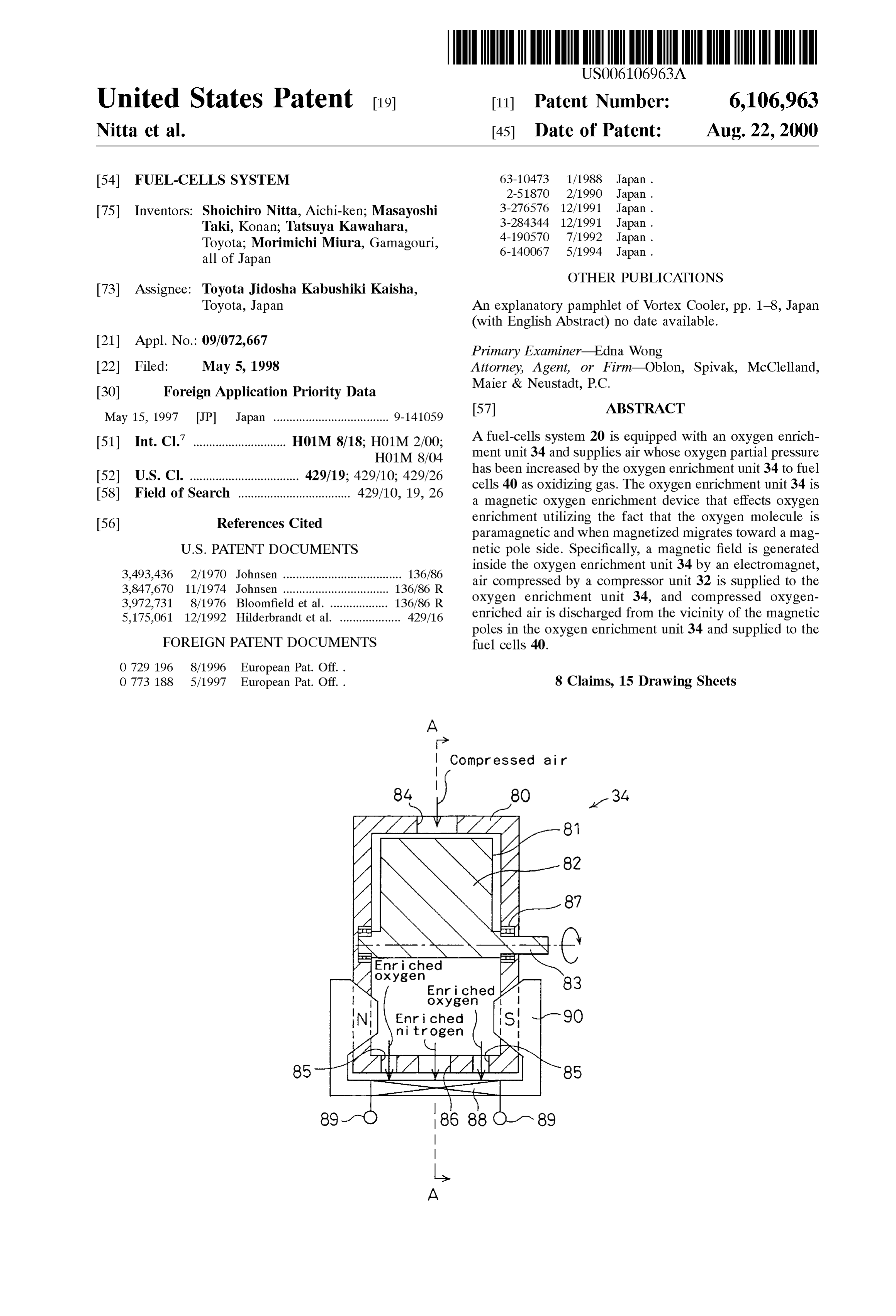
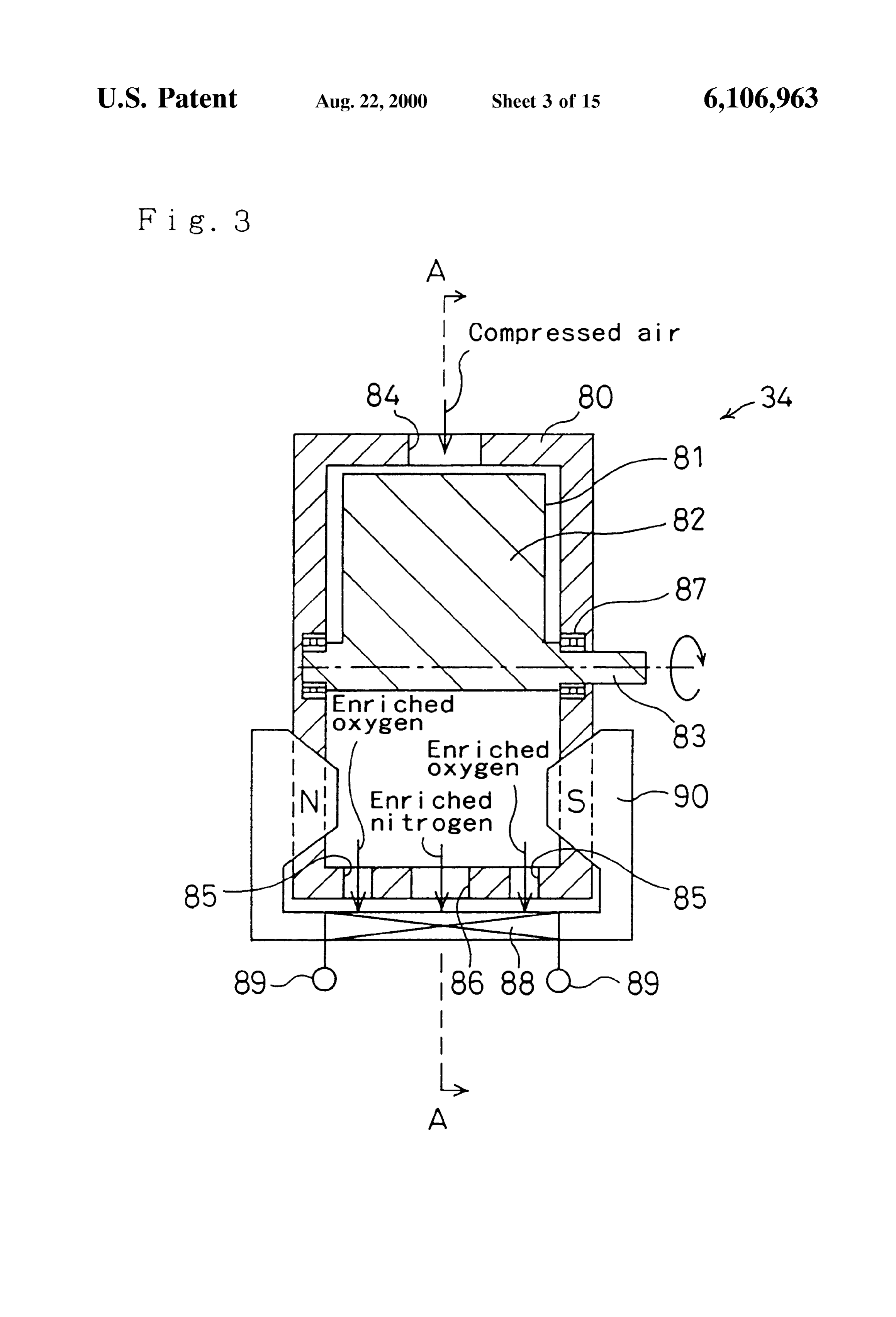
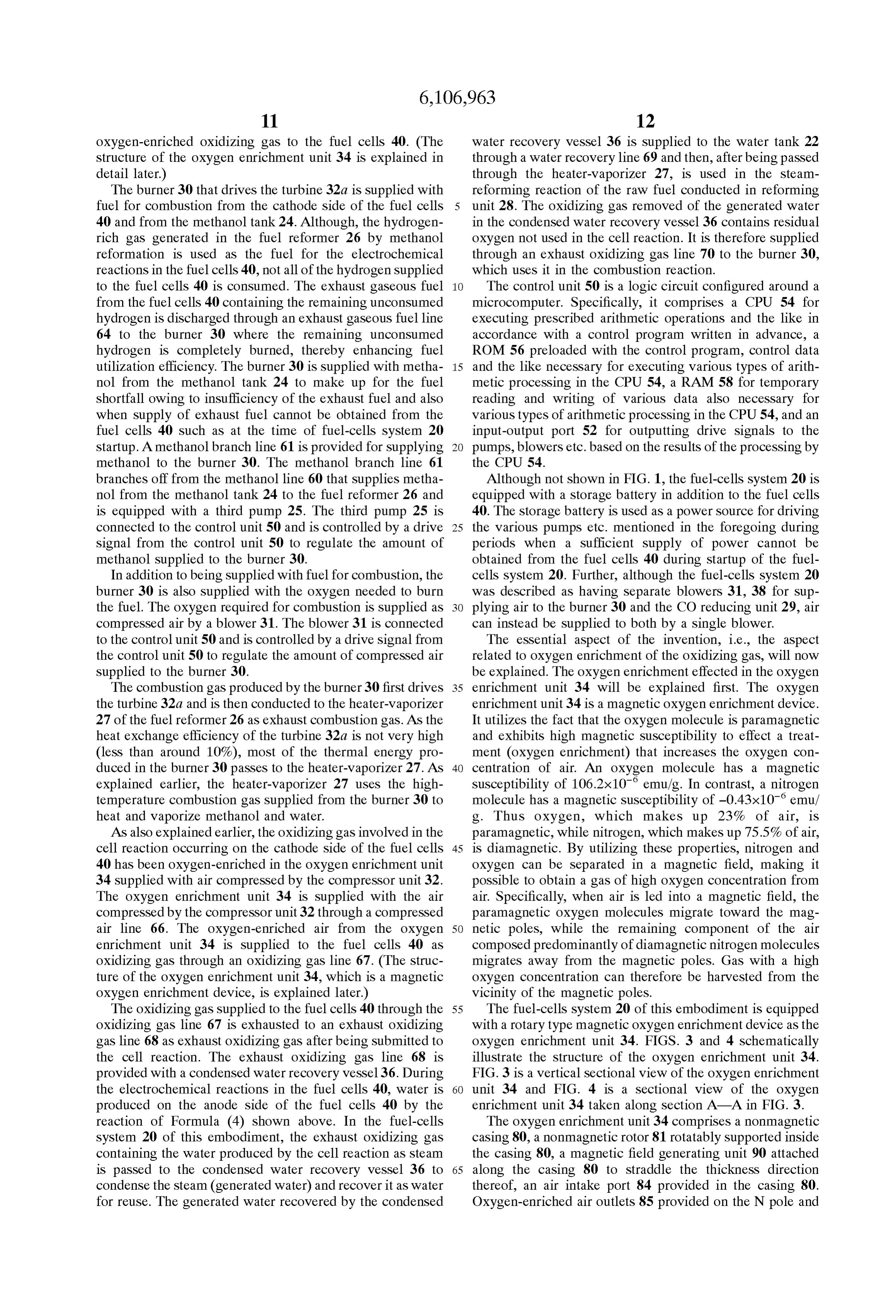
branches off from the methanol line 60 that supplies metha Although not shown in FIG. 1, the fuel-cells system 20 is nol from the methanol tank 24 to the fuel reformer 26 and equipped with a storage battery in addition to the fuel cells is equipped with a third pump 25. The third pump 25 is 40. The Storage battery is used as a power Source for driving connected to the control unit 50 and is controlled by a drive 25 the various pumps etc. mentioned in the foregoing during signal from the control unit 50 to regulate the amount of periods when a Sufficient Supply of power cannot be methanol supplied to the burner 30. obtained from the fuel cells 40 during startup of the fuel In addition to being Supplied with fuel for combustion, the cells system 20. Further, although the fuel-cells system 20 burner 30 is also supplied with the oxygen needed to burn was described as having separate blowers 31, 38 for Sup the fuel. The oxygen required for combustion is Supplied as plying air to the burner 30 and the CO reducing unit 29, air compressed air by a blower 31. The blower 31 is connected can instead be Supplied to both by a single blower. to the control unit 50 and is controlled by a drive signal from The essential aspect of the invention, i.e., the aspect the control unit 50 to regulate the amount of compressed air related to OXygen enrichment of the oxidizing gas, Will now supplied to the burner 30. be explained. The oxygen enrichment effected in the oxygen The combustion gas produced by the burner 30 first drives 35 enrichment unit 34 will be explained first. The oxygen the turbine 32a and is then conducted to the heater-vaporizer enrichment unit 34 is a magnetic oxygen enrichment device. 27 of the fuel reformer 26 as exhaust combustion gas. As the It utilizes the fact that the oxygen molecule is paramagnetic heat eXchange efficiency of the turbine 32a is not very high and exhibits high magnetic Susceptibility to effect a treat (less than around 10%), most of the thermal energy pro ment (oxygen enrichment) that increases the oxygen con duced in the burner 30 passes to the heater-vaporizer 27. As 40 centration of air. An oxygen molecule has a magnetic explained earlier, the heater-vaporizer 27 uses the high susceptibility of 106.2x10 emu/g. In contrast, a nitrogen temperature combustion gas Supplied from the burner 30 to molecule has a magnetic susceptibility of -0.43x10 emu/ heat and vaporize methanol and water. g. Thus oxygen, which makes up 23% of air, is AS also explained earlier, the oxidizing gas involved in the paramagnetic, while nitrogen, which makes up 75.5% of air, cell reaction occurring on the cathode Side of the fuel cells 45 is diamagnetic. By utilizing these properties, nitrogen and 40 has been oxygen-enriched in the oxygen enrichment unit oxygen can be separated in a magnetic field, making it 34 supplied with air compressed by the compressor unit 32. possible to obtain a gas of high oxygen concentration from The oxygen enrichment unit 34 is supplied with the air air. Specifically, when air is led into a magnetic field, the compressed by the compressor unit 32 through a compressed paramagnetic oxygen molecules migrate toward the mag air line 66. The oxygen-enriched air from the oxygen 50 netic poles, while the remaining component of the air enrichment unit 34 is supplied to the fuel cells 40 as composed predominantly of diamagnetic nitrogen molecules oxidizing gas through an oxidizing gas line 67. (The Struc migrates away from the magnetic poles. Gas with a high ture of the oxygen enrichment unit 34, which is a magnetic oxygen concentration can therefore be harvested from the oxygen enrichment device, is explained later.) vicinity of the magnetic poles. The oxidizing gas supplied to the fuel cells 40 through the 55 The fuel-cells system 20 of this embodiment is equipped oxidizing gas line 67 is exhausted to an exhaust oxidizing with a rotary type magnetic oxygen enrichment device as the gas line 68 as exhaust oxidizing gas after being Submitted to oxygen enrichment unit 34. FIGS. 3 and 4 schematically the cell reaction. The exhaust oxidizing gas line 68 is illustrate the Structure of the oxygen enrichment unit 34. provided with a condensed water recovery vessel 36. During FIG. 3 is a vertical sectional view of the oxygen enrichment the electrochemical reactions in the fuel cells 40, water is 60 unit 34 and FIG. 4 is a sectional view of the oxygen produced on the anode side of the fuel cells 40 by the enrichment unit 34 taken along section A-A in FIG. 3. reaction of Formula (4) shown above. In the fuel-cells The oxygen enrichment unit 34 comprises a nonmagnetic System 20 of this embodiment, the exhaust oxidizing gas casing 80, a nonmagnetic rotor 81 rotatably Supported inside containing the water produced by the cell reaction as Steam the casing 80, a magnetic field generating unit 90 attached is passed to the condensed water recovery vessel 36 to 65 along the casing 80 to Straddle the thickness direction condense the Steam (generated water) and recover it as water thereof, an air intake port 84 provided in the casing 80. for reuse. The generated water recovered by the condensed Oxygen-enriched air outlets 85 provided on the N pole and
Page 23
Spole sides near the opposite ends of the casing 80 in the casing 80 in the axial direction. Thus a high oxygen axial direction, and a nitrogen-enriched air outlet 86 pro concentration gas Separation unit is present in a specific area vided in the casing 80 midway between the N pole and the in the vicinity of at least one of the poles N or S, and a low Spole together comprising a varying oxygen-concentration oxygen-concentration gas Separation unit is present in gas separation unit. The casing 80 is formed of a hollow another area farther from the magnetic pole. cylindrical wall and end plates on opposite ends thereof. The Since the oxygen enrichment unit 34 is Supplied with rotor 81 comprises a shaft 83 and multiple vanes 82. The compressed air by the compressor unit 32, the oxidizing gas shaft 83 is supported on the casing 80 by radial ball bearings discharged from the oxygen enrichment unit 34 into the 87 and is rotated by a motor or other such drive unit (not oxidizing gas line 67 is also in a compressed State. The shown). When the shaft 83 is rotated, the vanes 82 rotate cathode side of the fuel cells 40 is therefore supplied with unitarily with the shaft 83 to function as a blower. The oxidizing gas whose oxygen partial pressure has been magnetic field generating unit 90 generates a magnetic field ment. greatly increased by both compression and oxygen enrich whose magnetic lines of force run in the axial direction of In the first embodiment of the fuel-cells system 20 con the shaft 83 in the inner space of the casing 80. The air intake Stituted in the foregoing manner, Since the fuel cells 40 are port 84 is connected to the compressed air line 66 referred 15 Supplied with oxidizing gas that has been oxygen-enriched to earlier to enable intake of air compressed by the com by the Oxygen enrichment unit 34, the power generating pressor unit 32. The oxygen-enriched air outlets 85 are efficiency of the fuel cells 40 is enhanced. This is because connected to the oxidizing gas line 67 to enable Supply of the oxygen enrichment increases the oxygen partial preSSure oxidizing gas enriched in oxygen by the oxygen enrichment of the oxidizing gas and this in turn increases the electro unit 34 to the fuel cells 40. If desired, the oxygen concen motive force of the fuel cells 40. (See Nernst’s equation set tration of the oxidizing gas can be further increased by fitting out earlier.)
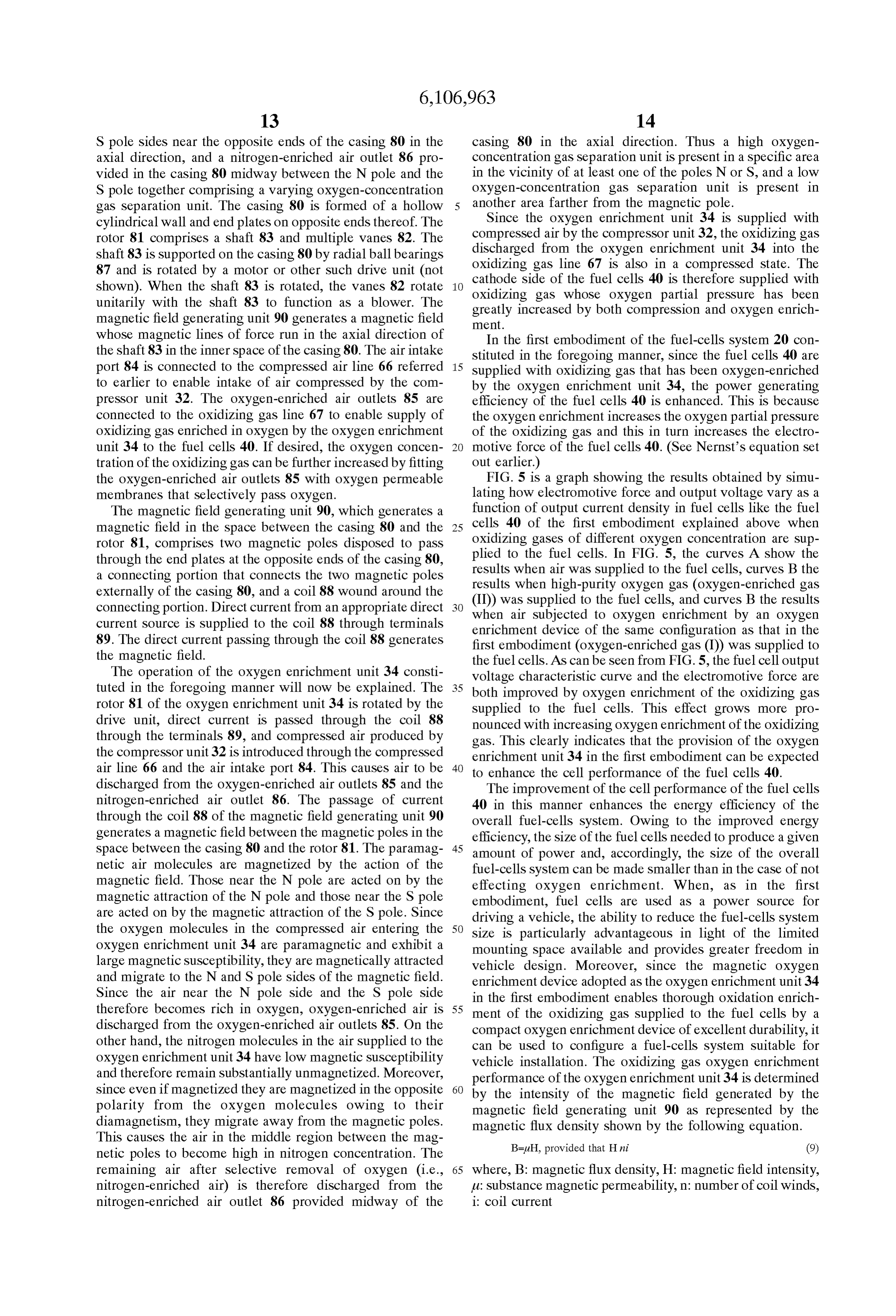
the oxygen-enriched air outlets 85 with oxygen permeable FIG. 5 is a graph showing the results obtained by simu membranes that Selectively pass oxygen. lating how electromotive force and output voltage vary as a The magnetic field generating unit 90, which generates a function of output current density in fuel cells like the fuel magnetic field in the Space between the casing 80 and the 25 cells 40 of the first embodiment explained above when rotor 81, comprises two magnetic poles disposed to pass oxidizing gases of different oxygen concentration are Sup through the end plates at the opposite ends of the casing 80, plied to the fuel cells. In FIG. 5, the curves A show the a connecting portion that connects the two magnetic poles results when air was Supplied to the fuel cells, curves B the externally of the casing 80, and a coil 88 wound around the results when high-purity oxygen gas (oxygen-enriched gas (II)) was supplied to the fuel cells, and curves B the results connecting portion. Direct current from an appropriate direct when air Subjected to oxygen enrichment by an oxygen current source is supplied to the coil 88 through terminals enrichment device of the same configuration as that in the 89. The direct current passing through the coil 88 generates first embodiment (oxygen-enriched gas (I)) was Supplied to the magnetic field. the fuel cells. As can be seen from FIG. 5, the fuel cell output The operation of the oxygen enrichment unit 34 consti Voltage characteristic curve and the electromotive force are tuted in the foregoing manner will now be explained. The 35 both improved by oxygen enrichment of the oxidizing gas rotor 81 of the oxygen enrichment unit 34 is rotated by the Supplied to the fuel cells. This effect grows more pro drive unit, direct current is passed through the coil 88 nounced with increasing oxygen enrichment of the oxidizing through the terminals 89, and compressed air produced by gas. This clearly indicates that the provision of the oxygen the compressor unit 32 is introduced through the compressed enrichment unit 34 in the first embodiment can be expected air line 66 and the air intake port 84. This causes air to be 40 to enhance the cell performance of the fuel cells 40. discharged from the oxygen-enriched air outlets 85 and the The improvement of the cell performance of the fuel cells nitrogen-enriched air outlet 86. The passage of current 40 in this manner enhances the energy efficiency of the through the coil 88 of the magnetic field generating unit 90 overall fuel-cells System. Owing to the improved energy generates a magnetic field between the magnetic poles in the efficiency, the size of the fuel cells needed to produce a given space between the casing 80 and the rotor 81. The paramag 45 amount of power and, accordingly, the Size of the overall netic air molecules are magnetized by the action of the fuel-cells System can be made Smaller than in the case of not magnetic field. Those near the N pole are acted on by the effecting oxygen enrichment. When, as in the first magnetic attraction of the N pole and those near the Spole embodiment, fuel cells are used as a power Source for are acted on by the magnetic attraction of the Spole. Since driving a vehicle, the ability to reduce the fuel-cells System the oxygen molecules in the compressed air entering the 50 Size is particularly advantageous in light of the limited oxygen enrichment unit 34 are paramagnetic and exhibit a mounting Space available and provides greater freedom in large magnetic Susceptibility, they are magnetically attracted vehicle design. Moreover, Since the magnetic oxygen and migrate to the N and Spole Sides of the magnetic field. enrichment device adopted as the oxygen enrichment unit 34 Since the air near the N pole side and the S pole side in the first embodiment enables thorough oxidation enrich therefore becomes rich in oxygen, oxygen-enriched air is 55 ment of the oxidizing gas Supplied to the fuel cells by a discharged from the oxygen-enriched air outlets 85. On the compact oxygen enrichment device of excellent durability, it other hand, the nitrogen molecules in the air Supplied to the can be used to configure a fuel-cells System Suitable for oxygen enrichment unit 34 have low magnetic Susceptibility vehicle installation. The oxidizing gas oxygen enrichment and therefore remain Substantially unmagnetized. Moreover, performance of the oxygen enrichment unit 34 is determined Since even if magnetized they are magnetized in the opposite 60 by the intensity of the magnetic field generated by the polarity from the oxygen molecules owing to their magnetic field generating unit 90 as represented by the diamagnetism, they migrate away from the magnetic poles. magnetic flux density shown by the following equation. This causes the air in the middle region between the mag B=uFH, provided that Hni (9) netic poles to become high in nitrogen concentration. The remaining air after Selective removal of oxygen (i.e., 65 where, B: magnetic flux density, H: magnetic field intensity, nitrogen-enriched air) is therefore discharged from the ti: Substance magnetic permeability, n: number of coil winds, nitrogen-enriched air outlet 86 provided midway of the i: coil current
Page 24
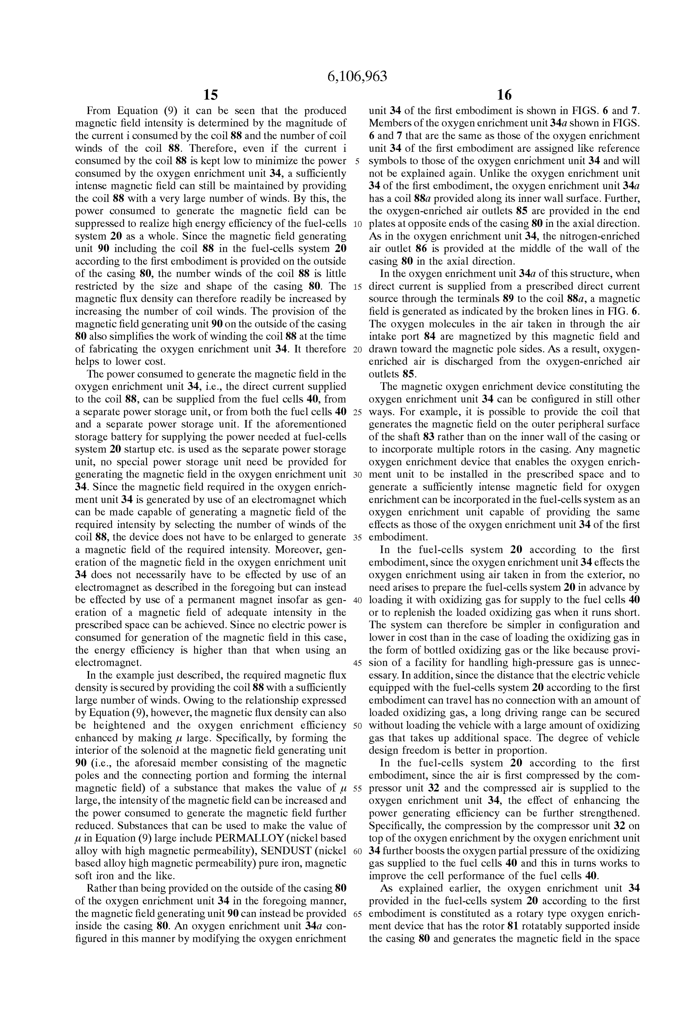
From Equation (9) it can be seen that the produced unit 34 of the first embodiment is shown in FIGS. 6 and 7. magnetic field intensity is determined by the magnitude of Members of the oxygen enrichment unit 34a shown in FIGS. the current iconsumed by the coil 88 and the number of coil 6 and 7 that are the same as those of the oxygen enrichment winds of the coil 88. Therefore, even if the current i unit 34 of the first embodiment are assigned like reference consumed by the coil 88 is kept low to minimize the power symbols to those of the oxygen enrichment unit 34 and will consumed by the oxygen enrichment unit 34, a Sufficiently not be explained again. Unlike the Oxygen enrichment unit intense magnetic field can Still be maintained by providing 34 of the first embodiment, the oxygen enrichment unit 34a the coil 88 with a very large number of winds. By this, the has a coil 88a provided along its inner wall surface. Further, power consumed to generate the magnetic field can be the oxygen-enriched air outlets 85 are provided in the end Suppressed to realize high energy efficiency of the fuel-cells plates at opposite ends of the casing 80 in the axial direction. System 20 as a whole. Since the magnetic field generating AS in the oxygen enrichment unit 34, the nitrogen-enriched unit 90 including the coil 88 in the fuel-cells system 20 air outlet 86 is provided at the middle of the wall of the according to the first embodiment is provided on the outside casing 80 in the axial direction.
of the casing 80, the number winds of the coil 88 is little In the oxygen enrichment unit 34a of this structure, when restricted by the size and shape of the casing 80. The 15 direct current is Supplied from a prescribed direct current magnetic flux density can therefore readily be increased by Source through the terminals 89 to the coil 88a, a magnetic increasing the number of coil winds. The provision of the field is generated as indicated by the broken lines in FIG. 6. magnetic field generating unit 90 on the outside of the casing The oxygen molecules in the air taken in through the air 80 also simplifies the work of winding the coil 88 at the time intake port 84 are magnetized by this magnetic field and of fabricating the oxygen enrichment unit 34. It therefore drawn toward the magnetic pole sides. As a result, oxygen helps to lower cost. enriched air is discharged from the oxygen-enriched air The power consumed to generate the magnetic field in the outlets 85.
oxygen enrichment unit 34, i.e., the direct current Supplied The magnetic oxygen enrichment device constituting the to the coil 88, can be supplied from the fuel cells 40, from oxygen enrichment unit 34 can be configured in Still other a separate power Storage unit, or from both the fuel cells 40 25 ways. For example, it is possible to provide the coil that and a separate power Storage unit. If the aforementioned generates the magnetic field on the Outer peripheral Surface Storage battery for Supplying the power needed at fuel-cells of the shaft 83 rather than on the inner wall of the casing or System 20 startup etc. is used as the Separate power Storage to incorporate multiple rotors in the casing. Any magnetic unit, no special power Storage unit need be provided for oxygen enrichment device that enables the oxygen enrich generating the magnetic field in the oxygen enrichment unit ment unit to be installed in the prescribed Space and to 34. Since the magnetic field required in the Oxygen enrich generate a Sufficiently intense magnetic field for oxygen ment unit 34 is generated by use of an electromagnet which enrichment can be incorporated in the fuel-cells System as an can be made capable of generating a magnetic field of the OXygen enrichment unit capable of providing the same required intensity by Selecting the number of winds of the effects as those of the oxygen enrichment unit 34 of the first coil 88, the device does not have to be enlarged to generate 35 embodiment.
a magnetic field of the required intensity. Moreover, gen In the fuel-cells system 20 according to the first eration of the magnetic field in the oxygen enrichment unit embodiment, Since the oxygen enrichment unit 34 effects the 34 does not necessarily have to be effected by use of an oxygen enrichment using air taken in from the exterior, no electromagnet as described in the foregoing but can instead need arises to prepare the fuel-cells System 20 in advance by be effected by use of a permanent magnet insofar as gen 40 loading it with oxidizing gas for Supply to the fuel cells 40 eration of a magnetic field of adequate intensity in the or to replenish the loaded oxidizing gas when it runs short. prescribed Space can be achieved. Since no electric power is The System can therefore be simpler in configuration and consumed for generation of the magnetic field in this case, lower in cost than in the case of loading the oxidizing gas in the energy efficiency is higher than that when using an the form of bottled oxidizing gas or the like because provi electromagnet. 45 Sion of a facility for handling high-pressure gas is unnec In the example just described, the required magnetic flux essary. In addition, Since the distance that the electric Vehicle density is secured by providing the coil 88 with a sufficiently equipped with the fuel-cells System 20 according to the first large number of winds. Owing to the relationship expressed embodiment can travel has no connection with an amount of by Equation (9), however, the magnetic flux density can also loaded oxidizing gas, a long driving range can be Secured be heightened and the oxygen enrichment efficiency 50 without loading the vehicle with a large amount of oxidizing enhanced by making it large. Specifically, by forming the gas that takes up additional Space. The degree of vehicle interior of the Solenoid at the magnetic field generating unit design freedom is better in proportion. 90 (i.e., the aforesaid member consisting of the magnetic In the fuel-cells system 20 according to the first poles and the connecting portion and forming the internal embodiment, Since the air is first compressed by the com magnetic field) of a Substance that makes the value of u. 55 preSSor unit 32 and the compressed air is Supplied to the large, the intensity of the magnetic field can be increased and oxygen enrichment unit 34, the effect of enhancing the the power consumed to generate the magnetic field further power generating efficiency can be further Strengthened. reduced. Substances that can be used to make the value of Specifically, the compression by the compressor unit 32 on u in Equation (9) large include PERMALLOY (nickelbased top of the oxygen enrichment by the oxygen enrichment unit alloy with high magnetic permeability), SENDUST (nickel 60 34 further boosts the oxygen partial pressure of the oxidizing based alloy high magnetic permeability) pure iron, magnetic gas supplied to the fuel cells 40 and this in turns works to Soft iron and the like. improve the cell performance of the fuel cells 40. Rather than being provided on the outside of the casing 80 AS explained earlier, the oxygen enrichment unit 34 of the oxygen enrichment unit 34 in the foregoing manner, provided in the fuel-cells system 20 according to the first the magnetic field generating unit 90 can instead be provided 65 embodiment is constituted as a rotary type oxygen enrich inside the casing 80. An oxygen enrichment unit 34a con ment device that has the rotor 81 rotatably supported inside figured in this manner by modifying the oxygen enrichment the casing 80 and generates the magnetic field in the Space
Page 25
between the rotor 81 and the casing 80. However, another controlling the pressure control valve 86c and the amount of type of magnetic oxygen enrichment device can be used oxidizing gas Supplied to the fuel cells 40 can be regulated instead. For instance, a piston type or batch type oxygen by controlling the flow rate control valve 85c. enrichment device can be adopted. Use of a rotary type When the compressor 72b is rotated, air is taken in oxygen enrichment device as in the first embodiment is, through the air intake port 84 and compressed as explained however, advantageous over use of other types of magnetic above. At the same time, oxygen molecules present in the air oxygen enrichment devices in Such points as Oxygen yield are Separated by the action of the magnetic field. The during oxygen enrichment (oxygen concentration of the paramagnetic OXygen molecules are magnetized in the mag oxygen-enriched air produced), flow rate of the oxygen netic field and migrate toward the N pole. The compressor enriched air produced, and performance during continuous 72b driven by rotation of the turbine 72a takes in air through operation. the air intake port 84 and compresses it. Compressed In the first embodiment, the compressor unit 32 and the oxygen-enriched air is therefore discharged from the oxygen enrichment unit 34 are provided as Separate units oxygen-enriched air outlet 85b to be supplied to the cathode and the air compressed by the compressor unit 32 is Supplied side of the fuel cells 40 through the oxidizing gas line 67. to the oxygen enrichment unit 34. Instead, however, the 15 Although the oxygen enrichment unit 34b of the second compressor and the oxygen enrichment unit can be inte embodiment uses a permanent magnet to generate the mag grated and the compression and oxygen enrichment of air be netic field for oxygen Separation, it can instead use an conducted Simultaneously. A Second embodiment of the electromagnet for this purpose as in the first embodiment. invention configured in this manner will now be explained. In the fuel-cells system 20b according to the second FIG. 8 is a block diagram schematically illustrating the embodiment configured in the foregoing manner, Since the structure of a fuel-cells system 20b that is a second embodi magnetic oxygen enrichment device built into the interior of ment of the invention. Since the fuel-cells system 20b the compressor unit 72 produces oxygen-enriched air that is according to the Second embodiment is configured Similarly Supplied to the fuel cells 40 as oxidizing gas, effects similar to the fuel-cells system 20 of the first embodiment, members to those of the fuel-cells system 20 according to the first thereofthat are the same as those of the first embodiment are 25 embodiment can be obtained. Since a magnetic oxygen assigned like reference Symbols to those of the first embodi enrichment device is incorporated into the interior of the ment and will not be explained again. Unlike the fuel-cells compressor unit 72 in the fuel-cells system 20b according to system 20, the fuel-cells system 20b is equipped with a the Second embodiment, compression and oxygen enrich compressor unit 72 that internally incorporates an oxygen ment of the air can be effected simultaneously. This structure enrichment unit 34b constituted as a magnetic oxygen also ensures the extremely high efficiency of oxygen enrich enrichment device. Like the compressor unit 32 of the first ment. The overall structure of the system is therefore sim embodiment, the compressor unit 72 also compresses air but plified and made more compact. The Simplification of the it also simultaneously conducts oxygen enrichment. FIG. 9 System structure is a particular advantage when the fuel-cells shows the structure of the compressor 72. system 20b is installed in a vehicle and the fuel cells are Like the compressor unit 32 of the first embodiment, the 35 utilized as a power Source for driving the vehicle, because it compressor unit 72 has a turbine 72a and a compressor 72b increases the freedom of vehicle design. that are connected by a shaft 72c. The components are In the fuel-cells system 20b according to the second housed in a casing 80b. As in the first embodiment, the embodiment, since the oxygen enrichment unit 34b is built turbine 72a is driven by combustion gas supplied from the into the interior of the compressor unit 72, the oxygen burner 30 to thereby rotate the compressor 72b and cause it 40 enrichment device can be driven by high-pressure gas dis to compress air taken in from the compressor 72b Side. In the charged from a prescribed member constituting the fuel compressor unit 72, the oxygen enrichment unit 34b is cells system (combustion gas supplied by the burner 30 in formed by the compressor 72b and the Surrounding region. the Second embodiment). Since no energy therefore need be In the peripheral region of the compressor 72b, the N pole consumed especially for driving the magnetic oxygen of a permanent magnet is disposed on the Side corresponding 45 enrichment device, the increase in the oxygen partial pres to an end portion of the compressor unit 72 and the S pole Sure of the oxidizing gas Supplied to the fuel cells is not of the permanent magnet is disposed on the Side correspond achieved at the expense of the energy efficiency of the ing to the middle portion of the compressor unit 72, whereby overall fuel-cells System.
a magnetic field is produced at the peripheral region of the In the oxygen enrichment unit 34b of the compressor unit compressor 72b in the axial direction of the compressor unit 50 72 of the second embodiment, since the volume of the space 72. The compressor unit 72 is provided axially outward of between the casing 80b and the compressor 72b is formed to the compressor 72b with an air intake port 84b for taking be Smaller in the vicinity of the oxygen-enriched air outlet outside air into the compressor unit 72 through the air intake 85b than in the vicinity of the residual air outlet 86b, oxygen, line 65. The casing 80b of the compressor unit 72 is formed which is contained in air at a lower content than nitrogen, toward the axially outward end of the compressor 72b with 55 can be more effectively enriched. Specifically, the migration an oxygen-enriched air outlet 85b and toward the axially of the magnetized oxygen molecules toward the narrower inward end thereof with a residual air outlet 86b. The Side of Smaller Volume heightens the effect of oxygen impeller of the compressor 72b is of small radius and tapers enrichment in the vicinity of the oxygen-enriched air outlet outward. As the casing 80b follows the shape of the com 85b and thus enables Supply of more highly oxygen pressor 72b, the volume of the space between the casing 80b 60 enriched oxidizing gas to the fuel cells 40. and the compressor 72b also decreases outward. The AS explained above, in the oxygen enrichment unit 34b of residual air outlet 86b is provided with a pressure control the second embodiment, the oxygen-enriched air outlet 85b valve 86c and the oxygen-enriched air outlet 85b is provided is provided only at the end of the oxygen enrichment unit with a flow rate control valve 85c. The pressure control 34b on the side thereof having smaller internal volume so as valve 86c and the flow rate control valve 85c are connected 65 to obtain oxidizing gas having higher oxygen partial pres to the control unit 50, which controls their drive states. The Sure. However, Since the oxygen molecules magnetized by preSSure State inside the casing 80b can be regulated by the magnetic field in the oxygen enrichment unit 34b shown
Page 26
in FIG. 9 migrate toward both the N pole and the S pole, the fuel cells 40 to compress the oxidizing gas Supplied to oxygen enrichment also occurs on the Side of the oxygen the fuel cells 40. In this arrangement, a gear mechanism can enrichment unit 34 having larger internal Volume, i.e., at the be provided to establish a gear ratio between the turbine and end on the side provided with the residual air outlet 86b. It compressor Sides of the compressor unit 74 So as to Secure is also therefore possible to provide an oxygen-enriched air the rotational Speed on the compressor Side needed to ensure outlet in the oxygen enrichment unit 34b at its end toward that the oxidizing gas Supplied to the fuel cells 40 is the Side provided with the Spole and to discharge Oxygen increased to a Sufficiently high level. When the oxidizing gas enriched air from the vicinity of both magnetic poles. In this cannot be Sufficiently compressed by the energy of the case, a nitrogen-enriched air outlet can be provided midway between the magnetic poles Similarly to the oxygen enrich exhaust oxidizing gas discharged by the fuel cells 40 alone, ment unit 34 in the first embodiment. When oxygen to achieve of the energy the exhaust oxidizing gas can be Supplemented adequate oxidizing gas compression.
enriched air is harvested from the vicinity of both poles, the croSS-Sectional area of the oxygen enrichment unit can be oxygen enrichment unit iswill
A fourth embodiment now be explained in which the driven using combustion exhaust made uniform throughout, without the aforesaid volume gas discharged by the heater-Vaporizer of the fuel-cells change, as in the oxygen enrichment unit 34 of the first 15 System. FIG. 11 is a block diagram Schematically illustrating embodiment.
In the Second embodiment, the Oxygen enrichment unit the structure of a fuel-cells system 20d that is a fourth 34b constituted as a magnetic oxygen enrichment device is embodiment of the invention. Since the fuel-cells system incorporated into the interior of the compressor unit 72 and 20d is configured similarly to the fuel-cells system 20 this magnetic oxygen enrichment device is driven by Sup according to the first embodiment, members thereof that are plying combustion gas produced by the burner 30 to the the same as those of the first embodiment are assigned like compressor unit 72. The magnetic oxygen enrichment reference symbols to those of the first embodiment and will device can, however, instead be driven using high-pressure not be explained again. The fuel-cells System 20d according gas produced by members constituting the fuel-cells System to the fourth embodiment is equipped with an oxygen other than the burner 30. A third embodiment of the inven enrichment unit 34d. The oxygen enrichment unit 34d is tion configured in this manner will now be explained. 25 incorporated into the interior of a compressor unit 76 driven FIG. 10 is a block diagram schematically illustrating the by combustion exhaust gas discharged from the heater structure of a fuel-cells system 20c that is a third embodi vaporizer 27. Specifically, in the fuel-cells system 20d ment of the invention. Since the fuel-cells system 20c is according to the fourth embodiment, the compressor unit 76, configured Similarly to the fuel-cells System 20 according to which is similar to the compressor unit 72 provided in the the first embodiment, members thereof that are the same as fuel-cells System 20b according to the Second embodiment, those of the first embodiment are assigned like reference is driven not by combustion gas supplied from the burner 30 symbols to those of the first embodiment and will not be but instead by combustion exhaust gas discharged from the explained again. The fuel-cells System 20c according to the heater-vaporizer 27. In this fuel-cells System 20d, the com third embodiment is equipped with an oxygen enrichment bustion gas produced by the burner 30 is supplied directly to unit 34c. The oxygen enrichment unit 34c is incorporated 35 the heater-vaporizer 27 of the fuel reformer 26 as in the third into the interior of a compressor unit 74 driven by exhaust embodiment.
oxidizing gas discharged from the fuel cells 40. Specifically, The effects that the earlier embodiments achieve by in the fuel-cells system 20c according to the third Supplying oxygen-enriched, compressed air to the fuel cells embodiment, the compressor unit 74, which is similar to the as the oxidizing gas are also achieved by the fuel-cells compressor unit 72 provided in the fuel-cells system 20b 40 system 20d according to the fourth embodiment. In addition, according to the Second embodiment, is driven not by like the Second and third embodiments, the fuel-cells System combustion gas supplied from the burner 30 but instead by 20d also achieves a simplified configuration by incorporat exhaust oxidizing gas discharged from the fuel cells 40. In ing the oxygen enrichment unit into the compressor unit. this fuel-cells System 20c, the combustion gas produced by Moreover, in the fuel-cells system 20d, the compressor unit the burner 30 is supplied directly to the heater-vaporizer 27 45 76 incorporating the oxygen enrichment unit 34d is driven of the fuel reformer 26. After having been used to drive the by combustion exhaust gas discharged from the heater compressor unit 74, the exhaust oxidizing gas is delivered to Vaporizer 27. Since no energy therefore need be consumed the condensed water recovery vessel 36 as in the earlier especially for driving the oxygen enrichment unit 34d, the embodiments. oxygen enrichment of the oxidizing gas by the oxygen The effects that the first and second embodiments achieve 50 enrichment unit 34d is not achieved at the expense of the by Supplying oxygen-enriched, compressed air to the fuel energy efficiency of the overall fuel-cells system 20d. cells as the oxidizing gas are also achieved by the fuel-cells In each of the second to fourth embodiments described in system 20c according to the third embodiment. In addition, the foregoing, a compressor unit incorporating the oxygen like the fuel-cells system 20b according to the second enrichment unit is driven by high-pressure gas discharged embodiment, the fuel-cells system 20c also achieves a 55 from a prescribed member constituting the fuel-cells System. Simplified configuration by incorporating the oxygen enrich Another possible arrangement is to effect oxygen enrich ment unit into the compressor unit. Moreover, in the fuel ment of air using multiple oxygen enrichment units in cells System 20c, the compressor unit 74 incorporating the combination and to drive the multiple oxygen enrichment oxygen enrichment unit 34c is driven by exhaust oxidizing units using high-pressure gas discharged from multiple gas discharged from the fuel cells 40. Since no energy 60 members constituting the fuel-cells system. A fifth embodi therefore need be consumed especially for driving the oxy ment of this invention configured in this manner will now be gen enrichment unit 34c, the oxygen enrichment of the explained. FIG. 12 is a block diagram Schematically illus oxidizing gas by the oxygen enrichment unit 34c is not trating the structure of a fuel-cells system 20e that is a fifth achieved at the expense of the energy efficiency of the embodiment of the invention. Since the fuel-cells system overall fuel-cells system 20c. 65 20e is configured similarly to the fuel-cells system 20 AS explained in the foregoing, the compressor unit 74 according to the first embodiment, members thereof that are uses the energy of the exhaust oxidizing gas discharged from the same as those of the first embodiment are assigned like
Page 27
reference symbols to those of the first embodiment and will Stream of the compreSSor unit 32f. Air taken in from outside not be explained again. The fuel-cells System 20e according is Successively compressed by the compressor units 32d, 32e to the fifth embodiment is equipped with compressor units and 32f respectively driven by the exhaust oxidizing gas 72e, 74e and 76e. Each of these compressor units internally discharged from the fuel cells 40, the combustion exhaust incorporates an oxygen enrichment unit. The compressor gas discharged from the heater-Vaporizer 27 and the com unit 72e has the same structure as the compressor unit 72 of bustion gas Supplied from the burner 30. The compressed air the second embodiment described earlier and is driven by is oxygen-enriched by the oxygen enrichment unit 34f and the combustion gas supplied from the burner 30. The com Supplied to the fuel cells 40 as oxidizing gas. preSSor unit 74e has the Same Structure as the compressor The effects achieved by the fuel-cells system 20e accord unit 74 of the third embodiment described earlier and is ing to the fifth embodiment achieves are also achieved by the driven by the exhaust oxidizing gas discharged from the fuel fuel-cells system 20f. The fuel-cells system 20f thoroughly cells 40. The compressor unit 76e has the same structure as utilizes the high-pressure gases discharged from multiple the compressor unit 76 of the fourth embodiment described members provided in the fuel-cells System to compress air above and is driven by the combustion exhaust gas dis and elevates the oxygen partial pressure of the oxidizing gas, charged from the heater-vaporizer 27. In the fuel-cells 15 thereby enhancing the power generating efficiency of the System 20e, air taken in from outside is first compressed and fuel cells 40.
oxygen-enriched by the compressor unit 74e, thereafter In the fuel-cells system 20f just described, the oxygen compressed and oxygen-enriched by the compressor unit enrichment unit 34f is disposed in the line for Supplying 76e, then compressed and oxygen-enriched by the compres oxidizing gas to the fuel cells 40 at a position downstream Sor unit 72e and finally supplied to the fuel cells 40. of the compressor units 32d, 32e and 32f. However, it is The effects that the earlier embodiments achieve by possible in a similar fuel-cells System to replace the oxygen Supplying oxygen-enriched, compressed air to the fuel cells enrichment unit 34f with an oxygen enrichment unit incor as the oxidizing gas are also achieved by the fuel-cells porated in one of the compressor units. For instance, the system 20e according to the fifth embodiment. In addition, most downstream compressor unit 32f only can be replaced like the second to fourth embodiments, the fuel-cells system 25 with a compressor unit like the compressor unit 72e pro 20e also achieves a simplified configuration by incorporat vided in the fuel-cells system 20e of the fifth embodiment, ing the oxygen enrichment units into the compressor units. i.e., with a compressor unit internally incorporating an Moreover, in the fuel-cells system 20e, the multiple com oxygen enrichment device. With this arrangement, too, the preSSor units incorporating the oxygen enrichment units are high-pressure gases discharged from multiple members pro driven by utilizing high-pressure gases discharged from vided in the fuel-cells system can be thoroughly utilized to multiple members constituting the fuel-cells System 20e. compress air and elevate the oxygen partial preSSure of the The provision of multiple compressor units internally incor oxidizing gas, thereby enhancing the power generating effi porating oxygen enrichment units in this manner enables a ciency of the fuel cells 40.
further improvement in the efficiency of air compression and In the fuel-cells system 20e and the fuel-cells system 20f oxygen enrichment. It also reduces the amount of unutilized 35 according to the fifth embodiment explained in the energy released from the fuel-cells system 20e, thereby foregoing, the multiple compressor units are connected So enhancing effective energy utilization. Of particular note is that the gases that drive the compressor units are, in order, that in this fifth embodiment the multiple compressors are the exhaust oxidizing gas discharged from the fuel cells 40, connected in order from the one driven by the high the combustion exhaust gas discharged from the heater temperature gas with the least energy to the one driven by 40 Vaporizer 27 and the combustion gas Supplied by the burner the high-pressure gas with the greatest energy. By this, the 30. This order is, however, preferably modified in light of compression efficiency and the oxygen enrichment effi the actual operating condition of the fuel-cells System. For ciency in the process of producing the oxidizing gas Sup example, when the energy of the exhaust oxidizing gas plied to the fuel cells 40 can be optimized and the oxygen discharged from the fuel cells 40 is greater than that of the partial pressure of the oxidizing gas maximized. 45 combustion exhaust gas discharged from the heater In the fuel-cells system 20e shown in FIG. 12, it is Vaporizer 27, the compressor unit 74e or compressor unit possible to replace the compressor units 72e, 74e and 76e 32d driven by the exhaust oxidizing gas is preferably with compressor units that do not incorporate oxygen connected upstream of the compressor unit 76e or the enrichment units and to provide a Separate oxygen enrich compressor unit 32e.
ment unit downstream of the lines connecting the compres 50 In the fuel-cells system 20e and the fuel-cells system 20f Sor units. A fuel-cells System 20f configured in this manner explained in the foregoing, the combustion gas Supplied is shown in FIG. 13. Since the fuel-cells system 20f is from the burner 30, the combustion exhaust gas discharged configured Similarly to the fuel-cells System 20 according to from the heater-vaporizer 27 and the exhaust oxidizing gas the first embodiment, members thereof that are the same as discharged from the fuel cells 40 are used to compress the those of the first embodiment are assigned like reference 55 oxidizing gas supplied to the fuel cells 40. However, not all symbols to those of the first embodiment and will not be of these high-pressure gases need be utilized. It Suffices, for explained again. The fuel-cells System 20f is equipped with example, to utilize two of these three high-temperature compressor units 32d, 32e and 32f and an oxygen enrich gases. Use can also be made of high-pressure gases dis ment unit 34f. The compressors units 32d, 32e and 32f have charged by other members constituting the fuel-cells System the same Structure as the compressor unit 32 of the fuel-cells 60 or by prescribed members constituting the electric Vehicle in System 20 according to the first embodiment. The oxygen which the fuel-cells System is installed. In any case, the enrichment unit 34f has the same Structure as the oxygen oxidizing gas can be compressed without energy waste if the enrichment unit 34 of the fuel-cells system 20. The com high-pressure gases are used for compression in order from pressor units 32d, 32e and 32fare respectively installed at that having the least energy to that having the greatest the same locations as the compressor units 74e, 76e and 72e 65 energy.
in the fuel-cells system 20e according to the fifth embodi The oxygen enrichment units of the fuel-cells Systems ment. The oxygen enrichment unit 34f is provided down according to the embodiments described in the foregoing
Page 28
take advantage of the fact that oxygen molecules are para are equal to each other, the temperature of the cooled air magnetic. Specifically, as explained above they utilize the discharged from the cold air vent can be regulated by migration of the oxygen molecules toward the poles to effect controlling a control valve that regulates the amount of oxygen enrichment. Since oxygen molecules are warm air discharged from the warm air vent. The cooled air paramagnetic, their magnetic Susceptibility, a factor affect discharged from the cooler 78 is oxygen-enriched by the ing oxygen enrichment, is defined by Curie's law: oxygen enrichment unit 34g. The cooled air discharged by the cooler 78 and Supplied to the oxygen enrichment unit =CT (10) 34g is at approximately atmospheric pressure. The oxygen X: Magnetic Susceptibility of oxygen enriched air discharged from the oxygen enrichment unit 34g is therefore forwarded to the compressor unit 32h to be
C: Curie constant compressed before Supply as oxidizing gas to the fuel cells T: Absolute temperature 40.
From Curie's law it follows that the magnetic suscepti The effects that the earlier described embodiments bility of oxygen increases with decreasing absolute tempera achieve by Supplying compressed, oxygen-enriched air to ture. In other words, the farther the temperature of the air 15 the fuel cells as the oxidizing gas are also achieved by the Supplied to an oxygen enrichment device is lowered, the fuel-cells System 20g according to the Sixth embodiment. greater will be the magnetic Susceptibility of the Oxygen and Moreover, Since the fuel-cells System 20g is equipped to the higher will be the oxygen enrichment yield (oxygen Supply cooled air to the magnetic oxygen enrichment unit concentration of the oxygen-enriched air produced) in the 34g, the oxygen enrichment yield (oxygen concentration of oxygen enrichment device. A sixth embodiment of the the oxygen-enriched air produced) in the oxygen enrichment invention will now be explained which is configured So that unit 34g is enhanced. Since this embodiment uses the vortex during the elevation of the oxygen partial pressure of an cooler described above to cool the air Supplied to the oxygen oxidizing gas by use of a magnetic oxygen enrichment enrichment unit 34g, compressed air can be cooled simply device the Oxygen partial pressure of the oxidizing gas is by supplying it to the cooler 78. The provision of the cooler further increased by lowering the temperature of the air 25 78 therefore does not complicate the structure of the overall Supplied to the oxygen enrichment device. fuel-cells System. Moreover, Since no special energy Supply FIG. 14 is a block diagram schematically illustrating the means is needed for cooling the air Supplied to the oxygen structure of a fuel-cells system 20g that is a sixth embodi enrichment unit 34g, the energy efficiency of the fuel-cells ment of the invention. Since the fuel-cells system 20g is System 20g as a whole is not degraded. configured Similarly to the fuel-cells System 20 according to The fuel-cells system 20g uses the compressor unit 32h the first embodiment, members thereof that are the same as driven by the combustion exhaust gas discharged from the those of the first embodiment are assigned like reference heater-vaporizer 27 to increase the preSSure of the oxygen Symbols to those of the first embodiment and will not be enriched oxidizing gas from the oxygen enrichment unit 34g explained again. The fuel-cells System 20g according to the to the prescribed pressure required for the electrochemical Sixth embodiment is equipped with a compressor unit 32g 35 reactions in the fuel cells 40. AS the energy Source for driven by the combustion gas Supplied from the burner 30, driving this type of compressor unit, it is possible not only a compressor unit 32h driven by the combustion exhaust gas to use the combustion exhaust gas from the heater-vaporizer discharged from the heater-vaporizer 27, a cooler 78 and an 27 utilized by the compressor unit 32h but also to use the oxygen enrichment unit 34g. In the fuel-cells System 20g, air exhaust oxidizing gas discharged from the fuel cells 40. taken in from outside is first compressed by the compressor 40 However, use of the combustion exhaust gas discharged unit 32g and supplied to the cooler 78. The cooler 78 cools from the heater-vaporizer 27 as in this embodiment enables the compressed air and Supplies the cooled compressed air the oxidizing gas to be compressed more quickly at Startup to the oxygen enrichment unit 34g. The air enriched in of the fuel-cells system 20g. This is because once heating of oxygen by the oxygen enrichment unit 34g is Supplied to the the heater-vaporizer 27 by the burner 30 begins with startup compressor unit 32h, compressed and Supplied as oxidizing 45 of the fuel-cells system 20g, the heater-vaporizer 27 gas to the fuel cells 40. The oxygen enrichment unit 34g is promptly commences to discharge combustion exhaust gas configured Similarly to the oxygen enrichment unit 34 of the that the compressor unit 32h uses to compress reformed gas fuel-cells system 20 according to the first embodiment. The for supply to the fuel cells 40.
compressor units 32g, 32h are configured similarly to the Although the fuel-cells System 20g according to the Sixth compressor unit 32 of the first embodiment. 50 embodiment uses a vortex cooler for cooling air Supplied to The cooler 78 in this embodiment is a vortex cooling the oxygen enrichment unit 34g, other types of coolers can apparatus (Vortex Tube, product of Vortec Inc.). When also be used. A configuration using another type of cooler Supplied with compressed air, the Vortex cooler can deliver will now be explained as the seventh embodiment of the cooled air without being Specially Supplied with energy for invention. FIG. 15 is a block diagram schematically illus cooling. The compressed air compressed by the compressor 55 trating the structure of a fuel-cells system 20h that is a unit 32g and supplied into the cooler 78 through the com Seventh embodiment of the invention. Since the fuel-cells pressed air line 66 forms a vortex in the tube of the cooler system 20h is configured similarly to the fuel-cells system and rotates at high Speed. Part of the rapidly rotating air 20 according to the first embodiment, members thereof that forming an outer Vortex in the tube is discharged as warm air are the same as those of the first embodiment are assigned from a warm air vent provided at one end of the cooler 78. 60 like reference symbols to those of the first embodiment and The remaining air forms an inner Vortex to move inside the will not be explained again. The fuel-cells system 20h outer Vortex in the opposite direction and to be vented from according to the Seventh embodiment is equipped with a a cold air vent provided at the other end of the cooler 78. compressor unit 32i driven by the combustion gas Supplied Since the quantity of heat Supplied to the outer Vortex from the burner 30, a coolant pump 91 driven by the rotating and moving along the inner wall of the tube and the 65 combustion exhaust gas discharged from the heater quantity of heat removed from the inner Vortex that moves vaporizer 27, an absorbent pump 92 driven by the exhaust and rotates in the reversed direction inside the outer Vortex oxidizing gas discharged from the fuel cells 40, a low-power
Page 29
absorption cooler 93, a heat exchanger 95 for cooling Sor unit 32i, it is also provided inside with a high compressed air by effecting heat eXchange between the air temperature regenerator 101. The high-temperature regen compressed by the compressor unit 32i and the cold water erator 101 heats the dilute absorbent to concentrate it by cooled by the cooler 93, and an oxygen enrichment unit 34h driving out Steam . The absorbent concentrated by the for oxygen-enriching cooled compressed air Supplied from high-temperature regenerator 101 is Sent to a low the heat exchanger 95. temperature regenerator 102 where it is further concentrated. The compressor unit 32i is for compressing air taken in The steam driven out of the absorbent by the high from outside and Supplying the compressed air to the oxygen temperature regenerator 101 is forwarded to the low enrichment unit 34h through the heat exchanger 95. It is of temperature regenerator 102 through a steam line 103. The the Same configuration as the compressor unit 32 of the low-temperature regenerator 102 uses the heat of the Steam fuel-cells system 20 according to the first embodiment. The for further concentration of the absorbent. oxygen enrichment unit 34h, which is of the same configu ration as the oxygen enrichment unit 34 of the fuel-cells lowTheSopressure of the low-temperature regenerator 102 is set as to have a lower boiling point than the high
System 20 according to the first embodiment, receives and temperature regenerator 101. The Steam generated in the oxygen-enriches the compressed air cooled by the heat eXchanger 95 and Supplies the oxygen-enriched air to the 15 high-temperature regenerator 101 is sent to the low fuel cells 40 as oxidizing gas. The coolant pump 91 receives temperature regenerator 102 where its heat is used to heat power from the combustion exhaust gas discharged from the and further concentrate the absorbent. The absorbent con heater-vaporizer 27 for circulation of coolant in the cooler centrated by the low-temperature regenerator 102 is again 93. The absorbent pump 92, which obtains power from the dripped into the absorber 97 through the concentrated absor exhaust oxidizing gas discharged by the fuel cells 40, pumps bent line 99 and used to absorb the evaporated refrigerant. liquid absorbent from the cooler 93 and supplies it to the The Steam forwarded to the low-temperature regenerator burner 30. The coolant pump 91 and the absorbent pump 92 102 through the steam line 103 falls in temperature upon are equipped with impellers rotated by the respective gases. being used to heat the absorbent and is then further cooled In each pump, the power of the impeller is transferred and condensed by an appropriate coolant in a condensed through a shaft to effect the pumping operation. The portion 25 water recovery vessel 104 formed integrally with the low of the fuel-cells system 20h shown in FIG. 15 related to temperature regenerator 102. The water condensed in the cooling of compressed air is shown in detail in FIG. 16. condensed water recovery vessel 104 is supplied through the The cooling operation effected mainly by the cooler 93 refrigerant line 98 to the evaporator 96 and dripped as will now be explained with reference to FIG. 16. The cooler refrigerant on the cooant line 94.
93, an absorption cooling device, comprises an evaporator The coolant used to condense Steam in the condensed 96 and an absorber 97 integrated as a single unit. Coolant is water recovery vessel 104 flows through a coolant line 105, circulated between the evaporator 96 and the heat exchanger which forms a closed loop connecting the condensed water 95 through a coolant line 94. A refrigerant (water in this recovery vessel 104, the absorber 97, a heat exchanger 106, embodiment) is supplied to the evaporator 96 through a and the coolant pump 91. The coolant in the coolant line 105 refrigerant line 98. The refrigerant is dripped onto the 35 is circulated through this loop by the coolant pump 91. After portion of the coolant line 94 disposed inside the evaporator being cooled in the heat eXchanger 106, the coolant first goes 96. The interior space of the evaporator 96 and the absorber to the absorber 97, where it removes heat produced when the 97 is vacuumized to around several mmHg. The dripped refrigerant Steam is absorbed by the absorbent. It then goes refrigerant evaporates to absorb heat of vaporization from to the condensed water recovery vessel 104, where it cools the coolant in the coolant line 94. The coolant cooled in this 40 Steam and restores it to liquid refrigerant. After having its manner is circulated through the coolant line 94 and used in temperature raised in the absorber 97 and the condensed the heat eXchanger 95 to cool the compressed air Supplied water recovery vessel 104, the coolant is cooled in the heat from the compressor unit 32i. The compressed air cooled in eXchanger 106, whereafter the same operation is repeated. the heat eXchanger 95 is Supplied to the oxygen enrichment Since the fuel-cells system 20h according to this embodi unit 34 for oxygen enrichment and then to the fuel cells 40 45 ment first cools air taken in from outside and then Supplies as oxidizing gas. Thus in the fuel-cells System 20 of this the cooled air to the oxygen enrichment unit, it can achieve embodiment the operation for cooling the air Supplied to the the same effect as the fuel-cells System 20g according to the oxygen enrichment unit 34h is conducted mainly by the sixth embodiment. Moreover, in the fuel-cells system 20h evaporator 96 and the heat exchanger 95 of the cooler 93. according to this embodiment, the cooler 93, unlike the The coolant raised in temperature by heat eXchange with the 50 cooler 78 of the sixth embodiment, does not cause a large compressed air in the heat exchanger 95 is returned to the decrease in the pressure of the once compressed air during evaporator 96 for cooling, whereafter the foregoing opera the cooling operation. Highly compressed and cooled gas tion is repeated. can therefore be obtained by Supplying compressed air to the In the absorber 97, which like the evaporator 96 is also cooler 93 and no need arises to recompress the oxygen vacuumized, liquid absorbent (aqueous Sodium bromide 55 enriched oxidizing gas at the time of Supplying it to the fuel Solution in this embodiment) is dripped from a concentrated cells. The fuel-cells System therefore has a simple configu absorbent line 99. The dripped absorbent is diluted by ration and is not lowered in energy efficiency owing to absorption of steam in the absorber 97. The steam absorbed oxidizing gas recompression. Still, if recompression is found by the absorbent is that produced in the evaporator 96 when, to produce a pronounced effect, the preSSure of the oxidizing as explained above, the refrigerant (water) is evaporated to 60 gas can be further increased by recompressing the oxidizing absorb heat of vaporization from the coolant in the coolant gas oxygen-enriched by the oxygen enrichment unit 34h. line 94. The absorbent diluted by steam absorption is In the fuel-cells system 20h according to the invention, pumped out of the evaporator 96 by the absorbent pump 92 the combustion exhaust gas discharged from the heater and Supplied to the burner 30 through a dilute absorbent line Vaporizer 27 and the exhaust oxidizing gas discharged by the 100. 65 fuel cells 40 are used for the circulation of the coolant and While, as explained earlier, the burner 30 is for Supplying the absorbent required for the cooling operation effected in combustion gas to the heater-vaporizer 27 via the compres the cooler 93 that cools the oxidizing gas Supplied to the
Page 30
oxygen enrichment unit 34h. Therefore, the overall fuel preSSurizes the oxidizing gas fed to Said fuel cell, cells System effectively utilizes energy and the amount of wherein Said oxidizing gas compressing unit com energy consumed to operate the cooler 93 can be reduced. prises a compressor that compresses the gaseous The cooler is not limited to the vortex type of the sixth mixture or the high oxygen-concentration gas and is embodiment or the absorption type of the seventh embodi operated by a turbine driven by a high-pressure gas ment. Any type of cooler capable of cooling the air before discharged from a constituent of Said fuel-cells it is Supplied to the oxygen enrichment unit can be used to System, and wherein Said magnetic field generating obtain the same effects. The cooler is only required to be unit generates a magnetic field in a Space of Said capable of Supplying Sufficiently cooled oxygen to the compressor, Said gaseous mixture Supply unit Sup oxygen enrichment device while staying within the allow plies the gaseous mixture to Said Space where the able range of energy consumption. Depending on the type of magnetic field is generated in Said compressor, and cooler Selected, the oxidizing gas can be recompressed as Said high oxygen-concentration gas production unit required before Supply to the fuel cells. feeds the compressed high oxygen-concentration All embodiments of the fuel-cells system described in the gas, which is taken out of Said compressor, to Said foregoing are equipped with at least one oxygen enrichment 15 fuel cell as the Supply of oxidizing gas. unit constituted as a magnetic oxygen enrichment device and wherein: 2. A fuel-cells System in accordance with claim 1, at least one compressor unit and are configured to effect oxygen enrichment and compression of the oxidizing gas. Said compressor is driven to compress the gas therein by However, when a large improvement in fuel cell perfor power transmitted thereto by a shaft connected to Said mance can be achieved Solely by the increase in the oxygen turbine, partial pressure achieved by the oxygen enrichment, the Said magnetic poles are disposed on an axis of rotation compression of the oxidizing gas Supplied to the fuel cells about which said compressor rotates, can be set lower than in the described embodiments. Said Space of Said compressor, which receives the gaseous The fuel systems of the described embodiments are mixture, has a cross-sectional area perpendicular to equipped with fuel cells of the Solid polymer type. However, 25 Said axis of rotation that is Smaller at a region near at other types of fuel cells, Such as phosphoric acid fuel cells, least one of Said magnetic poles than at other regions, can also be applied in the fuel-cells System of this invention. and
Also in the case of adopting a different type of fuel cell, the Said high oxygen-concentration gas production unit takes performance of the fuel cells can be improved by using the the compressed high oxygen-concentration gas from magnetic oxygen enrichment device to increase the oxygen Said region near Said magnetic pole having the Small partial pressure of the oxidizing gas Supplied to the anode croSS-Sectional area.
Side. If the gaseous fuel Supplied to the cathode side of the 3. A fuel-cells System comprising a fuel cell which different type of fuel cell adopted is generated by reforming receives a Supply of gaseous fuel containing at least hydro a raw fuel Such as methanol, then, as in the described gen and a Supply of oxidizing gas containing Oxygen and embodiments, the high-pressure gas discharged by an appro 35 generates an electromotive force through an electrochemical priate member involved in the fuel reformation can be used reaction of the gaseous fuel and the oxidizing gas, to drive the magnetic oxygen enrichment device and achieve Said fuel-cells System comprising an oxidizing gas Supply effective energy utilization. device for feeding the Supply of oxidizing gas to Said The present invention has thus been shown and described fuel cell, with reference to specific embodiments. However, it should 40 Said oxidizing gas Supply device comprising: be noted that the present invention is in no way limited to the a magnetic field generating unit which generates a details of the described arrangements but various changes magnetic field in a Space between magnetic poles, and modifications may be made without departing from the a gaseous mixture Supply unit which feeds a Supply of Scope of the appended claims. gaseous mixture containing at least oxygen to Said What is claimed is: 45 Space where the magnetic field is generated by Said 1. A fuel-cells System comprising a fuel cell which magnetic field generating unit, receives a Supply of gaseous fuel containing at least hydro a varying oxygen-concentration gas separation unit gen and a Supply of oxidizing gas containing Oxygen and which Separately takes a high oxygen-concentration generates an electromotive force through an electrochemical gas and a low oxygen-concentration gas from Said reaction of the gaseous fuel and the oxidizing gas, 50 Space where the magnetic field is generated, out of Said fuel-cells System comprising an oxidizing gas Supply the gaseous mixture that is fed to Said Space where device for feeding the Supply of oxidizing gas to Said the magnetic field is generated, and fuel cell, a high oxygen-concentration gas Supply unit which Said oxidizing gas Supply device comprising: feeds the high oxygen-concentration gas separately a magnetic field generating unit which generates a 55 taken by Said varying oxygen-concentration gas magnetic field in a Space between magnetic poles, Separation unit as the Supply of oxidizing gas to Said a gaseous mixture Supply unit which feeds a Supply of fuel cell.
a gaseous mixture containing at least oxygen to Said 4. A fuel-cells System in accordance with claim3, wherein Space where the magnetic field is generated by Said Said oxidizing gas Supply device further comprises an oxi magnetic field generating unit, and 60 dizing gas compressing unit which pressurizes the oxidizing a high oxygen-concentration gas production unit which gas fed to Said fuel cell.
takes a high oxygen-concentration gas from the 5. A fuel-cells System in accordance with claim 4, wherein vicinity of Said magnetic poles and feeds the high Said oxidizing gas compressing unit comprises a compressor oxygen-concentration gas to Said fuel cell as the that compresses the gaseous mixture or the high oxygen Supply of oxidizing gas, 65 concentration gas and is operated by a turbine driven by a wherein Said oxidizing gas Supply device further com high-pressure gas discharged from a constituent of Said prises an oxidizing gas compressing unit which fuel-cells System.
Page 31
6. A fuel-cells System in accordance with claim 4, gaseous mixture cooling unit which cools down the gaseous wherein: mixture Supplied to Said Space where the magnetic field is generated.
Said oxidizing gas compressing unit comprises a plurality 8. A fuel cells-system in accordance with claim3, wherein of compressors arranged to operate in Sequence to Said varying oxygen-concentration gas Separation unit com compress the gaseous mixture or the high oxygen prises:
concentration gas and connected So as to be actuated by a high oxygen-concentration gas separation unit which Separate turbines driven by high-pressure gases dis takes a gas that is present in a specific area in the vicinity of at least one magnetic pole, out of the charged from Separate constituents of Said fuel cells gaseous mixture that is fed to Said space where the System, and 1O magnetic field is generated, as the high oxygen Said plurality of compressors are arranged to be driven in concentration gas, and an ascending order of energy possessed by the high a low oxygen-concentration gas Separation unit which preSSure gases to Sequentially compress the gaseous takes a gas that is present in another area far from Said at least one magnetic pole, out of the gaseous mixture, mixture or the high oxygen-concentration gas. as the low oxygen-concentration gas. 7. A fuel-cells system in accordance with claim3, wherein
Said oxidizing gas Supply device is further installed with a k k k k k
Provenance
- Collection
- Cited prior art
- Original PDF
- patentimages.storage.googleapis.com →
- Filed
- 1998-05-05
- Pages
- 31
- Method
- pdftotext (the PDF's own text layer) + pdftoppm 300dpi page scans
- Source
- Google Patents bibliographic record
- Granted
- 2000-08-22
- Inventors
- Shoichiro Nitta; Masayoshi Taki; Tatsuya Kawahara; Morimichi Miura; Toyota Motor Corp
- Transcribed from
- patentimages.storage.googleapis.com →