patent · US4900965
Lightweight high power electromotive device
13 February 1990
Page 1 — bibliographic record
United States Patent [191 [11] Patent Number: 4,900,965 Fisher [45] Date of Patent: Feb. 13, 1990
[54] LIGHTWEIGHT HIGH POWER 3,729,642 4/1973 Esters . ELECI'ROMOTIVE DEVICE 3,845,338 10/1974 Fawzy ............................... .. 310/154
[75] Inventor: Gene A. Fisher, Highlands Ranch, 4,114,057 9/1978 Esters . C010. 4,128,364 12/1978 Papst et a1. .
4,149,309 4/1979 Mitsui ............................ .. 310/218 [73] Assignee: Fisher Technology, Inc., Littleton, 4,316,111 2/1982 Merkl et a1. 310/218 C010. 4,321,494 3/1982 MacNab . . . . . . . . . .. 3lO/179
4,398,167 8/1983 Dickie -et a1. 310/266 [21] Appl. No.: 250,263 4,451,749 5/1984 Kanayama et a1. . ..... .. 310/62 [22] Filed: Sep. 28, 1988 4,501,980 2/ 1985 Wclbum ............................ .. 3 10/ 266
[51] Int. Cl.4 ..................... .. H02K 1/16; HOZK 21/22; 4,731,554 3/ 1988 Hall et a1. ................ .. 310/266 HOlF 7/08 4,734,606 3/ 1988 Hajec ........................... .. 310/67 R [52] US. Cl. .................................... .. 310/216; 310/12;
310/67 R; 310/256; 310/266 Primary Examiner-Patrick R. Salce [58] Field of Search ............. .. 310/45, 156, 67 R, 216, Assistant Examiner-D. L. Rebsch 310/218, 261, 265, 266, 12, 256 Attorney, Agent, or Firm-Harold Gell [56] References Cited [57] ABSTRACT
to-weight ratio capable of operating as an efficient mo
tor, altemator‘or generator includes an mangetic-?ux 497,001 5/ 1893 Crompton . producing assembly comprising spaced magnetic ele 1,227,185 5/1917 Neuland. ments, and an armature assembly formed by winding 2,792,511 5/1957 Horstman .......................... .. 310/218 conductive, non-magnetic wire, such as copper wire on 3,014,139 12/1961 Shildneck. .... .. 310/64 ?ux carrying core or stator bar elements. The elements 3,082,337 3/1963 Horsley ............................. .. 310/179 are shaped to form an eddy current shield for the wind
ings and provide two heat radiating surfaces. This al 3,134,037 5/1964 Upton .................................. .. 310/90 lows the device to operate with minimal eddy current 3,275,863 9/1966 Fodor .... .. . 310/166 losses and maximum radiation and convection cooling. 3,312,846 4/1967 Henry-Baudot . The armature windings and ?ux carrying elements are 3,322,986 5/ 1967 Benatti et a1. ..................... .. 310/261 dispersed as a further measure to avoid creating oppos
3,602,749 8/1971 Esters ................................ .. 310/154 ing induced currents.
3,659,129 4/1972 Pettersen ........................... ,. 310/216 3,663,850 5/1972 Phelon. 39 Claims, 4 Drawing Sheets
Page 2
Drawing sheet — no readable text.
Page 3
Drawing sheet — no readable text.
Page 4
Drawing sheet — no readable text.
Page 5
Drawing sheet — no readable text.
Page 6
insure the 3-d dispersion necessary to reduce/minimize
LIGHTWEIGHT HIGH POWER back electro-motive-force (back EMF).
ELECI‘ROMOTIVE DEVICE Unfortunately, this approach is inefficient in terms of power-in versus power-out due to the resistance charac
FIELD OF THE INVENTION teristic of ?ne wire. This characteristic causes signi? cant energy loss in the form of heat at higher operating
This invention relates to high power-to-weight elec levels, which translates into lost power and ef?ciency. tromotive device capable of use as a motor, alternator In addition, the straight bars do not lend themselves to or generator. standard production automatic winding techniques as BACKGROUND OF THE INVENTION the coils would slip outward from between the bars. The power loss due to ?ne wire resistance is compen
Electromotive devices are known for use both in sated for by increasing the amount of permanent magnet transforming electrical energy into mechanical power material‘beyond the saturation level of the iron bars. and’ transforming mechanical power into electrical en— Aside from the costs of additional material, the bulk of ergy. In both cases, the energy or power-producing 15 this additional ?ux goes into the copper in the form of capability results due to relative movement between a eddy current loss and is dispersed, leaving very little magnetic ?eld and electrically conductive elements. gain in power for the additional material investment. Light weight motor, alternator and generator devices While the preceding and other various arrangements are well known and some are capable of operation at have been used to attempt to achieve a high power-to high speeds. However, many such devices are not capa 20 weight ratio electromotive device, they have not been ble of producing high power at high speeds. For exam completely successful. In particular, the prior art does ple, high power density devices of 0.6 horsepower per not teach the necessity to disperse the conductors to pound of weight are known for intermittent operation, enable high speed operation. This is due, at least in part, but such devices are incapable of continuous operation to a widely accepted theory that the magnetic ?eld is at high power densities in excess of 1.0 horsepower per 25 relatively small in the non-magnetic winding conduc pound. tors. With conductors built according to conventional Prior electromotive devices have not been capable of teachings, it has been found that torque, at constant simultaneous high speed and high torque operations, current, decreases with increasing speed. This result is nor have they provided ef?ciency of operation. contrary to the conventional expectation that torque Known electromotive devices which include a stator 30 will remain high as speed increases.
and rotor arrangement can include magnetic elements OBJECTIVES OF THE INVENTION on the rotor (for example, see U.S. Pat. Nos. 3,663,850;
3,858,071; or 4,451,749) or on the stator (U5. Pat. Nos. It is a primary objective of this invention to provide an electromotive device which achieves a high power
Further more, double sets of polar pieces can be uti 35 to-weight ratio by dispersing the electromotive wind ings to minimize eddy currents within the coils.
lized, as in U.S. Pat. No. 4,517,484. It is a further objective of this invention to provide an In addition, a shell rotor has been suggested in U.S.
electromotive device which achieves a high power-to
Pat. Nos. 295,368; 3,845,338 and 4,398,167, with a dou weight ratio by dispersing the electromagnetic ?eld ble shell rotor arrangement suggested in U.S. Pat. No. core pieces to minimize eddy currents. 3,134,037. It is a still further objective of this invention to pro Bundles of wires have been used in place of a single vide an electromotive device which achieves a high conductor in the armature assemblies of motors for high power-to-weight ratio by dispersing the electromotive voltage and high current usage and/or to reduce cur windings to minimize eddy currents within the coils the rent flow loss due to skin effect, and heating due to eddy 45 electromagnetic ?eld core pieces to minimize eddy - currents, see U.S. Pat. Nos. 497,001; 1,227,185; currents generally.
3,014,139; 3,128,402; 3,538,364 or 4,321,494, or British It is another objective of this invention to provide an Patent No. 9,557. The plural wires are used with solid electromotive device which achieves a high power-to or laminated cores, see U.S. Pat. No. 3,014,139 or weight ratio by shielding the electromotive windings 3,128,402; or British Patent No. 9,557. 50 with ?eld core piece extensions to minimize eddy cur Some prior electromotive deVices, such as U.S. Pat. rents within the coils.
No. 3,275,863, have a power-to-weight ratio of up to It is a primary object of this invention to provide an one horsepower per pound and U.S. Pat. No. 4,128,364 improved electromotive device.
teaches using a gas, liquid, or a mixture thereof to cool It is another object of this invention to provide an a motor to increase its power handling capability. 55 improved electromotive device that is lightweight and Many of the preceding dif?culties in achieving a high provides high power.
power-to-weight ratio electromotive device have been It is still another object of this invention to provide an addressed by a dispersed conductor electromagnetic improved electromotive device that operates at high device which is the subject of a co-pending U.S. patent efficiency. ' application by the inventor of the present invention 60 It is still another object of this invention to provide an titled “Lightweight High Power Electromagnetic improved electromotive device having high power Transducer”. The co-pending design utilizes a straight density per unit weight.
sided armature bar of powdered iron which allows full It is still another object of this invention to provide an exposure of the copper tothe magnetic ?eld. In addi— improved electromotive device having a high power tion, the powdered iron does not have the ?ux-carrying 65 to-weight ratio.
ability that the silicon iron does. To minimize the eddy It is still another object of this invention to provide an current effect, it utilizes extremely ?ne wire.. The arma improved electromotive device capable of use as a ture bars are fabricated from powdered iron to further highly efficient motor, alternator or generator.
Page 7
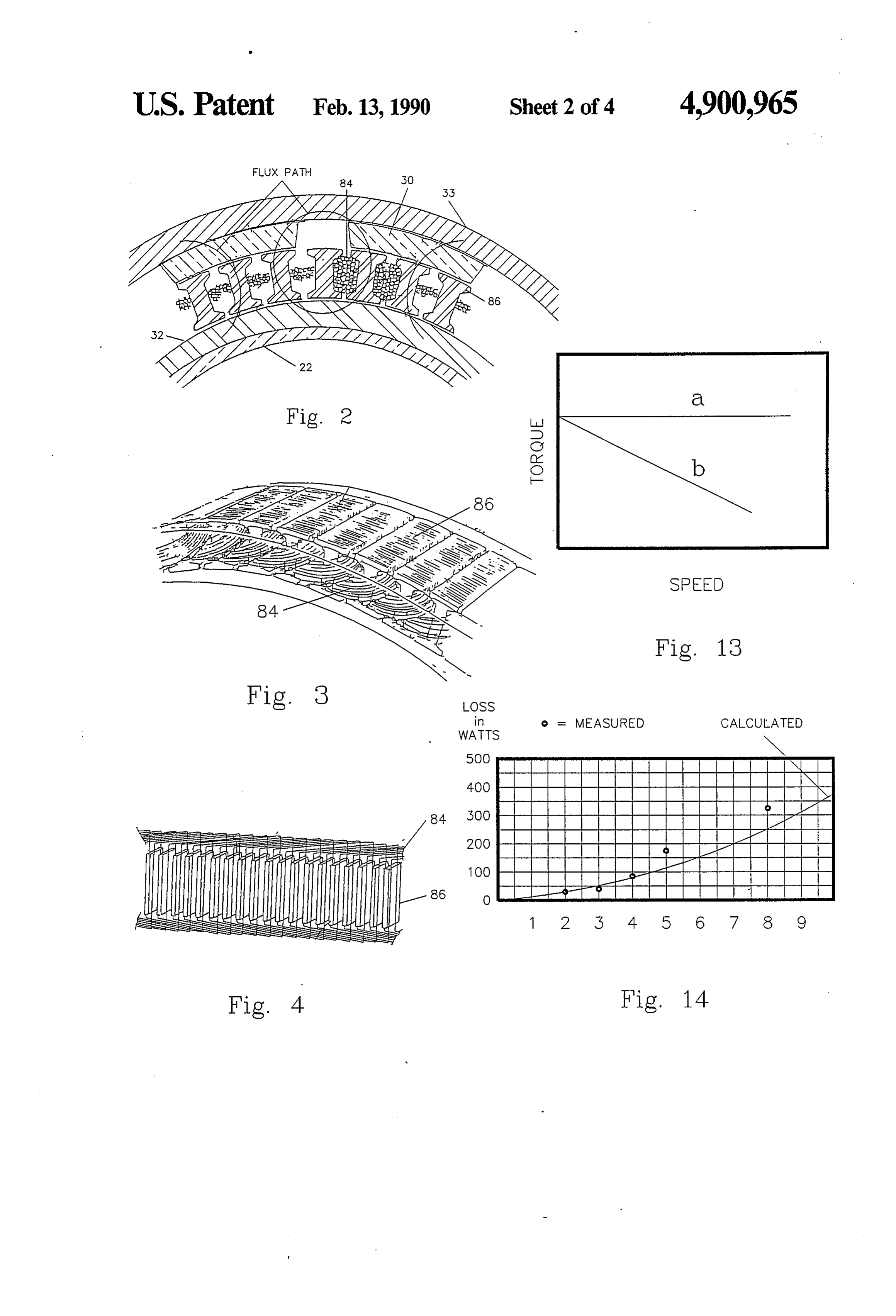
It is still another object of this invention to provide an FIG. 5 is a single lamination stamping of controlled improved electromotive device that is capable of con grain ferrous metal which, when laminated in mass, tinuous operation at high power densities in excess of form “I” beam stator bars.
one horsepower per pound. FIG. 6 is a single lamination stamping of controlled It is still another object of this invention to provide an grain ferrous metal which, when laminated in mass, improved electromotive device having an armature form a plurality of modi?ed “I” stator bars. assembly with dispersed conductors, different sections FIG. 7 is a partial isometric view of an armature of which have ?ux carrying elements positioned there showing the arrangement of the dispersed conductors between with the conductors and ?ux carrying ele and flux carrying elements of the electromotive device ments being formed and positioned in a manner so as to shown in FIG. 1.
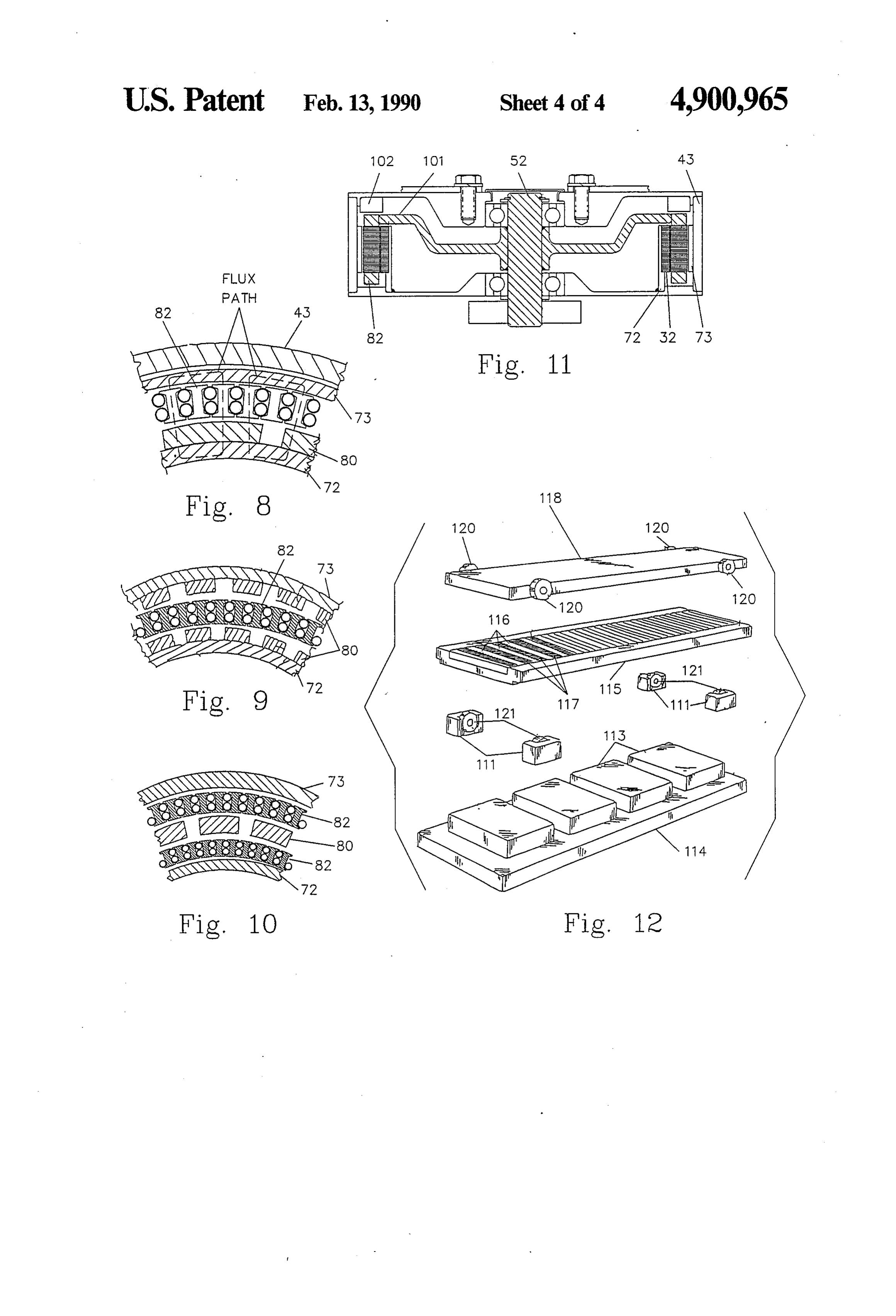
create low opposing induced currents. FIG. 8 is a partially cutaway view similar to that of It is still another object of this invention to provide an FIG. 2 but illustrating an alternate embodiment of the improved electromotive device having an optimum electromotive device of this invention. thickness armature assembly which represents a balance FIG. 9 is a partially cutaway view similar to that of among the effects of heat transfer to the cooling me 5 FIG. 2 but illustrating another alternate embodiment of dium, heat production from resistance heating and other the electromotive device of this invention. sources, and torque production. FIG. 10 is a partial cutaway view similar to that of The foregoing and other objectives will become ap FIG. 2 but illustrating still another alternate embodi parent to one skilled in the art as the description pro ment of the electromotive device of this invention. ceeds. This invention resides in the novel construction, FIG. 11 is a side sectional view of an alternate em combination, and arrangement of parts substantially as bodiment of the electromotive device as shown in FIG. described and illustrated in the speci?cation and draw 1, and illustrates the inductor ?xed to the shaft as may ings of this patent, and more particularly de?ned by the be convenient to a brush commutatedsystem. appended claims, it being understood that changes in FIG. 12 is an exploded isometric view of still another the precise embodiments of the herein disclosed inven alternate embodiment of the electromotive device of tion are meant to be included as within the scope of the this invention, and illustrates a ?at linear implementa claims. tion thereof.
FIG. 13 is a graph illustrating the relationship be
SUMMARY OF THE INVENTION tween torque and speed for a conventional electromo
This invention provides an improved electromotive tive device b and for the electromotive device of this device with a high power density per unit weight ef invention a.
fected by utilization of an armature assembly having a FIG. 14 is a graph illustrating tested eddy current, large diameter-thin cross section speculation ratio. This hysteresis and windage losses at different speeds of one results in low opposing induced currents, as well as low example of the electromotive device of this invention. eddy currents, to enable operation of the electromotive DESCRIPTION OF THE INVENTION device at high ef?ciency with high torque being main tainable during high speed operation. This invention provides a high power density (1 to 5 When the armature moves relative to a magnetic ?ux horsepower per pound) electromotive device incorpo producing assembly, eddy currents are established in 40 rating a large diameter-thin cross section speculation the electrically conductive portions of the armature and ratio. This is advantageous because for a given number these currents lead to heating and skin effects (collec of magnets or poles . . . the larger the diameter, the tively known as eddy current losses). However, these larger (circumferences) each can be. As diameter de currents also produce another effect not recognized by creases, the circumferential size of each magnet de the prior art. They are opposing induced currents 45 creases until it is virtually not seen or interacted with. which alter the magnetic flux pattern and act to reduce Conversely, given a ?xed size magnetic pole, as diame the torque with speed increase. This power conversion ter increases more magnetic poles can be utilized result reduction with speed increase is minimized in this in ing in working the copper-iron-magnets more times per vention by dispersing the conductors forming the wind revolution (producing more power). Therefore within ings. 50 limits, a reduction in diameter induces loss of power and efficiency per unit mass. In addition, through basic
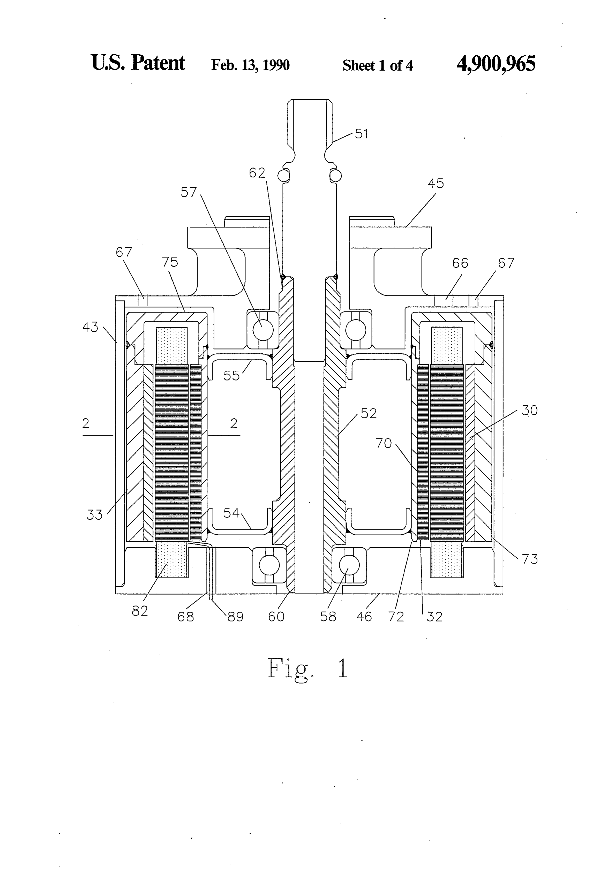
BRIEF DESCRIPTION OF THE DRAWINGS physics, torque is directly proportional to the effective The accompanying drawings illustrate complete em radius of the acting force (T=R>< F). Actually as you bodiments of the invention according to the best mode double the radius, you double the torque arm and dou so far devised for the practical application of the princi ble the amount of material producing torque, so power ples of this invention in which: and torque go up as the square of the radius. FIG. 1 is a side sectional view of a rotary implemen In a typical electric motor, torque falls off rapidly tation of the electromotive device of this invention. with increasing speed. This is primarily due to “oppos FIG. 2 is a sectional view taken through lines 2-2 of ing induced currents” or “eddy current losses” in the FIG. 1. copper conductors and armature bars. The losses associ FIG. 3 is a partial isometric view of an armature ated with the windings or copper are caused by; cross showing the arrangement of the dispersed conductors leakage between bars (made worse by radially long and flux carrying elements of the electromotive device bars), direct exposure of the copper to the magnetic shown in FIGS. 1 and 2. ?eld, and over saturation of the armature bars due to an FIG. 4 is a diagram illustrating a typical arrangement 65 excess amount of permanent magnet material. These of a two layer winding formed by the dispersed conduc losses are minimized by this invention. tors and illustrating the flux carrying elements posi Losses associated with bar-to-bar cross leakage are tioned between turns of the windings. reduced by designing the electromotive device of this
Page 8
invention so that it incorporates radially short armature The invention can be used as brush-commutated bars. motor or brushless, both in radial and linear con?gura _Losses induced by the copper being directly exposed tions. It can be used as a dc generator or an ac alterna to the magnetic ?eld is solved by the presient invention tor. The ultimate use depending on whether an electri by an I-shaped armature bar acting as a shield to the cal signal is conveyed to the armature to create a force, magnetic ?eld. causing movement of the magnetic flux producing Finally, losses caused by over saturation of the arma structure relative to the armature, or whether the mag ture bars is solved by reducing the amount of permanent netic ?ux producing structure is moved relative to the magnet material such that the bars just “approach” armature. -
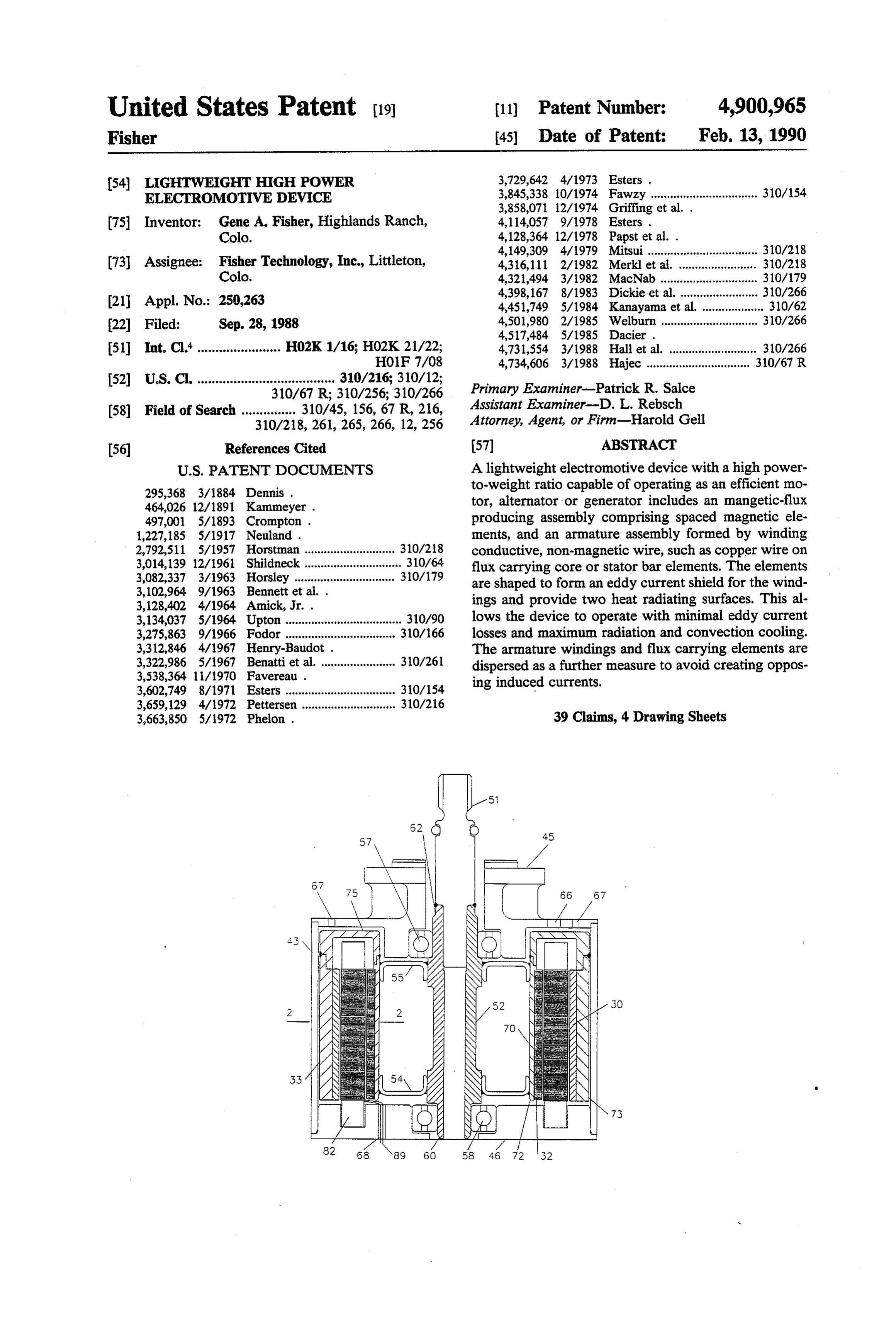
saturation. This is accomplished empirically as ex An exemplary embodiment of the electromotive de plained later. vice is illustrated in FIG. 1. This embodiment includes These three factors allow for much heavier wire to be an outer cylindrical housing 43 which is completed by utilized without fear of eddy current losses (cross-sec front 45 and rear end plates 46 secured at opposite ends tional area of wire approximately eight times that of of the cylindrical housing.
prior designs). The heavier gage wire provides two A shaft 51 includes a central portion 52 extending signi?cant functions; it signi?cantly reduces resistance through the cylindrical housing. The shaft is mounted in heating due to its cross-sectional area increase and it the end plates 45 and 46, respectively, by means of allows more conductor (copper) per available space. bearings 57 and 58 so that the central portion of the These two functions enable increased ef?ciency and shaft is coaxially positioned with respect to the cylindri cal housing. The reduced diameter rear portion 60 of increased power output respectively. In addition, the the shaft is mounted in bearing 58 and the front portion armature bars themselves are constructed as a lamina tion of several individual thin stampings, each insulated 62 of the shaft extends through the front bearing 57 and end plate 45.
one from the other. The insulation is a silicon oxide by The end plates, 45 and/or 46 may include air intake product produced during the annealing process. Be 25 and exhaust apertures 66 and 67. These apertures allow cause sheet metal stampings are utilized, the material cooling air to flow through the housing. In addition, an grain direction can be and is controlled in the radial aperture 68 is positioned to allow armature conductor direction thereby insuring a maximum flux carrying connections through end plate 46. In some environ capability (see FIG. 6). ments, the device cannot operate in a gas (air) medium, The controllable dispersion characteristics achieved 30 so liquid coolant, such as oil, is used. In such cases, the via thin lamination grain control provides much better housing is sealed to retain the liquid. performance than the powdered iron 3-d dispersion The rotor 70 has a double shell con?guration pro solid bars in the co-pending application previously ref vided by inner and outer spaced cylinders 72 and 73 erenced. The I-shaped lamination assembly (armature which extend normally from the ring connection por bar) lends itself to conventional automatic winding tion 75. The inner cylinder 72 is secured to the shaft techniques when a specialholding ?xture is utilized. center section 62 by a pair of hubs 54 and 55 to hold the The losses associated with the windings or copper double shell coaxially inside the cylindrical housing 43. caused by over-saturation of inductor bars due to an FIG. 2 is a portion of a cross~sectional view taken excess of permanent magnet material is addressed in the along lines 2-2 of FIG. 1. It more clearly illustrates present invention by designing the proper amount of 40 that the inner cylinder 72 of rotor 70 includes a mag permanent magnet material to “approach”- the satura netic ?ux return path in the form of a shell, 32, which is tion level of the armature bars. This is accomplished by preferably a lamination of rings of silicon iron or some empirical methodology to optimize the combination of other magnetically permeable, low hysteresis loss mag copper, iron, and permanent magnet materials to netic material supported by the cylindrical section 72 achieve optimum power density and optimum ef? 45 extending from the hubs 54 and 55. The cylinders 72 ciency through “saturation approaching”. Saturation or and 73 and connecting ring 75 are formed of any suit over-saturation is not necessary and is a serious detri able material, including iron. ment to good performance. In the empirical method, a The outer cylinder 73 comprises a magnetic flux very sensitive dynamometer is used to measure and plot return path, 33, which may be solid iron or some other losses as a function of ?eld. When copper eddy currents permeable, low hysteresis loss magnetic material and a were gone, the ?ux was not reduced anymore. Based on plurality of magnetic ?eld generator, such as magnets the developed data, the ?ux conducting bars are fabri 30, are mounted on the inner surface of return path 33. cated from a metal alloy having an iron content which In the exemplary embodiment, the magnets 30 are per creates a ?ux carrying ability approximately equal to manent magnets preferably formed of neodymium the flux saturation point as determined by the electrical boron ferrite (NdFeB), but they may be formed of bar properties of the design. ium ferrite ceramic (BaFe Ceramic), samarium cobalt The preferred embodiments of the invention use a (SmCo), or the like. Permanent magnets are used in the hollow cross-sectional arrangement which lends itself illustrated exemplary embodiment but they could be to multiple concentric elements or multiple-motors replaced with electromagnets. within-a-motor. These could be operated concurrently 60 Returning to FIG. 1, the stator inductor 82 is ?xed to maximize power density per available space, or indi with respect to housing 43. It is mounted on the rear end vidually in a staged manner (like shifting gears in a plate 46 so that the rotor 70 rotates around the common transmission). axis of the stator 82 and the housing 43. The stator 82 is The cross-sectional arrangement features two radiat a stationary cylindrical shell encompassed by the inner ing and convecting surfaces for rejecting heat from the 65 and outer cylinders 72 and 73 of the rotor. armature (conventional designs have one). Thus the The stator 82 includes electrical conductors 84 of motor can be driven at higher power levels for longer FIGS. 2 and 3 which are randomly dispersed between durations without overheating. stator bars 86. Dispersed conductors 84 are preferably a
Page 9
bundle of relatively large (for an electromotive device) plained and illustrated, cylindrical sections 72 and 73 diameter insulated copper wires wound into a linking provide support for the inner and outer magnetic flux pattern, with the opposite ends of the wire bundles return paths. Typical ?ux paths have been illustrated in connected to connectors 89 which extend through aper FIG. 2. As shown, these ?ux paths are loops, each of ture 68 in end plate 46 of FIG. 1. The use of dispersed, which penetrates the inductor or stator, twice passing large diameter windings enables the resultant electro through the flux carrying members 86. The flux carry motive device to achieve a high power-to-weight ratio ing members are dimensioned to create a thick induc because (1) the dispersed windings minimize eddy cur tion to maintain a high flux density which is essential to rents within the coils and (2) the large diameter wire high torque. Thus, as illustrated in FIG. 7, the dimen reduces the number of ?eld generating elements for a sion of the ?ux conducting bars 82 along the axis paral given power factor which also reduces eddy currents lel to the primary ?ux path through the bars is short within the coils. , relative to the longitudinal axis of the bars which paral Conductors 84 are formed into a bundle throughout lels the major axis of the electric windings 84 disposed the armature, with each turn of the wire windings hav about the bars for generating an electromagnetic ?eld. ing a ?ux carrying element or stator bar 86 therebe 15 As indicated in FIG. 8, the electromotive device may tween. A typical winding is schematically illustrated in be con?gured with magnets 80 on the outer surface of FIG. 4. the inner cylindrical section 72 rather than on the inner The ?ux carrying elements, stator bars 86, are prefer surface of the outer cylindrical section 73. In FIG. 9, ably a lamination of a plurality of silicon iron sheets. the electromotive device is con?gured with the mag FIG. 5 illustrates the con?guration of a single layer or nets 80 on both inner and outer sections 72 and 73. sheet of a laminated stator bar. The extensions 34 at the In FIG. 10, two cylindrical stators 82 encompass both four corners give the bar an “I” beam cross sectional sides of the magnets 80. In addition, while not speci? con?guration and provide increased surface area for cally shown, it is also to be realized that the electromo cooling, as well as flux shielding for the windings. tive device could be con?gured by placing additional These two advantages over the prior art are further 25 layers of stator-rotor elements radially inwardly and/ or features which enable the resultant electromotive de outwardly of that shown in the ?gures. vice to achieve a high power-to=weight ratio. Shielding The electromotive device of this invention thus in the electromotive windings from the magnetic ?elds cludes a magnetic flux producing assembly (having at within the motor minimizes eddy currents within the least one pair of poles which can be embodied by using coils. This and the increased cooling heat exchange 30 permanent magnets or electromagnets), and an inductor surface allows higher current ?ow which increases ?eld assembly (which intercepts the magnetic ?ux produced strength without increasing eddy currents in the wind by the magnetic flux producing assembly and has an mgs. alternating structure of conductive windings and flux The use of stampings such as illustrated in FIG. 5 carrying elements. A winding can be used as the princi allow the grain direction within the metal forming the 35 pal component of the inductor with the winding con bar to be controlled. Thus a bar may be produced with sisting of bundles of separate dispersed conductors. The a grain direction as illustrated in FIG. 5 wherein the use of dispersed conductors of large diameter wire per grain direction is parallel to the primary flux path mit high speed rotation of the rotor when used in con through the stator bar. This reduces heat generation junction with winding flux shielding, ?ux carrying ele because of the reduced level of resistance to magnetic ments.
flux. A random grain pattern provides maximum resis In the case of conductors of large cross section or tance which leads to maximum heat generation and a conductive flux carrying elements of large cross sec uniform grain pattern reduces resistance and its resul tion, as used at least in some prior known devices, as the tant heat. A grain pattern following the direction of ?ux frequency of the magnetic ?eld reversal increases, the resistance and heating. Thus a controlled 45 magnitude of the induced currents in the bars increases, grain inductor bar construction allows higher ?ux den and the induced currents react with the magnetic ?eld sities without increased heating. This increases the effi to create a resisting torque which opposes the increase ciency of the device and aids in reaching the stated of rotational speed. Thus, known shell type devices are objectives of the invention. inherently limited to low speed by the reaction torque, FIG. 6 illustrates an alternate shape for each layer of 50 and cannot be rotated at high speed and are therefore the laminated induction core or stator bar. In this em not suitable, for example, for use as traction motors in bodiment, all of the bars share a common central section most practical applications. However, by shielding the which simpli?es stamping, laminating and assembly. windings from the generated magnetic ?ux and isolat When used as a motor at constant current, the torque ing the flux created within the windings, induced cur output of this invention can be maintained nearly con 55 rents are limited and the forgoing impediments to high stant even with increases in rotor speed, as illustrated in speed/high-torque operation are eliminated. FIG. 13 by line a. This is unlike prior art devices When used as a motor, a means to displace (i.e., ro wherein torque drops off rapidly with increased speed, tate) the magnetic ?eld relative to the armature at high as indicated in FIG. 13 by line b. The combination of speed must be provided so that electric power can be high torque and high speed, made possible in the elec converted into mechanical power in a manner similar to tromotive device of this invention, results in a high that used by known motors. This can be accomplished power-to-weight ratio. by connecting connectors 89 of the armature 82 in FIG. The stator 82 (formed by the dispersed conductors 84 1 to a current source.
and ?ux carrying members 86) is closely spaced with When used as an alternator or generator, an actuator respect to magnets 80 positioned about the inner surface 65 rotates shaft 51 which rotates rotor 70 to induce a volt of the cylindrical ?ux return path 33, and also closely age on conductors 84 and thereby generate an electrical spaced with respect to the laminated cylindrical ?ux current flow from conductors 84 to a load via connec return path 32, see FIGS. 2 and 7. As previously ex tor 89. '
Page 10
While not speci?cally shown, it is to be understood While preferred embodiments of this invention have that the inductor includes necessary electric commuta been illustrated and described, variations and modi?ca tion devices, including those devices wherein commuta tions may be apparent to those skilled in the art. There tion is performed electronically (as in a brushless DC fore, I do not wish to be limited thereto and ask that the motor, for example), as well as those devices which scope and breadth of this invention be determined from employ recti?ers instead of commutation (as is often the claims which follow, rather than the above descrip used in power generating applications). A hall device, tion.
21 of FIG. 7, may be used in conjunction with a mag What I claim is:
netic ring 22 to sense inductor bar or pole piece passing 1. An electromotive device, comprising: to produce the required timing data. an inductor including a plurality of magnetic ?ux FIG. 11 illustrates an embodiment of the electromo conducting bars and electric windings disposed tive device of this invention in which the inductor 82 about said bars for generating an electromagnetic becomes an armature. It is connected to shaft 52 by ?eld;
mounting disk 101, and inner and outer cylinders 72 and said electric windings comprising electrical conduc 73 are ?xed to the housing 43. In this embodiment, the 15 tors randomly dispersed between said flux con inductor becomes the rotor with electric power being ducting bars;
communicated to it by means of brushes or slip rings said bars incorporating a geometry which shields said 102 (with brushes being utilized in the case of a DC windings from the magnetic ?elds within the elec machine, and slip rings beinq utilized in the case of an tromotive device;
a magnetic ?eld generator positioned adjacent to one
AC machine). The embodiment shown in FIG. 11 is preferred for some applications, particularly in the case side of said inductor;
a ?rst flux return path on the side of said magnetic of a DC commutated machine.
This invention has a signi?cant advantage over a ?eld generator opposite said inductor; and a second ?ux return path on the side of said inductor conventional motor by utilization of a minimum amount 25 opposite said magnetic ?eld generator. of iron which undergoes ?ux reversal. That is, only the 2. An electromotive device as de?ned in claim 1, iron in the ?ux carrying elements in the armature is wherein said ?ux conducting bars comprise a lamina subject to the reversing flux as each pole is passed, and tion of flux conducting sheets.
thus low hysteresis losses are experienced. In addition, 3. An electromotive device comprising: the effects of flux leakage are reduced so that all of the 30 an inductor including a plurality of magnetic flux armature windings experience the total ?ux change and conducting bars comprising a lamination of ?ux thus are equally useful at producing torque. conducting sheets and electric windings disposed This invention has signi?cant heat transfer advan about said bars for generating an electromagnetic tages through the use of “I” beam shaped stator bars, ?eld;
see FIG. 5. They make it possible to provide cooling to said electric windings disposed about said bars for both the inner and outer surfaces of the inductor. For generating an electromagnetic ?eld comprising this reason, the superior high power to weight ratio is electrical conductors randomly dispersed between further enhanced. said flux conducting bars; By the principles of heat transfer, heat buildup in an said bars incorporating a geometry which shields said inductor, with constant surfaces temperature and uni windings from the magnetic fields within the elec form internal heating per unit volume, depends on the tromotive device;
square of its thickness. For example, compare an “I” said flux conducting sheets are fabricated from silicon beam armature 0.25 inches thick (as is possible in this iron and insulated from each other by a coating of invention) to a solid rotor, ?ve inches in diameter (as is silicon oxide;
common in known devices). The heat buildup in such a magnetic ?eld generator positioned adjacent to one known devices is 400 times as great as experienced by side of said inductor;
this invention. a ?rst ?ux return path on the side of said magnetic The electromotive device of this invention can be ?eld generator opposite said inductor; and produced in several topological variations of the basic a second ?ux return path on the side of said inductor design. In addition to the rotating cylindrical shell con 50 opposite said magnetic ?eld generator. ?guration, by changing the orientation of the magnets 4. An electromotive device as de?ned in claim 2, and the windings, the motor can be made to produce a wherein said flux conducting sheets are fabricated with linear motion. Other variations (not shown) include a material grain direction parallel to the primary flux pancake and conical con?gurations. path through said ?ux conducting bars. FIG. 12 illustrates a linear reciprocating implementa 5. An electromotive device as de?ned in claim 1, tion of the electromotive device of this invention in comprising: means for reducing heat generation within which the structure is ?at. As shown, magnets 113 are said electromotive device, said means including said mounted on ?at lower return plate 114. Inductor 115 is flux conducting bars fabricated with a material grain provided with dispersed conductors 116 and flux carry direction parallel to the primary ?ux path through said ing elements 117 in the same manner as described here 60 ?ux conducting bars.
inabove with respect to the other embodiments illus 6. An electromotive device as de?ned in claim 1, trated except that the inductor is essentially ?at rather wherein said ?ux conducting bars are fabricated from a than cylindrical. An upper return plate 118 is also pro metal alloy having an iron content which creates a ?ux vided, and inductor 115 is movable linearly with respect carrying ability approximately equal to the flux satura to, and between, lower and upper plates 114 and 118 by 65 tion point as determined by the electrical properties of means of rollers 120 mounted on the edges of upper the design of said electromotive device. plate 118 and rollers 121 mounted in roller mounting 7. An electromotive device as de?ned in claim 1, boxes 111 (carried by lower plate 114). wherein the dimension of said flux conducting bars
Page 11
along the axis parallel to the primary flux path through insulated from each other by a coating of silicon said ?ux conducting bars is short relative to the longitu oxide and fabricated with a material grain direction dinal axis of said bars which parallels the major axis of parallel to the primary ?ux path through said flux said electric windings disposed about said bars for gen conducting bars from a silicon iron metal alloy erating an electromagnetic ?eld. having a ?ux carrying ability approximately equal 8. An electromotive device as de?ned in claim 3, to the flux saturation point as determined by the wherein said geometry includes extensions at the longi electrical properties of the design of said electro tudinal edges for increasing the heat exchange surface motive device.
of the inductor in addition to providing said magnetic 23. An electromotive device, comprising: shielding. a rotor including a plurality of magnetic flux con 9. An electromotive device as de?ned in claim 1, ducting bars and windings comprising electrical wherein said magnetic ?eld generator comprises perma conductors disposed about and randomly dispersed nent magnets. between said bars for generating an electromag 10. An electromotive device as de?ned in claim 1, netic ?eld;
wherein said ?rst ?ux return path is iron. said ?ux conducting bars incorporating a geometry 11. An electromotive device as de?ned in claim 1, which shields said windings from the magnetic wherein said second ?ux return path is fabricated from ?elds within the electromotive device, said flux the same alloy as said bars. conducting bars comprising a lamination of flux 12. An electromotive device as de?ned in claim 1, conducting sheets insulated from each other by a wherein said second ?ux return path is fabricated from coating of silicon oxide and fabricated with a mate the same material as said bars. rial grain direction parallel to the primary ?ux path 13. An electromotive device as de?ned in claim 1, through said flux conducting bars from a silicon wherein said inductor is a stator. iron metal alloy having a ?ux carrying ability ap 14. An electromotive device as de?ned in claim 1, proaching the ?ux saturation point as determined wherein said inductor is an armature. 25 by the electrical properties of the design of said 15. An electromotive device as de?ned in claim 1, electromotive device; i wherein said electromotive device is a linear motor. a plurality of permanent magnets positioned adjacent 16. An electromotive device as de?ned in claim 1, to one side of said rotor; wherein said electromotive device is a rotary motor. 21 solid iron ?ux return path on the side of said mag 17. An electromotive device as de?ned in claim 1, netic ?eld generator opposite said rotor; and wherein said electromotive device is a generator. a flux return path on the side of said inductor opposite 18. An electromotive device as de?ned in claim 1, said magnetic ?eld generator, said ?ux return path wherein said electromotive device is an alternator. comprising a lamination of flux conducting sheets 19. An electromotive device as de?ned in claim 1, insulated from each other by a coating of silicon wherein said geometry de?nes an “I”. 35 oxide and fabricated with a material grain direction 20. An electromotive device as de?ned in claim 1, parallel to the primary flux path through said ?ux wherein said electric windings comprise large diameter conducting bars from a silicon iron metal alloy conductors relative to the dimensions of said inductor. having a flux carrying ability approximately equal 21. An electromotive device as de?ned in claim 1, to the ?ux saturation point as determined by the wherein said geometry includes extensions at the longi electrical properties of the design of said electro tudinal edges for increasing the heat exchange surface motive device.
of the inductor in addition to providing said magnetic 24. An electromotive device as de?ned in claim 3, shielding. ' wherein said ?ux conducting sheets are fabricated with 22. An electromotive device, comprising: a material grain direction parallel to the primary ?ux a stator including a plurality of magnetic ?ux con path through said ?ux conducting bars. ducting bars and windings comprising electrical 25. An electromotive device as de?ned in claim 3, conductors disposed about and randomly dispersed comprising:
between said bars for generating an electromag— means for reducing heat generation within said elec netic ?eld; tromotive device, said means including said flux said ?ux conducting bars incorporating a geometry conducting bars fabricated with a material grain which shields said windings from the magnetic direction parallel to the primary ?ux path through ?elds within the electromotive device, said ?ux said flux conducting bars.
conducting bars comprising a lamination of flux 26. An electromotive device as de?ned in claim 3, conducting sheets insulated from each other by a wherein said flux conducting bars are fabricated from a coating of silicon oxide and fabricated with a mate metal alloy having an iron content which creates a ?ux rial grain direction parallel to the primary flux path carrying ability approximately equal to the ?ux satura through said flux conducting bars from a silicon tion point as determined by the electrical properties of iron metal alloy having a ?ux carrying ability ap the design of said electromotive device. proaching the ?ux saturation point as determined 27. An electromotive device as de?ned in claim 3, by the electrical properties of the design of said 60 wherein the dimension of said flux conducting bars electromotive device; along the axis parallel to the primary flux path through a plurality of permanent magnets positioned adjacent said ?ux conducting bars is short relative to the longitu to one side of said stator; dinal axis of said bars which parallels the major axis of a solid iron ?ux return path on the side of said mag said electric windings disposed about said bars for gen netic ?eld generator opposite said stator; and erating an electromagnetic ?eld.
a flux return path on the side of said inductor opposite 28. An electromotive device as de?ned in claim 3, said magnetic ?eld generator, said flux return path wherein said magnetic ?eld generator comprises penna comprising a lamination of flux conducting sheets nent magnets.
Page 12
29. An electrornotive device as de?ned in claim 3, 34. An electromotive device as de?ned in claim 3, wherein said ?rst ?ux return path is iron. wherein said electromotive device is a linear motor. 35. An electromotive device as de?ned in claim 3, 30. An electromotive device as de?ned in claim 3, wherein said electromotive device is a rotary motor. wherein said second ?ux return path is fabricated from 36. An electromotive device as de?ned in claim 3, the same alloy as said bars. wherein said electrornotive device is a generator. 31. An electromotive device as de?ned in claim 3, 37. An electromotive device as de?ned in claim 3, wherein said second ?ux returning path is fabricated wherein said electromotive device is an alternator. from the same material as said bars.
38. An electromotive device as de?ned in claim 3, 10 wherein said geometry de?nes an “I”.
32. An electrornotive device as de?ned in claim 3, 39. An electromotive device as de?ned in claim 3, wherein said inductor is a stator. wherein said electric windings comprise large diameter 33. An electromotive device as de?ned in claim 3, conductors relative to the dimensions of said inductor.
wherein said inductor is an armature.
Provenance
- Collection
- Cited prior art
- Original PDF
- patentimages.storage.googleapis.com →
- Filed
- 1988-09-28
- Pages
- 12
- Method
- pdftotext (the PDF's own text layer) + pdftoppm 300dpi page scans
- Source
- Google Patents bibliographic record
- Granted
- 1990-02-13
- Inventors
- Gene A. Fisher; Fisher Tech Inc
- Transcribed from
- patentimages.storage.googleapis.com →