patent · US4862581
Method of constructing a dynamoelectric machine
5 September 1989
Page 1 — bibliographic record
United States Patent (19) 11 Patent Number: 4,862,581 Royer (45. Date of Patent: Sep. 5, 1989 54 METHOD OF CONSTRUCTING A Attorney, Agent, or Firm-Polster, Polster and Lucchesi
DYNAMOELECTRIC MACHINE
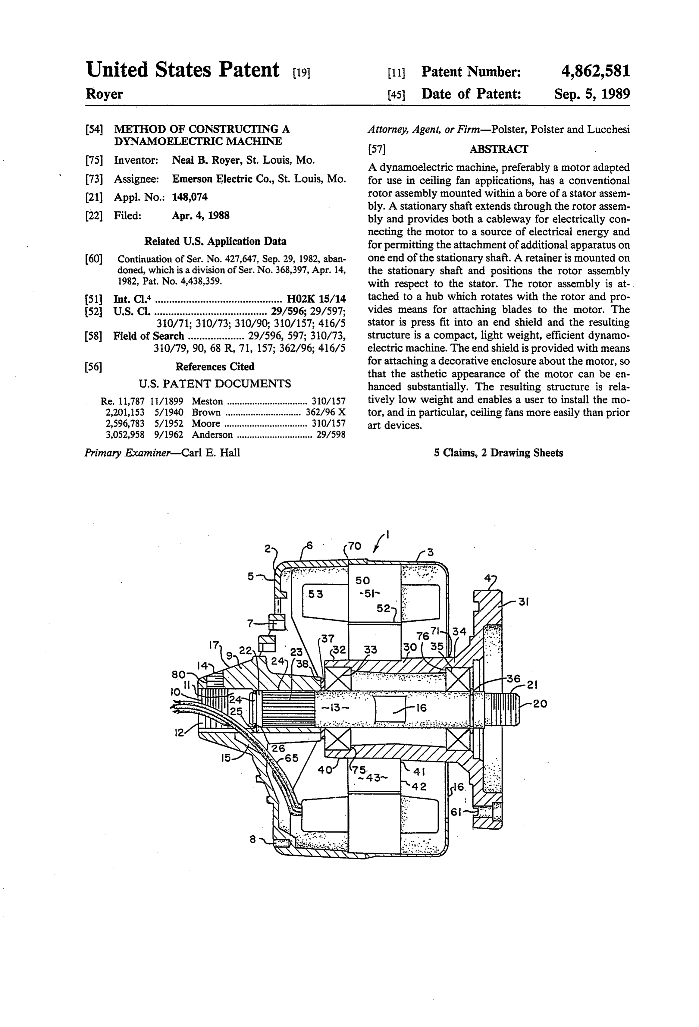
75 Inventor: Neal B. Royer, St. Louis, Mo. A dynamoelectric machine, preferably a motor adapted 73 Assignee: Emerson Electric Co., St. Louis, Mo. for use in ceiling fan applications, has a conventional (21) Appl. No.: 148,074 rotor assembly mounted within a bore of a stator assem bly. A stationary shaft extends through the rotor assem 22 Filed: Apr. 4, 1988 bly and provides both a cableway for electrically con necting the motor to a source of electrical energy and
Related U.S. Application Data for permitting the attachment of additional apparatus on 60 Continuation of Ser. No. 427,647, Sep. 29, 1982, aban one end of the stationary shaft. A retainer is mounted on doned, which is a division of Ser. No. 368,397, Apr. 14, the stationary shaft and positions the rotor assembly 1982, Pat. No. 4,438,359. with respect to the stator. The rotor assembly is at 51 Int. Cl." ............................................. HO2K 15/14 tached to a hub which rotates with the rotor and pro 52 U.S. C. ........................................ 29/596; 29/597; vides means for attaching blades to the motor. The 310/71; 310/73; 310/90; 310/157; 416/5 stator is press fit into an end shield and the resulting 58) Field of Search .................... 29/596,597; 310/73, structure is a compact, light weight, efficient dynamo 310/79,90, 68 R, 71, 157; 362/96; 416/5 electric machine. The endshield is provided with means (56) References Cited for attaching a decorative enclosure about the motor, so that the asthetic appearance of the motor can be en
Re. 11,787 / 1899 Meston ................................ 310/157 tively low weight and enables a user to install the no 2,201,153 5/1940 Brown .... ... 362/96 X tor, and in particular, ceiling fans more easily than prior 2,596,783 5/1952 Moore..... ... 310/157 art devices.
3,052,958 9/1962 Anderson .............................. 29/598
Primary Examiner-Carl E. Hall 5 Claims, 2 Drawing Sheets
Page 2
Drawing sheet — no readable text.
Page 3
Drawing sheet — no readable text.
Page 4
ceiling fan if the fan is to be installed in a home. That is
METHOD OF CONSTRUCTING A to say, the fan cannot be hung from a conventional DYNAMOELECTRIC MACHINE ceiling electrical box. Rather, additional braces are required along the ceiling rafters for safety purposes.
BACKGROUND OF THE INVENTION 5 Because of its weight, installation of such prior art ceil This invention relates to dynamoelectric machines ing fans by a single individual is nearly impossible. and in particular to AC induction motors. While the The invention disclosed hereinafter overcomes these invention is described with particular emphasis on the prior art deficiencies by providing a single motor struc use of the motor of this invention in ceiling fan applica 10 ture which can be used over a broad range of ceiling fan tions, those skilled in the art will recognize the wider designs and applications. In its industrial form, it may be applicability of the inventive concepts disclosed herein used without a decorative enclosure and provides a after. very light, easy to install product. In cases where as Ceiling fans, alone or in combination with other elec thetic appearance is important, the design enables the trical devices, for example, lights, light fixtures, or lumi 15 insertion of the motor in a decorative enclosure, so that naires have recently again become exceedingly popular. the motor per se is hidden. Even with such an enclo Most ceiling fan technology dates from the turn of the sure, however, the fan is light weight and can be in century, when such fans were used extensively. The stalled in a conventional manner without use of addi prior demise of the ceiling fan was coincident with the tional supports or braces. Installation by a single indi rise of the use of refrigerated air conditioning systems in vidual is not only possible but practical. The motor the 1940's and 50's. The relatively recent acceleration 20 includes a stationary center shaft which is used both for in energy costs, however, has caused the consumer to the attachment of additional components, and to pro look for alternate ways to "condition' air. In particular, vide a cableway for connection of those devices to a it has been found that a ceiling fan can be used during the heating season to return hot air from the ceilings of 25 source of electrical energy. One of the objects of this invention is to provide an relative high ceiling rooms toward the floor, providing improved motor design for ceiling fan applications. an air pattern which maintains a more constant tempera ture gradient in such rooms at a lower thermostat set tively light object
Another of this inention is to provide a rela weight motor design.
ting, with lower overall operating cost. Likewise, such Another object of this invention is to provide a motor air circulation during the cooling season permits a higher thermostat setting. Again, the improved temper 30 design adapted for ceiling fan applications which in ature gradient from floor to ceiling reduces overall cludes a stationary center shaft.
energy consumption resulting in lower operating costs. Another object of this invention is to provide a motor Consequently, the ceiling fan has regained its popularity for ceiling applications which can be used on a broad for a range of applications, from factories to resort range of those applications, including industrial and condominiums. 35 residential uses.
Historically, ceiling fan motors have been of two Another object of this invention is to provide a sim general types. The first, known in the art as an inside/- plified motor construction method of assembly. out motor, positioned the rotor externally of the stator Still another object of this invention is to provide a and permitted direct attachment of the fan blades to the simplified motor design which can be placed in an as rotor. Since the stator assembly was positioned inter thetically appealing enclosure simply and economically. nally of the rotor, a stationary shaft was inserted Other objects of this invention will be apparent to through the stator core. The stationary shaft made the those skilled in the art in light of the following descrip attachment of additional electrical components easy to tion and accompanying drawings.
accomplish. Unfortunately, inside/out motors are rela tively expensive to produce. They also weigh relatively 45 SUMMARY OF THE INVENTION large amounts in comparison to more conventional In accordance with this invention, generally stated, a motor designs. Consequently, their installation is com dynamoelectric machine, and in particular, a motor plicated and cannot easily be accomplished by a single design adaptable to ceiling fan applications is provided, individual. the preferred embodiment of which includes a motor More conventional stator/rotor motor designs also 50 having have been employed in ceiling fan applications. Con a stator aassembly. stationary center shaft mounted in the bore of ventional motors do not lend themselves to ceiling fan which is rotatable Awith rotor assembly is mounted on a hub applications as readily as inside/out motors in that they respect to the stationaryit.center The hub also is rotatable with do not provide an easy way to attach additional devices nection devices associated with itshaft. for The hub has con mounting a plural to the ceiling fan. In particular, the addition of a light or 55 ity of fan blades to the hub. The motor is constructed so a lighting fixture to the ceiling fan structure is difficult to accomplish with conventional stator/rotor designs that the various motor elements depend from a single end shield which in turn can be attached to a conven - because the rotor for the motor is located in the central bore of the stator assembly, and rotates during motor tional pipe extension or the like for mounting the ceiling operation. I am aware of motor designs of the conven fan in a particular application. A method for construct tional stator/rotor type in which a large sleeve bearing ing a motor is disclosed which employs a single end has been used in conjunction with a second stationary shield for attaching the motor elements. The end shield shaft. The stationary shaft facilitates attachment of the also has a connection system associated with it for per above-mentioned luminaires or other electrical devices. mitting the insertion of the motor in a decorative enclo However, the design and construction of such prior art 65 Sle.
motors have produced products having severe weight BRIEF DESCRIPTION OF THE DRAWINGS handicaps. For example, one prior art design with which I am familiar requires additional support for the In the drawings,
Page 5
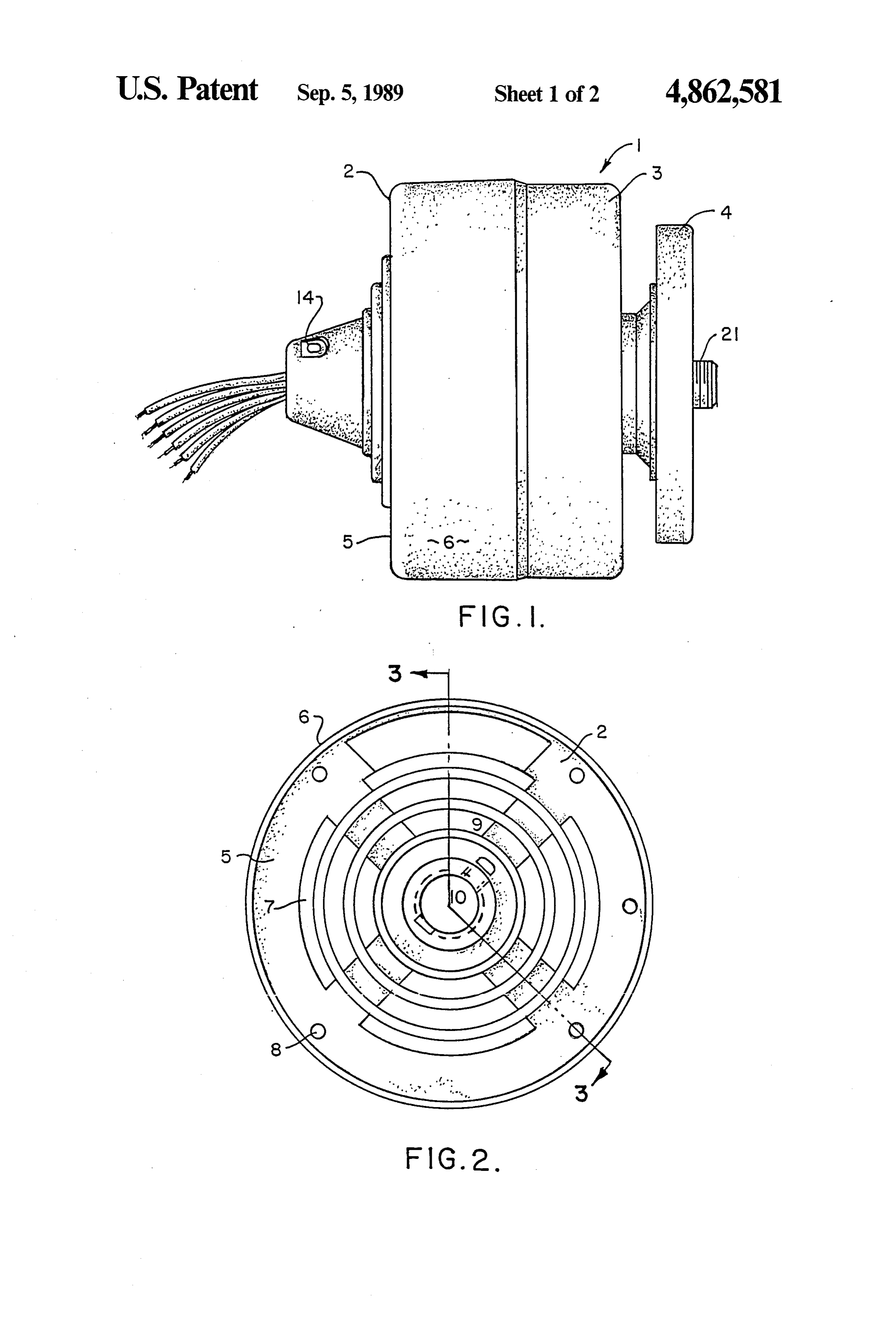
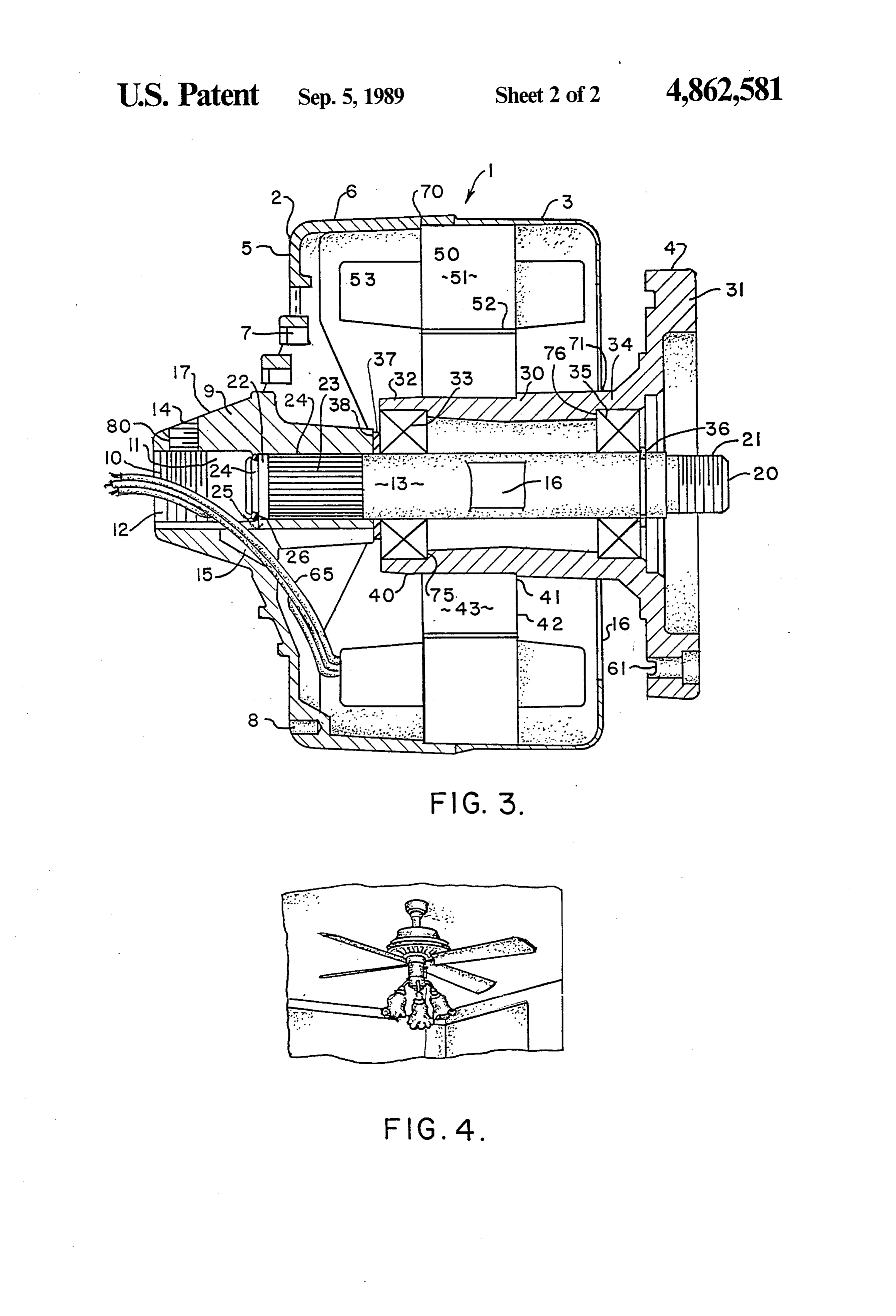
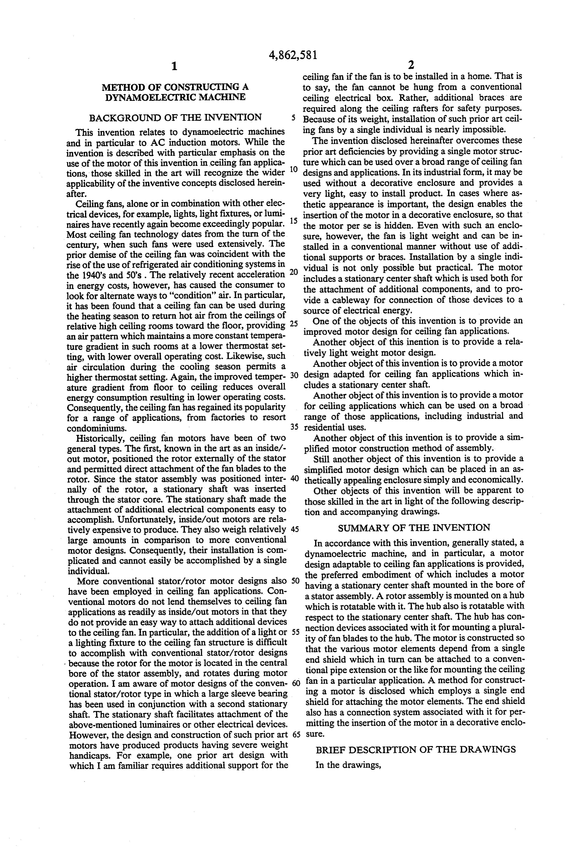
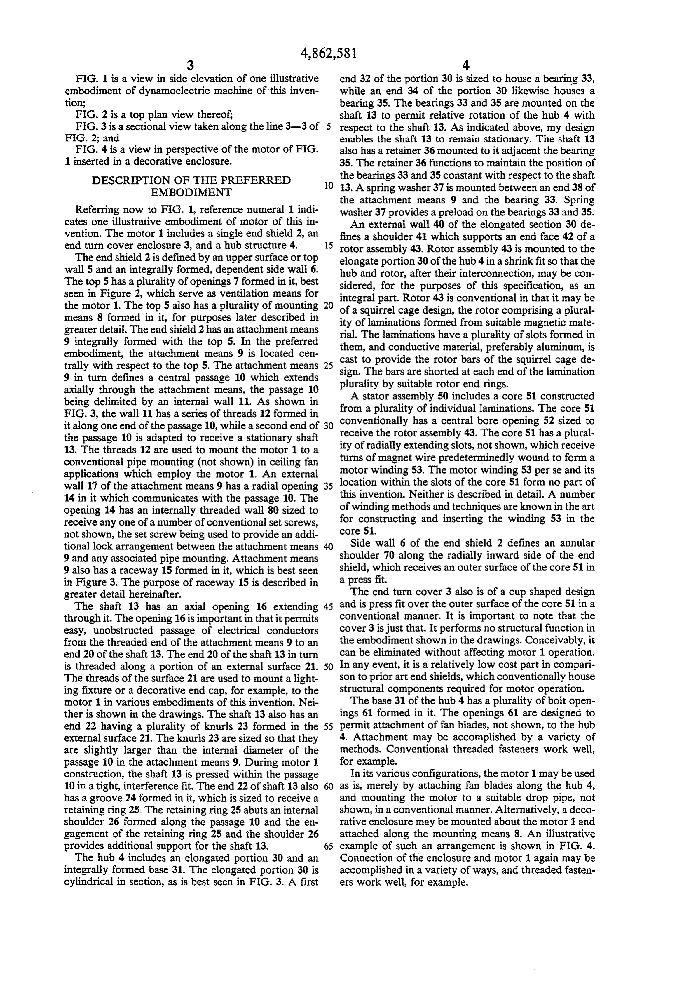
FIG. 1 is a view in side elevation of one illustrative end 32 of the portion 30 is sized to house a bearing 33, embodiment of dynamoelectric machine of this inven while an end 34 of the portion 30 likewise houses a tion; bearing 35. The bearings 33 and 35 are mounted on the FIG. 2 is a top plan view thereof; shaft 13 to permit relative rotation of the hub 4 with FIG. 3 is a sectional view taken along the line 3-3 of 5 respect to the shaft 13. As indicated above, my design FIG. 2; and enables the shaft 13 to remain stationary. The shaft 13 FIG. 4 is a view in perspective of the motor of FIG. also has a retainer 36 mounted to it adjacent the bearing 1 inserted in a decorative enclosure. 35. The retainer 36 functions to maintain the position of DESCRIPTION OF THE PREFERRED the bearings 33 and 35 constant with respect to the shaft 10 13. A spring washer 37 is mounted between an end 38 of
EMBODIMENT
the attachment means 9 and the bearing 33. Spring
Referring now to FIG. 1, reference numeral 1 indi washer 37 provides a preload on the bearings 33 and 35. cates one illustrative embodiment of motor of this in An external wall 40 of the elongated section 30 de vention. The motor 1 includes a single end shield 2, an fines a shoulder 41 which supports an end face 42 of a end turn cover enclosure 3, and a hub structure 4. 15 rotor assembly 43. Rotor assembly 43 is mounted to the The end shield 2 is defined by an upper surface or top elongate portion 30 of the hub 4 in a shrink fit so that the wall 5 and an integrally formed, dependent side wall 6. hub and rotor, after their interconnection, may be con The top 5 has a plurality of openings 7 formed in it, best sidered, for the purposes of this specification, as an seen in Figure 2, which serve as ventilation means for integral part. Rotor 43 is conventional in that it may be the motor 1. The top 5 also has a plurality of mounting 20 of a squirrel cage design, the rotor comprising a plural means 8 formed in it, for purposes later described in greater detail. The end shield 2 has an attachment means ity of laminations formed from suitable magnetic mate 9 integrally formed with the top 5. In the preferred them,The rial.
and laminations have a plurality of slots formed in conductive material, preferably aluminum, is embodiment, the attachment means 9 is located cen cast to provide trally with respect to the top 5. The attachment means 25 sign. The bars aretheshorted rotor bars of the squirrel cage de 9 in turn defines a central passage 10 which extends plurality by suitable rotor atendeach end of the lamination rings.
axially through the attachment means, the passage 10 A stator assembly 50 includes a core 51 constructed being delimited by an internal wall 11. As shown in from a plurality of individual laminations. The core 51 FIG. 3, the wall 11 has a series of threads 12 formed in it along one end of the passage 10, while a second end of 30 conventionally has a central bore opening 52 sized to the passage 10 is adapted to receive a stationary shaft receive the rotor assembly 43. The core 51 has a plural ity of radially extending slots, not shown, which receive 13. The threads 12 are used to mount the motor 1 to a conventional pipe mounting (not shown) in ceiling fan turns of magnet wire predeterminedly wound to form a applications which employ the motor 1. An external motor winding 53. The motor winding 53 perse and its wall 17 of the attachment means 9 has a radial opening 35 location within the slots of the core 51 form no part of this invention. Neither is described in detail. A number 14 in it which communicates with the passage 10. The opening 14 has an internally threaded wall 80 sized to of winding methods and techniques are known in the art receive any one of a number of conventional set screws, for constructing and inserting the winding 53 in the not shown, the set screw being used to provide an addi core Side
wall 6 of the end shield 2 defines an annular tional lock arrangement between the attachment means 40 9 and any associated pipe mounting. Attachment means shoulder 70 along the radially inward side of the end 9 also has a raceway 15 formed in it, which is best seen shield, which receives an outer surface of the core 51 in in Figure 3. The purpose of raceway 15 is described in a press fit.
greater detail hereinafter. The end turn cover 3 also is of a cup shaped design The shaft 13 has an axial opening 16 extending 45 and is press fit over the outer surface of the core 51 in a through it. The opening 16 is important in that it permits conventional manner. It is important to note that the easy, unobstructed passage of electrical conductors cover 3 is just that. It performs no structural function in from the threaded end of the attachment means 9 to an the embodiment shown in the drawings. Conceivably, it end 20 of the shaft 13. The end 20 of the shaft 13 in turn can be eliminated without affecting motor 1 operation. is threaded along a portion of an external surface 21. 50 In any event, it is a relatively low cost part in compari The threads of the surface 21 are used to mount a light son to prior art endshields, which conventionally house ing fixture or a decorative end cap, for example, to the structural components required for motor operation. motor 1 in various embodiments of this invention. Nei The base 31 of the hub 4 has a plurality of bolt open ther is shown in the drawings. The shaft 13 also has an ings 61 formed in it. The openings 61 are designed to end 22 having a plurality of knurls 23 formed in the 55 permit attachment of fan blades, not shown, to the hub external surface 21. The knurls 23 are sized so that they 4. Attachment may be accomplished by a variety of are slightly larger than the internal diameter of the methods. Conventional threaded fasteners work well, passage i0 in the attachment means 9. During motor 1. for example.
construction, the shaft 13 is pressed within the passage In its various configurations, the motor 1 may be used 10 in a tight, interference fit. The end 22 of shaft 13 also 60 as is, merely by attaching fan blades along the hub 4, has a groove 24 formed in it, which is sized to receive a and mounting the motor to a suitable drop pipe, not retaining ring 25. The retaining ring 25 abuts an internal shown, in a conventional manner. Alternatively, a deco shoulder 26 formed along the passage 10 and the en rative enclosure may be mounted about the motor 1 and gagement of the retaining ring 25 and the shoulder 26 attached along the mounting means 8. An illustrative provides additional support for the shaft 13. 65 example of such an arrangement is shown in FIG. 4. The hub 4 includes an elongated portion 30 and an Connection of the enclosure and notor 1 again may be integrally formed base 31. The elongated portion 30 is accomplished in a variety of ways, and threaded fasten cylindrical in section, as is best seen in FIG. 3. A first ers work well, for example.
Page 6
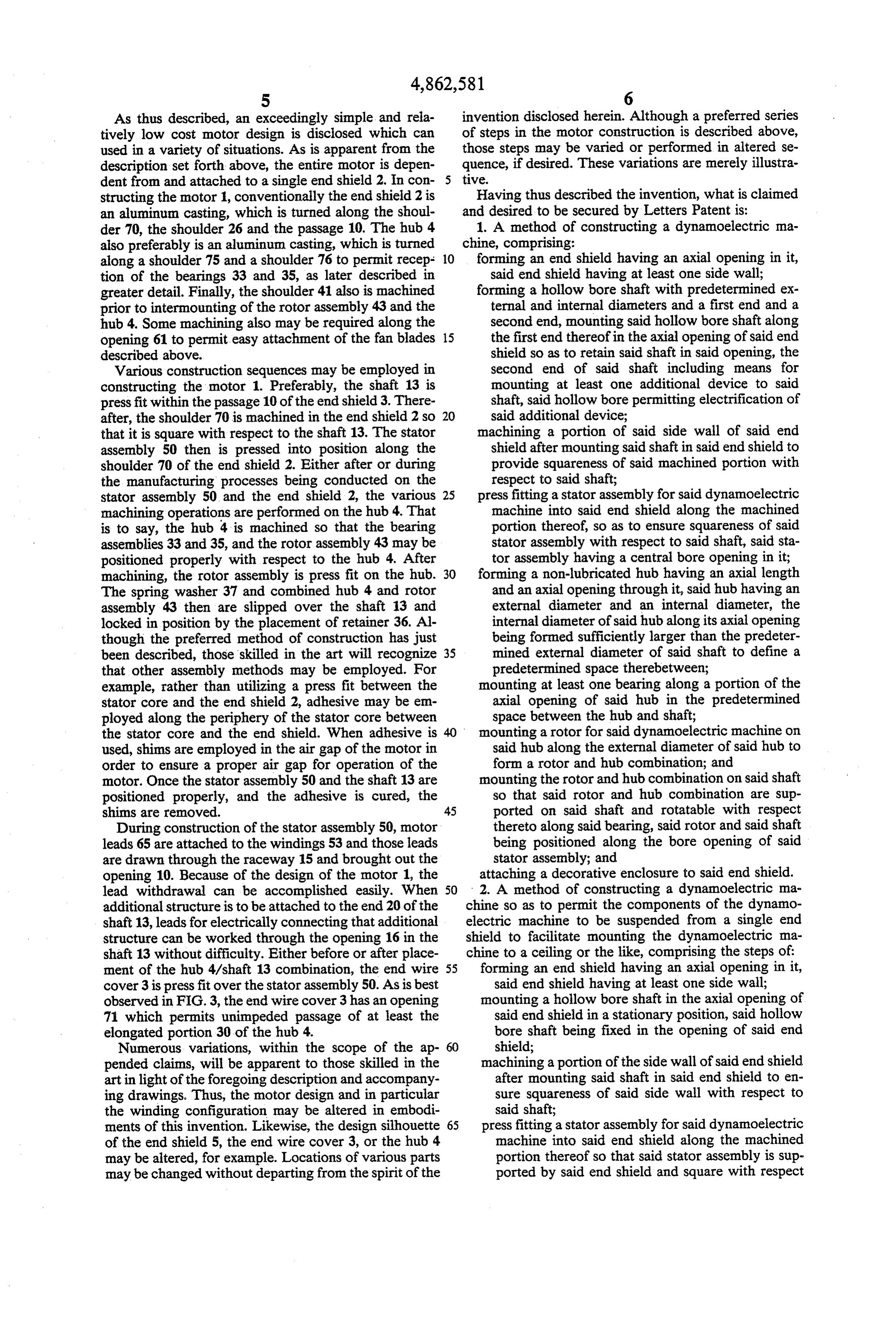
As thus described, an exceedingly simple, and rela invention disclosed herein. Although a preferred series tively low cost motor design is disclosed which can of steps in the motor construction is described above, used in a variety of situations. As is apparent from the those steps may be varied or performed in altered se description set forth above, the entire motor is depen quence, if desired. These variations are merely illustra dent from and attached to a single end shield 2. In con tive.
structing the motor 1, conventionally the end shield 2 is Having thus described the invention, what is claimed an aluminum casting, which is turned along the shoul and desired to be secured by Letters Patent is: der 70, the shoulder 26 and the passage 10. The hub 4 1. A method of constructing a dynamoelectric ma also preferably is an aluminum casting, which is turned chine, comprising:
along a shoulder 75 and a shoulder 76 to permit recep 10 forming an end shield having an axial opening in it, tion of the bearings 33 and 35, as later described in said end shield having at least one side wall; greater detail. Finally, the shoulder 41 also is machined forming a hollow bore shaft with predetermined ex prior to intermounting of the rotor assembly 43 and the ternal and internal diameters and a first end and a hub 4. Some machining also may be required along the second end, mounting said hollow bore shaft along opening 61 to permit easy attachment of the fan blades 15 the first end thereof in the axial opening of said end described above. shield so as to retain said shaft in said opening, the Various construction sequences may be employed in second end of said shaft including means for constructing the motor 1. Preferably, the shaft 13 is mounting at least one additional device to said press fit within the passage 10 of the endshield 3. There shaft, said hollow bore permitting electrification of after, the shoulder 70 is machined in the end shield 2 so 20 said additional device;
that it is square with respect to the shaft 13. The stator machining a portion of said side wall of said end assembly 50 then is pressed into position along the shield after mounting said shaft in said end shield to shoulder 70 of the end shield 2. Either after or during provide squareness of said machined portion with the manufacturing processes being conducted on the respect to said shaft;
stator assembly 50 and the end shield 2, the various 25 press fitting a stator assembly for said dynamoelectric machining operations are performed on the hub 4. That machine into said end shield along the machined is to say, the hub 4 is machined so that the bearing portion thereof, so as to ensure squareness of said assemblies 33 and 35, and the rotor assembly 43 may be stator assembly with respect to said shaft, said sta positioned properly with respect to the hub 4. After tor assembly having a central bore opening in it; machining, the rotor assembly is press fit on the hub. 30 forming a non-lubricated hub having an axial length The spring washer 37 and combined hub 4 and rotor and an axial opening through it, said hub having an assembly 43 then are slipped over the shaft 13 and external diameter and an internal diameter, the locked in position by the placement of retainer 36. Al internal diameter of said hub along its axial opening though the preferred method of construction has just being formed sufficiently larger than the predeter been described, those skilled in the art will recognize 35 mined external diameter of said shaft to define a that other assembly methods may be employed. For predetermined space therebetween; example, rather than utilizing a press fit between the mounting at least one bearing along a portion of the stator core and the end shield 2, adhesive may be em axial opening of said hub in the predetermined ployed along the periphery of the stator core between space between the hub and shaft; the stator core and the end shield. When adhesive is mounting a rotor for said dynamoelectric machine on used, shims are employed in the air gap of the motor in said hub along the external diameter of said hub to order to ensure a proper air gap for operation of the form a rotor and hub combination; and motor. Once the stator assembly 50 and the shaft 13 are mounting the rotor and hub combination on said shaft positioned properly, and the adhesive is cured, the so that said rotor and hub combination are sup shims are removed. 45 ported on said shaft and rotatable with respect During construction of the stator assembly 50, motor thereto along said bearing, said rotor and said shaft leads 65 are attached to the windings 53 and those leads being positioned along the bore opening of said are drawn through the raceway 15 and brought out the stator assembly; and opening 10. Because of the design of the motor 1, the attaching a decorative enclosure to said end shield. lead withdrawal can be accomplished easily. When 50 2. A method of constructing a dynamoelectric ma additional structure is to be attached to the end 20 of the chine so as to permit the components of the dynamo shaft 13, leads for electrically connecting that additional electric machine to be suspended from a single end structure can be worked through the opening 16 in the shield to facilitate mounting the dynamoelectric ma shaft 13 without difficulty. Either before or after place chine to a ceiling or the like, comprising the steps of: ment of the hub 4/shaft 13 combination, the end wire 55 forming an end shield having an axial opening in it, cover 3 is press fit over the stator assembly 50. As is best said end shield having at least one side wall; observed in FIG.3, the end wire cover 3 has an opening mounting a hollow bore shaft in the axial opening of 71 which permits unimpeded passage of at least the said end shield in a stationary position, said hollow elongated portion 30 of the hub 4. bore shaft being fixed in the opening of said end Numerous variations, within the scope of the ap shield;
pended claims, will be apparent to those skilled in the machining a portion of the side wall of said endshield art in light of the foregoing description and accompany after mounting said shaft in said end shield to en ing drawings. Thus, the motor design and in particular sure squareness of said side wall with respect to the winding configuration may be altered in embodi said shaft;
ments of this invention. Likewise, the design silhouette 65 press fitting a stator assembly for said dynamoelectric of the end shield 5, the end wire cover 3, or the hub 4 machine into said end shield along the machined may be altered, for example. Locations of various parts portion thereof so that said stator assembly is sup may be changed without departing from the spirit of the ported by said end shield and square with respect
Page 7
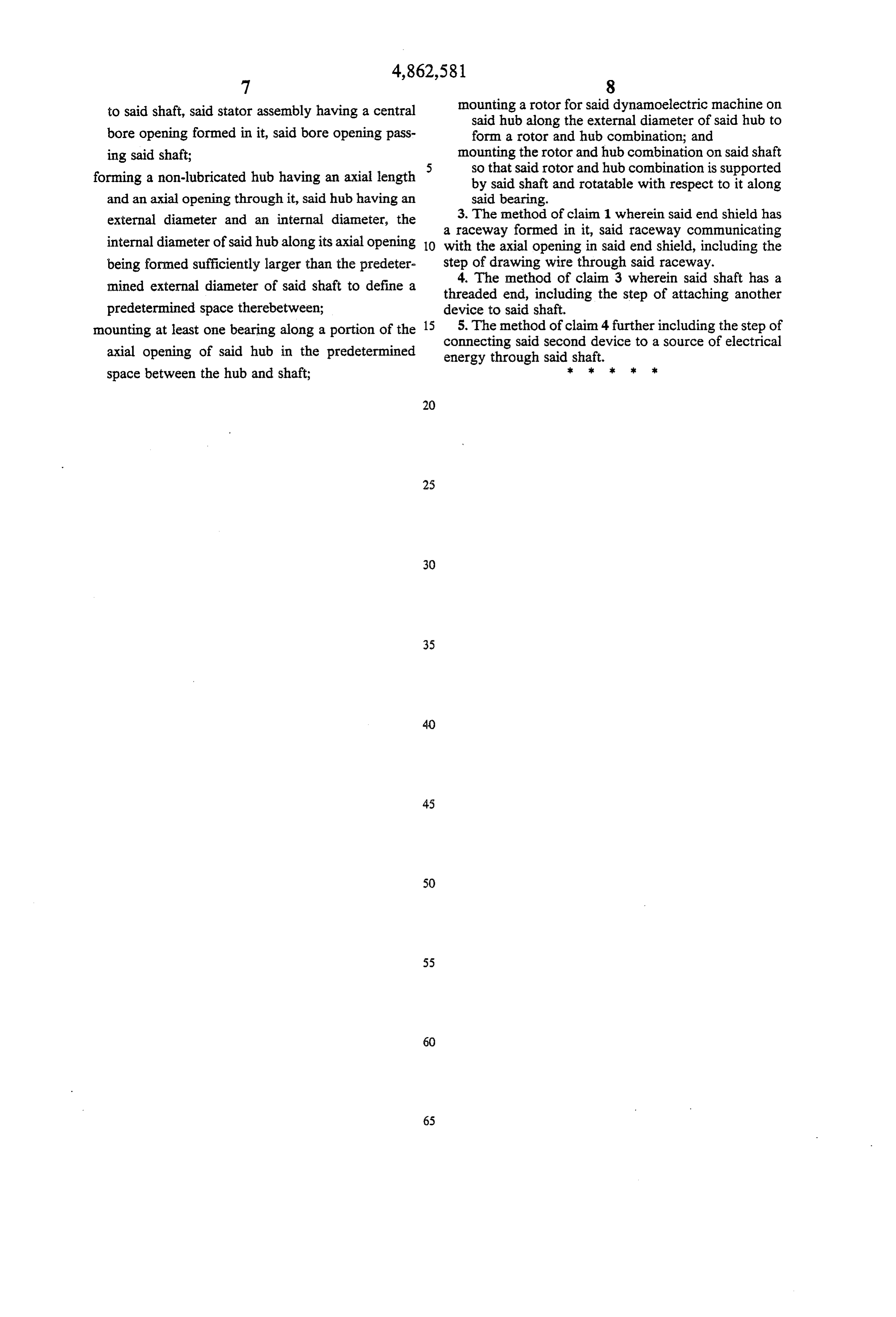
to said shaft, said stator assembly having a central mounting a rotor for said dynamoelectric machine on said hub along the external diameter of said hub to bore opening formed in it, said bore opening pass form a rotor and hub combination; and ing said shaft; mounting the rotor and hub combination on said shaft forming a non-lubricated hub having an axial length 5 so that said rotor and hub combination is supported by said shaft and rotatable with respect to it along and an axial opening through it, said hub having an said bearing.
external diameter and an internal diameter, the 3. The method of claim 1 wherein said end shield has a raceway formed in it, said raceway communicating internal diameter of said hub along its axial opening 10 with the axial opening in said end shield, including the being formed sufficiently larger than the predeter step of drawing wire through said raceway. mined external diameter of said shaft to define a 4. The method of claim 3 wherein said shaft has a threaded end, including the step of attaching another predetermined space therebetween; device to said shaft.
mounting at least one bearing along a portion of the 15 5. The method of claim 4 further including the step of connecting axial opening of said hub in the predetermined energy through said second device to a source of electrical said shaft.
space between the hub and shaft;
Page 8
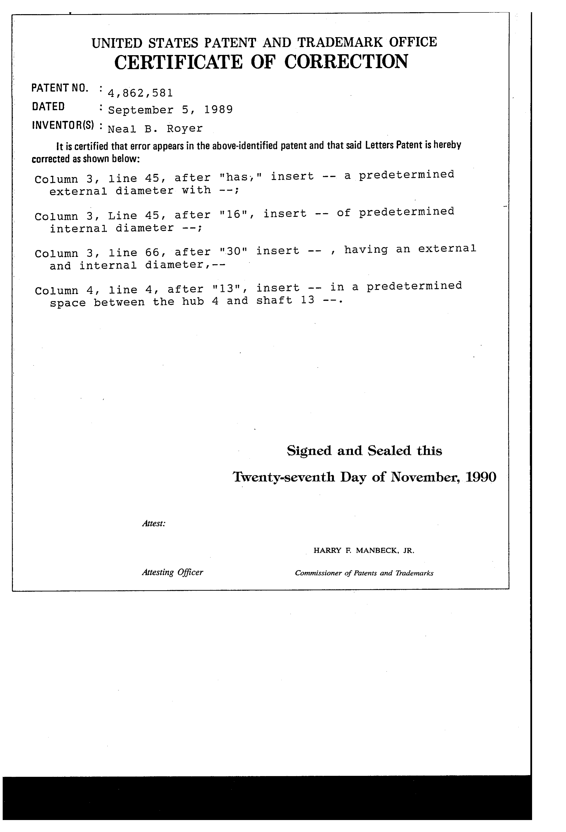
UNITED STATES PATENT AND TRADEMARK OFFICE
CERTIFICATE OF CORRECTION
INVENTOR(S) : Neal B. Royer it is certified that error appears in the above-identified patent and that said Letters Patent is hereby corrected as shown below:
column 3, line 45, after "has," insert -- a predetermined external diameter With -- ;
Collutin 3, Line 45, after "16", insert -- of predetermined internal diameter -- ;
Column 3, line 66, after "30" insert -- , having an external and internal diameter , -- column 4, line 4, after "13", insert -- in a predetermined space between the hub 4 and shaft 13 -- .
Signed and Sealed this
Twenty-seventh Day of November, 1990
HARRY F. MANBECK, JR.
Attesting Officer Commissioner of Patents and Trademarks
Provenance
- Collection
- Cited prior art
- Original PDF
- patentimages.storage.googleapis.com →
- Filed
- 1988-04-04
- Pages
- 8
- Method
- pdftotext (the PDF's own text layer) + pdftoppm 300dpi page scans
- Source
- Google Patents bibliographic record
- Granted
- 1989-09-05
- Inventors
- Neal B. Royer; Emerson Electric Co
- Transcribed from
- patentimages.storage.googleapis.com →