patent · US4850860
Radiant wall for heat exchangers, muffle kilns and similar equipment
25 July 1989
Page 1 — bibliographic record
United States Patent (19) (11) Patent Number: 4,850,860 Albonetti (45) Date of Patent: Jul. 25, 1989 54 RADIANT WALL FOR HEAT EXCHANGERS, 3,425,675 2/1969 Twine ................................. 432/209 MUFFLE KILNS AND SIMILAR 3,917,445 11/1975 Suva et al. .......................... 432/141 EQUIPMENT 4,222,987 9/1980 Keller .................................. 432/209 4,373,702 2/1983 Jayaraman et al. ... 432/175 (76) Inventor: Alberto Albonetti, no. 5/HVia 4,448,401 5/1984 Jalil et al. ........... ... 432/59 Venturi, Casinalbo-Modena, Italy 4,526,538 7/1985 Redell et al. ........................ 432/246 21 Appl. No.: 194,314 FOREIGN PATENT DOCUMENTS 22 Filed: May 16, 1988 1535098 12/1978 United Kingdom . (30) Foreign Application Priority Data Primary Examiner-Henry C. Yuen
Jun. 19, 1987 IT Italy ............................... 40.073 A/87 Attorney, Agent, or Firm-Fay, Sharpe, Beall, Fagan, Minnich & McKee 5ll Int. Cl. ........................... F27B 9/28; F27D 3/00 52 U.S. Cl. ...................................... 432/59; 432/175; (57) ABSTRACT 432/141; 432/206; 432/209 A radiant wall (6) for heat exchangers, muffle kilns and 58) Field of Search ............... 432/209, 206, 246, 236, similar equipment, consisting in a succession of rollers 432/175, 8, 59; 165/6, 10, 86 (11) suspended side by side in such a way as to create a (56) References Cited physical barrier for the separation of two environments
heat is brought about.
2,800,317 7/1957 Ipsen ............. ... 432/209 3,188,068 6/1965 Schmidt .............................. 432/206 7 Claims, 2 Drawing Sheets
Page 2
Drawing sheet — no readable text.
Page 3
Drawing sheet — no readable text.
Page 4
ronments containing means between which an exchange
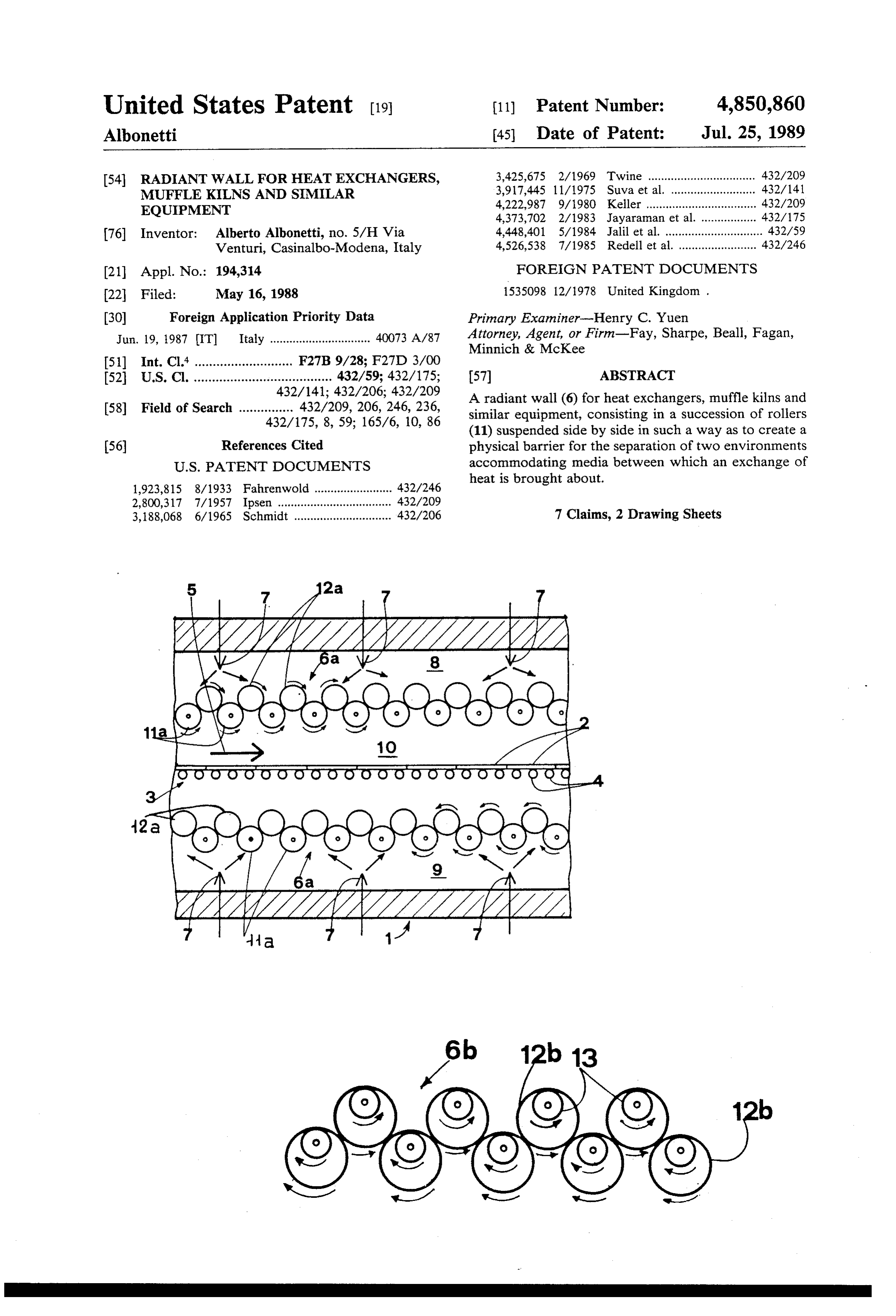
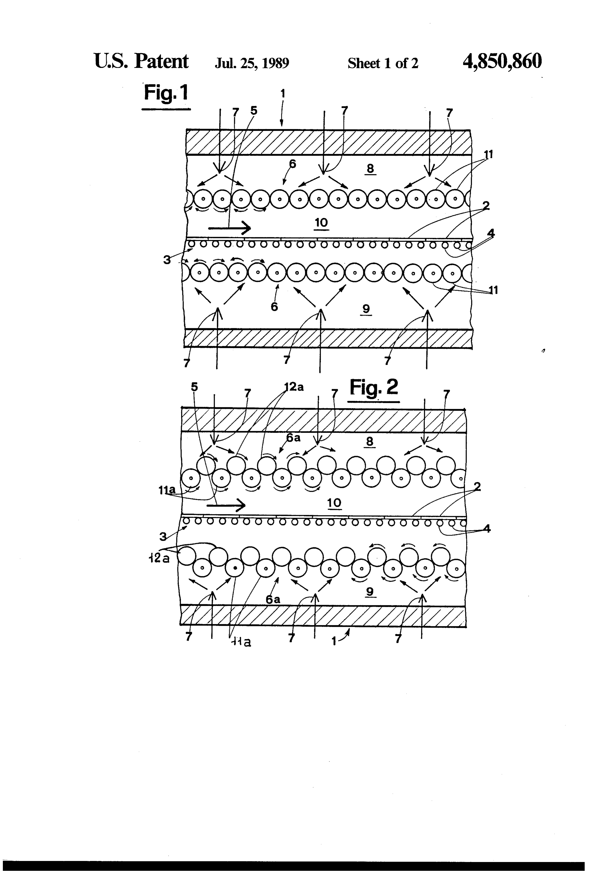
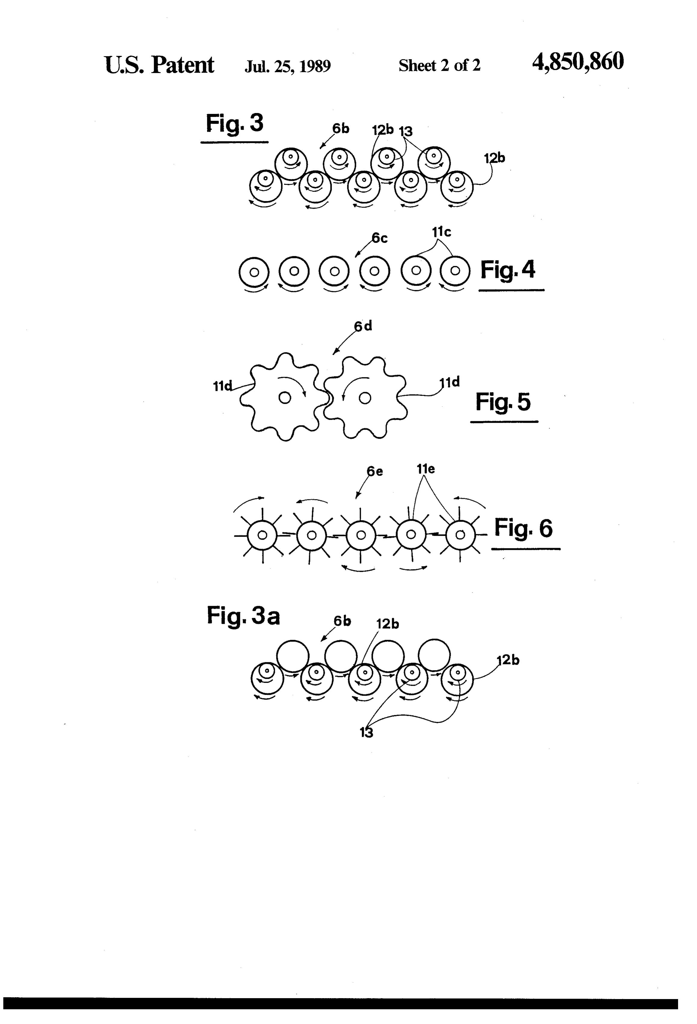
RADIANT WALL FOR HEAT EXCHANGERS, of thermal energy is brought about. MUFFLE KILNS AND SIMILAREQUIPMENT BRIEF DESCRIPTION OF THE DRAWINGS BACKGROUND OF THE INVENTION 5 The invention will now be described in detail, by way The present invention relates to a radiant wall, in of example, with the aid of the accompanying drawings, in which:
particular for heat exchangers, muffle kilns and similar FIG. 1 is a schematic representation showing part of equipment. a kiln for the firing of ceramic tiles, viewed in longitudi Such a wall lends itself to use in numerous fields of to nal section through the median vertical plane and em application, and more especially, wherever there may bodied according to the invention; be a requirement for treatment processes that involve an FIG. 2 is a schematic representation showing part of exchange of heat. A typical instance is that of a kiln, in a kiln for the firing of ceramic tiles, viewed in longitudi which thermal energy produced by the combustion of nal section through the median vertical plane and illus solid or liquid fuels, or gas, is exploited for the purpose 15 trating a second embodiment according to the inven of firing materials such as ceramics, in particular, ce tion;
ramic tiles. FIGS. 3, 3a, 4, 5 and 6 show details of sections similar Another possible application is that of the ordinary to those of FIGS. 1 and 2, each of which depicts a heat exchanger, by means of which thermal energy is different embodiment of the invention. transferred from one medium to another in order, for 20 DESCRIPTION OF THE PREFERRED example, to effect a recovery of heat. EMBODIMENTS One particularly advantageous application of the invention is discernable in the firing of ceramic tiles, and Referring to the drawings, 1 denotes a kiln for firing more precisely, in kilns of the type by which thermal ceramic tiles 2, in its entirety, comprising a conveyor energy is transmitted to the ceramic material essentially 25 system that consists in a roller table 3 formed from a by radiation. plurality of power driven rollers 4 disposed one beside Whilst the prior art does indeed embrace radiant the next with axes parallel in such a way as to create a burners, the results obtained from them have been less platform. The tiles 2 move along inside the kiln 1 in the than satisfactory, as the amount of thermal energy effec the direction denoted by the arrow 5. tively transmissible by radiation is limited. Moreover, a 30 Tiles 2 conveyed on the roller table 3 receive or shed not inconsiderable amount of heat exchange will always thermal energy (depending on the area of the kiln) prin take place by convection, as thermal energy is trans cipally by radiation from and to radiant surfaces posi ferred to the material directly from the hot gases gener tioned at prescribed distances above and beneath the ated. table 3. In the example of FIG. 1, these radiant surfaces In the conventional muffle system, heat exchange by 35 are embodied as walls 6, by which the treatment cham radiation from the kiln walls is made possible as a result ber of the kiln is isolated from hot gases, and from the products of combustion generated by the burners; more of the thermal conduction properties of the material in exactly, the burners, denoted 7, operate internally of which the walls themselves are embodied. Such a sys chambers 8 and tem tends to give low efficiency, however, and there 40 walls 6 from the9 that are separated by the two radiant are difficulties in maintaining a stable and geometrically tiles 2 are subjectedchamber 10 internally of which the to treatment.
exact configuration of the walls, especially if disposed With heat generated by the burners 7 as hot gases, the flat and horizontal, in the face of stresses induced by walls high temperature levels; thus, it is not possible to make burner6chambers are invested with thermal energy from the 8 and 9 partly by radiation and partly use of lightweight structures fashioned in materials 45 by convection, whereas the transmission of thermal possessing high thermal conductivity.
Accordingly, the object of the present invention is almost exclusively by radiation chamber energy across the treatment between 10 is effected the walls 6 and that of overcoming the drawbacks and shortcomings the ties 2.
mentioned above.
According to the invention, the radiant wall 6 takes
Another object of the invention is to permit of em- so the form of a plurality of rotating bodies, embodied as a bodying a radiant wall in materials with low heat con succession of cylindrical rollers 11 disposed parallel and duction properties, which nonetheless can produce heat in contact one with the next; each such roller is rotat exchange coefficients of a high order, that is, equivalent able about its own axis, and revolves in the opposite to or even greater than those obtainable from walls direction to that of the two rollers 11 with which it giving nominally high thermal conduction. 55 makes contact on either side.
An additional object of the invention is that of en The rollers 11 are fashioned from a refractory mate abling adjustment of the flow of thermal energy rial, for example ceramic or metallic, and will be hollow through the wall, by way of a control facility that re in a preferred embodiment, their outer cylindrical sur mains substantially independent of temperature condi faces possessing properties such as ensure high coeffici tions. 60 ents of thermal emission and absorption. Propulsion is SUMMARY OF THE INVENTION provided by a conventional mechanical drive located externally of the kiln (not shown in the drawings).
The stated objects are realized with a radiant wall The arrangement of the rollers 11, that is to say, according to the invention. positioned in direct contact one with the next, is such as The wall disclosed is intended in particular for heat 65 to ensure an efficient separation of the treatment cham exchangers, muffle kilns and similar equipment, and ber 10 from the chambers 8 and 9 that contain the hot comprises a plurality of rotating bodies which together gases produced by the burners 7. At all events, the form a wall such as enables the separation of two envi rollers 11 will be arranged in such a way as to enable a
Page 5
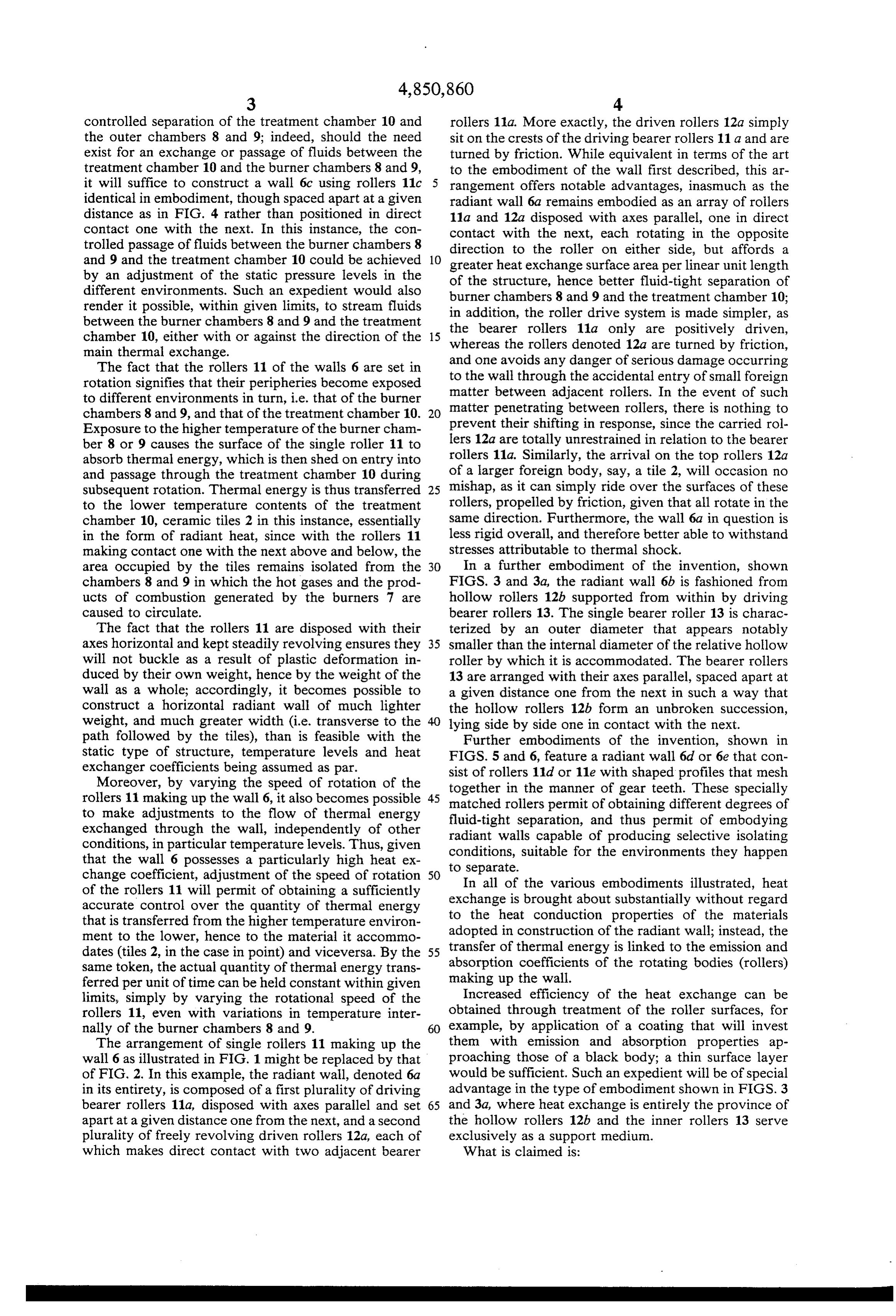
controlled separation of the treatment chamber 10 and rollers 11a. More exactly, the driven rollers 12a simply the outer chambers 8 and 9; indeed, should the need sit on the crests of the driving bearer rollers 11 a and are exist for an exchange or passage of fluids between the turned by friction. While equivalent in terms of the art treatment chamber 10 and the burner chambers 8 and 9, to the embodiment of the wall first described, this ar it will suffice to construct a wall 6c using rollers 11c 5 rangement offers notable advantages, inasmuch as the identical in embodiment, though spaced apart at a given radiant wall 6a remains embodied as an array of rollers distance as in FIG. 4 rather than positioned in direct 11a and 12a disposed with axes parallel, one in direct contact one with the next. In this instance, the con contact with the next, each rotating in the opposite trolled passage of fluids between the burner chambers 8 direction to the roller on either side, but affords a and 9 and the treatment chamber 10 could be achieved 10 greater heat exchange surface area per linear unit length by an adjustment of the static pressure levels in the of the structure, hence better fluid-tight separation of different environments. Such an expedient would also burner chambers 8 and 9 and the treatment chamber 10; render it possible, within given limits, to stream fluids in addition, the roller drive system is made simpler, as between the burner chambers 8 and 9 and the treatment the bearer rollers 11a only are positively driven, chamber 10, either with or against the direction of the 15 whereas main thermal exchange. the rollers denoted 12a are turned by friction, The fact that the rollers 11 of the walls 6 are set in and one avoids any danger of serious damage occurring rotation signifies that their peripheries become exposed to the wall through the accidental entry of small foreign to different environments in turn, i.e. that of the burner matter between adjacent rollers. In the event of such chambers 8 and 9, and that of the treatment chamber 10. 20 matter penetrating between rollers, there is nothing to Exposure to the higher temperature of the burner cham prevent their shifting in response, since the carried rol ber 8 or 9 causes the surface of the single roller 11 to lers 12a are totally unrestrained in relation to the bearer absorb thermal energy, which is then shed on entry into rollers 11a. Similarly, the arrival on the top rollers 12a and passage through the treatment chamber 10 during of a larger foreign body, say, a tile 2, will occasion no subsequent rotation. Thermal energy is thus transferred 25 mishap, as it can simply ride over the surfaces of these to the lower temperature contents of the treatment rollers, propelled by friction, given that all rotate in the chamber 10, ceramic tiles 2 in this instance, essentially same direction. Furthermore, the wall 6a in question is in the form of radiant heat, since with the rollers 11 less rigid overall, and therefore better able to withstand making contact one with the next above and below, the stresses attributable to thermal shock. area occupied by the tiles remains isolated from the 30 In a further embodiment of the invention, shown chambers 8 and 9 in which the hot gases and the prod FIGS. 3 and 3a, the radiant wall 6b is fashioned from ucts of combustion generated by the burners 7 are hollow rollers 12b supported from within by driving caused to circulate. bearer rollers 13. The single bearer roller 13 is charac The fact that the rollers 11 are disposed with their terized by an outer diameter that appears notably axes horizontal and kept steadily revolving ensures they 35 smaller than the internal diameter of the relative hollow will not buckle as a result of plastic deformation in roller by which it is accommodated. The bearer rollers duced by their own weight, hence by the weight of the 13 are arranged with their axes parallel, spaced apart at wall as a whole; accordingly, it becomes possible to a given distance one from the next in such a way that construct a horizontal radiant wall of much lighter the hollow rollers 12b form an unbroken succession, weight, and much greater width (i.e. transverse to the lying side by side one in contact with the next. path followed by the tiles), than is feasible with the Further embodiments of the invention, shown in static type of structure, temperature levels and heat FIGS. 5 and 6, feature a radiant wall 6d or 6e that con exchanger coefficients being assumed as par.
Moreover, by varying the speed of rotation of the sist of rollers 11d or 11e with shaped profiles that mesh together in the manner of gear teeth. These specially rollers 11 making up the wall 6, it also becomes possible 45 to make adjustments to the flow of thermal energy matched rollers permit of obtaining different degrees of fluid-tight separation, and thus permit of embodying exchanged through the wall, independently of other radiant walls capable of producing selective isolating conditions, in particular temperature levels. Thus, given conditions, suitable for the environments they happen that the wall 6 possesses a particularly high heat ex to separate.
change coefficient, adjustment of the speed of rotation 50 In all of the various embodiments illustrated, heat of the rollers 11 will permit of obtaining a sufficiently exchange is brought about substantially without regard accurate control over the quantity of thermal energy that is transferred from the higher temperature environ to the heat conduction properties of the materials adopted in construction of the radiant wall; instead, the ment to the lower, hence to the material it accommo dates (tiles 2, in the case in point) and viceversa. By the 55 transfer of thermal energy is linked to the emission and same token, the actual quantity of thermal energy trans absorption coefficients of the rotating bodies (rollers) ferred per unit of time can be held constant within given making up the wall.
Increased efficiency of the heat exchange can be limits, simply by varying the rotational speed of the rollers 11, even with variations in temperature inter obtained through treatment of the roller surfaces, for nally of the burner chambers 8 and 9. 60 example, by application of a coating that will invest The arrangement of single rollers 11 making up the them with emission and absorption properties ap wall 6 as illustrated in FIG. 1 might be replaced by that proaching those of a black body; a thin surface layer of FIG. 2. In this example, the radiant wall, denoted 6a would be sufficient. Such an expedient will be of special in its entirety, is composed of a first plurality of driving advantage in the type of embodiment shown in FIGS. 3 bearer rollers 11a, disposed with axes parallel and set 65 and 3a, where heat exchange is entirely the province of apart at a given distance one from the next, and a second the hollow rollers 12b and the inner rollers 13 serve plurality of freely revolving driven rollers 12a, each of exclusively as a support medium.
which makes direct contact with two adjacent bearer What is claimed is:
Page 6
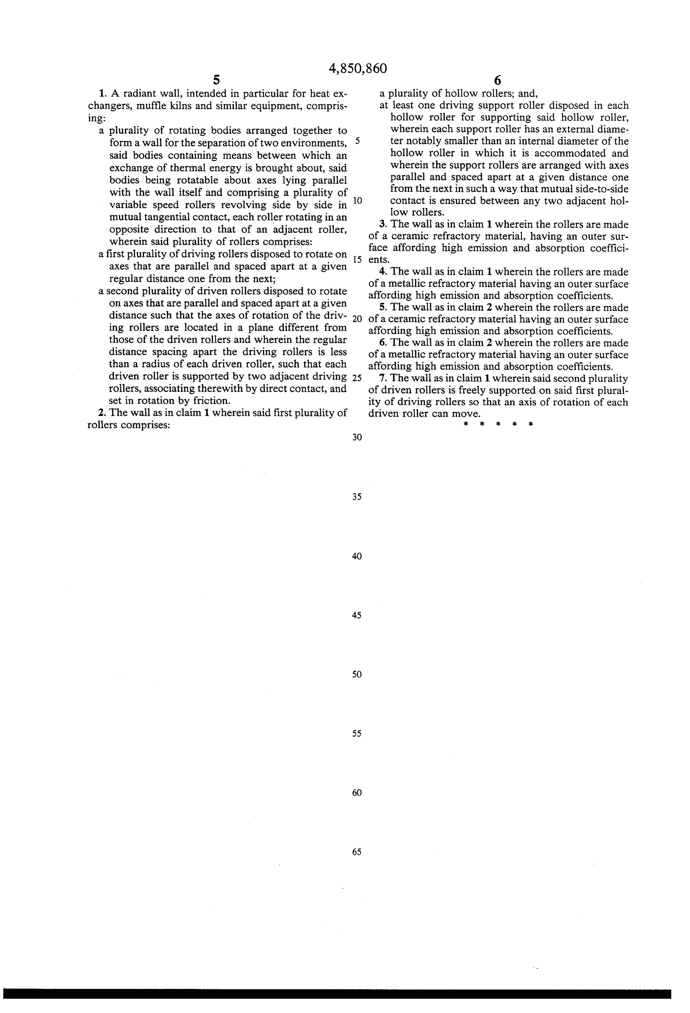
1. A radiant wall, intended in particular for heat ex a plurality of hollow rollers; and, changers, muffle kilns and similar equipment, compris at least one driving support roller disposed in each 1ng: hollow roller for supporting said hollow roller, a plurality of rotating bodies arranged together to wherein each support roller has an external diame form a wall for the separation of two environments, ter notably smaller than an internal diameter of the said bodies containing means between which an hollow roller in which it is accommodated and exchange of thermal energy is brought about, said wherein the support rollers are arranged with axes bodies being rotatable about axes lying parallel parallel and spaced apart at a given distance one with the wall itself and comprising a plurality of 10 from the next in such a way that mutual side-to-side variable speed rollers revolving side by side in contact is ensured between any two adjacent hol low rollers.
mutual tangential contact, each roller rotating in an 3. The wall as in claim 1 wherein the rollers are made opposite direction to that of an adjacent roller, of a ceramic refractory material, having an outer sur wherein said plurality of rollers comprises:
a first plurality of driving rollers disposed to rotate on 15 face affording high emission and absorption coeffici axes that are parallel and spaced apart at a given eats. 4. The wall as in claim 1 wherein the rollers are made regular distance one from the next; of a metallic refractory material having an outer surface a second plurality of driven rollers disposed to rotate affording high emission and absorption coefficients. on axes that are parallel and spaced apart at a given 5. The wall as in claim 2 wherein the rollers are made distance such that the axes of rotation of the driv 20 of a ceramic refractory material having an outer surface ing rollers are located in a plane different from affording high emission and absorption coefficients. those of the driven rollers and wherein the regular 6. The wall as in claim 2 wherein the rollers are made distance spacing apart the driving rollers is less of a metallic refractory material having an outer surface than a radius of each driven roller, such that each affording high emission and absorption coefficients. driven roller is supported by two adjacent driving 25 7. The wall as in claim 1 wherein said second plurality rollers, associating therewith by direct contact, and of driven rollers is freely supported on said first plural set in rotation by friction. ity of driving rollers so that an axis of rotation of each 2. The wall as in claim 1 wherein said first plurality of driven roller can move.
rollers comprises: k sk
Provenance
- Collection
- Cited prior art
- Original PDF
- patentimages.storage.googleapis.com →
- Filed
- 1988-05-16
- Pages
- 6
- Method
- pdftotext (the PDF's own text layer) + pdftoppm 300dpi page scans
- Source
- Google Patents bibliographic record
- Granted
- 1989-07-25
- Inventors
- Alberto Albonetti
- Transcribed from
- patentimages.storage.googleapis.com →