patent · US4794501
Indirect specular lamp
27 December 1988
Page 1 — bibliographic record
United States Patent (19) 11 Patent Number: 4,794,501 Bartenbach 45 Date of Patent: Dec. 27, 1988 (54) INDIRECTSPECULAR LAMP FOREIGN PATENT DOCUMENTS (75 Inventor: Christian Bartenbach, Munich, Fed. 2420022 11/1975 Fed. Rep. of Germany . Rep. of Germany 3440028 5/1985 Fed. Rep. of Germany. 73) Assignee: Siemens Aktiengesellschaft, Berlin OTHER PUBLICATIONS and Munich, Fed. Rep. of Germany "Objektleuchten' of Siemens AG, Catalog I 4.23, 1982, (21) Appl. No.: 863,182 p. 3/0.
Primary Examiner-Margaret A. Focarino (22 Filed: May 14, 1986 Attorney, Agent, or Firm-Hill, Van Santen, Steadman & 30 Foreign Application Priority Data Simpson
May 17, 1985 (DE) Fed. Rep. of Germany ....... 3517897 57 ABSTRACT The specular lamp or lighting fixture comprises a fluo 51) Int. Cl'................................................. F21J 7/00 rescent tube as a light bulb which is arranged largely 52 U.S.C. .................................... 362/298; 362/217; within a channel-shaped counter-reflector. Cross-lamel 362/260; 362/290 lae for blanking the light of the fluorescent tube out in 58) Field of Search ............... 362/217, 257, 260,290, the longitudinal direction are seated on the counter 362/298 reflector. A channel-shaped main reflector which is (56) References Cited designed large, and whose surface is preferably matted, is situated opposite the counter-reflector. A uniform
2,219,383 10/1940 Dillon ................................. 362/219 ture are achieved with the specular lamp. The lumi 3,671,735 6/1972 King ................................... 240/41.1 nance does not exceed a prescribed value in a pre 4,006,355 2/1977 Shemitz et al. ..... ... 362/290 X scribed, screened region.
4,310,876 l/1982 Small et al. ......................... 362/298 4,414,609 11/1983 Shenitz ................................. 362/33 11 Claims, 1 Drawing Sheet
Page 2
Drawing sheet — no readable text.
Page 3
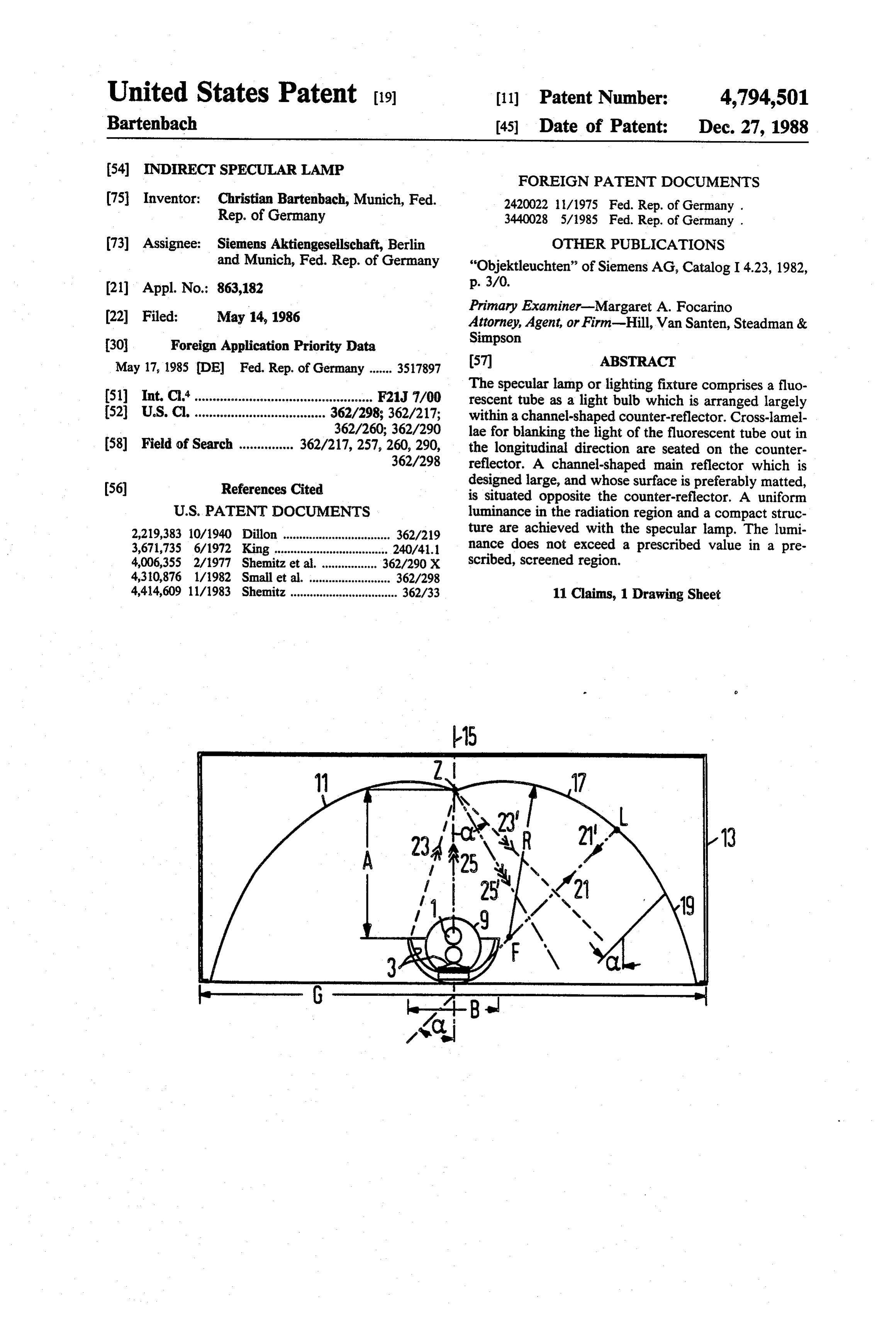
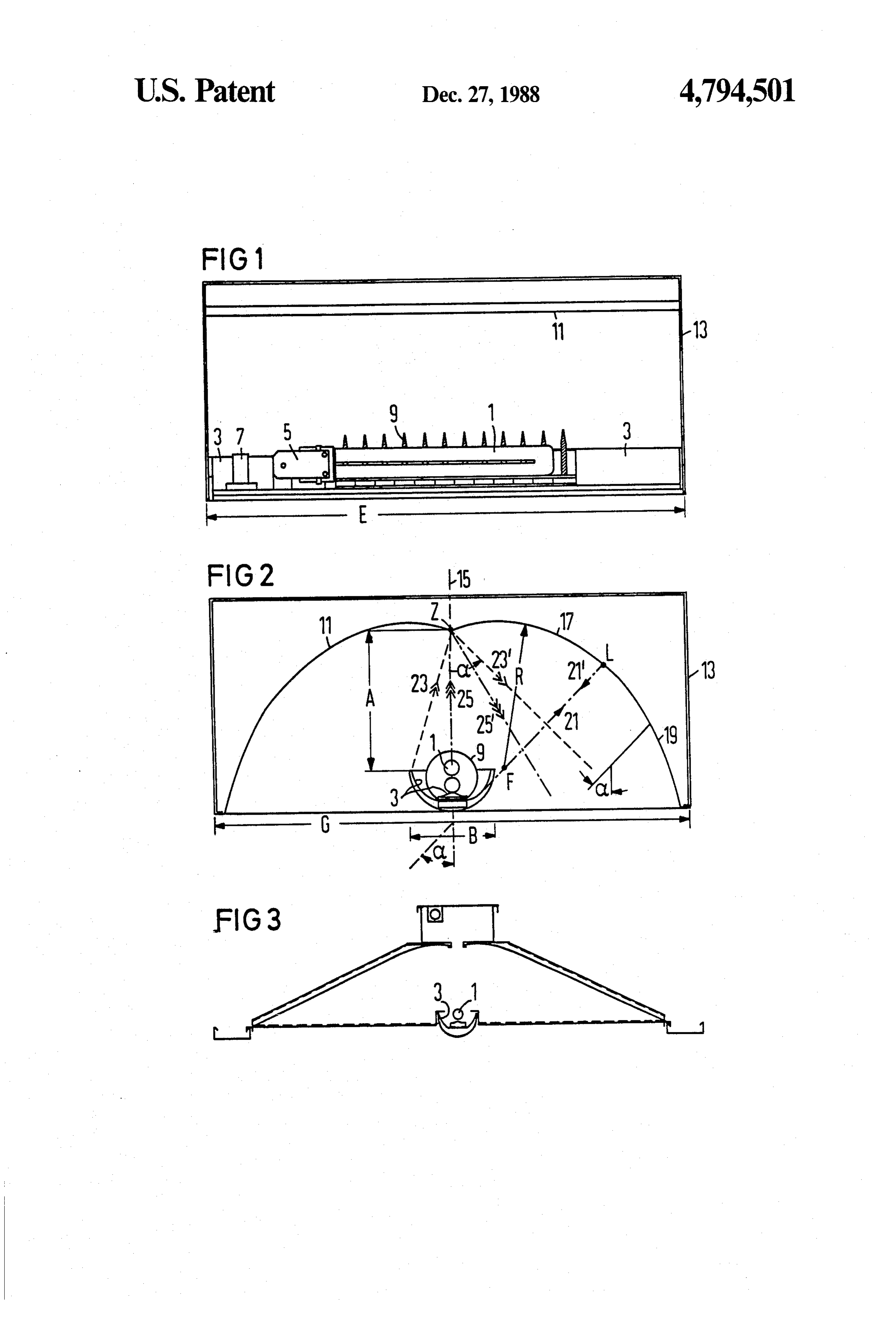
FIG. 2 is a sectional view at right angles to the view
NDIRECT SPECULAR LAMP of FIG. 1; and
FIG. 3 is a specular lamp comprisinga partly straight
BACKGROUND OF THE INVENTION design of the main reflector.
The invention relates to an indirect specular lamp 5 DESCRIPTION OF THE PREFERRED comprising a counter-reflector, a lamp arranged within EMBODIMENTS the counter-reflector and completely shielded there According to FIGS. 1 and 2, a bulb 1 is arranged from, and an at least partially curved main reflector within a counter-reflector or back-reflector 3 fashioned arranged opposite the counter-reflector and fashioned 10 as a channel. The light bulb 1 fashioned as a fluorescent larger than the counter-reflector. tube is surrounded and completely shielded by this In lighting technology, there is an effect to protect a channel. The fluorescent tube 1 is fashioned U-shaped, person situated at a certain distance from the lamp i.e. comprises against being dazzled. This person should thus not have to one anothertwo illumination paths conducted parallel a direct view of the lamp and should not be disturbed by 15 base 5 is mounted has and its end plugged into a base 5. The at a fastening part 7 secured to the glaring reflectors. An adequate brightness should also counter-reflector 3. The light bulb 1 is surrounded by be established for the intended purpose in the bean circular cross-lamellae 9 arranged at a distance from region of the lamp. These conditions are satisfactorily one another and which have a parabolic or triangular met by a specular lamp of the type initially cited which cross section known in screen lamps. is disclosed, for example, in the product brochure "Ob 20 This arrangement comprising counter-reflector 3 jektleuchten' of Siemens AG, Catalog I4.23 1982, page with fluorescent tube 1 is situated opposite a main re 3/0, incorporated herein. An indirect specular lamp flector 11. This has the shape of a channel which is comprising a halogen lamp within a counter-reflector or slightly indented in the region lying opposite the fluo back-reflector is shown therein. This arrangement is rescent tube 1, and is laterally secured to a housing 13. situated opposite a main reflector from which the light 25 The main reflector 11 is designed to be mirror-sym rays are reflected into the region to be illuminated. metric with respect to the center plane 15 which pro Above a screening angle-measured from the ver ceeds through the fluorescent tube 1. As seen in cross tical-the lamp has a screening region in which no light section, the main reflector 11 first has a circular arc is beamed out from the main reflector. Given a viewing portion 17 at both sides of the center plane 15, and this angle which is smaller than the screening angle (radia 30 is followed by an outer part designed here as a parabolic tion range), the lamp itself is covered by the counter curve portion 19. The size of each circular arc portion reflector or back-reflector. is defined by a limiting ray 21, 21' which is emitted from There have been recent efforts to also achieve a low a point Fat the edge or outside of the edge of the coun luminance in the radiation range. One reason for this is ter-reflector 3, retraces the same beam path (21') after that, given reflective work surfaces, for example, that 35 reflection in point L of the circular arc part 17, and reside under the lamp, a person working there will not describes the screening angle with the vertical. To be on be disturbed by an excessively great luminance when next the safe side, this outermost point F is placed somewhat looking at the reflective work surface. to the counter-reflector 3 in FIG. 2. The circular Specular lamps of the known type only have a low arc portion 17 is thus constructed up to the point L and merges there with the parabolic curve part 19. Both arc luminous flux. In order to uniformly illuminate larger parts 17, 19 have the same slope in point L. spaces, several of these illuminating devices are re The focus of the parabola on which the parabolic quired, this not always being economically justifiable. curve portion 19 is based in placed in the point F SUMMARY OF THE INVENTION through which its principal axis also proceeds. Instead of the parabolic curve portion 19, other outer
An object of the invention is to create a specular lamp 45 portions of the type initially cited having a higher luminous flux possible ashavingshown, flat proceeding curve shapes are also for example, in FIG. 3. Such outer wherein the luminance in the radiation range does not parts, however, necessarily produce a roomier struc exceed a prescribed value.
This object is achieved in accordance with the inven 50 tional cases. Such a case is can tural shape which, however, be desirable in excep tion in that the light bulb is a fluorescent tube, that the when the specular lamp is to be placed intofor established, example, a prescribed counter-reflector is fashioned channel-like, and is pro grid of, for example, 1.25 meters width as a ceiling vided with cross-lamellae for blocking off the lightbulb element.
in the longitudinal direction. In order to achieve a compact structure, the counter The desired, high luminous flux is assured by the use 55 reflector 3 and the main reflector 11 have as small as of the fluorescent bulb. The cross-lamellae at the coun possible a distance A from one another. This distance A ter-reflector guarantee that the luminance in the radia is dependent on the required screening angle a, and on tion region is also low when observed in the longitudi the width of the counter-reflector 3. The smallest dis nal direction. tance A results when a light ray 23 is emitted from the An especially advantageous development of the in 60 outer left edge of the counter-reflector 3 to the point A vention is that the main reflector-as seen in cross sec at the left edge of the right-hand circular arc portion 17, tion--is formed of two circular arc parts joined to one and is reflected from the latter at the screening angle a another, and of respective outer parts laterally attached as light ray23'. Given a short distance A, the prescribed thereto. A particularly low design of the specular lamp value for the screening angle would be exceeded. A is achieved by means of this technique. 65 light ray 25 which emanates in the region between the BRIEF DESCRIPTION OF THE DRAWINGS edges of the counter-reflector 3, for example directly from the light bulb 1, is reflected by the main reflector
FIG. 1 is a side view of an indirect specular lamp; 11 at an angle (light ray 25) that is smaller than the
Page 4
screening angle a. A high efficiency given observation positioned between said front region and said main of the secondary conditions for the screening region is reflector;
achieved by this design and arrangement of the main said light bulb being a fluorescent tube; and reflector 11. said counter-reflector being provided with cross The main reflector 11 comprises a diffusely reflective 5 lamellae means at least partially surrounding said inside surface which has a directivity (directionally lightbulb for screening said light bulb in a longitu reflected component) of between 20 and 40%. In the dinal direction of the light bulb. exemplary embodiment shown in FIGS. 1 and 2, for 2. A specular lamp according to claim 1 wherein a example, given an overall width G of the specular lamp cross sectional generated surface of said main reflector of about G = 60 cm, the directivity amounts to about O has two circular arc portions joined to one another, said 20%. Given a correspondingly larger main reflector 11 arc portions merging with respective outer portions. having a larger light emergence aperture, as shown 3. A specular lamp according to claim 2 wherein the later in FIG. 3, the directivity can be boosted to a value main reflector is matted and has a directivity of 20 to of about 40%. The main reflector 11 preferably has 40%.
about six times the width of the counter-reflector 3, i.e. 15 4. A specular lamp according to claim 3 wherein said G=6B applies. The length E of the main reflector 11 is main reflector has a width which is approximately six dependent on the lightbulb 1 used, and should therefore times a width of said counter-reflector. be at least equal to the width G of the main reflector 11. 5. A specular lamp according to claim 4 wherein a Pure or super-pure aluminum comes into consider length of said main reflector is at least equal to its width. ation as the material for the main reflector 11. Alterna 20 6. A specular lamp according to claim 5 wherein a tively, a plastic whose reflective surface is coated with length of said main reflector is between 30 and 160 cm. pure or super-pure aluminum can also be used. In order 7. A specular lamp according to claim 1 wherein a to achieve the diffuse reflection, the surface of the main cross-sectional generated surface of said main reflector reflector 11 is either roughened, lacquered, or coated. It is mirror-symmetric relative to a center plane through is also possible to provide the main reflector 11 with fine 25 said fluorescent tube and running along the longitudinal holes and to place a white layer behind these fine holes. direction of said light bulb and wherein the light bulb This additionally results in good noise damping. The and counter-reflector lie within the generated surface. inside of the counter-reflector 3 is likewise fabricated of 8. An indirect specular lamp, comprising: pure or super-pure aluminum. It is fashioned in a highe a counter-reflector;
gloss manner, i.e. mirroring. The end faces of the reflec 30 a light bulb arranged within said counter-reflector tors 3, 11 can have glossy or diffuse surfaces. and completely screened by it with respect to a Identical component parts are identified with the front illumination region of the lamp; same reference characters in FIG.3 as in FIGS. 1 and 2. an at least partially curved main reflector arranged Here, the two outer parts of the main reflector 11 are opposite said counter-reflector which is larger than uncurved, i.e. are fashioned with a straight cross sec 35 said counter-reflector and which faces the illumina tion. As a result, the specular lamp has large dimensions tion region;
which, however, can be desirable for aesthetic or struc said light bulb being a fluorescent tube; tural reasons. The descriptions to FIGS. 1 and 2 apply said counter-reflector having a channel-like shape by analogy to the structure and functioning of the spec and being provided with cross-lamellae means sur ular lamp of FIG. 3. 40 rounding said light bulb for screening said light Although various minor changes and modifications bulb in alongitudinal direction of the lightbulb and might be proposed by those skilled in the art, it will be perpendicular to a direction from the counter understood that I wish to include within the claims of reflector to the illumination region; and the patent warranted hereon all such changes and modi a cross-sectional generated surface of said main re fications as reasonably come within my contribution to 45 flector being mirror-symmetric relative to a center the art. plane through said fluorescent tube and running I claim as my invention: along the longitudinal direction of said light bulb. 1. An indirect specular lamp, comprising: 9. A specular lamp according to claim 8 wherein a a channel-like shaped counter-reflector; cross-sectional generated surface of said main reflector a light bulb arranged within said channel-like shaped 50 has two circular arc portions joined to one another, said counter-reflector and completely screened by it arc portions merging with respective outer portions. with respect to a front region to be illuminated by 10. A specular lamp according to claim 9 wherein the the lamp; outer portions are straight.
an at least partially curved main reflector arranged 11. A specular lamp according to claim 9 wherein the opposite said counter-reflector which is larger than 55 outer portions are parabolic.
said counter-reflector, said counter-reflector being
Provenance
- Collection
- Cited prior art
- Original PDF
- patentimages.storage.googleapis.com →
- Filed
- 1986-05-14
- Pages
- 4
- Method
- pdftotext (the PDF's own text layer) + pdftoppm 300dpi page scans
- Source
- Google Patents bibliographic record
- Granted
- 1988-12-27
- Inventors
- Christian Bartenbach; Siemens AG
- Transcribed from
- patentimages.storage.googleapis.com →