patent · US4792384
Method and apparatus for operating a fuel cell in combination with an electrochemical cell to produce a chemical product
20 December 1988
Page 1 — bibliographic record
United States Patent (19) 11 Patent Number: 4,792,384 Levy et al. 45) Date of Patent: Dec. 20, 1988 (54) METHOD AND APPARATUS FOR 4,084,038 4/1978 Scragg et al. ......................... 429/17 OPERATING A FUEL CELL IN 4,276,145 6/1981 Skala .............. . . 204/247 COMBINATION WITH AN 4,411,967 10/1983 Yano ..................................... 429/23 ELECTROCHEMICAL CELL TO PRODUCE FOREIGN PATENT DOCUMENTS
A CHEMICAL PRODUCT
(75) Inventors: Alexander H. Levy, Bloomfield;
Kenneth Lipman, West Hartford, OTHER PUBLICATIONS both of Conn. "Energy Saving in Chlorate Production with the Use of (73) Assignee: United Technologies Corporation, the Fuel Cell', I. H. Warren; Jun. 3, 1982. Hartford, Conn. Primary Examiner-Donald L. Walton (21) Appl. No.: 27,040 Attorney, Agent, or Firm-Gene D. Fleischhauer (22) Filed: Mar. 20, 1987 57 ABSTRACT A method and apparatus is disclosed for operating a fuel
Related U.S. Application Data cell 14 producing electrical energy in combination with 63 Continuation of Ser. No. 501,237, Jun. 3, 1983, aban an electrochemical cell 12 using electrical energy to doned. produce a chemical product. The electrolysis cell pro duces hydrogen for use as a fuel in the fuel cell and is 51 Int. Cl. ........................ C25B 1/02; C25B 15/00; linked with the fuel cell by a direct current converter 16 HO1M. 8/06 which allows the fuel cell to operate between an upper (52) U.S. Cl. ...................................... 204/129; 429/17; voltage limit and a lower voltage limit. The direct cur 429/23; 204/228 rent converter 16 employs a gated switch means, such (58) Field of Search ............................. 429/17, 19, 23; as a thyristor 98, to intermittently pass electrical power 204/129, 228 from the fuel cell to the electrochemical cell such that (56) References Cited the voltage drop across the direct current converter is
equal to the difference in voltage between the fuel cell and the electrochemical electrolysis cell.
3,180,813 4/1965 Wasp et al. ........................... 429/12 3,622,490 1 1/1971 Lockett ............................... 204/220 14 Claims, 7 Drawing Sheets
FUE CEL
Low PRESSURE conventional
SAM FUE
fell
PROCESSOR:
PurchASEA.C. PRODUCT H. ----
ELECTRICPOWER RecYCLED TO
FUELCE
HGHVOTAGE
A.C. Rectifier
SCMEAC. POWER
FFUN
choriNE
water
MAKEU ON-ST
ance
cAroos
PRESSure
SEAM
Page 2
Drawing sheet — no readable text.
Page 3
Drawing sheet — no readable text.
Page 4
Drawing sheet — no readable text.
Page 5
Drawing sheet — no readable text.
Page 6
Drawing sheet — no readable text.
Page 7
Drawing sheet — no readable text.
Page 8
Drawing sheet — no readable text.
Page 9
causing the fuel cell to require a larger amount of fuel
METHOD AND APPARATUS FOR OPERATING A for a given amount of power.
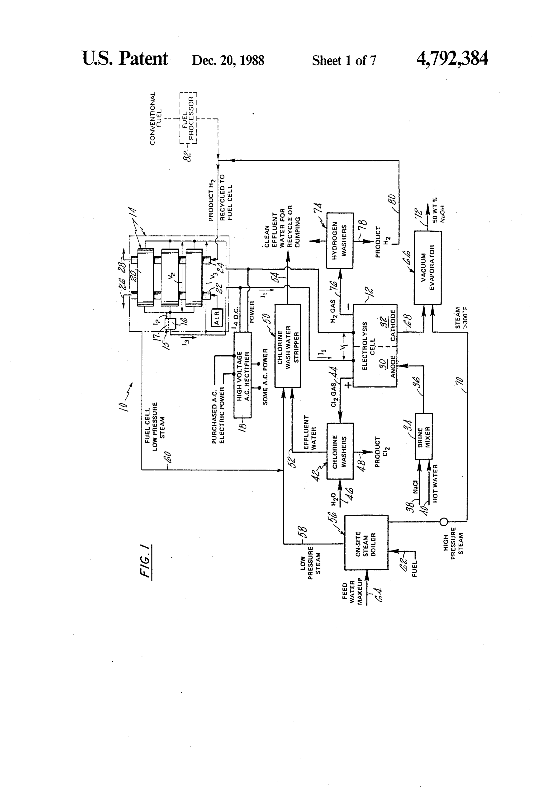
FUEL CELL IN COMBINATION WITH AN As shown in FIG. 2, fuel cells typically produce ELECTROCHEMICAL CELL TO PRODUCE A electrical energy with a voltage characteristic that de CHEMICAL PRODUCT creases as current increases. This graphical representa tion of voltage and current is often referred to as the
CROSS-REFERENCES TO RELATED voltage characteristic of the fuel cell. The voltage drops APPLICATIONS with increasing current because of ohmic and polariza tion losses. In addition, there is a voltage loss with time
This is a continuation of application Ser. No. 501,237, 10 due filed June 3, 1983 which is now abandoned. to the slow deterioration of catalysts used at the anode and cathode of the fuel cell.
DESCRIPTION This decreasing voltage characteristic of fuel cells 1. Technical Field causes difficulties in directly coupling the fuel cell to an This invention relates to a method for operating a fuel electrochemical cell to perform an electrochemical cell which produces electrical energy in combination 15 process. Examples of electrochemical cells that use electrical energy to produce a chemical product such as with an electrochemical cell which uses electrical en chlorine or caustic alkalis are shown in U.S. Pat. No.
ergy. More particularly, this invention is directed to a 4,031,000 method and apparatus for permitting the fuel cell and phragm For issued to Nakamura et al. entitled "Dia electrochemical cell to operate at voltages which are 20 kali', Electrolytic Production Of Caustic Al- . independent of each other. This invention has applica entitled "SolidPat.
Polymer Electrolyte Chlor-Alkali Elec tion to all types of fuel cells including acid, base, solid trolysis Cell' and in U.S. Pat. No. 4,273,626 entitled electrolyte and molten carbonate fuel cells and to all "Electrolyte Series Flow. In Electrolytic Chlor-Alkali types of electrochemical cells including cells that pro Cells', the information in which is incorporated herein duce a reactant for the fuel cell and cells that do not 25 produce a reactant for the fuel cell. by reference.
2. Background Art These electrochemical processes typically employ an A fuel cell is an electrochemical cell which consumes electrochemical cell having a voltage characteristic fuel and an oxidant on a continuous basis to generate of the fuel cell. Inin these which is opposite nature to the voltage characteristic electrical energy. The fuel is consumed at an anode and 30 saleable product is directlycells, the production of the proportional to the flow of the oxidant at a cathode. The anode and cathode are placed in electrochemical communication by an electro current ing through the cells. As shown in FIG. 2, increas voltages are required as the flow of electrical cur lyte. One typical fuel cell employs a phosphoric acid rent is increased through the electrochemical cell to electrolyte. The phosphoric acid fuel cell uses air to produce more product. The increasing voltages are provide oxygen as an oxidant to the cathode and uses a 35 needed to overcome ohmic and polarization losses in hydrogen rich stream to provide hydrogen as a fuel to the electrochemical cell and other losses which are the anode. After passing through the cell, the depleted similar air and fuel streams are vented from the system on a currenttoandthepower losses occuring in a fuel cell. Thus, as the consumption is increased in the elec continuous basis.
trochemical
A typical fuel cell power plant comprises one or more an efficient operating cell to produce more chemical product at point, the voltage increases. As stacks of fuel cells, the cells within each stack being the power supplied by the fuel cell increases to meet this connected electrically in series to raise the voltage po demand, the operating voltage of the individual cells is tential of the stack. A stack may be connected in parallel decreased.
with other stacks to increase the current generating Accordingly, scientists and engineers are seeking a capability of the power plant. Depending upon the size 45 way to match the performance of a fuel cell to an elec of the power plant, a stack of fuel cells may comprise a trochemical cell to combine the two cells in a cycle and half dozen cells or less, or as many as several hundred yet to allow the fuel cell to operate at a voltage most cells. Air and fuel are usually fed to the cells by one or beneficial to the fuel cell and the electrochemical cell to more manifolds per stack. Examples of typical fuel cell operate at a voltage most beneficial to the electrochemi power plants are shown in U.S. Pat. No. 3,585,078 is 50 cal cell.
sued to Sederquist et al. entitled "Method Of Reformer
Fuel Flow Control', U.S. Pat. No. 3,976,507 issued to DISCLOSURE OF INVENTION Bloomfield entitled "Pressurized Fuel Cell Power Plant According to the present invention, an electrochemi With Single Reacting Gas Stream'; and U.S. Pat. No. cal cell using electrical power at a first voltage to pro 4,202,933 issued to Riser, et al. entitled "Method For 55 duce a chemical product and a fuel cell using fuel to Reducing Fuel Cell Output Voltage To Permit Low produce electrical power at a second voltage are linked Power Operation'. The information contained in these by a device allowing the fuel cell to operate at the sec patents is incorporated herein by reference. ond voltage and the electrochemical cell to operate at Fuel cell components are designed to operate within the first voltage.
a band of predetermined voltages. Voltages above the 60 In accordance with one embodiment of the invention, predetermined maximum are avoided in acid cells be the electrochemical cell produces fuel which is con cause excessive voltages may damage internal equip sumed in the fuel cell.
ment and cause excessively fast corrosion of compo In accordance with the present invention, an electro nents such as the cathode. In all fuel cells, such high chemical cell is operated at a first current and a first voltages result in low power densities and uneconomi 65 voltage to produce a chemical product and a fuel cell is cal operation of the power plant. Voltages below a operated at a second voltage and a second current to predetermined minimum are avoided because such low produce power for the electrochemical cell by convert voltages adversely affect the efficiency of the fuel cell ing the power output of the fuel cell to a current and
Page 10
output voltage which matches the voltage of the elec BEST MODE FOR CARRYING OUT THE trochemical cell.
INVENTION
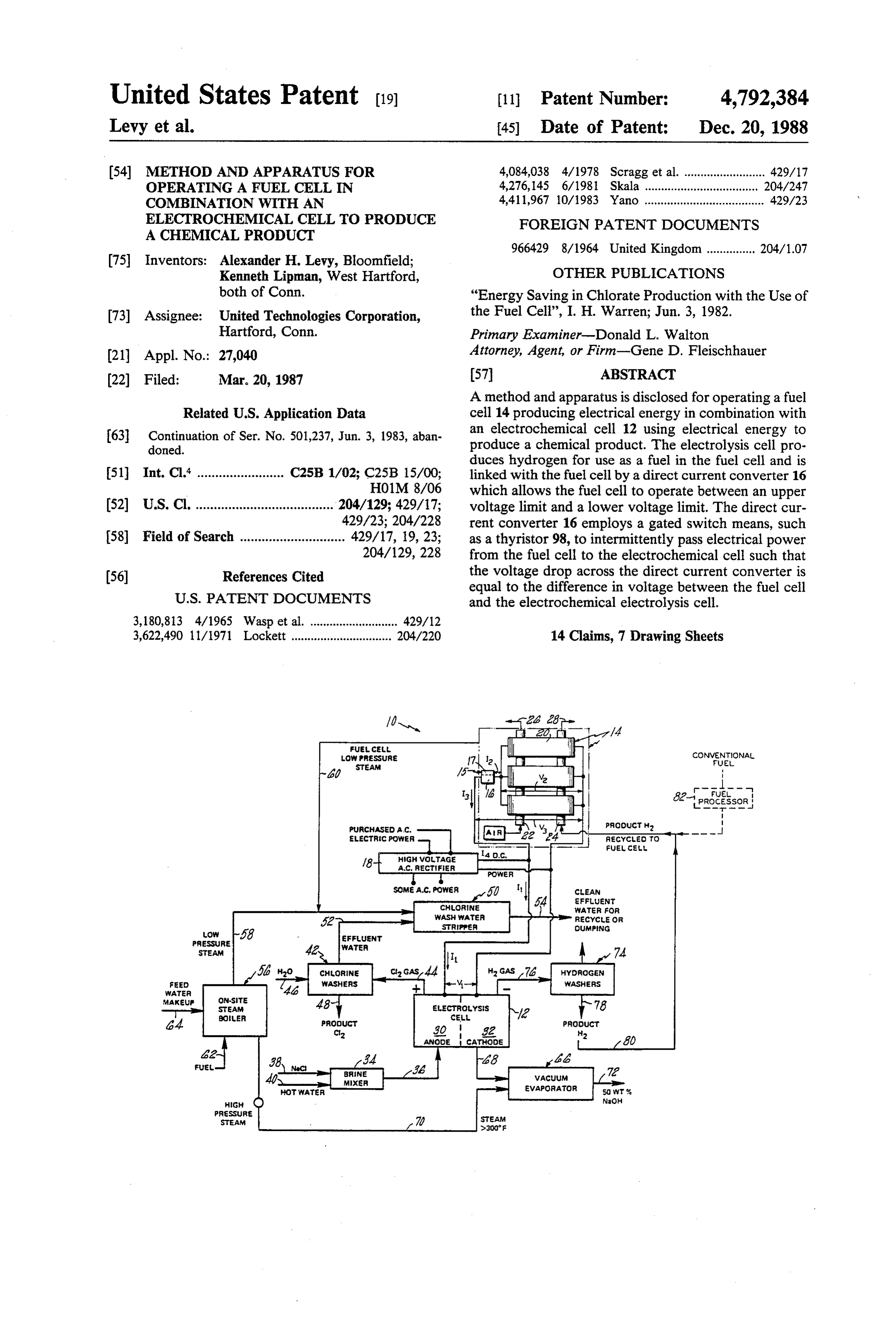
A primary feature of the present invention is a elec trochemical cell which uses power to produce a chemi FIG. 1 is a schematic representation of an embodi cal product efficiently at a first voltage. Another feature 5 ment of the present invention showing an apparatus 10 is a fuel cell which utilizes a fuel and an oxidant to for carrying out an electrochemical process to produce produce electrical power efficiently at a second volt a chemical product. The apparatus employs a chlor age. Another feature is a device for regulating the elec alkali electrochemical electrolysis cell 12 and an elec trical power received from the fuel cell. The device is 10 trochemical fuel cell 14 to produce chlorine and sodium connected to the fuel cell and electrochemical cell. In hydroxide. The term fuel cell includes a single fuel cell, one embodiment the electrochemical chemical cell is a a fuel cell stack formed of a plurality of fuel cells, and a chlor-alkali cell. In another embodiment the device for fuel cell power plant formed of one or more fuel cell regulating electrical power includes a direct current stacks. Similarly the term electrochemical cell or elec converter having a duty cycle to provide for the inter 15 trolysis cell includes a single electrochemical cell, an mittent flow of current through the direct current con electrochemical cell stack formed of a plurality of elec verter. The converter may be responsive to voltage, trochemical cells, and an electrochemical plant formed (i.e., a voltage regulator) or responsive to current (i.e., a ofRegulator one or more electrochemical stacks.
means for regulating the power received current regulator).
A primary advantage of the present invention is the 20 saidfrom the fuel cell 14 to adjust the voltage and current of efficiency which results from carrying out an electro power and for supplying the power to the electrol chemical process by combining a fuel cell with an elec ysis cell are connected to the fuel cell and to the elec trolysis cell. An example of such a means is a direct trochemical cell and allowing the fuel cell and the elec current regulator 15 having a direct current converter trochemical cell to operate at preferred voltages and currents independent of each other. In one embodiment, 25 is16connected and a control means 17. The direct current converter an advantage is the efficient utilization of a by-product cell. A high tovoltage,both the fuel cell and the electrolysis of the electrochemical process as fuel in the fuel cell. In communication with aAC rectifier 18 is in electrical source of purchased electric one embodiment, an advantage is the reduction in the average cost of electrical power by supplementing elec power. The rectifier is capable of supplying direct cur rent power to the electrolysis cell under selected oper trical power supplied from an outside source with 30 ating conditions. Under such operating conditions the power provided by the fuel cell. fuel cell supplies at least a portion of the power required The foregoing features and advantages of the present by the electrochemical cell.
invention will become more apparent in the light of the The fuel cell 14 shown in FIG. 1 is formed of at least following detailed description of the best mode for one individual fuel cell and in fact is a power plant carrying out the invention and in the accompanying 35 which includes pluralities of fuel cells stacked in series drawing. to form fuel cell stacks 20. The fuel cell stacks are con BRIEF DESCRIPTION OF DRAWINGS nected electrically in parallel to form the power plant. The fuel cell includes a manifold 22 and a manifold 24
FIG. 1 is a diagrammatic representation of an appara for supplying reactant gases to the fuel cell. A flow path tus for carrying out an electrochemical process, the 26 for oxidant rich gas stream, such as air, extends apparatus including an electrochemical cell and a fuel through the manifold 22 and a flow path 28 for fuel rich cell. gases, such as a hydrogen rich gas stream, extends FIG. 2 is a graphical representation of the voltage through the stacks to provide the cathode of each cell characteristic of a typical fuel cell and the voltage char with an oxidant and the anode of each cell with fuel. acteristic of a typical electrochemical cell.
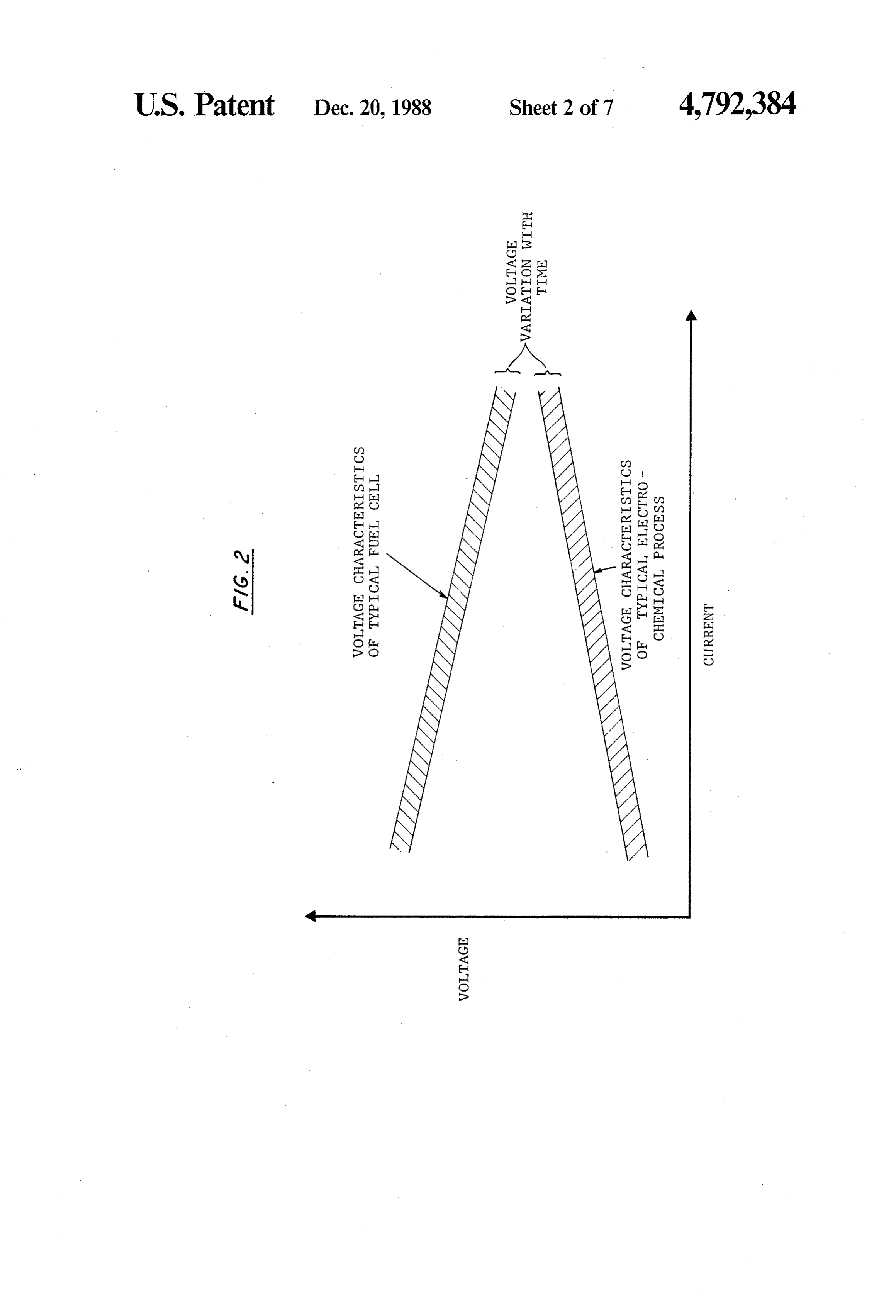
FIG. 3 is a diagrammatic representation of the rela Under normal operating conditions the fuel cell will not
consume all of the oxidant in the oxidant stream nor will tionship between the fuel cell, the electrochemical cell the fuel cell consume all of the fuel in the fuel stream. and regulator means connected to the fuel cell and the The electrolysis cell 12 has an anode side 30 and a electrochemical cell. cathode side 32. A brine mixer 34 is connected to the FIG. 4 is a schematic illustration of one embodiment 50 anode side via conduit 36. The brine mixer receives of a direct current converter used in regulating electri sodium chloride via conduit 38 and hot water via con cal power between the fuel cell and the electrochemical duit 40 to form brine. A plurality of chlorine washers 42 cell. are connected to the anode side by conduit 44. The FIG. 5 is a schematic illustration of a second embodi chlorine washers receive water via conduit 46 and dis ment of a direct current converter used in regulating 55 charge product chlorine via conduit 48. A stripper 50 electrical power between the fuel cell and the electro for the chlorine wash water is connected to the chlorine chemical cell. washers by conduit 52. The stripper discharges clean FIG. 6 is an alternate embodiment of the device water for recycling or dumping via conduit 54. An shown in FIG. 4. on-site steam boiler 56 is in flow communication with FIG. 7 is an alternate embodiment of the device 60 the stripper via conduit 58. The stripper also receives shown in FIG. 5. steam from the fuel cell via conduit 60. Alternatively, FIG. 8 is a graphical representation illustrative of the conduit 60 might be connected to other components wave forms used to explain the operation of the direct requiring steam, such as the brine mixer 34 or other current converter shown in FIG. 4 and FIG. 6 components requiring heat.
FIG. 9 is a graphical representation illustrative of 65 The on-site steam boiler 56 receives fuel via conduit wave forms used to explain the operation of the direct 62 and feed water via conduit 64. A vacuum evaporator current converter shown in FIG. 5 and FIG. 6. with 66 for processing sodium hydroxide received from the reference to the wave forms shown in FIG. 8. cathode side of the electrolysis cell via conduit 68 also
Page 11
receives high pressure steam from the boiler via conduit responsive to the output power of the fuel cell. The 70. The temperature of the steam is greater than 300' F.
The vacuum evaporator discharges fifty percent by direct current regulator includes the direct current con verter 16 and the control means 17. An example of a weight sodium hydroxide via conduit 72. A hydrogen control means is a microcomputer having analog to washer 74 receives hydrogen gas from the cathode side digital signal converters which develops a duty cycle of the electrolysis cell via conduit 76. The hydrogen response of two preselected parameters. The control discharges water via conduit 78 and supplies the fuel means develops a duty cycle signal for the converter. cell 14 with a hydrogen rich fuel stream via conduit 80. For example, the duty cycle may be set as a result of a The conduit 80 is connected to the hydrogen manifold difference between the actual current I3 flowing from 24 of the fuel cell. 1.O
Other electrochemical cells might be used in combi might be set asina comparison the regulator function of with a desired current or the voltage of the electro nation with the fuel cell 14. One example is a chlorate chemical cell and the actual voltage electrolysis cell which uses input electrical power to shown in FIG. 8 and FIG. 9, the dutyofcycle the fuel cell. As signal may produce a chlorate product and hydrogen. As with the chlor-aklaki process, hydrogen is produced at the cath- 1 5 be sent to the regulator in the form of a plurality of ode and the chlorate product is produced as a result of energizing gate signals to gated switch means. In addi the electrochemical process at the anode. The product tion, the control means has the capability of energizing is sent to a reactor for further processing. The hydrogen up components in the direct current converter during start is preferably processed through a hydrogen washer operations.
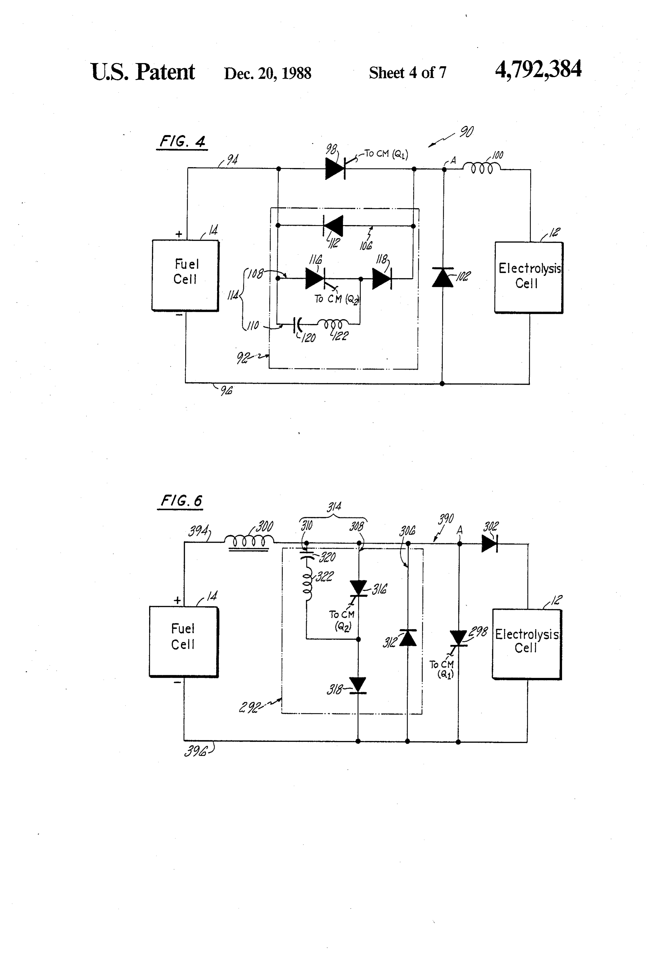
before FIG.
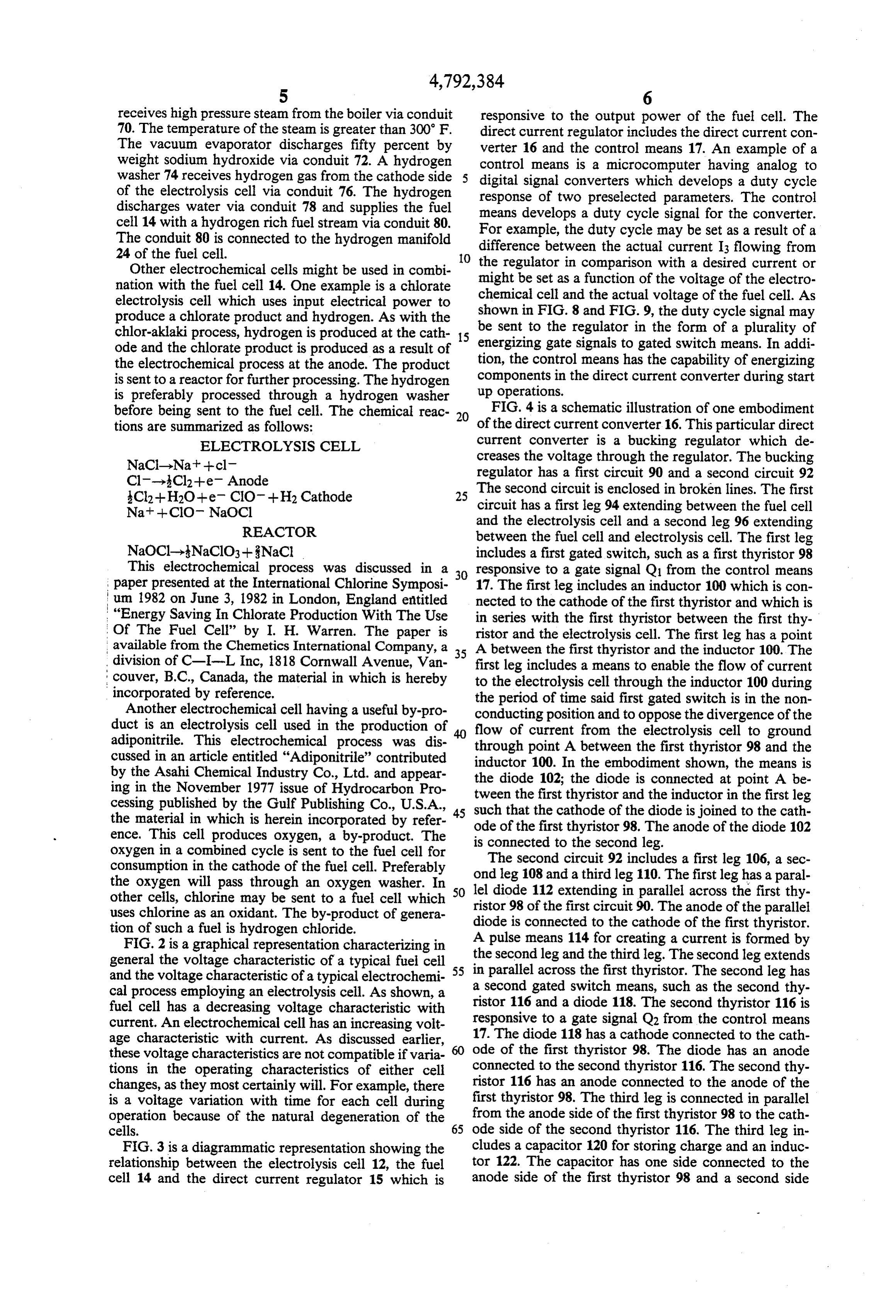
being sent to the fuel cell. The chemical reac- 20 of the direct 4 is a schematic illustration of one embodiment tions are summarized as follows: current converter 16. This particular direct ELECTROLYSIS CELL current converter is a bucking regulator which de NaCl-Nat -- cl creases the voltage through the regulator. The bucking Cl-3Cl2--e. Anode regulator has a first circuit 90 and a second circuit 92 The second circuit is enclosed in broken lines. The first
Cl2 + H2O+e CIO + H2 Cathode 25 circuit has a first leg 94 extending between the fuel cell Na+--CIO NaOCl
REACTOR
and the electrolysis cell and a second leg 96 extending between the fuel cell and electrolysis cell. The first leg
NaOCl.--NaClO3--NaCl includes a first gated switch, such as a first thyristor 98 This electrochemical process was discussed in a 3O responsive to a gate signal Q1 from the control means paper presented at the International Chlorine Symposi 17. The first leg includes an inductor 100 which is con I um 1982 on June 3, 1982 in London, England entitled nected to the cathode of the first thyristor and which is "Energy Saving In Chlorate Production With The Use in series with the first thyristor between the first thy Of The Fuel Cell” by I. H. Warren. The paper is ristor and the electrolysis cell. The first leg has a point available from the Chemetics International Company, a 3 5 A between the first thyristor and the inductor 100. The division of C-L-L Inc, 1818 Cornwall Avenue, Van first leg includes a means to enable the flow of current couver, B.C., Canada, the material in which is hereby to the electrolysis cell through the inductor 100 during incorporated by reference. the period of time said first gated switch is in the non Another electrochemical cell having a useful by-pro conducting position and to oppose the divergence of the duct is an electrolysis cell used in the production of flow of current from the electrolysis cell to ground adiponitrile. This electrochemical process was dis 40 through point A between the first thyristor 98 and the cussed in an article entitled "Adiponitrile' contributed inductor 100. In the embodiment shown, the means is by the Asahi Chemical Industry Co., Ltd. and appear the diode 102; the diode is connected at point A be ing in the November 1977 issue of Hydrocarbon Pro tween the first thyristor and the inductor in the first leg cessing published by the Gulf Publishing Co., U.S.A., 45 such the material in which is herein incorporated by refer ode of thethe that cathode of the diode is joined to the cath first thyristor 98. The anode of the diode 102 ence. This cell produces oxygen, a by-product. The is connected to the second leg. oxygen in a combined cycle is sent to the fuel cell for consumption in the cathode of the fuel cell. Preferably ondThe second circuit 92 includes a first leg 106, a sec leg 108 and a third leg 110. The first leg has a paral the oxygen will pass through an oxygen washer. In 5O lel diode other cells, chlorine may be sent to a fuel cell which ristor 98 of112 the extending in parallel across the first thy first circuit 90. The anode of the parallel uses chlorine as an oxidant. The by-product of genera diode is connected to the cathode of the first thyristor. tion of such a fuel is hydrogen chloride.
FIG. 2 is a graphical representation characterizing in A pulse means 114 for creating a current is formed by general the voltage characteristic of a typical fuel cell the second leg and the third leg. The second leg extends and the voltage characteristic of a typical electrochemi 5 5 in parallel across the first thyristor. The second leg has cal process employing an electrolysis cell. As shown, a a second gated switch means, such as the second thy fuel cell has a decreasing voltage characteristic with ristor 116 and a diode 118. The second thyristor 116 is current. An electrochemical cell has an increasing volt responsive to a gate signal Q2 from the control means age characteristic with current. As discussed earlier, 17. The diode 118 has a cathode connected to the cath these voltage characteristics are not compatible if varia ode of the first thyristor 98. The diode has an anode tions in the operating characteristics of either cell ristor connected to the second thyristor 116. The second thy changes, as they most certainly will. For example, there 116 has an anode connected to the anode of the is a voltage variation with time for each cell during first thyristor 98. The third leg is connected in parallel operation because of the natural degeneration of the from the anode side of the first thyristor 98 to the cath cells. 65 ode side of the second thyristor 116. The third leg in FIG. 3 is a diagrammatic representation showing the cludes a capacitor 120 for storing charge and an induc relationship between the electrolysis cell 12, the fuel tor 122. The capacitor has one side connected to the cell 14 and the direct current regulator 15 which is anode side of the first thyristor 98 and a second side
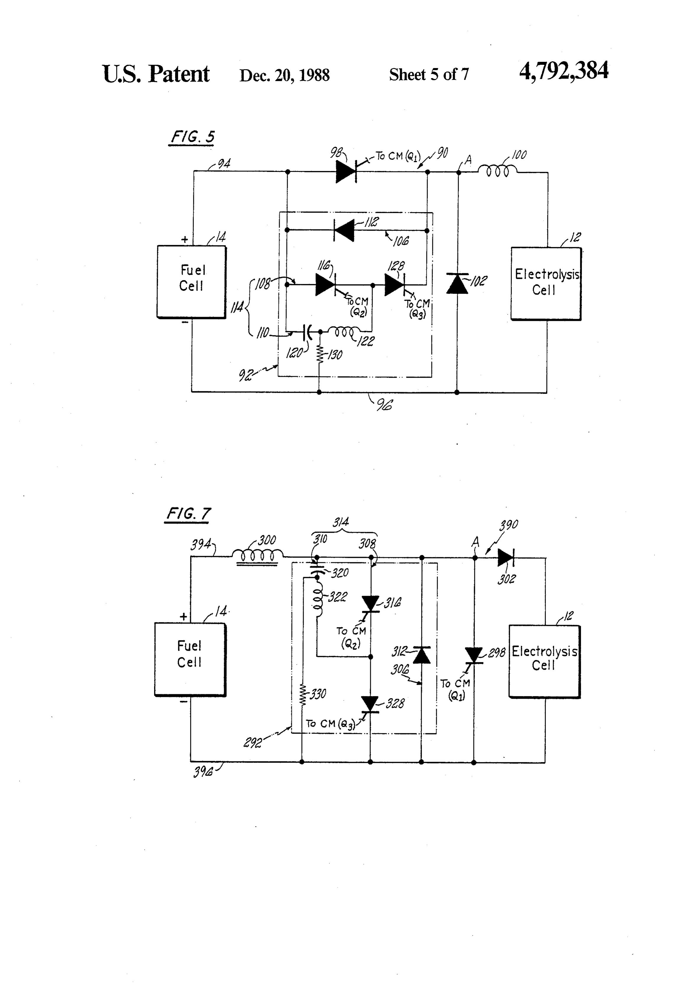
Page 12
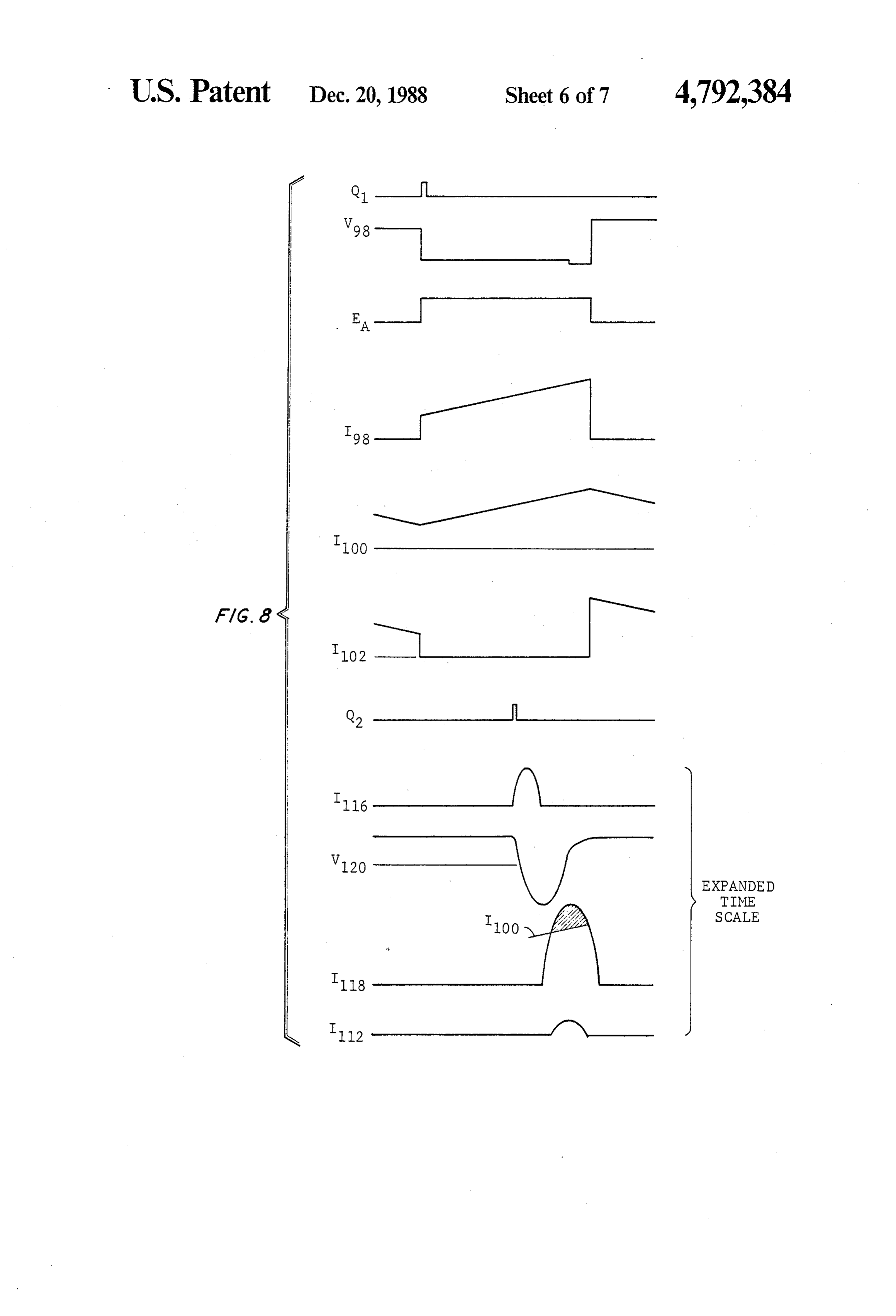
connected to the inductor 122 and connected through FIG. 7 is an alternate embodiment of the boosting the inductor to the cathode side of the second thyristor regulator shown in FIG. 6 with two modifications to 116. the second circuit 292. The first modification is the FIG. 5 is an alternate embodiment of the bucking substitution of a third gated switch means, such as the regulator shown in FIG. 4 witn two modifications to third thyristor 328, for the diode 318. The third thy the second circuit 92. The first modification is the sub ristor is responsive to a gate signal Q3 from the control stitution of a third gated switch means, such as the third means 17. The second modification is the addition of a thyristor 128, for the diode 118. The third thyristor 128 resistor 330 which extends from a point between the is responsive to a gate signal Q3 from the control means capacitor 320 and the inductor 322 in the third leg of the 17. The second modification is the addition of a resistor 10 second circuit to the second leg of the first circuit 396. 130 which extends from a point between the capacitor Operation of these different embodiments of the regu 120 and the inductor 122 in the third leg to the second lator is illustrated by the wave forms shown in FIG. 8 leg of the first circuit 96. and FIG. 9. These wave forms are a simplified represen FIG. 6 is a schematic illustration of another embodi tation for clarity of the complex wave forms that occur ment of the direct current converter 16. This particular 15 during operation. They are simplified for purposes of explanation.
direct current converter is a boosting regulator which increases the voltage through the regulator. The boost These wave forms include the Q1 wave form which is ing regulator has a first circuit 390 and a second circuit a control wave form generated by the control means. 292. The second circuit is enclosed in broken lines. The The Q1 wave form is applied to the gate of thyristor 98. 20 If the voltage at the anode is positive with respect to the first circuit has a first leg 394 extending between the fuel cell and the electrolysis cell and a second leg 396 ex cathode, the thyristor Q1 conducts when the positive tending between the fuel cell and electrolysis cell. The form is the isvoltage voltage Q1 applied gate to cathode. The second wave change across thyristor 98 from the first leg includes a first gated switch, such as a first anode to the cathode. The third wave form is the volt thyristor 298 responsive to a gate signal Q1 from the 25 age with respect to ground control means 17. The first thyristor has an anode con The fourth wave form is the EA at point A in the circuit. current I98 through the first nected to the first leg and a cathode connected to the thyristor 98. The wave form I100 is the current through second leg. The first leg includes an inductor 300 which the inductor 100 and is a measure of the current sup is connected to the anode of the first thyristor. The first leg has a point Abetween the first thyristor 298 and the 30 plied to the electrochemical cell. The wave form I102 is inductor 300. The inductor 300 is between point A and the current through the diode 102. The wave form Q2 is the fuel cell. The first leg includes a means to enable the applied as awave a control form from the microcomputer and is positive pulse to the gate of thyristor Q2. At flow of current to the electrolysis cell through the in the time of application, Q2 is a measure of the voltage ductor 300 during the period of time said first gated
Switch is in the nonconducting position and to oppose 35 from gate to cathode of the thyristor. The wave form I116 is the current flowing through the second thyristor the divergence of the flow of current from the electrol 116. The voltage V120 is the voltage relative at point C ysis cell to ground through point A between the first at the side of the capacitor 120 joined to the anode of thyristor 298 and the inductor 300. In the embodiment the first thyristor and to a measure of the voltage across shown, the means to enable and to oppose is a diode 302 th capacitor 120. The wave form I118 is the current having an anode connected at point Abetween the first through diode 18. Superimposed on I118 is a line show thyristor and the inductor in the first leg and having a ing the current 100 flowing at the same point in time cathode connected directly to the electrolysis cell by through the inductor 100. The current I112 is the current the first leg. Thus, the diode 302 is between point A and through the diode D112.
the electrolysis cell. During operation of the apparatus 10, brine is fed The second circuit 292 includes a first leg 306, a sec 45 from the brine mixer via conduit 36 to the anode side of ond leg 308 and a third leg 310. The first leg has a paral the electrolysis cell. The chlorine, present as chloride lel diode 312 extending in parallel across the first thy ion in the solution, forms chlorine according to the ristor 298 of the first circuit 390. The anode of the paral reaction: 2Clt-Cl2 +2e. The alkali metal ion and its lel diode 312 is connected to the cathode of the first water of hydration pass through a permionic membrane thyristor. A pulse means 314 for creating a current is 50 to the cathode side 32 of the electrochemical cell. The formed by the second leg and the third leg. The second water may be fed both externally into the cathode side leg extends in parallel across the first thyristor. The or fed as water of hydration passing to the cathode side. second leg has a second gated switch means, such as the The cathodic reaction is H2O-le-OH -- H2. The second thyristor 316, and a diode 318. The second thy chlorine gas evolved is sent to a chlorine washer via ristor 316 is responsive to a gate signal Q2 from the 55 conduit 44 where the chlorine gas is mixed with water control means 17. The diode 318 has a cathode con to remove contaminants. Wash water discharged from nected to the cathode of the first thyristor 298. The the chlorine washer 52 is flowed to the stripper 50 for diode 318 has an anode connected to the cathode of the chlorine where the water is mixed with low pressure second thyristor 316. The second thyristor 316 has an steam. The overall requirement for fuel for the process anode connected to the anode of the first thyristor 298. 60 is reduced if low pressure steam is recirculated from the The third leg is connected in parallel from the anode fuel cell to transfer heat from the fuel cell to the electri side of the first thyristor 298 to cathode side of the cal chemical process. After processing the water dis second thyristor 316. The third leg includes a capacitor charged from the chlorine washer through the stripper, 320 for storing charge and an inductor 322. The capaci the cleaned water is discharged from the process. The tor has one side connected to the anode side of the first 65 water may be recycled to the process or dumped. thyristor 298 and a second side connected to the induc The on-site steam boiler 56 provides high pressure tor 322. The second side is also connected through the steam to the vacuum evaporator where sodium hydrox inductor to the cathode side of the second thyristor. ide solution from the cathode is treated by evaporation.
Page 13
The resultant solution is approximately fifty percent fier, the current I will be the summation of the current (50%) by weight sodium hydroxide. The hydrogen gas I3 and I4.
evolved at the cathode is sent to a hydrogen washer As shown in FIG. 3, the direct current converter 16 which removes containments from the hydrogen gas. is designed to intermittently pass electrical current. The The water is discharged from the hydrogen washer and 5 amplitude of the output current is the weighted average the product hydrogen is sent via conduit 80 to the fuel of the current intermittently flowing through the direct cell 14 for consumption of at least a portion of the hy current converter. This amplitude is a function of the drogen in the fuel cell. duration of time during which current is allowed to pass In an alternate embodiment, conventional fuel may be through the direct current converter during any given treated by a fuel processor 82 to provide additional 10 period of time. The period of time current flows as a hydrogen to the fuel cell. If enough hydrogen is pro percentage of the given period of time is called the duty vided to the fuel cell the process can dispense with the cycle. Thus a fifty percent duty cycle results in the use of additional DC power. It is expected that the most passage of current for fifty percent of any period of efficient operation of the fuel cell of the overall process time. As discussed earlier, the duty cycle is established will result in the maximum possible consumption of the 15 in response to input signals which establish an error product hydrogen in the fuel cell to provide electrical signal. The control means 17 uses these signals to deter energy to the electrolysis cell and to decrease the reli mine the length of time between a pulse Q1 turning on ance of the process on purchased AC electric power the direct current converter to allow the direct current from an outside source. converter to pass current and a pulse Q2 turns off the The electrochemical cell uses electrical power at a 20 direct current converter. The length of time from the predetermined voltage and a predetermined current to first pulse to the subsequent pulse Q1 which turns on the produce the chemical product Depending on the num current converter is the period of time used to calculate ber of electrochemical cells which are grouped together the duty cycle. If the current converter is acting as a voltage regulator, the input signals will be the output and the configuration of the individual cells, this prede voltage of the current converter and the desired voltage termined voltage and current results in a requirement of 25 which a first voltage V1 and a first current I for the electro which may may be sent by an operator or automatically chemical cell stack. be automatically established by the system. As a result
Each fuel cell utilizes fuel and oxidant to supply elec lished and the of the error signal. A duty cycle is estab trical power at a second current and a second voltage. 30 a variable resistancecurrent converter is operated to provide These voltages V1 and V2 and currents I and I2 are through the regulator.by Finally, intermittently passing current a duty cycle will be selected to optimize the performance of the overall reached which results in a zero error.
process. Normally the fuel cell will be operated within Alternatively, and most preferably, the direct current aband of voltages which represents the optimum condi converter acts as a current regulator sensing the output tions for the individual fuel cell in terms of life, effi- 35 current on the regulator and establishing an error signal ciency and economics. For acid fuel cells this band has in response to a desired current. The control means been found to lie between a lower limit of fifty percent determines the error between the desired currentaand (50%) of the open circuit voltage and an upper limit the actual current establishing a new duty cycle for the which is equal to sixty-five percent (65%) of the open current converter and adjusting the duty cycle of the circuit voltage of the individual fuel cell. Similar ranges 40 current converter until the correct current as an output have been established for aklaline and molten carbonate is established. The desired current may be set, for exam fuel cells. Preliminary estimates have established the ple, to consume all of the hydrogen which is being following ranges: for molten carbonate fuel cells fifty produced by the electrochemical cell in which case the percent (50%) to sixty-five percent (65%) of the open microcomputer may sense the hydrogen input to the circuit voltage; for alkaline fuel cells the range is equal 45 fuel cell (e.g., signal F) and use a lookup table to deter to seventy percent (70%) to eighty percent of the open mine the output current of the fuel cell. Then, using the circuit voltage. In some situations it may be desirable voltage available from the electrochemical cell the mi for reasons not connected with efficiency or with dura crocomputer will determine the current which must be bility of the fuel cell to operate the fuel cell at voltages delivered by the converter. Any increase in hydrogen which are different from the band of predetermined 50 output is accompanied by an increase in the amount of values for the fuel cell or for the band of balues for the current that can be delivered and the concomitant de fuel cell which results in the most efficient operation of crease in the electrical power purchased until the total the process. power going to the electrolysis cell satisfies the operat Placing the individual cells in series to form a stack ing requirements of electrolysis cell. In one embodiment and placing the stacks in parallel to provide additional 55 additional hydrogen is produced by processing fuel current results in a utilization of fuel and oxidant which through a fuel processor such that the maximum current produces electrical power at a second voltage V2 and a available from the fuel cell to the electrolysis cell satis second current I2. After regulating the direct current fies the electrolysis cell so that no additional electrical power by passing the power through the direct current power need be purchased.
converter, a current I3 is supplied to the electrochemi- 60 During operation of the buck regulator, the anode cal cell at voltage V3 which matches the voltage V1. side of thyristor 981 has a voltage which is equal to the Purchased electrical power supplied by the rectifier at a voltage supplied by the fuel cell E?c. As shown in FIG. current I4 is supplemented by the current I3 and, under 8, during the time thyristor 98 is in the off position, the certain operating conditions, may be replaced entirely anode is positive with respect to the cathode as is shown by the current I3 resulting in the disconnection of the 65 by the waveform V98. The waveform Q1 describes the AC power supply from the circuit. In those cases the pulses which are placed on the gate of thyristor 98 and current I3 will equal I. Under operating conditions in the gate to cathode voltage of thyristor 98. At time which the electrical power is also provided by the recti equal zero, the Q1 waveform or control waveform is a
Page 14
pulse which is a step function having a width of some thyristor 98 seeks to go to point C which is no at microseconds. The pulse is applied gate to cathode and -Ef-|-c and does not flow to point A which is at a causes the thyristor 98 to conduct. The voltage V.98 voltage equal to Ef-c. Thus, the current I98 is shunted across the thyristor goes to zero because once the thy and replaced by a portion of the current I118. Alterna ristor is in conduction, the voltage drop across the thy tively, the process may be described as the production ristor is essentially zero. By placing the positive pulse of a pulse of current through diode 118 which may go on the gate of the thyristor, a positive voltage from gate through diode 112 or towards point A. The current I100 to cathode results and the thyristor becomes conducting is still building up, and, as the large pulse of current I118 because the voltage from the anode to the cathode was approaches point A, the inductor prevents an instanta positive. 10 neous increase in the current. As a result, the current At point C on the positive side of the capacitor, the I98 no longer flows, the current I100 is replaced by a capacitor is charged up with some positive voltage portion of the current I102 and the remainder is passed Ef-c which is greater than the voltage Efe (Ef--->Ef). through diode 112 as I112. As can be seen, I112 is a very The summation of the current I98 through the first thy small pulse of current that returns to charge the capaci ristor and the current I102 through the diode 102 of the 15 tor 120 at a voltage Ef-c. As the pulse of current I118 first circuit is equal to the current I100 supplied through moves through point A and through diode 112 (with the the inductor 100 to the load which is the electrolysis thyristor Q1 in a nonconducting position), the diode the cell. Before the thyristor 98 is turned on by the pulse Q1 first circuit beings to pass a current I102 to supply the at time equal to zero, the current through the thyristor current I100 to the electrolysis cell. The magnitudes of Q1 is equal to zero (I98=0, TC0). The current 100 20 102 and I100 are equal and the current I98, which was through the load is decreasing from some high valve. building up at this point in time, now returns to zero The current I102 is equal to the current I100. As the The voltage Eagoes back to zero and the voltage across thyristor 98 is turned on, the load current I100 starts to the thyristor goes back to positive. As a result, a nega increase, the thyristor current rapidly increases to a tive voltage exists across the inductor and is equal to value equal to the current through I102 and the current 25 minus V load which is the voltage dropped across the through I102 goes back to zero. In effect, as thyristor 98 electrolysis cell.
is turned on, the current fed to the electrolysis cell is In summary, as a current passes through diode 112 transferred from being fed from the diode 102 to being during the time current I118 is greater than I100. The fed from the thyristor Q1. The inductor 100 ensures that interval when diode 112 conducts and I98 is zero is the the current I100 does not change instantaneously but 30 commutation time for thyristor 98. As I 118 drops to the rather acts to retard the instantaneous increase in cur value of I100, diode 112 no longer conducts. Current rent and acts as a means to resist changes in current to now flows from fuel cell through the inductor 122, the electrochemical cell. The slopes of the changing capacitor 120, diode 118 and the filter reactor to the currents in the thyristor and the diode are not instanta load.
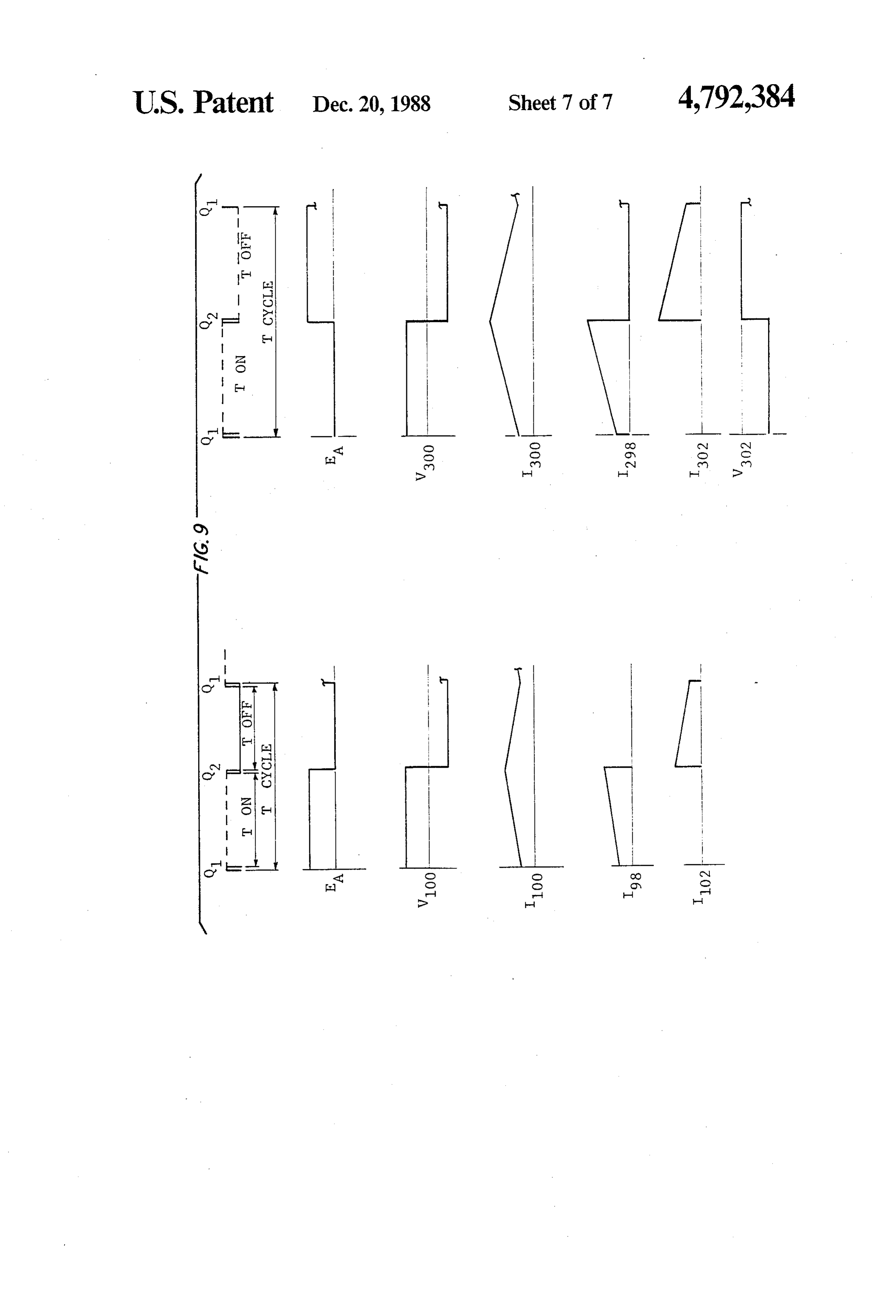
neous but are nearly so. The curves as drawn to approx 35 FIG. 9 summarizes several of the voltages and cur imate a perfect switch having instantaneous response, rents in the first conduit for the buck and boost regula but as will be realized, there is some small slope which tors. The cycle for the buck regulator T (Tc=Tcycle) has been eliminated for clarity. includes a period Ton during which the thyristor 98 Once the thyristor 98 begins conducting, the thyristor (switch) is in the "on' position and conducting and a 98 will conduct until the thyristor is made nonconduct period of time Toff during which the thyristor 98 is not ing. For the thyristor 98 to conduct current intermit conducting. Because the cycle time T is very great tently, the thyristor must stop carrying current. Ac compared to the pulse time it takes for the thyristor to cordingly, a second circuit 92 is provided to turn off the turn off when the pulse Q2 arrives at thyristor 116, the thyristor. This process is referred to as commutation. pulses Q and Q2 are shown as spikes coinciding with Commutation is begun by sending a control waveform 45 the on and off period for the thyristor 98. When the Q2 to the gate of thyristor 116 and causing a positive thyristor 98 is on, point A has a voltage EA which is voltage to exist between the gate and the cathode. The equal to the voltage Ef neglecting any small circuit voltage across the capacitor through the thyristor 116 is losses that might exist. When the thyristor switch 98 is positive and as a result of the control waveform Q2, a off, point A has a voltage EA which is equal to zero pulse of current I116 begins to flow as shown in FIG. 8. 50 (EA=0). The current I100 is increasing during the period The time scale for these waveforms is very expanded of time the switch is on and is decreasing during the to show the approximate shape of the waveform. In period of time the switch98 is off. The current 100 is the actual operation these waveforms appear almost as summation of the current I98 through the thyristor pulses. As the current I116 flows to the capacitor 120 the switch and the current I102. The current 102 is zero voltage V120 at point C decreases rapidly from the posi 55 during the period of time that the thyristor switch 98 is tive voltage Ef-c to a negative voltage -Ef-c. The on and is decreasing from some preselected value dur components in the second circuit such as the diode 118 ing the period of time when the switch is off. The cur and the inductor 122 are sized such that the capacitor rent I98 through the thyristor switch 98 is increasing will fully charge in a reverse polarity from the polarity during the on period and is decreasing from its maxi that existed at a time just before Q2. Thus, the circuit mum value during the off period. As can be seen, the rings around upon itself, fully charging the capacitor pattern for the current I.00 is one of developing a triang before the capacitor 120 begins to discharge through ular current where the rising portion is being carried by the diode 118. As the capacitor discharges, a current I is the switch 98 and the falling portion is being carried by generated. I118 is the commutation current is generated. the diode 102.
As the pulse of current I118 comes out of the capacitor 65 The voltage V 100 across the inductor is equal to the through diode 118 and moves toward point A, the cur inductance multiplied by the first derivative of the cur rent I98 goes to zero. One way describing the commuta rent with respect to time (V100=Ind-di/dt). The voltage tion is the current flowing from the fuel cell to the first drop is positive during the period of time when the
Page 15
switch is on. The voltage drop is equal to the voltage at with reverse polarity, a buck current flows and forces point A minus the voltage across the load. As can be the current through the switch thyristor 98, 298 to zero seen, the positive voltage is less than the voltage sup with the excess current flowing back into the capacitor plied by the fuel cell. The voltage drop V100 across the and the rest going to replace the output current of the inductor 100 is negative during the period of time when thyristor. Thus, the commutation circuits are the same the switch is off being equal to the negative of the load in both the buck regulator and the boost regulator. voltage. FIGS. 5 and 7 shows an improved design of the buck In summary we have a switch means which is the regulator and the boost regulator includes the two im thyristor 98, a means to resist changes in current provements mentioned earlier. The first improvement is through the primary circuit which is the inductor 100 10 a resistor for the current to charge the capacitor and a means to maintain the current flowing in the 120,320. This enables an operator to be sure that suffi means to resist changes in current which is the diode cient charge exists on the capacitor for the capacitor to 102. The second circuit 92 is a means to turn off the switch means by generating a current pulse that is provide a source of current for commutation. In cases greater than the current flowing through the means to 15 basic designresistor where the is not employed as is shown in the of the buck regulator in FIG. 4, the mi resist changes in current, inductor 100. crocomputer might be programmed to supply an initial The boost regulator works in a similar fashion to the charge buck regulator but, instead of the voltage being lower on the tocapacitor the capacitor to ensure that a sufficient charge than the source (the fuel cell voltage), the voltage is will be realized, theexists during start-up operation. As concern for the initial charge on the higher as a result of the orientation of the components. 20 capacitor is a concern during start-up operations but is The commutation or second circuit 292 for the boost regulator works in the same fashion as the commutation notThe once either regulator is running. second improvement to both the buck regulator circuit described above for the buck regulator. and the boost regulator is replacing the diode 118,318 in As with the buck regulator, the pulse signals Q1 and the commutation circuit with a thyristor 118,318 . In Q2 to the first thyristor switch 298 and the second thy 25 ristor switch 318 determine the period during which the both the buck regulator and the boost regulator shown thyristor 298 conducts and the period during which the in FIG. 5 and FIG. 7, the control signal Q2 causes the thyristor switch 98 does not conduct. The voltage Ea at capacitor to ring and charge before it can discharge into point A is pulled to ground (Ea-0) during the period of the diode. Thus, before you actually turn the current off time the thyristor switch 298 is "on' or conducting. The 30 through the switch thyristor 98,298, you must wait for thyristor 298 acts as a short circuit. The voltage Ea at the capacitor to charge. By replacing the diode with a point A is equal to the voltage Efe of the fuel cell source second thyristor 128,328 in you can initial the charging action earlier, in fact right after the signal Q1, have the plus the voltage across the inductor V300 (i.e., Ea=Efe. capacitor --Ind.di/dt). Although the voltage across the inductor already charged so that it waits for a gate 300 is negative during the period when the switch is in 35 signal Q3 to the third thyristor. As soon as the gate the on position, the voltages EA at point A is zero when signal Q3 reaches the thyristor Q3, the thyristor dis you turn the switch on. Thus the voltage across V300 is charges the capacitor and it enables you to save, for as shown, staring negative when the switch is on and example, a hundred microseconds resulting in a finer going positive when the switch is off. The current I300 control of the current through the direct current con through the inductor 300 increases during the period of 40 verter. If only a diode D2 is in the circuit, than as soon time when the switch is on and decreases during the as the capacitor reverses its polarity and reaches a full period of time the switch off. The voltage V302 across charge the capacitor will discharge through the diode. the diode in the first circuit is negative and is equal to As will be realized the direct current converter may the voltage of the electrochemical cell Vload because the consist of a plurality of boost regulators or buck regula diode 302 is blocking the flow of current through the 45 tors extending in parallel with each other between the electrochemical cell. Thus, the current is being shunted fuel cell and the electrochemical cells. This will result in through the first thyristor switch 298 with the result reduced probability for AC ripple in the electochemical that the current 302 flowing through the diode is equal cell when using a boost regulator. As will be appreci to the current Iload through the electrochemical cell is ated, AC ripple is to be avoided if possible in electro discontinuous. Thus, the inductor 300 in the boost regu 50 chemical cells.
lator acts as an intermediate storage of electrical energy Although the invention has been shown and de because the output voltage is greater than the input scribed with respect to detailed embodiments thereof, it voltage. In the buck regulator the inductor 100 acts as a should be understood by those skilled in the the art that filler to provide a continuous source of current to the various changes in form and detail thereof may be made electrochemical cell. In summary, the buck regulator 55 without departing from the spirit and the scope of the has a discontinuous source of current resulting in a claimed invention.
continuous output of current and in the boost regulator We claim:
the source of current is continuous and the output cur 1. An apparatus for carrying out an electrochemical rent is discontinuous. This continuous current may be a process which comprises:
source of AC ripple in the electrolysis cell by placing a 60 an electrochemical electrolysis cell which uses input plurality of boost regulators in parallel, this effect will electrical power at a first voltage and a first current be decreased. to produce a chemical product and hydrogen; The second commutation circuit in the boost regula at least one fuel cell which utilizes hydrogen to pro tor and the buck regulator work the same in both cir duce output electrical power at a second voltage cuits. In both circuits you gate the commutation thy 65 which is independent of the voltage of the electro ristor 116,316 by producing a pulse of current Q2 from chemical cell and a second current; microcomputer. As a result of the discharge of the ca means for supplying the hydrogen produced by the pacitor 120,320 and the rerecharging of the capacitor electrolysis cell to the fuel cell for consumption of
Page 16
at least a portion of the hydrogen by the fuel cell; 8. The invention as claimed in claim 7 wherein said and, regulator means is a bucking regulator having a first regulator means responsive to the power produced circuit and a second circuit, the first circuit having a by the fuel cell and to the hydrogen available to the first leg extending between the fuel cell and the electrol fuel cell for supplying output power received from 5 ysis cell and a second leg extending between the fuel the fuel cell as input power at the first voltage to cell and the electrolysis cell, wherein the first leg in the electrochemical cell, said means being electri cludes cally connected to the fuel cell and the electro said first gated switch, wherein said first gated switch chemical cell and said means employing a direct is a first thyristor having an anode and a cathode, current converter having gated switch means O said inductor wherein the inductor is connected to which intermittently passes current for regulating the cathode of the first thyristor and in series with the electrical power received from the fuel cell by the first thyristor between the first thyristor and intermittently flowing current between the fuel cell the electrolysis cell, and and the electrolysis cell through the gated switch 15 said means to enable the flow of current to the elec means to adjust the current and voltage supplied by trolysis cell, wherein said means to enable the flow the fuel cell so that the voltage change across said of current is a second diode having a cathode and regulator means is equal to the different between an anode, the diode being connected to a point the first voltage and the second voltage. between the first thyristor and the inductor in the 2. The apparatus as claimed in claim 1 wherein the 20 first leg, the diode being connected to the second electrochemical cell is a first source of hydrogen and leg such that the cathode of the second diode is wherein the apparatus includes a second source of hy wherein joined to the cathode of the first thyristor; drogen for supplying additional hydrogen to the fuel creating the second circuit includes the pulse means for a current, the second circuit including cell. a first leg having a third parallel diode extending in 3. The apparatus as claimed in claim 1 wherein the 25 parallel across the first thyristor of the first cir fuel cell supplies a portion of the power to the electrical cuit, the anode of the parallel diode being con chemical cell and wherein the apparatus further in nected to the cathode of the first thyristor for cludes means for supplying additional power to the conducting a portion of the current pulse to said electrochemical cell. capacitor, 4. The apparatus as claimed in claim 3 wherein the 30 a second leg extending in parallel across the first fuel cell has a schedule of desired operating voltages thyristor, the second leg having said second and wherein the fuel cell includes a means for control gated switch means, said second switch means ling the fuel cell voltage such that the voltage of the fuel being a second thyristor in series with said first cell lies within said schedule of desired operating volt diode connected to said capacitor, the cathode ages. 35 side of the first diode being connected to the 5. The apparatus as claimed in claim 4 wherein said cathode side of the first thyristor and the anode gated switch means responsive to a gate signal which side of the second thyristor being connected to has a conducting position and a nonconducting position the anode side of the first thyristor, and and wherein said regulator means includes an inductor a third leg connected in parallel from the anode connected to said gated switch means for resisting side of the first thyristor to the cathode side of changes in current through the inductor and generating the second thyristor, the third leg including said a voltage change across the inductor, wherein said reg capacitor and an second inductor, the capacitor ulator means includes pulse means for creating a current having one side connected to the anode side of pulse to deemergize said gated switch means, said pulse the first thyristor and a second side connected to means being connected to the gated switch means at a 45 the inductor and through the inductor to the point between the gated switch means and the inductor, cathode side of the second thyristor. and includes means to enable the flow of current to the 9. A method for operating a first electrochemical fuel electrolysis cell during the period of time said switch is cell in combination with a second electrochemical elec in the nonconducting position through said inductor trolysis cell, the fuel cell consuming hydrogen to pro and to oppose the diversion of the flow of current from 50 duce electrical energy and having a voltage characteris the electrolysis cell to ground through a point between tic that decreases with current and the electrolysis cell said gated switch means and said inductor. having a voltage characteristic that increases with cur 6. The apparatus as claimed in claim 5 wherein the rent and producing both hydrogen and a chemical prod gated switch means is a first gated switch means and uct as a result of the consumption of electrical energy, wherein said pulse means includes a second gated 55 which comprises:
switch means responsive to a second gate signal and a operating the electrolysis cell at a first current and at means for developing a current pulse which is in series a first voltage to produce hydrogen and a chemical with said second gated switch means, wherein said product through electrolysis; second gated switch means passes a current to the supplying the hydrogen produced by the electrolysis means for developing a current pulse in response to a 60 cell to the fuel cell;
gate signal. operating the fuel cell to consume hydrogen and 7. The invention as claimed in claim 6 wherein said produce power at a second current and at a second means for developing a current pulse includes a capaci voltage which is independent of the voltage of the tor for storing charge and further includes a first diode electrochemical cell;
connected to the capacitor and the first gated switch 65 sensing the power output of the fuel cell; means which conducts the current pulse to the first converting the power output of the fuel cell at the gated switch as the capacitor discharges through the second current and the second voltage to a third diode. current and an output voltage in a direct current
Page 17
converter responsive to the output power of the converter during the established duty cycle of the con fuel cell and to the hydrogen available to the fuel veter.
cell, the direct current converter having a gated 11. The method of operating the combined cells of switch means for passing electrical current from 5 claim 10 wherein the direct current converter is a cur the fuel cell intermittently through the gated rent regulator and wherein the step of flowing current switch means of the direct current converter to the intermittently between the fuel cell and the electrolysis electrochemical cell to enable the direct current includes the step of forming a current pulse and bucking the current converter to establish a voltage change through the switch means pulse against the current through the gated converter to match the output voltage of the direct 10 pass current and to cause the gated switch means to not current converter to the first voltage of the elec between the fuel thereby interrupt the flow of current cell and the electrochemical cell.
trolysis cell; and 12. The method of operating the combined cells of supplying the third current to the electrolysis cell to claim 10 wherein the step of sensing the power output provide at least a portion of the current required to of the fuel cell includes the step of sensing the flow of produce hydrogen and the chemical product with 5 hydrogen to the fuel cell and producing a signal indica said first current. tive of power output of the fuel cell. 10. The method of operating the combined cells of 13. The method of operating the combined electro claim 9 wherein the direct current converter has a duty chemical cells of claims 9, 10 or 12 which includes the cycle during which the gated switch means is conduct steps of establishing an upper limit and a lower limit of ing to provide for the intermittent flow of current 20 the voltage of the fuel cell and adjusting the power through the direct current converter, the duty cycle output of the fuel cell to maintain the voltage between being variable wherein the method further includes the the14.upper The limit and the lower limit.
method of operating the combined electro step of establishing a desired third current and includes chemical cells of claim 12 wherein the power required the step of establishing a duty cycle as a function of the 25 to operate the electrolysis cell at a first current and a desired third current, the actual third current and the first voltage is greater than the power supplied by the power output of the fuel cell, and wherein the step of fuel cell wherein the method further includes the step of converting the power output in the direct current con connecting the output of the fuel cell in parallel with a verter includes the step of flowing current intermit source of power to supplement the power supplied by tently between the fuel cell and the electrolysis cell 30 the fuel cell to the electrolysis cell. through the gated switch means of the direct current it k 2 k is
Provenance
- Collection
- Cited prior art
- Original PDF
- patentimages.storage.googleapis.com →
- Filed
- 1987-03-20
- Pages
- 17
- Method
- pdftotext (the PDF's own text layer) + pdftoppm 300dpi page scans
- Source
- Google Patents bibliographic record
- Granted
- 1988-12-20
- Inventors
- Alexander H. Levy; Kenneth Lipman; United Technologies Corp
- Transcribed from
- patentimages.storage.googleapis.com →