patent · US3716969
Continuous moving layer type adsorption device
20 February 1973
Page 1 — bibliographic record
United States Patent (19) 11, 3,716,969 Maeda (45) Feb. 20, 1973
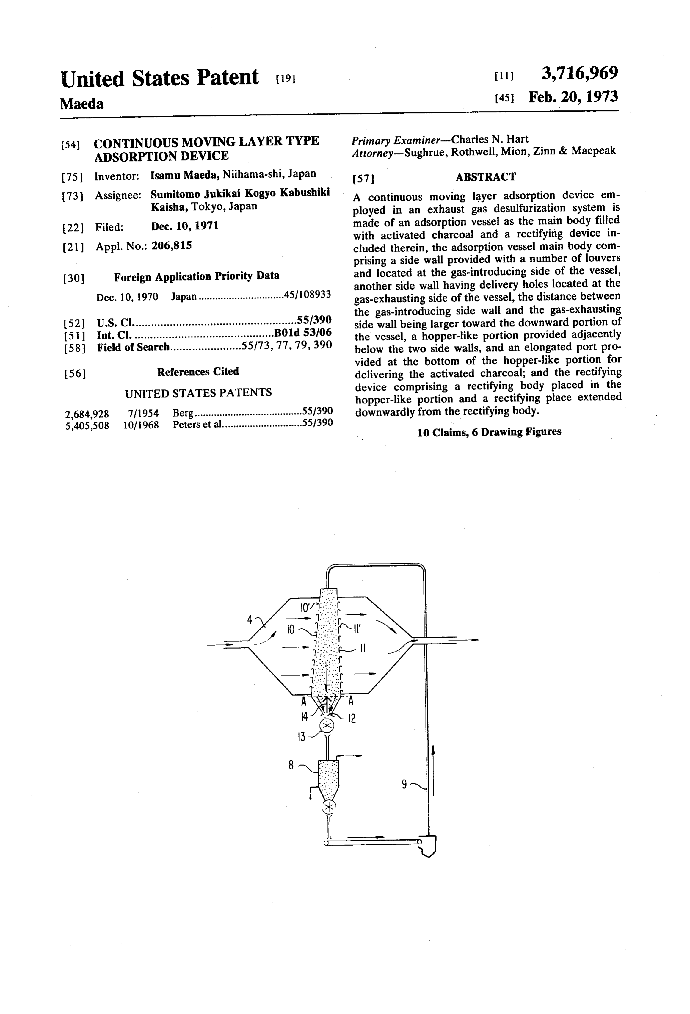
54) CONTINUOUS MOVING LAYERTYPE Primary Examiner-Charles N. Hart ADSORPTON DEVICE Attorney-Sughrue, Rothwell, Mion, Zinn & Macpeak (75 Inventor: Isamu Maeda, Niihama-shi, Japan 57 ABSTRACT 73 Assignee: Sumitomo Jukikai Kogyo Kabushiki A continuous moving layer adsorption device em Kaisha, Tokyo, Japan ployed in an exhaust gas desulfurization system is 22 Filed: Dec. 10, 1971 made of an adsorption vessel as the main body filled with activated charcoal and a rectifying device in (21) Appl. No.: 206,815 cluded therein, the adsorption vessel main body com prising a side wall provided with a number of louvers 30 Foreign Application Priority Data and located at the gas-introducing side of the vessel, another side wall having delivery holes located at the
Dec. 10, 1970 Japan...............................45/108933 gas-exhausting side of the vessel, the distance between the gas-introducing side wall and the gas-exhausting
I52) U.S.C.....................................................55/390 side wall being larger toward the downward portion of 51) Int. Cl. ............................................. B01d 53/06 the vessel, a hopper-like portion provided adjacently 58 Field of Search.......................55/73, 77, 79,390 below the two side walls, and an elongated port pro vided at the bottom of the hopper-like portion for 56) References Cited delivering the activated charcoal; and the rectifying UNITED STATES PATENTS device comprising a rectifying body placed in the hopper-like portion and a rectifying place extended 2,684,928 7|1954 Berg.......................................55/390 downwardly from the rectifying body. 5,405,508 10/1968 Peters et al.............................55/390 10 Claims, 6 Drawing Figures
Page 2
Drawing sheet — no readable text.
Page 3
Drawing sheet — no readable text.
Page 4
CONTINUOUS MOWINGLAYERTYPE phenomenon or suspension phenomenon does not oc
The above described and other objects of the present
BACKGROUND OF THE INVENTION invention can be achieved by an improved construction 1. Field of the Invention of the adsorption device comprising a main body of an This invention generally relates to a desulfurization adsorption vessel filled with activated charcoal and a system wherein exhaust gas caused by combustion is rectifying device, said main body further comprising a passed through an adsorption vessel filled with ac side wall provided with a number of louvers and tivated charcoal and the SO, gas contained in the ex 10 located at the gas-introducing side of the vessel, haust gas is adsorbed into the charcoal, and more par another side wall having delivery holes located at the ticularly to a particular construction of the adsorption gas-exhausting side of the vessel, the distance between vessel which enables desulfurization to be performed the gas-introducing side wall and the gas-exhausting continuously. side wall being made larger toward the downward por
tion of the vessel, a hopper-like portion provided ad
In the case where the SO, gas is adsorbed into the jacently below said two side walls, and an elongated charcoal filling of the adsorption vessel, it is natural port provided at the bottom of said hopper-like portion that there is a limitation in the adsorbing ability of the for delivering said activated charcoal; and said rectify activated charcoal. Thus, as the charcoal approaches ing device comprising a rectifying body placed in said its limitation of adsorption, it must be replaced by new 20 hopper-like portion and extended along the whole material. length of the elongated delivery port, said rectifying However, it is desirable that the desulfurization be body being formed into a triangular cross-section hav operated continuously without interruption, thus main ing two downwardly tapered side surfaces and a ridge taining a constant adsorption capability because the line at the top, and a rectifying plate extended desulfurization device is ordinarily directly coupled to 25 downwardly from the rectifying body vertically. an exhaust gas source, such as a boiler. In other words, The nature, principle, and utility of the present in the activated charcoal must be replaced continuously, vention will be more clearly understood from the fol for instance, in such a manner that the deteriorated lowing detailed description of the invention when read charcoal be continuously removed from the lower por in conjunction with the accompanying drawings. tion of the adsorption vessel, regenerated in the sub 30 sequent expelling and cooling tanks, and circulated to BRIEF DESCRIPTION OF THE DRAWINGS the inlet port of the adsorption vessel. In the drawings:
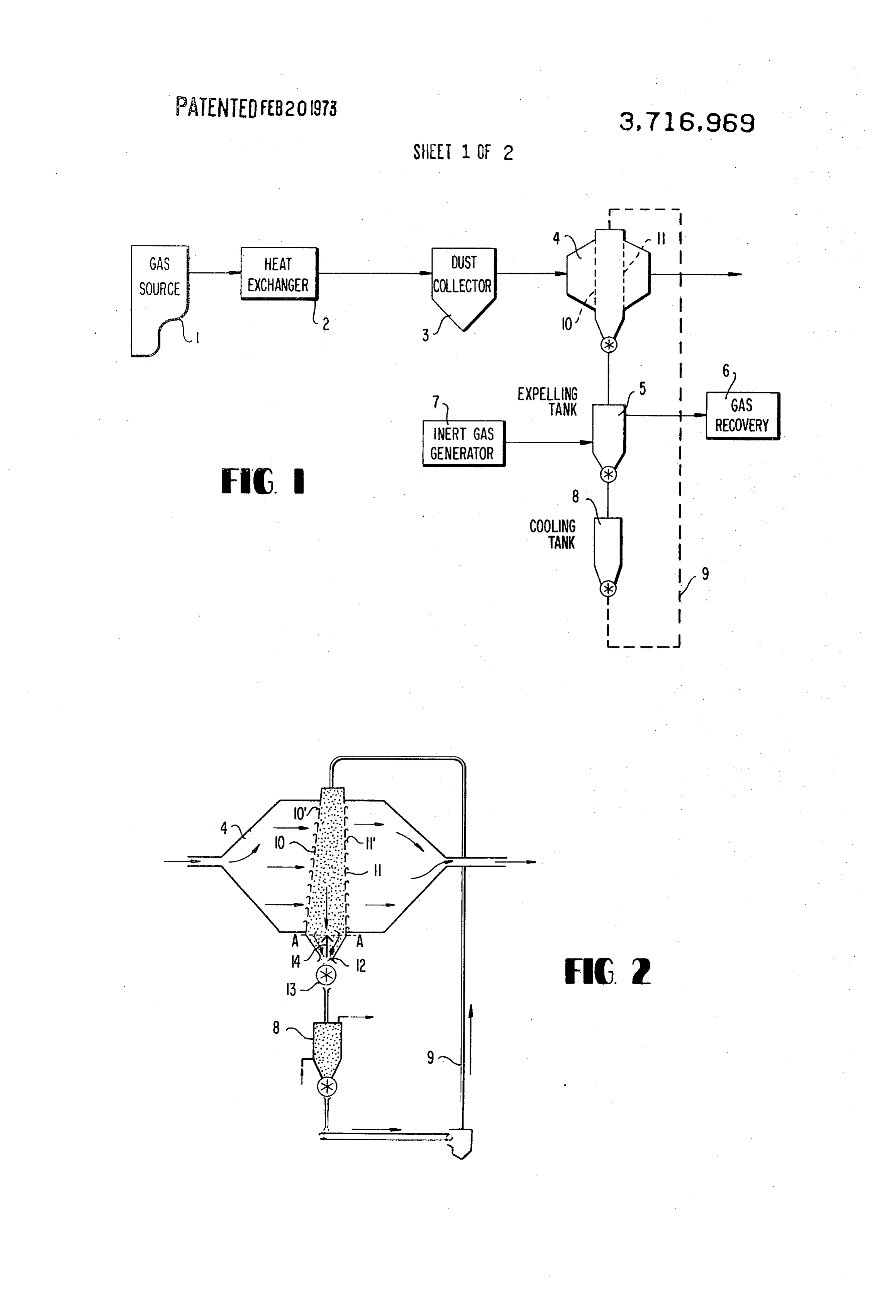
Heretofore, the adsorption vessel has been so con FIG. 1 is a flow sheet showing the organization of the structed so that a box-like vessel is at its lower portion desulfurization narrowed into a hopper-like configuration and an ex 35 according to thesystem present in which an adsorption vessel invention is to be used;
haust valve is provided at the narrowed portion. Both sides of the box-like vessel through which the gas is in of an adsorption vessel ofprofile FIG. 2 is a schematic the view, partly in section, present invention;
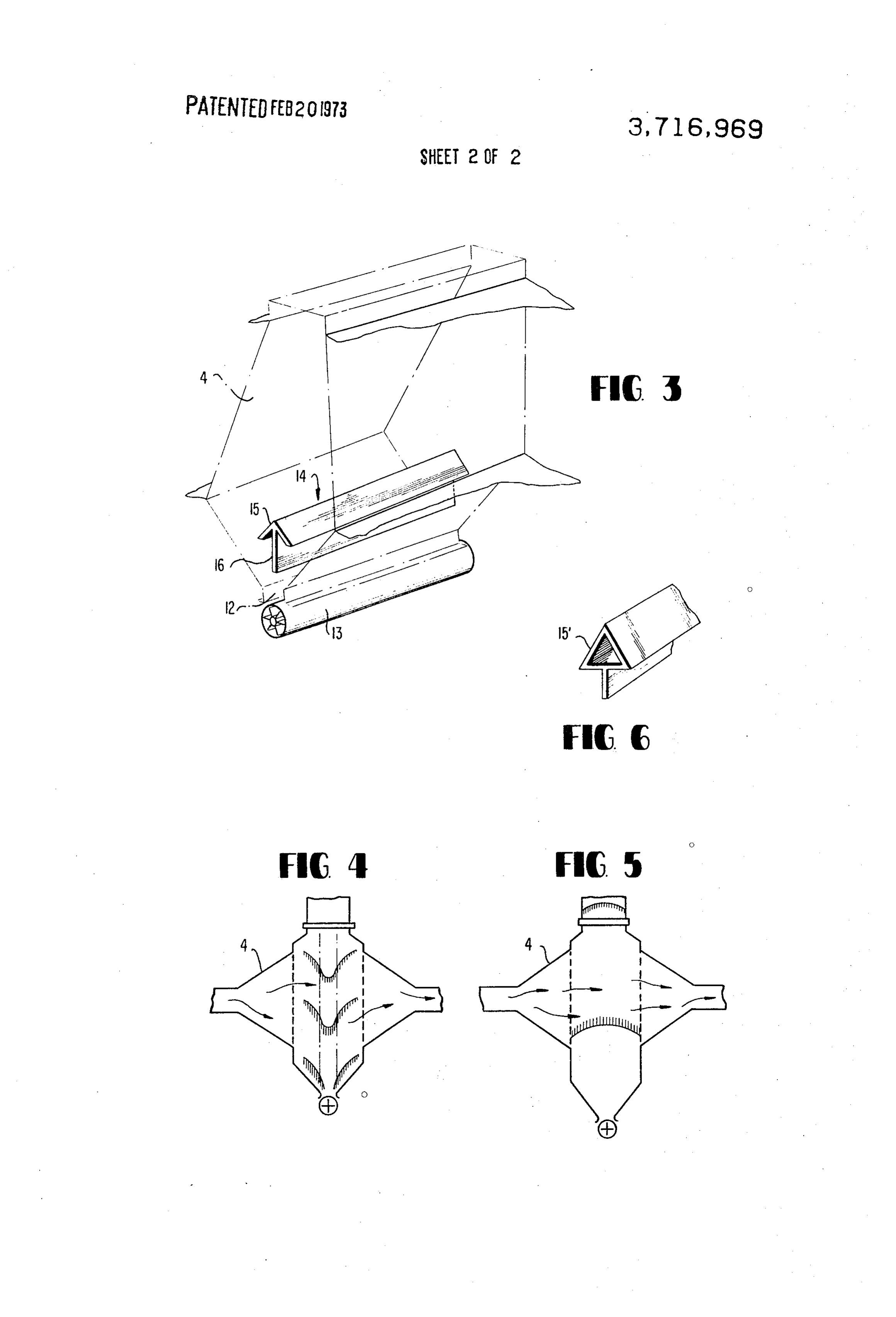
troduced and delivered are made of a porous plate or a FIG. 3 is a perspective view of the adsorption vessel mesh-plate. Because of the above-described construc shown in FIG. 2;
tion of the conventional adsorption vessel, however, 40
FIG. 4 is a view for explaining the center-dropping there have been found the drawbacks of causing a phenomenon;
center-dropping phenomenon or suspension FIG. 5 is a view for explaining the suspension phenomenon in the filler layers inside of the adsorption phenomenon; and vessel.
Herein, the center-dropping phenomenon is defined 45 FIG. 6 is a perspective view showing an example of a to be a phenomenon wherein the centrally located por rectifying device employed in the adsorption vessel ac tion in the layers of the activated charcoal just above cording to the present invention. the exhausting port falls down prematurely, and the DETAILED DESCRIPTION OF THE INVENTION suspension phenomenon is defined to be a phenomenon wherein the activated charcoal filled in 50 Detailed Description of the Drawings side of the adsorption vessel is suspended in a crust-like configuration caused by a lateral compressive force, theReferring now to FIG. 1 showing the organization of desulfurization system in which the adsorption ves both of which will be described hereinafter in more detail. sel according to the present invention is to be em 55 ployed, there is indicated that the combustion exhaust
SUMMARY OF THE INVENTION gas from a source i, such as a boiler is passed through a A primary object of the present invention is to pro heat exchanger 2 so that the exhaust gas is adjusted as vide an adsorption vessel wherein the above described for gas the temperature suitable for the adsorption of SO (about 120°C). The gas is thereafter passed through drawbacks can be substantially eliminated. 60
Another object of the present invention is to provide a dust collector 3 and then introduced into an adsorp an adsorption vessel containing continuously moving tion vessel 4. The activated charcoal saturated by the layers of activated charcoal, whereby the charcoal can SO, gas is supplied to an expelling tank.5 to expel the be replaced continuously. SO, gas adsorbed in the adsorption vessel 4 and then A further object of the present invention is to pro 65 passed to a cooling tank 8. In the expelling tank 5, an vide an adsorption vessel adapted to be employed in a inert gas obtained from an inert gas generating device 7 desulfurization system of a continuously operable type and heated to a temperature adapted to expel SO, gas wherein, the above described center-dropping from the activated charcoal (in a range of from 350°C
Page 5
to 400°C) is circulated. The SO, gas thus expelled from dustrial application, however, the rectangular cross the charcoal is sent out of the tank 5 together with the section shown in FIGS. 2 and 3 is preferable. Further inert gas into an SO, gas recovering device 6 provided more, although the delivery side wall 11 of the charcoal in the subsequent stage. The above mentioned inert gas filled chamber has also been indicated as louvered, this generating device 7 is composed of an inert gas may be constructed into a wall having mesh-like holes generating furnace, temperature regulating device, and or into a porous plate or any other configuration a supplying fan. The activated charcoal from which the adapted for the purpose.
A rectifying device 14 is then provided within the adsorbed SO, gas has been expelled as described above is then sent to a cooling tank 8 provided in the follow 10 hopper-like portion 12 in such a manner that the device ing stage of the SO, gas expelling tank 5. Numeral 9 14 is extended along the whole length of the exit port designates a lifting conveyor made of, for instance, a like12. The rectifying device 14 further comprises a roof triangular rectifying body 15 and a rectifying plate combination of a conveyor and a bucket elevator and 16 suspended sending back the thus regenerated activated charcoal vertically downwardly from the rectify from the cooling tank 8 to the adsorption vessel 4. ing body 15. In the indicated example, the longitudinal
In FIGS. 2 and 3, there is indicated a construction of axis of the exit port 12 and hence the extended the adsorption vessel 4. At the central portion of the direction of the rectifying device 14 is perpendicular to adsorption vessel 4, there is provided a chamber filled the flowing direction of the exhaust gas. with the activated charcoal, and both side walls 10 and The above described taper of the side walls of the 11 of which are made in the form of louver boards. The 20 charcoal filled chamber is so selected that an angle of gas exhausted from a combustion chamber is in from 6 to 20' is formed between the two side walls. troduced into and delivered from the chamber bound When the angle is enlarged more than 20, the required by the walls 10 and 11 and filled with the activated amount of activated charcoal is too much and the size charcoal as indicated by the arrow marks in FIG. 2. 25 of the hopper-like portion and the rotary feeder must Herein, it should be noted that the louvered wall 10 at be enlarged. Furthermore, the difference in the the introduction side of the chamber is tapered in such dropping velocities of the activated charcoal layers becomes exceedingly great, and the effect of compen a manner that the distance between the wall 10 and the delivering side wall 11 is enlarged toward the sating the lowering of the adsorption efficiency cannot downward portion of the chamber, and for this reason, be sufficient. For this reason, the above described taper the layers of the activated charcoal filled inside of the 30 angle is more preferably selected in a range of from 7 chamber are made thicker toward the downward por to 12, and at best 9-10°. The rectifying body 15 is provided within the hopper-like portion of the charcoal tion of the chamber when the thicknesses are measured along the flow of the gas. filled chamber, and it is preferable that the upper ridge The louvered walls 10 and 11 are provided with a of the rectifying body 15 is aligned with a line A-A in number of louver pieces 10' and 11", respectively, the 35 hopper-like
FIG. 2 connecting the upper flexing points of the portion. The rectifying body 15 may also outwardly directing edges of which are curved for smoothening the stream of the gas flow and also for stif be made in the form of a triangular body 15" shown in fening the louver pieces. Although the introducing side FIG. 6, and an angle formed by the two side surfaces of of the wall 10 is indicated to be tapered slightly, while 40 the triangular body 15 or 15" is selected at a range of the delivery side wall 11 is extended vertically, the rela from 30 to 60°.
tion may also be reversed, such that the introducing The length of the bottom side of the triangular body side wall 10 is extended vertically and the delivery side 15 or 15" is preferably selected to a value larger than wall 11 is tapered slightly. Likewise, both of the walls the width of the exit port 12, and the tapered angles of 10 and 11 may be slightly tapered so that the distance 45 both sides of the triangular body are determined to be between these walls is enlarged toward downwardly. substantially equal to the tapered angles of both sides The lower portion of the chamber filled with the char of the hopper-like portion. That is, both sides of the tri coal, which is adjacent downwardly to the side walls 10 angular rectifying body 15, 15' and the both sides of and 11 is narrowed or reduced in its width in a hopper the hopper-like portion are determined to be substan like configuration having an elongated exit port 12 with 50 tially parallel with each other, so that the descending the longitudinal axis thereof extending along the whole velocities of the charcoal in both sides of the rectifying device 14 within the hopper-like portion are made sub length of the chamber, in a direction vertical to the stantially plane of the drawing, and a charcoal remover 13 of, for equal. The height of the rectifying plate 16 is instance, a rotary feeder type is provided at the exit 55 selected to be sufficient for being extended to a posi port 12. tion where the downwardly streaming charcoal at both Although in FIGS. 2 and 3, the exit port 12 is in sides of the rectifying body 15, 15' are directed sub dicated to be opening downwardly with the longitu stantially downwardly. In addition, the rectifying plate dinal axis thereof extending at a right angle against the 16 should not always be just underneath the upper edge flowing direction of the gas, the longitudinal axis of the of the triangular configuration, but may be displaced to exit port 12 may also be extended along the flowing 60 either side nearer to the introduction side or the direction of the gas when such a construction is suitable delivery side of the gas flow, provided the displacement to the configuration of the charcoal filled chamber. of the rectifying plate 16 does not interfere the flow of Although the charcoal filled chamber has been ex the charcoal at that portion.
plained for the case where the cross section thereof cut 65 The activated charcoal employed in the present in along the flow line of the gas is rectangular, this may be vention may be of powdery structure or pulverized of square, oval, or any other configuration, if such a (granular) structure, and the adsorption device accord construction adapts the required conditions. In an in ing to the present invention can be employed in either
Page 6
S 6 of the cases where the charcoal is moved downwardly pressure loss caused in the gas flow by the existence of without intermission or where it is descended intermit the adsorption vessel can be decreased by preventing tently at a predetermined amount for each time. the clogging of gaps between each of the granules of The operation and advantageous effects of the the activated charcoal by the dust in the exhaust gas. In present invention will now be described. addition, because of the uniform and constant circula Since the chamber filled with the charcoal is so con tion of the activated charcoal, the consumption of the structed that at least one of the side walls is tapered, the charcoal can be substantially reduced. Thus, it is ap activated charcoal fills the inside of the chamber in parent that the continuous operation of the adsorption such a manner that the thickness thereof measured 10 device can be advantageously carried out with the ac along the flow direction of the gas is thicker in the tivated charcoal being regeneratively circulated back lower portion of the chamber then in the upper portion. to Although the inlet port of the adsorption vessel.
That is, the profile view in the section of the charcoal described inthe present invention has been sufficiently filled chamber is made into a frustoconical configura included therein,foregoing the specification and examples tion. Accordingly, the laminar pressure acting between 15 changes and modifications mayapparent it is readily
that various made by those each layer of the charcoal causes a lowering force for skilled in the art without departing from the spirit and descending the charcoal, whereby the downward scope thereof.
movement of the charcoal can be carried out smoothly. What I claim is:
In other words, the above described suspension 1. A continuous moving layer type adsorption device phenomenon can be prevented substantially, and the employed in a gas desulfurization system, comprising: possibility of causing mesh-clogging by dust in the ex a. an adsorption vessel main body filled with ac haust gas filling inside of the thus suspended charcoal tivated charcoal, and can be altogether eliminated. b. a rectifying device, said adsorption vessel main Furthermore, the charcoal loses its adsorption ability body further comprising: while it is moved from the upper portion to the lower 25 1. a side wall provided with a number of louvers portion of the charcoal filled chamber. However, in the and located at the gas-introducing side of the construction of the adsorption device according to the vessel, present invention, since the thickness of the chamber 2. another side wall having delivery holes located along the flowing direction of the gas is enlarged 30 at the gas-exhausting side of the vessel, the toward the downwardly portion, the above described distance between the gas-introducing side wall decrease of the adsorption ability of the charcoal can and the gas-exhausting side wall being made be compensated by the increase in the thickness of the larger toward the downward portion of the ves charcoal chamber. sel,
Likewise, because of the provision of the rectifying . . a hopper-like portion provided adjacently below body 15 or 15, the pressure of the charcoal layers 35 said two side walls, and located above the exit port 12 is borne by the two . . an elongated port provided at the bottom of said tapered surfaces of the rectifying body 15 or 15'., hopper-like portion for delivering said activated whereby the charcoal layers are along their whole sec charcoal, said rectifying device comprising: tional portions supported by the side surfaces of the 40 i. a rectifying body placed in said hopper-like hopper-like portion and the two tapered surfaces of the portion and extended along the whole length rectifying body, and the above described center of the elongated delivery port, said rectifying dropping phenomenon can be thereby prevented. The body being formed into a triangular cross-sec rectifying plate 16 is provided for eliminating the inter tion having two downwardly tapered side sur ference between the two downward streams of char 45 faces and a ridge line at the top, and coal created at both sides of the rectifying device 14, ii. a rectifying plate extended downwardly from and any malicious effect caused on one of the the rectifying body vertically. downward stream by the other downward stream of the 2. The adsorption device of claim 1, wherein the charcoal can be substantially eliminated. Thus the upper edge of each of the louvers of said side wall is downward stream of the charcoal can be exhausted 50 bent outwardly from the adsorption vessel filled with without any disturbance, even if the flow rates of the the activated charcoal.
two streams are different from each other. 3. The adsorption device of claim 1, wherein the Although the operation and advantageous effects of angle formed between the gas-introducing side wall and the present invention have been described 55 the gas-exhausting side wall of the adsorption vessel is hereinabove, a surprising fact in this invention is that in the range of from 6 to 20°.
the layers of the activated charcoal considered in a ver 4. The adsorption device of claim 1, wherein the tical plane parallel to the gas flow can be descended al angle formed between the gas-introducing side wall and together maintained in parallel. This fact was found the gas-exhausting side wall of the adsorption vessel is true after numerous experiments with the exhaust 60 in the range of from 7 to 12.
speed of the charcoal being varied in each of the ex 5. The adsorption device of claim i, wherein the periments. That is, all of the layers of the charcoal were rectifying body is provided in said hopper-like portion descended while the disposition of the layers was main in such a manner that the ridge line at the top of the tained as it was. Because of this fact, not only the above rectifying body is aligned with a line connecting the described center dropping phenomenon and the 65 upper flexing points of the hopper-like portion. suspension phenomenon can be completely prevented, 6. The adsorption device of claim 1, wherein the but also a uniform adsorption can be maintained apex angle formed between the two side surfaces of the throughout the adsorption vessel. Furthermore, the rectifying body is in the range of from 30° to 60.
Page 7
7. The adsorption device of claim 1, wherein the rectifying plate is extended downwardly to the point width of the bottom edge of the triangular cross-section where two streams of the activated charcoal divided by of the rectifying body is larger than the width of the the rectifying body are changed in their direction delivery port. downwardly toward the delivery port. 8. The adsorption device of claim 1, wherein the 10. The adsorption device of claim 1, wherein the tapered side surfaces of said rectifying body are sub angle formed between the gas-introducing side wall and stantially parallel with the tapered walls of said hopper the gas-exhausting side wall of the adsorption vessel is like portion, respectively. in the range of from 9 to 10.
9. The adsorption device of claim 1, wherein said
Provenance
- Collection
- Cited prior art
- Original PDF
- patentimages.storage.googleapis.com →
- Filed
- 1971-12-10
- Pages
- 7
- Method
- pdftotext (the PDF's own text layer) + pdftoppm 300dpi page scans
- Source
- Google Patents bibliographic record
- Granted
- 1973-02-20
- Inventors
- I Maeda; Sumitomo Heavy Industries Ltd
- Transcribed from
- patentimages.storage.googleapis.com →