patent · US4722661
Magnetic-drive centrifugal pump
2 February 1988
Page 1 — bibliographic record
United States Patent (19) 11) Patent Number: 4,722,661 Mizuno 45) Date of Patent: Feb. 2, 1988 54 MAGNETIC-DRIVE CENTRIFUGAL PUMP FOREIGN PATENT DOCUMENTS 75 Inventor: Motoshige Mizuno, Tokai, Japan 3337086 5/1985 Fed. Rep. of Germany .
(73) Assignee: NGK Insulators, Ltd., Aichi, Japan 59-180099 10/1984 Japan. (21) Appl. No.: 785,657 Primary Examiner-Abraham Hershkovitz Assistant Examiner-John T. Kwon
Attorney, Agent, or Firm-Parkhurst & Oliff
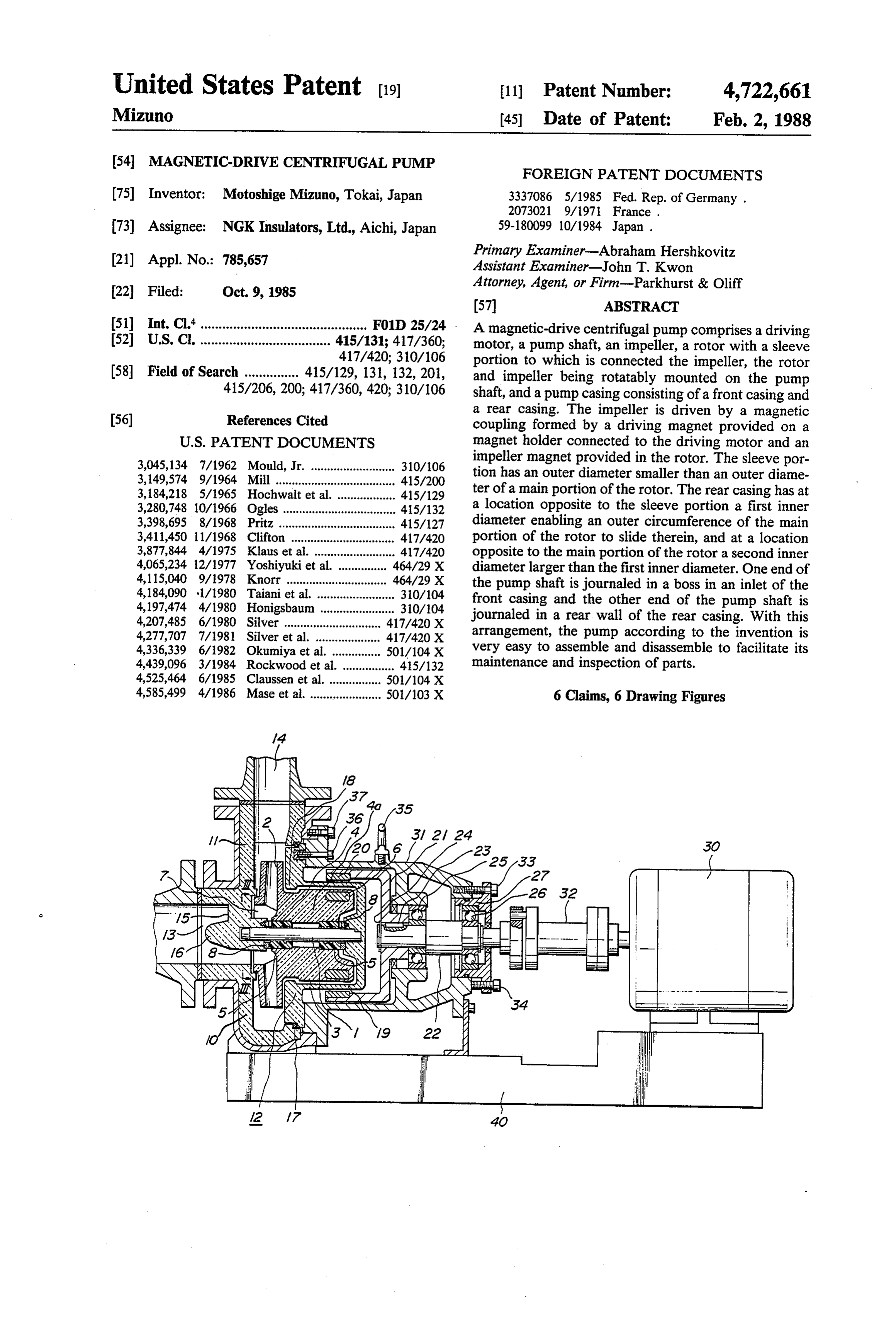
51) Int. Cl'.............................................. F01D 25/24 A magnetic-drive centrifugal pump comprises a driving 52 U.S. C. .................................... 415/131; 417/360; motor, a pump shaft, an impeller, a rotor with a sleeve 417/420; 310/106 portion to which is connected the impeller, the rotor 58 Field of Search ............... 415/129, 131, 132, 201, and impeller being rotatably mounted on the pump 415/206, 200; 417/360, 420; 310/106 shaft, and a pump casing consisting of a front casing and
a rear casing. The impeller is driven by a magnetic coupling formed by a driving magnet provided on a
3,045,134 7/1962 Mould, Jr. .......................... 310/106 impeller magnet provided in the rotor. The sleeve por 3,149,574 9/1964 Mill .................. ... 415/200 tion has an outer diameter smaller than an outer diame 3,184,218 5/1965 Hochwalt et al. ... 415/129 ter of a main portion of the rotor. The rear casing has at 3,280,748 10/1966 Ogles ....... ... 41.5/132 a location opposite to the sleeve portion a first inner 3,398,695 8/1968 Pritz ..... ... 415/127 diameter enabling an outer circumference of the main 3,411,450 11/1968 Clifton ..... ... 417/420 portion of the rotor to slide therein, and at a location 3,877,844 4/1975 Klaus et al. ...... ... 417/420 opposite to the main portion of the rotor a second inner 4,065,234 12/1977 Yoshiyuki et al. ............... 464/29 X diameter larger than the first inner diameter. One end of 4,115,040 9/1978 Knorr ............................... 464/29 X the pump shaft is journaled in a boss in an inlet of the 4,184,090 l/1980 Taiani et al. ..... ... 30/104 front casing and the other end of the pump shaft is 4,197,474 4/1980 Honigsbaum ... ... 310/104 journaled in a rear wall of the rear casing. With this 4,207,485 6/1980 Silver ............... ... 417/420 X 4,277,707 7/1981 Silver et al. ......... ... 417/420 X arrangement, the pump according to the invention is 4,336,339 6/1982 Okumiya et al. ... ... 501/104X very easy to assemble and disassemble to facilitate its 4,439,096 3/1984 Rockwood et al. ................ 415/132 maintenance and inspection of parts.
4,585,499 4/1986 Mase et al. ...................... 50/103 X 6 Claims, 6 Drawing Figures
Sits. s
Says
SNS
See
Page 2
Drawing sheet — no readable text.
Page 3
Drawing sheet — no readable text.
Page 4
Drawing sheet — no readable text.
Page 5
Drawing sheet — no readable text.
Page 6
Drawing sheet — no readable text.
Page 7
boss. As a result, such a great moment often damages
MAGNETC-DRIVE CENTRFUGAL PUMP the pump shaft or the rear casing. When the pump shaft
BACKGROUND OF THE INVENTION
and the rear casing are made of a ceramic material in order to improve their chemical corrosion-resistance,
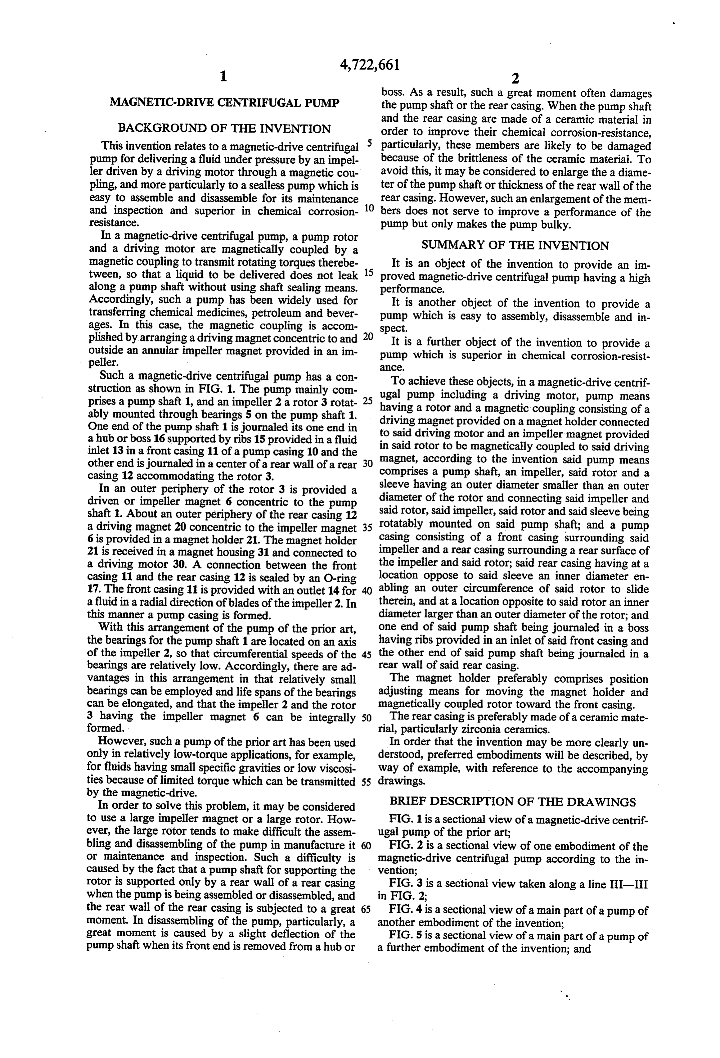
This invention relates to a magnetic-drive centrifugal particularly, these members are likely to be damaged pump for delivering a fluid under pressure by an impel because of the brittleness of the ceramic material. To ler driven by a driving motor through a magnetic cou avoid this, it may be considered to enlarge the a diame pling, and more particularly to a sealless pump which is ter of the pump shaft or thickness of the rear wall of the easy to assemble and disassemble for its maintenance rear casing. However, such an enlargement of the mem and inspection and superior in chemical corrosion 10 bers does not serve to improve a performance of the resistance. pump but only makes the pump bulky. In a magnetic-drive centrifugal pump, a pump rotor and a driving motor are magnetically coupled by a SUMMARY OF THE INVENTION magnetic coupling to transmit rotating torques therebe It is an object of the invention to provide an im tween, so that a liquid to be delivered does not leak 15 proved magnetic-drive centrifugal pump having a high along a pump shaft without using shaft sealing means. performance.
Accordingly, such a pump has been widely used for It is another object of the invention to provide a transferring chemical medicines, petroleum and bever pump which is easy to assembly, disassemble and in ages. In this case, the magnetic coupling is accom spect.
plished by arranging a driving magnet concentric to and 20 It is a further object of the invention to provide a outside an annular impeller magnet provided in an im pump which is superior in chemical corrosion-resist peller. alCe,
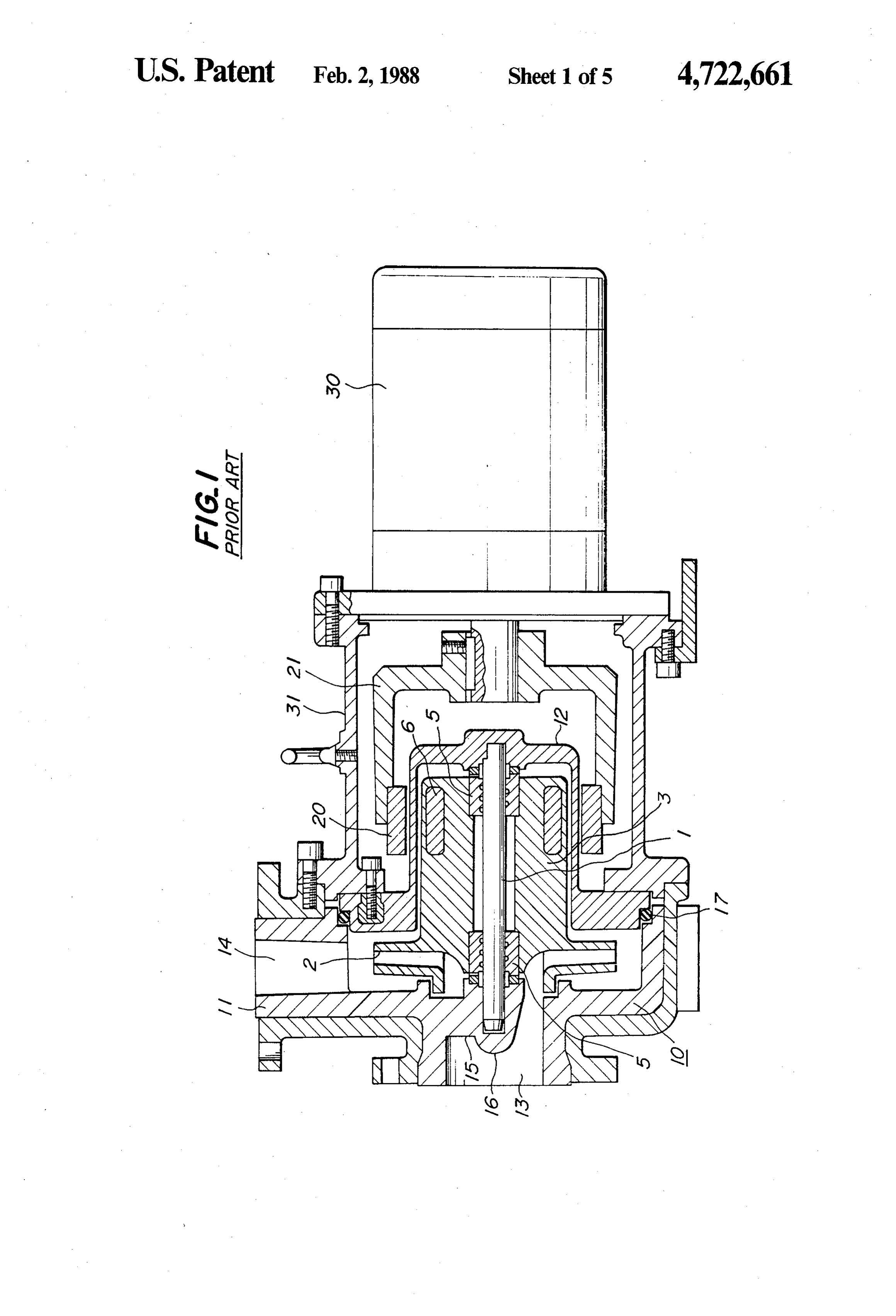
Such a magnetic-drive centrifugal pump has a con To achieve these objects, in a magnetic-drive centrif struction as shown in FIG. 1. The pump mainly com ugal prises a pump shaft 1, and an impeller 2 a rotor 3 rotat 25 havingpump including a driving motor, pump means ably mounted through bearings 5 on the pump shaft 1. driving magnetand a rotor a magnetic coupling consisting of a provided on a magnet holder connected
One end of the pump shaft 1 is journaled its one end in to said driving motor and an impeller magnet provided a hub or boss 16 supported by ribs 15 provided in a fluid in said rotor to be magnetically coupled to said driving inlet 13 in a front casing 11 of a pump casing 10 and the other end is journaled in a center of a rear wall of a rear 30 magnet, according to the invention said pump means comprises a pump shaft, an impeller, said rotor and a casing 12 accommodating the rotor 3.
In an outer periphery of the rotor 3 is provided a sleeve having an outer diameter smaller than an outer driven or impeller magnet 6 concentric to the pump diameter of the rotor and connecting said impeller and shaft 1. About an outer periphery of the rear casing 12 said rotor, said impeller, said rotor and said sleeve being a driving magnet 20 concentric to the impeller magnet 35 rotatably mounted on said pump shaft; and a pump 6 is provided in a magnet holder 21. The magnet holder casing consisting of a front casing surrounding said 21 is received in a magnet housing 31 and connected to impeller and a rear casing surrounding a rear surface of a driving motor 30. A connection between the front the impeller and said rotor; said rear casing having at a casing 11 and the rear casing 12 is sealed by an O-ring location oppose to said sleeve an inner diameter en 17. The front casing 11 is provided with an outlet 14 for abling an outer circumference of said rotor to slide a fluid in a radial direction of blades of the impeller 2. In therein, and at a location opposite to said rotor an inner this manner a pump casing is formed. diameter larger than an outer diameter of the rotor; and With this arrangement of the pump of the prior art, one end of said pump shaft being journaled in a boss the bearings for the pump shaft 1 are located on an axis having ribs provided in an inlet of said front casing and of the impeller 2, so that circumferential speeds of the 45 the other end of said pump shaft being journaled in a bearings are relatively low. Accordingly, there are ad rear wall of said rear casing.
vantages in this arrangement in that relatively small The magnet holder preferably comprises position bearings can be employed and life spans of the bearings adjusting means for moving the magnet holder and can be elongated, and that the impeller 2 and the rotor magnetically coupled rotor toward the front casing. 3 having the impeller magnet 6 can be integrally 50 The rear casing is preferably made of a ceramic mate formed. rial, particularly zirconia ceramics. However, such a pump of the prior art has been used In order that the invention may be more clearly un only in relatively low-torque applications, for example, derstood, preferred embodiments will be described, by for fluids having small specific gravities or low viscosi way of example, with reference to the accompanying ties because of limited torque which can be transmitted 55 drawings.
by the magnetic-drive.
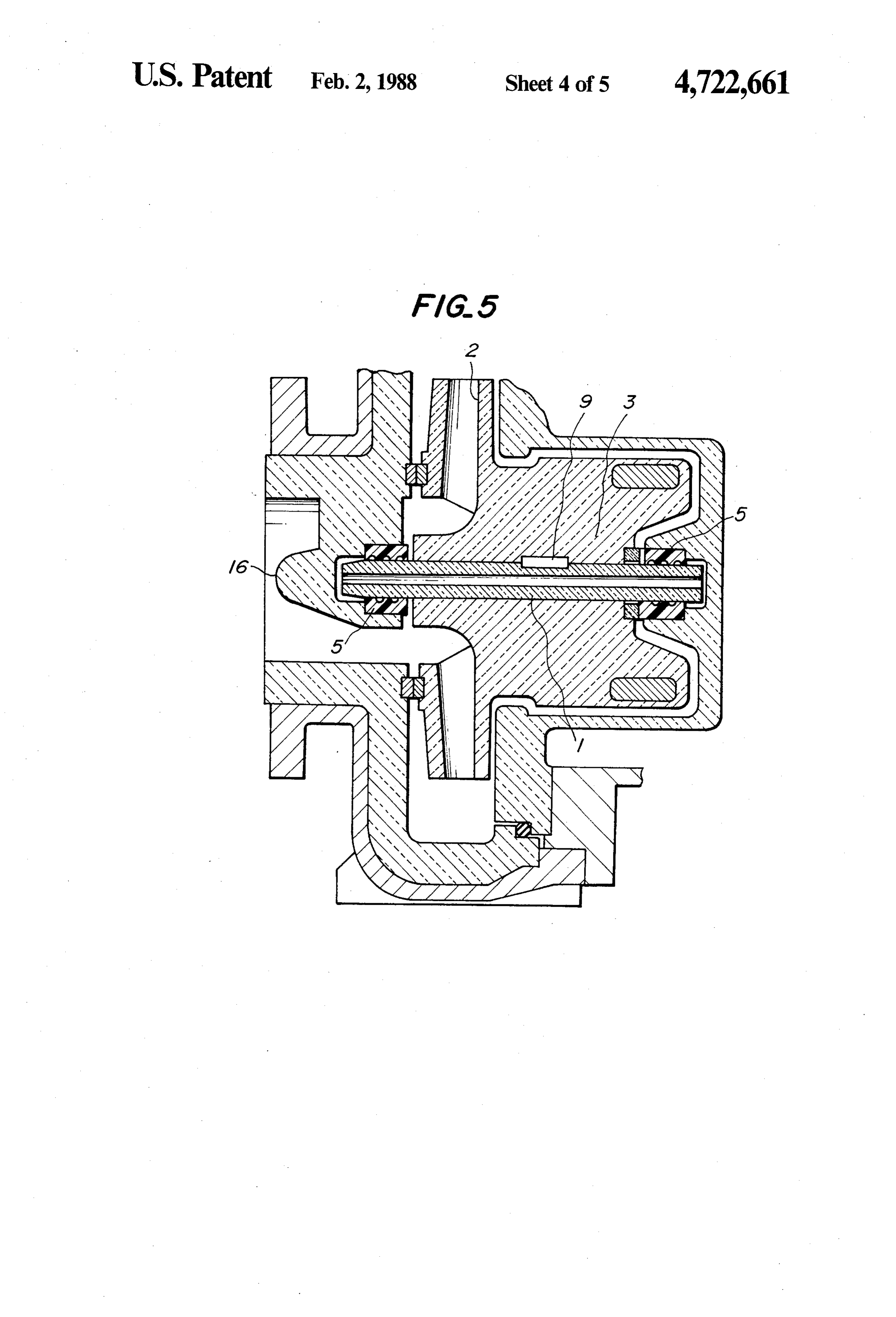
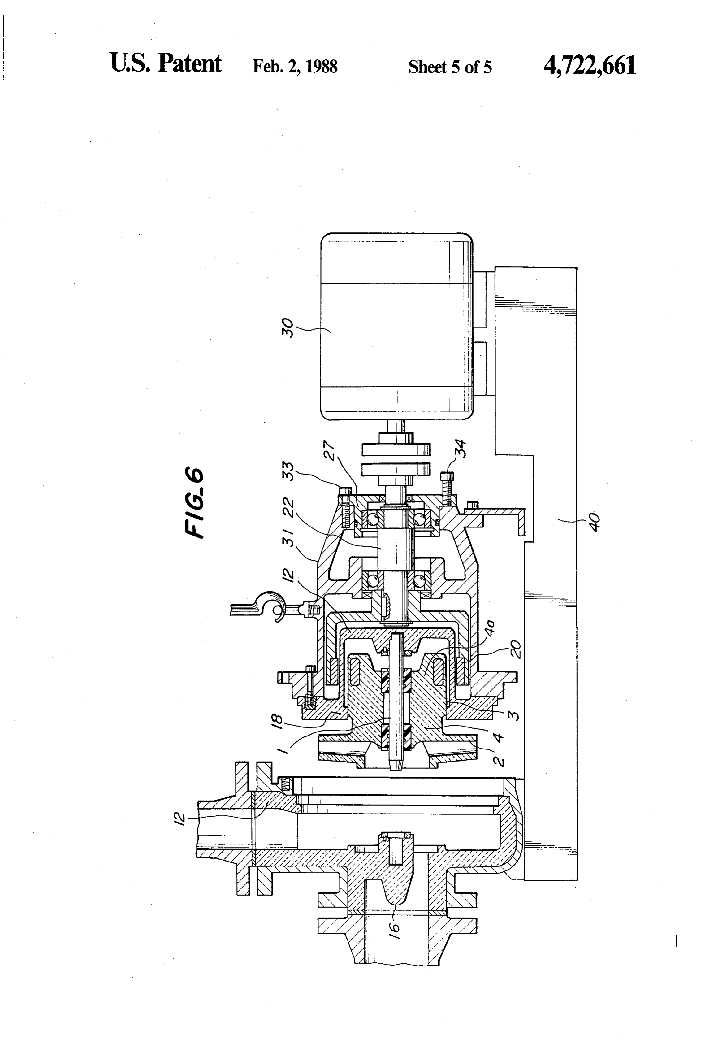
In order to solve this problem, it may be considered BRIEF DESCRIPTION OF THE DRAWINGS to use a large impeller magnet or a large rotor. How FIG. 1 is a sectional view of a magnetic-drive centrif. ever, the large rotor tends to make difficult the assem ugal pump of the prior art;
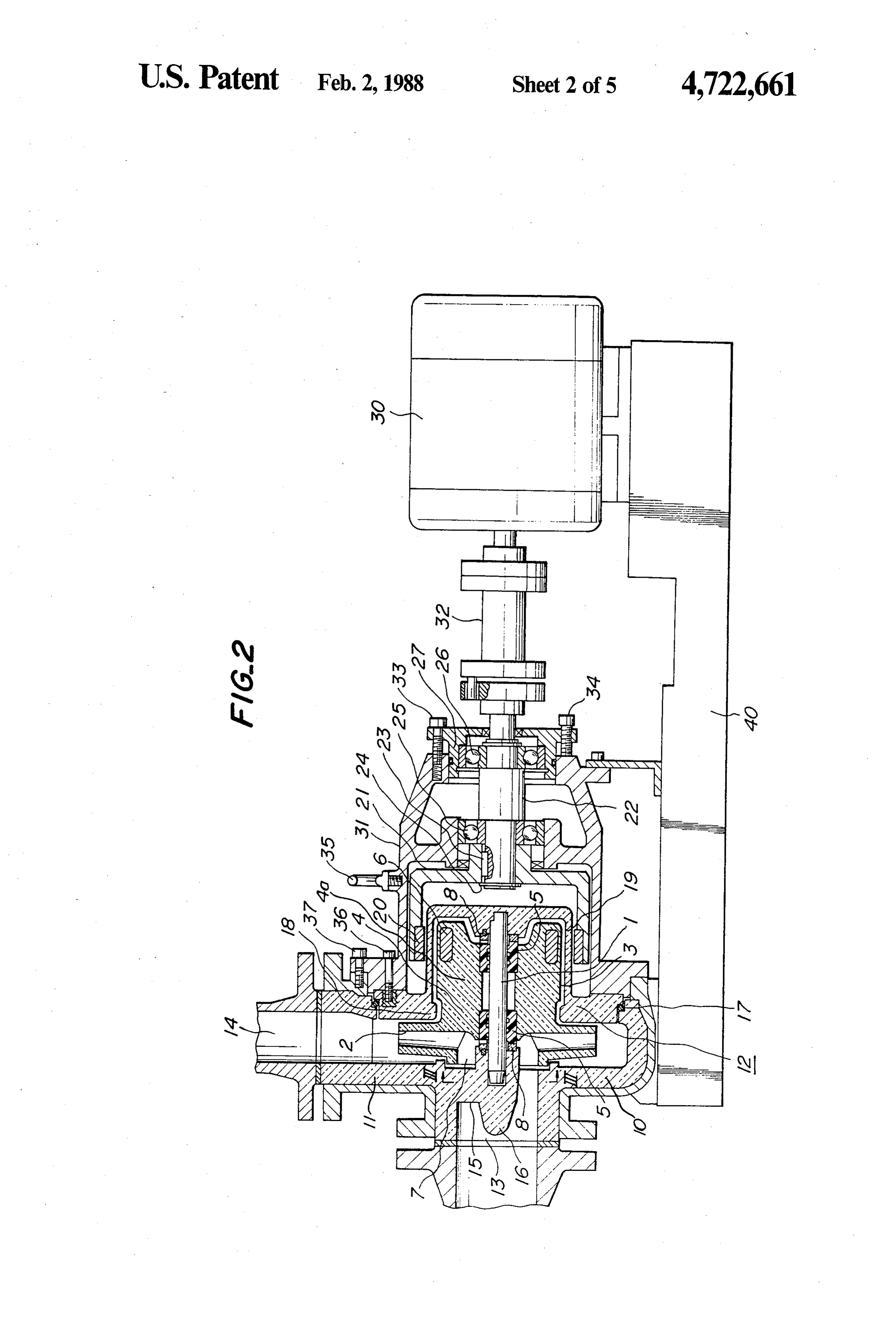
bling and disassembling of the pump in manufacture it FIG. 2 is a sectional view of one embodiment of the or maintenance and inspection. Such a difficulty is magnetic-drive centrifugal pump according to the in caused by the fact that a pump shaft for supporting the vention;
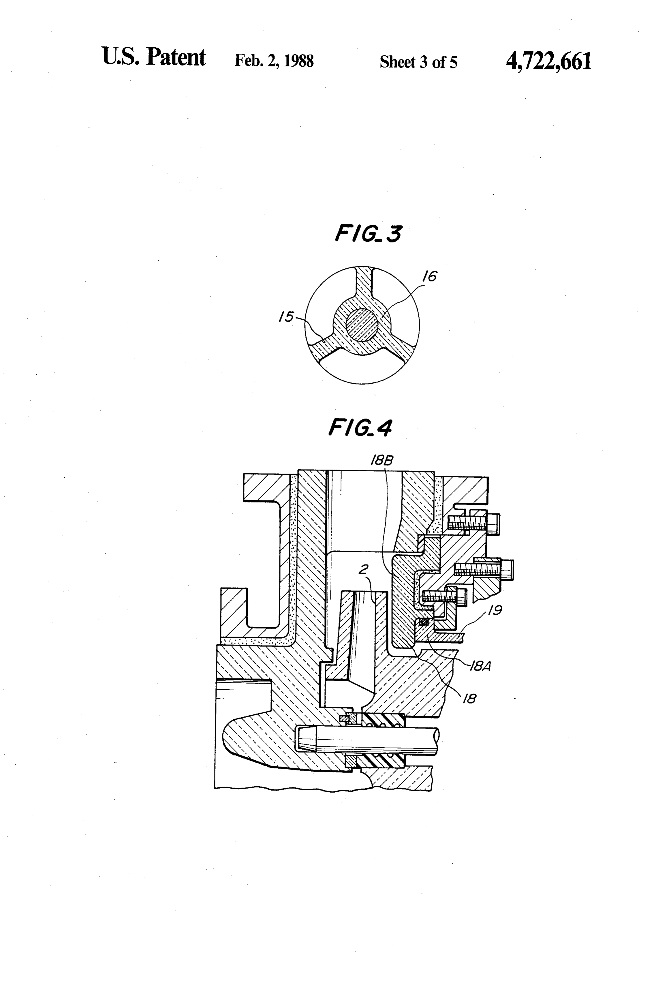
rotor is supported only by a rear wall of a rear casing FIG. 3 is a sectional view taken along a line III-III when the pump is being assembled or disassembled, and in FIG. 2;
the rear wall of the rear casing is subjected to a great 65 FIG. 4 is a sectional view of a main part of a pump of moment. In disassembling of the pump, particularly, a another embodiment of the invention; great moment is caused by a slight deflection of the FIG. 5 is a sectional view of a main part of a pump of pump shaft when its front end is removed from a hub or a further embodiment of the invention; and
Page 8
FIG. 6 is a sectional view of the pump shown in FIG. The boss 16 is supported by ribs 15 provided in an inlet 2 for explaining the disassembling operation of the 13 as shown in FIG. 3.
pump. The front casing 11 forms a pump chamber 7 enclos DESCRIPTION OF THE PREFERRED ing the impeller 2 and further forms an outlet 14 and the EMBODIMENT inlet 13 communicating with the pump chamber 7. The front casing 11 is made of an acid-resistant alumina
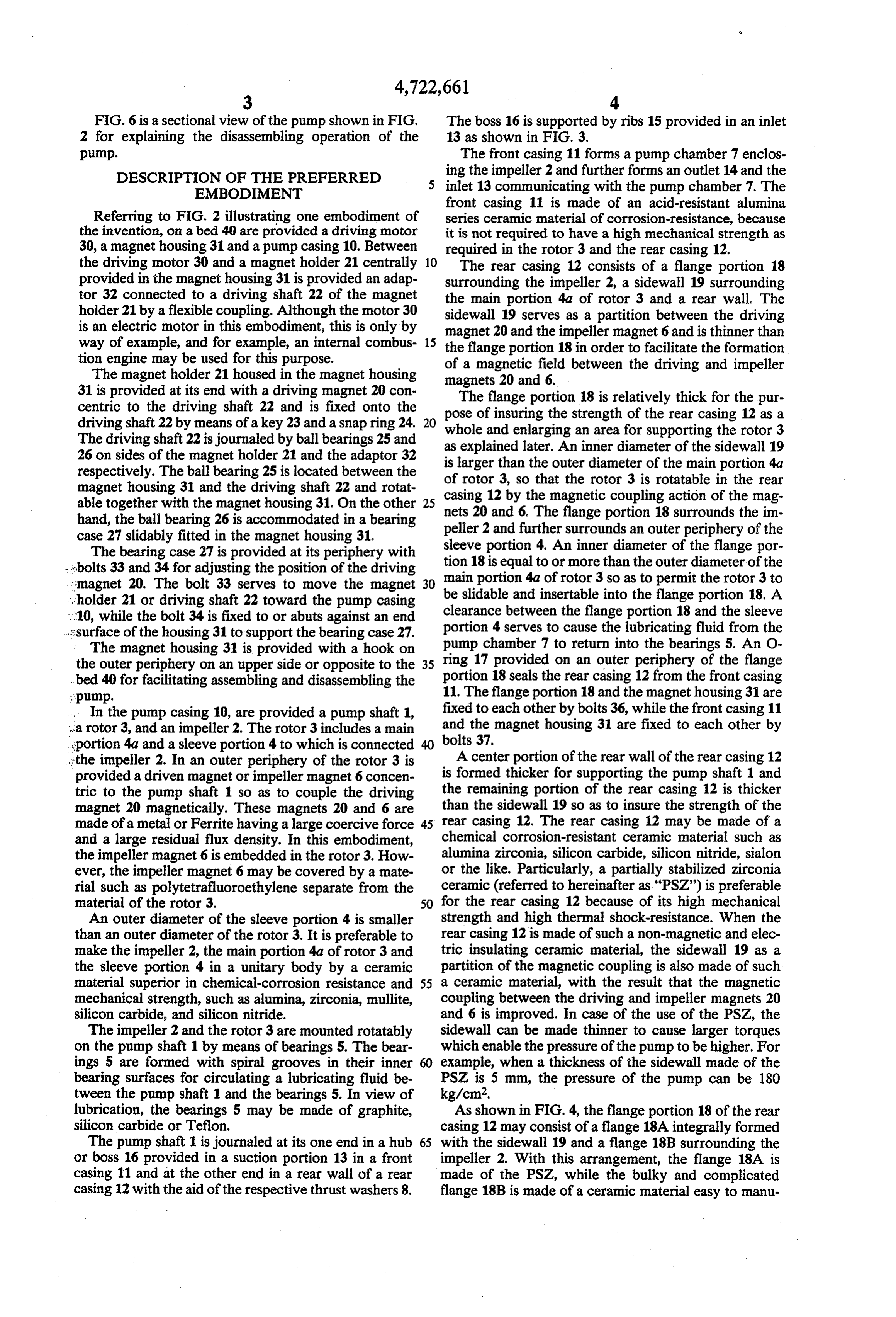
Referring to FIG. 2 illustrating one embodiment of series ceramic material of corrosion-resistance, because the invention, on a bed 40 are provided a driving motor it is not required to have a high mechanical strength as 30, a magnet housing 31 and a pump casing 10. Between required in the rotor 3 and the rear casing 12. the driving motor 30 and a magnet holder 21 centrally 10 The rear casing 12 consists of a flange portion 18 provided in the magnet housing 31 is provided an adap surrounding the impeller 2, a sidewall 19 surrounding tor 32 connected to a driving shaft 22 of the magnet the main portion 4a of rotor 3 and a rear wall. The holder 21 by a flexible coupling. Although the motor 30 sidewall 19 serves as a partition between the driving is an electric motor in this embodiment, this is only by magnet 20 and the impeller magnet 6 and is thinner than way of example, and for example, an internal combus 15 the flange portion 18 in order to facilitate the formation tion engine may be used for this purpose.
The magnet holder 21 housed in the magnet housing of a magnetic field between the driving and impeller magnets 20 and 6.
31 is provided at its end with a driving magnet 20 con The flange portion 18 is relatively thick for the pur centric to the driving shaft 22 and is fixed onto the pose of insuring the strength of the rear casing 12 as a driving shaft 22 by means of a key 23 and a snap ring 24. 20 whole and enlarging an area for supporting the rotor 3 The driving shaft 22 is journaled by ball bearings 25 and as explained later. An inner diameter of the sidewall 19 26 on sides of the magnet holder 21 and the adaptor 32 is larger respectively. The ball bearing 25 is located between the of rotor than the outer diameter of the main portion 4a magnet housing 31 and the driving shaft 22 and rotat casing 123,bysothethatmagneticthe rotor 3 is rotatable in the rear coupling action of the mag able together with the magnet housing 31. On the other nets 20 and 6. The flange portion
18 surrounds the im hand, the ball bearing 26 is accommodated in a bearing peller 2 and further surrounds an outer periphery of the case 27 slidably fitted in the magnet housing 31.
The bearing case 27 is provided at its periphery with sleeve portion 4. An inner diameter of the flange por bolts 33 and 34 for adjusting the position of the driving tion 18 is equal to or more than the outer diameter of the imagnet 20. The bolt 33 serves to move the magnet 30 be main portion 4a of rotor 3 so as to permit the rotor 3 to holder 21 or driving shaft 22 toward the pump casing slidable and insertable into the flange portion 18. A :10, while the bolt 34 is fixed to or abuts against an end clearance portion 4 between the flange portion 18 and the sleeve serves to cause the lubricating fluid from the ...surface of the housing 31 to support the bearing case 27.
The magnet housing 31 is provided with a hook on pump chamber 7 to return into the bearings 5. An O the outer periphery on an upper side or opposite to the 35 ring 17 provided on an outer periphery of the flange bed 40 for facilitating assembling and disassembling the portion 18 seals the rear casing 12 from the front casing pump. 11. The flange portion 18 and the magnet housing 31 are In the pump casing 10, are provided a pump shaft 1, fixed to each other by bolts 36, while the front casing 11 'a rotor 3, and an impeller 2. The rotor 3 includes a main and the magnet housing 31 are fixed to each other by sportion 4a and a sleeve portion 4 to which is connected bolts 37.
...the impeller 2. In an outer periphery of the rotor 3 is A center portion of the rear wall of the rear casing 12 provided a driven magnet or impeller magnet 6 concen is formed thicker for supporting the pump shaft 1 and tric to the pump shaft 1 so as to couple the driving the remaining portion of the rear casing 12 is thicker magnet 20 magnetically. These magnets 20 and 6 are than the sidewall 19 so as to insure the strength of the made of a metal or Ferrite having a large coercive force 45 rear casing 12. The rear casing 12 may be made of a and a large residual flux density. In this embodiment, chemical corrosion-resistant ceramic material such as the impeller magnet 6 is embedded in the rotor 3. How alumina zirconia, silicon carbide, silicon nitride, sialon ever, the impeller magnet 6 may be covered by a mate or the like. Particularly, a partially stabilized zirconia rial such as polytetrafluoroethylene separate from the ceramic (referred to hereinafter as “PSZ") is preferable material of the rotor 3. 50 for the rear casing 12 because of its high mechanical An outer diameter of the sleeve portion 4 is smaller strength and high thermal shock-resistance. When the than an outer diameter of the rotor 3. It is preferable to rear casing 12 is made of such a non-magnetic and elec make the impeller 2, the main portion 4a of rotor 3 and tric insulating ceramic material, the sidewall 19 as a the sleeve portion 4 in a unitary body by a ceramic partition of the magnetic coupling is also made of such material superior in chemical-corrosion resistance and 55 a ceramic material, with the result that the magnetic mechanical strength, such as alumina, zirconia, mullite, coupling between the driving and impeller magnets 20 silicon carbide, and silicon nitride. and 6 is improved. In case of the use of the PSZ, the The impeller 2 and the rotor 3 are mounted rotatably sidewall can be made thinner to cause larger torques on the pump shaft 1 by means of bearings 5. The bear which enable the pressure of the pump to be higher. For ings 5 are formed with spiral grooves in their inner 60 example, when a thickness of the sidewall made of the bearing surfaces for circulating a lubricating fluid be PSZ is 5 mm, the pressure of the pump can be 180 tween the pump shaft 1 and the bearings 5. In view of kg/cm2.
lubrication, the bearings 5 may be made of graphite, As shown in FIG. 4, the flange portion 18 of the rear silicon carbide or Teflon. casing 12 may consist of a flange 18A integrally formed The pump shaft 1 is journaled at its one end in a hub 65 with the sidewall 19 and a flange 18B surrounding the or boss 16 provided in a suction portion 13 in a front impeller 2. With this arrangement, the flange 18A is casing 11 and at the other end in a rear wall of a rear made of the PSZ, while the bulky and complicated casing 12 with the aid of the respective thrust washers 8. flange 18B is made of a ceramic material easy to manu
Page 9
facture, for example, an acid-resistance alumina series the pump is applicable to fluids of large specific gravi ceramic material. ties and high viscosities.
Although the pump casing 10, the impeller 2 and the It is further understood by those skilled in the art that rotor 3 have been explained to be preferably made of the foregoing description is that of preferred embodi ceramic materials in view of the acid-resistance and 5 ments of the disclosed pumps and that various changes mechanical strength, the invention is not limited to such and modifications may be made in the invention without materials and metals or metals with plastic liners may be departing from the spirit and scope thereof. used according to fluids to be treated. What is claimed is:
The impeller 2 and the rotor 3 are rotatable relative to 1. A magnetic-drive centrifugal pump including a the pump shaft 1 in the embodiment shown in FIG.2. 10 driving motor, pump means having a rotor and a mag However, the impeller 2 and the rotor 3 may be fixed to netic coupling consisting of a driving magnet provided the pump shaft 1 which is rotatable relative to the pump on a magnet holder connected to said driving motor and casing 10 as shown in FIG. 5. For this purpose, the an impeller magnet provided in said rotor to be magnet rotor 3 is fixed to the pump shaft 1 by means of a key 9 ically coupled to said driving magnet, wherein said and the pump shaft 1 is journaled by bearings 5 arranged 5 pump means further comprises: in a boss 16 and in a rear wall of a rear casing 12. a pump shaft;
Disassembly of the magnetic-drive centrifugal pump an impeller;
according to the invention for maintenance and inspec a rotor sleeve portion between the impeller and a tion will be explained with reference to FIGS. 2 and 6 main portion of the rotor and having the impeller hereinafter. 20
First, the adaptor 32 is removed from the driving connected thereto, said sleeve portion having an motor 30 and the driving shaft 22. The bolt 34 is then outer diameter smaller than an outer diameter of loosened in a direction in which the bearing case 27 is the main protion of the rotor, said impeller, said removed, while the bolt 33 is tightened to move the main portion of said rotor and said sleeve portion driving shaft 22 toward the rear casing 12. Separate 25 a pump being rotatably mounted on said pump shaft; from the removal of the driving shaft 22, the bolts 37 for casing consisting of a front casing surround fixing the magnet housing 31 to the pump casing 10 are ing said impeller and a rear casing surrounding a removed to bring the magnet housing 31 into a movable rear surface of the impeller and said sleeve portion condition. Then, the magnet housing 31 is moved and main portion of said rotor; toward the driving motor 30 so as to move the pump 30 said rear casing having at a location opposite said shaft 1 from the boss 16 to an extent that the pump shaft sleeve portion a first inner diameter which is large 1 is still supported in the boss 16. enough to enable an outer circumference of said The movement of the driving shaft 22 results in a main portion of said rotor to slide therein, and at a movement of the driving magnet 20, so that the rotor 3 location opposite said main portion of said rotor a provided with the impeller magnet 6 magnetically cou 35 second inner diameter larger than said first inner pled with the driving magnet 20 is slid on the pump diameter; and shaft 1 toward the front casing 11 so as to cause the one end of said pump shaft being journaled in a boss outer circumference of the main portion 4a of rotor 3 to having ribs provided in an inlet of said front casing, be opposite the flange portion 18 of the rear casing 12. and the other end of said pump shaft being jour Then, the magnet housing 31 including the rotor 3 is naled in a rear wall of said rear casing; moved toward the driving motor 30 to remove the whereby the rotor is adequately supported by the pump shaft 1 from the boss 16 of the front casing 11. rear casing during disassembly so as to avoid appli By the above successive operations, the front casing cation of off-set stresses to the pump shaft and inner 11 is removed from the rotor 3 and the rear casing 12. In surfaces of the rear casing. this removing operation, the rotor 3 is supported by the 45 2. A magnetic-drive centrifugal pump as set forth in flange portion 18, so that the rotor 3 does not apply any claim 1, wherein said magnet holder comprises position off-set stress to the pump shaft 1 and inner surfaces of adjusting means for moving said magnet holder and said the rear casing 12. magnetically coupled rotor toward said front casing In order to separate the rotor 3 from the rear casing during disassembly.
12, the rotor 3 is slid on the inner circumferential sur 50 3. A magnetic-drive centrifugal pump as set forth in face of the flange portion 18 of the rear casing 12 to claim 2, wherein said position adjusting means com remove the rotor 3 out of the rear casing 12 together prises a bearing case mounted through a bearing on a with the impeller 2. driving shaft of said magnet holder, and a position ad After the magnetic-drive centrifugal pump has been justing bolt provided between said bearing case and the disassembled in this manner, respective parts are 55 magnet housing accommodating said magnet holder. cleaned for maintenance and inspected concerning for 4. A magnetic-drive centrifugal pump as set forth in example wearing of the bearings and damaged condi claim 1, wherein said rear casing is made of a ceramic tions of the impeller. material.
An assembling operation of the pump will not be 5. A magnetic-drive centrifugal pump as set forth in described since the assembling can be effected in re 60 claim 4, wherein said ceramic material is zirconia ce verse steps to those of the disassembling above de ramic, scribed. 6. A magnetic-drive centrifugal pump as set forth in As can be seen from the above description, the mag claim 4, wherein a thickness of said rear casing between netic-drive centrifugal pump is easy to assemble and the driving and impeller magnets is thinner than a thick disassemble and can employ a large pump rotor to im ness of that portion of said rear casing which surrounds prove the performance of this pump without any trou said rear surface of the impeller and said sleeve. ble even if the weight of the rotor is increased, so that k
Provenance
- Collection
- Cited prior art
- Original PDF
- patentimages.storage.googleapis.com →
- Filed
- 1985-10-09
- Pages
- 9
- Method
- pdftotext (the PDF's own text layer) + pdftoppm 300dpi page scans
- Source
- Google Patents bibliographic record
- Granted
- 1988-02-02
- Inventors
- Motoshige Mizuno; NGK Insulators Ltd
- Transcribed from
- patentimages.storage.googleapis.com →