patent · US3868929
Lubricating oil supply system for rotary engine
4 March 1975
Page 1 — bibliographic record
United States Patent (19) [11] 3,868,929 Ishikawa (45) Mar. 4, 1975 54). LUBRICATING OIL SUPPLY SYSTEM FOR 3, 140,700 7/1964 Nollinger.................... 1231196 RX ROTARY ENGINE 3,738,453 6/1973 Boswell.............................. 184/6.6
75) Inventor: Yoshikazu Ishikawa, Tokyo, Japan 73) Assignee: Nissan Motor Company, Limited, FOREIGN PATENTS OR APPLICATIONS Yokohama City, Japan 1451,730 3, 1970 Germany ........................... 123/8.0
21 Appl. No.: 346,763 Primary Examiner-Manuel A. Antonakas
30 Foreign Application Priority Data 57 ABSTRACT Apr. 3, 1972 Japan................................ 47-33327
A lubricating oil supply system for a rotary internal 52 U.S. Cl............ 123/8.09, 123/8. 13, 1231196 R, combustion engine and adapted to supply a lubricating 41 8/100, 123/73 AD oil onto the inner surface of the engine housing. The 5) Int. Cl. ............................................ FOc 21/04 lubricating oil supply system has a diffuser disposed in 58) Field of Search....... 184/6.16; 1231196 R, 8.01, the wall of a mixture supply pipe the diffuser serving 23/8.09, 8.13, 41 8/83, 90, 100 to diffuse the lubricating oil into uniformly fine drop lets which are mixed with air or the mixture of air and (56 References Cited fuel supplied into the engine.
UNITED STATES PATENTS
2,313,387 3/1943 McArthur et al................... 418/100 1 Claim, 1 Drawing Figure
Page 2
Drawing sheet — no readable text.
Page 3
LUBRICATING OL SUPPLY SYSTEM FOR Another object of the present invention is to provide ROTARY ENGINE a lubricating oil supply system which is simple in con struction and economical to manufacture.
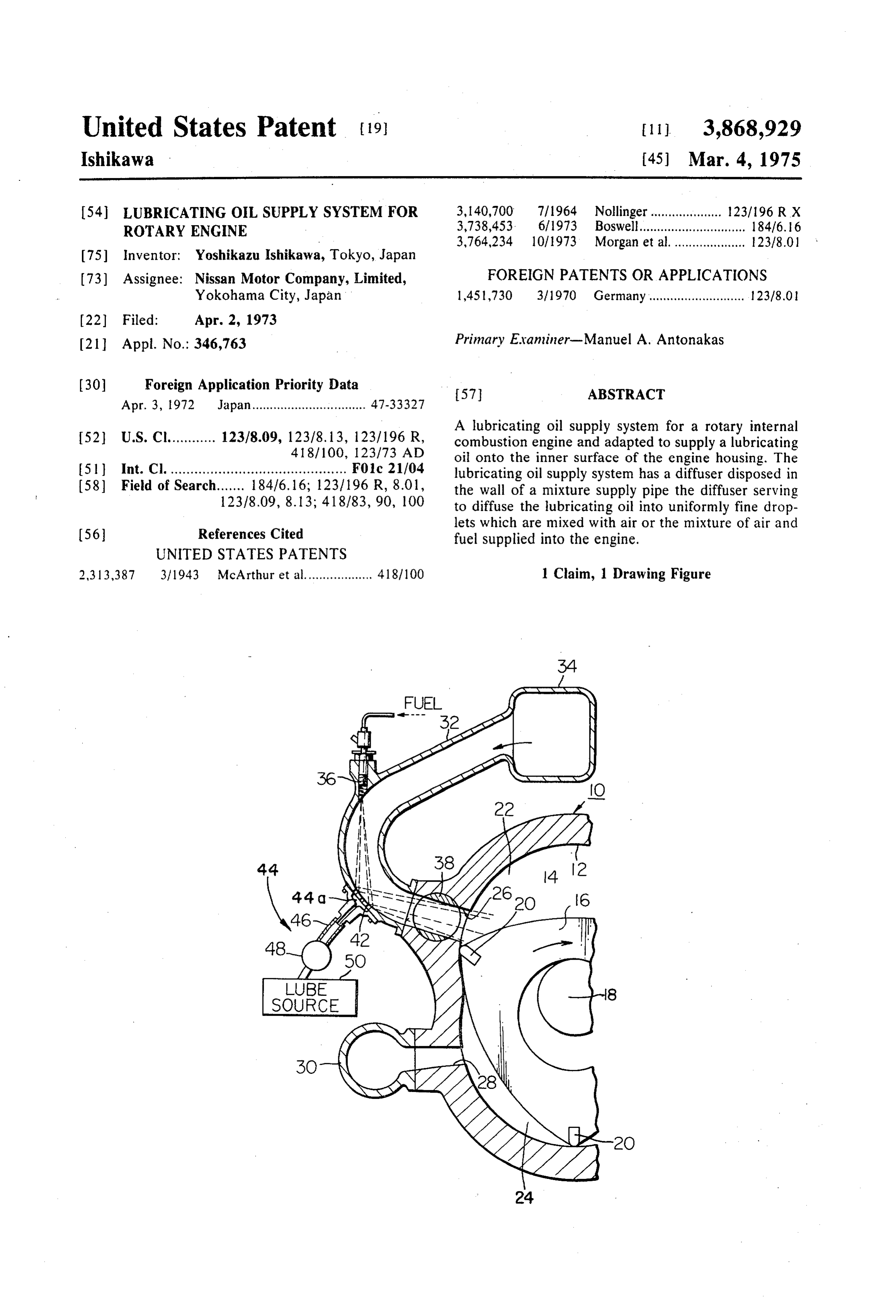
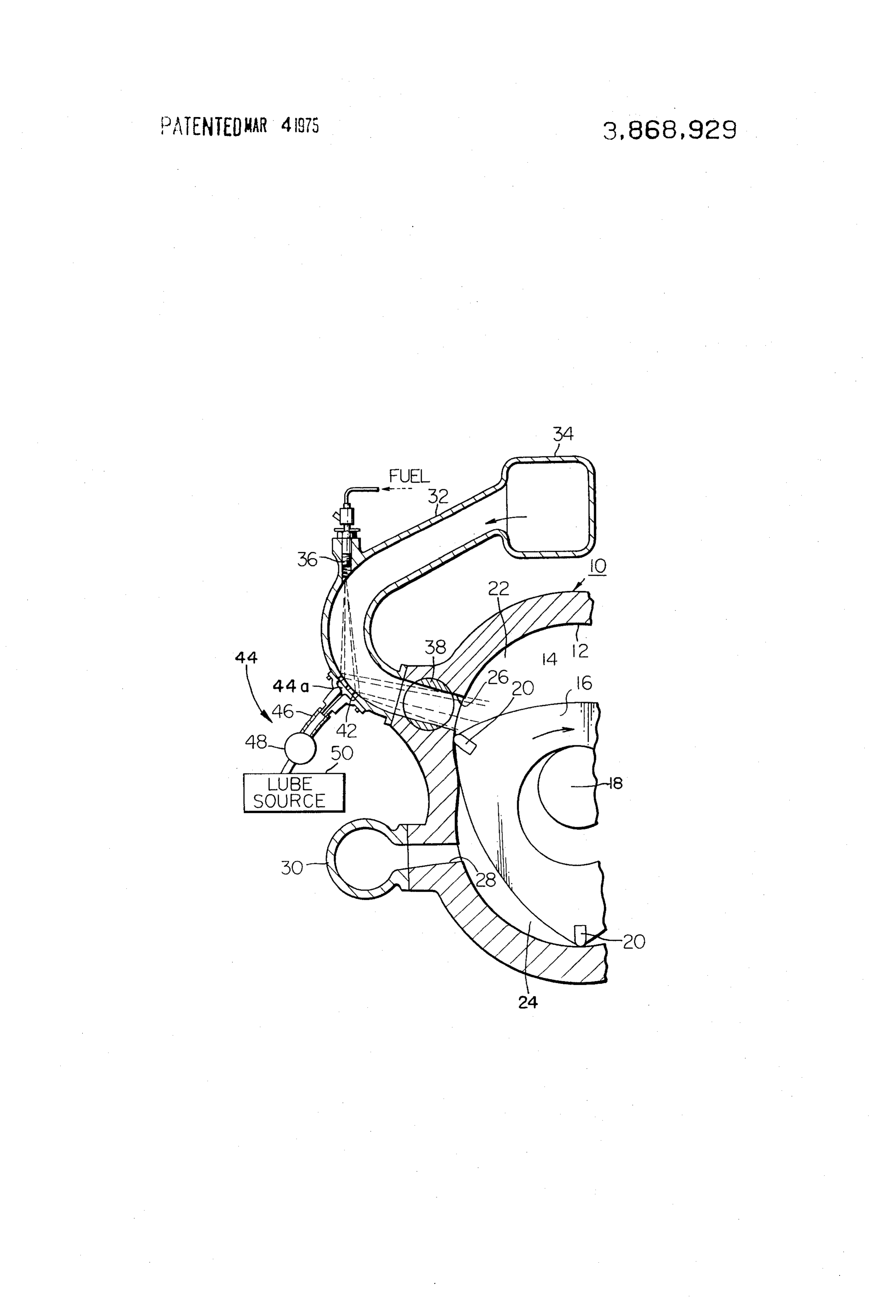
This invention relates in general to rotary internal Still another object of the present invention is to pro combustion engines and, more particularly, to a lubri 5 vide a lubricating oil suply system which can be readily cating oil supply system for such engines. installed in existing rotary internal combustion engines As is well known, a rotary internal combustion en without causing substantial modifications or changes in gine is usually comprised of a housing having a cavity the component parts of the engine. therein and a rotor disposed therein rotatable relative According to the present invention, there is provided to the housing, about an axis laterally spaced from but 10 a lubricating oil supply system which is specifically parallel to the axis of the cavity. The rotor is journalled suited for use in a rotary internal combustion engine of on the eccentric portion of a shaft which is co-axial the trochoidal type. The rotary internal combustion en with the housing and which in turn is journalled in bear gine to which the lubricating oil supply system of the ings carried by the housing end walls. The housing has present invention is applied commonly includes a hous axially spaced end walls and a peripheral wall intercon 15 ing having a cavity defined by an epitrochoidal inner necting the end walls to form the cavity, the inner sur surface of the housing peripheral wall and axilly spaced face of the cavity peripheral wall having a multi-lobed end walls, and a rotor rotatably disposed in the cavity profile which preferably is basically an epitrochoid. of the housing. The housing has intake and exhaust The rotor has a peripheral surface with a plurality of ports formed in the peripheral wall of the engine hous circumferentially spaced apex portions, each carrying 20 ing, the intake port being connected to a mixture sup a radially movable seal for sealing engagement with the ply pipe which in turn is connected to an air inlet. The epitrochoidal inner surface of the housing peripheral amount of air-fuel mixture supplied into the engine is wall to form a plurality of working chambers which controlled by a throttle valve operatively disposed in vary in volume upon relative rotations of the housing 25 the intake port of the engine housing. In a preferred and the rotor. In this construction, it has been a com embodiment of the present invention, a lubricating oil mon practice to luricate the inner surfaces of the cavity supply nozzle is mounted on the mixture pipe upstream for reducing friction between the surfaces of the hous of the throttle valve and arranged to open to the mix ing and the rotor. There are two different kinds of ture pipe through a diffusing means or a porous mem methods proposed in the prior art for supplying the lu ber. The diffusing means serves to diffuse the lubricat bricating oil into the cavity of the engine housing. One 30 ing oil into fine droplets which are mixed with the mix of these methods is to have the lubricating oil mixed ture of fuel and air flowing through the mixture pipe with liquid fuel, the mixture of which in turn is mixed during normal operating conditions of the engine. Dur with air to provide a combustible mixture which is sup ing decelerating conditions of the engine, the lubricat plied into the cavity of the engine housing. The lubri ing oil admitted through the diffusing means is mixed cating oil contained in the combustible mixture thus 35 with air supplied from the air inlet and delivered to the supplied into the cavity of the engine housing is then cavity of the engine housing. Thus, the lubricating oil applied onto the inner surfaces of the housing. A diffi is uniformly distributed in the air or in the mixture of culty is encountered in this prior art in that, when the air and fuel so that, when the suction chamber in the engine is operating under decelerating conditions, very 40 cavity of the engine housing is compressed by the rotor, little fuel is supplied into the engine and, therefore, lu the lubricating oil is satisfactorily applied to the epitro bricating oil is not supplied sufficiently into the engine choidal inner surface of the housing peripheral wall. resulting in excessive wear of the apex seals of the ro These and other features and advantages of the pres tor. ent invention will become more apparent from the fol Another expedient proposed in the prior art is to di lowing description when taken in conjunction with a rectly supply the lubricating oil into the cavity of the 45 single FIGURE of the drawing, which illustrates a pre engine housing through, for example, a lubricating oil ferred embodiment of the lubricating oil supply system injection nozzle formed in slit-shape at the peripheral according to the present invention. edge of the intake port of the housing. This practice is Referring to the single FIGURE of the drawing, there advantageous in that, even when the engine is operat 50 is shown a rotary internal combustion engine incorpo ing under the decelerating condition, the lubricating oil rating the lubricating oil supply system implementing is supplied into the cavity of the engine housing for sat the present invention. The rotary internal combustion isfactory lubrication. However, a difficulty is still en engine is shown to include a housing 10 having a pe countered in this prior practice in that it is difficult to ripheral wall formed with an epitrochoidal inner sur inject the lubricating oil in such a manner as to apply face 12 defining a cavity 14 with axially spaced end the lubricating oil uniformly on the inner surfaces of 55 walls (not shown) interconnected by the housing pe the working chambers in the housing. ripheral wall, and a rotor 16 rotatably disposed in the It is, therefore, an object of the present invention to cavity 14 of the housing. The rotor 16 is journalled on provide a new and improved lubricating oil supply sys an eccentric portion of a shaft 18, which is co-axial tem for a rotary internal combustion engine of the tro 60 with the housing and which in turn is journalled in bear choidal type. ings carried by the housing end walls, although not shown. This rotor 16 has a peripheral surface with a
Another object of the present invention is to provide plurality a lubricating oil supply system which is capable of ap of circumferentially spaced apex portions, plying lubricating oil to an inner surface of a housing each carrying a radially movable seal 20 which seal ingly engages the epitrochoidal inner surface 12 of the peripheral wall of a rotary internal combustion engine 65 housing in a unform manner throughout various operating con 10 to form a plurality of working chambers dition of the engine whereby improved engine perform which vary in volume upon rotation of the rotor 16 rel ance efficiency is obtained. ative to the housing 10. In the illustrated embodiment,
Page 4
the working chambers 22 and 24 are shown as suction is passed toward the diffuser 42 as shown by the dotted. and exhaust chambers, respectively. The housing 10 lines in the drawing, the fine droplets of the lubricating has peripheral intake and exhaust ports 26 and 28, oil are mixed with and carried by the mixture of fuel which open to the suction chamber 22 and exhaust and air introduced into the suction chamber 22 of the chamber 24, respectively. The exhaust port 28 is con engine. The mixture of the lubricating oil and the air nected to an exhaust pipe 30 vented to the atmosphere fuel mixture is compressed in the suction chamber 22 to discharge exhaust gases from the exhaust chamber when it becomes the compression chamber by the ac 24 to the atmosphere. The intake port 26 communi tion of the rotor 16 and, consequently, the lubricating cates with a mixture pipe 32, which in turn communi oil is applied uniformly on the epitrochoidal inner sur cates with an air inlet 34 through which air is intro O face of the housing peripheral wall, duced into the mixture pipe 32. A fuel injection nozzle During decelerating condition of the engine, the fuel 36 is shown as being mounted on the mixture pipe 32 supply is shut off while only air is supplied into the suc for injecting liquid fuel thereinto which is mixed with tion chamber of the engine so that the lubricating oil in air supplied from the air inlet 34 to provide an air-fuel the form of fine droplets is mixed with air and carried mixture. It should be noted that while, in the illustrated 15 thereby.
embodiment, the rotary engine is shown as at the type It will now be appreciated from the foregoing de having a fuel injection nozzle, the rotary engine may be scription that the lubricating oil supply system carrying of the carburetor type. The air-fuel mixture thus pro out the present invention is capable of uniformly dis vided is then supplied through the intake port 26 into tributing the lubricating oil to the inner surface of the the suction chamber 22 formed in the cavity 14. A 20 peripheral wall of the engine housing.
throttle valve 38 is operatively disposed in the intake It will also be noted that the lubricating oil supply sys port 26 and rotatable therein to vary the flow of air-fuel tem of the present invention is capable of supplying the mixture supplied to the suction chamber 22. lubricating oil into the engine even when the engine is According to an important feature of the present in operating under decelerating condition.
vention, the lubricating oil is intended to be mixed with 25 It will further be understood that the lubricating oil air or the mixture of air and fuel to be introduced into supply system according to the present invention is sup the suction chamber of the engine. To achieve this fea plied into the engine in desired amounts at all times ture, the lubricating oil supply system, which is gener throughout various operating conditions of the engine ally designated by the reference numeral 40, comprises since the system of the present invention is not affected a diffuser or porous member 42, which is shown as 30 by the suction created in the suction chamber of the en being received or mounted on the wall of the mixture gine especially when the engine is maintained in a de supply pipe 32 in the path of fuel spray from the fuel celerating condition.
injection nozzle 36 for diffusing the lubricating oil into What is claimed is:
uniformly fine droplets. The lubricating oil is supplied 1. In combination with a rotary internal combustion into the pipe 32 through the diffuser 42 by means of a 35 engine of the fuel injection type having an intake port, lubricating oil supply unit 44 which is mounted on the a mixture supply pipe connected to an air inlet and outer wall of the mixture supply pipe 32 by some suit communicating with said intake port, a fuel injection able fastener means such as bolts and nuts. As shown, nozzle mounted in said mixture supply pipe down the lubricating oil supply unit 44 has formed therein a stream of said air inlet and adapted for injecting fuel lubricating oil distributing chamber 44a into which a 40 toward a limited part of a wall of said mixture supply lubricating oil supply pipe 46 opens. The lubricating oil pipe downstream of said fuel injection nozzle, a lubri distributing chamber 44a serves to evenly distribute the cating oil supply system comprising a source of lubri lubricating oil entering the diffuser 42 so that the lubri cating oil, a metering pump communicating with said cating oil can be diffused into air or the mixture of air source of lubricating oil, a lubricating oil supply pipe and fuel in a satisfactory manner. The lubricating oil 45 communicating with said source of lubricating oil supply pipe 46 is connected through a metering pump through said metering pump, a lubricating oil supply 48 to a source of lubricating oil 50. It is to be under unit mounted on an outer wall of said mixture supply stood that the metering pump 48 may be driven in rela pipe and having a lubricating oil distributing chamber tion with the engine speed whereby the metering pump communicating with said lubricating oil supply pipe 48 is synchronized with the engine speed to deliver the 50 and opening into said mixture supply pipe at the limited lubricating oil into the engine in desired amounts. part thereof, and a diffuser mounted in the wall of said With the construction mentioned hereinabove, dur mixture supply pipe at the limited part thereof in the ing normal operating condition of the engine, the lubri path of fuel spray from said fuel injection nozzle, said cating oil is supplied through the pipe 46 into the lubri lubricating oil distributing chamber of said unit distrib cating oil distributing chamber 44a of the lubricating 55 uting lubricating oil into said mixture supply pipe supply unit 44 by the action of the metering pump 48. through said diffuser, whereby the lubricating oil is uni The lubricating oil in the chamber 44a is then forced formly diffused into fine droplets which are mixed with through and diffused by the diffuser 42 into fine drop the mixture of air and
fuel
tosk beck supplied
to the engine.
lets. Since, in this condition, the mixture of fuel and air
Provenance
- Collection
- Cited prior art
- Original PDF
- patentimages.storage.googleapis.com →
- Filed
- 1973-04-02
- Pages
- 4
- Method
- pdftotext (the PDF's own text layer) + pdftoppm 300dpi page scans
- Source
- Google Patents bibliographic record
- Granted
- 1975-03-04
- Inventors
- Yoshikazu Ishikawa; Nissan Motor Co Ltd
- Transcribed from
- patentimages.storage.googleapis.com →