patent · US4676068
System for solar energy collection and recovery
30 June 1987
Page 1 — bibliographic record
United States Patent (19) 11) Patent Number: 4,676,068. Funk (45) Date of Patent: Jun. 30, 1987 54 SYSTEM FOR SOLAR ENERGY 4,280,327 7/1981 Mackay........................... 26/451 X COLLECTION AND RECOVERY 4,280,482 7/1981 Nilsson, Sr. ......................... 126/430
76) Inventor: Harald F. Funk, 68 Elm St., Murray 4,318,393 3/1982 Goldstein ........................ 126/45 X Hill, N.J. 07974 Primary Examiner-Allen M. Ostrager (21) Appl. No.: 812,989 Attorney, Agent, or Firm-Sixbey, Friedman & Leedom 22 Filed: Dec. 24, 1985 57 ABSTRACT Related U.S. Application Data A system for the collection of solar radiation and the recovery of thermal energy therefrom includes solar 63 Continuation-in-part of Ser. No. 574,628, Jan. 27, 1984, radiation receiver means at or near the focus of a solar abandoned, which is a continuation-in-part of Ser. No. radiation concentrating means for absorbing the solar 530,650, Sep. 9, 1983, Pat. No. 4,513,573, which is a radiation, converting it to thermal energy and transfer
No. 4,411,346, which is a continuation-in-part of Ser. ring the thermal energy to ambient air drawn over the No. 962,103, Nov. 17, 1978, Pat. No. 4,265,088, which receiver means and, thereafter, directed to an energy is a continuation-in-part of Ser. No. 674,219, Apr. 6, reclamation unit. In the energy reclamation unit the 1976, Pat. No. 4,126,000, which is a continuation-in heated ambient air deposits a portion of its thermal part of Ser. No. 565,045, Apr. 4, 1975, Pat. No. energy in regenerators, from which it is recovered by a 3,970,524, which is a continuation-in-part of Ser. No. compressed air stream, and transfers a portion of its 486,562, Jul. 8, 1974, abandoned, which is a continua thermal energy to a power fluid. The thermal energy of tion-in-part of Ser. No. 252,610, May 12, 1972, aban the ambient air is reclaimed from the compressed air doned.
stream and the power fluid as shaft work in expansion 51 Int. Cl." ...... ... FO3G 7/02; F24J 3/02 turbines. In a preferred embodiment, the solar radiation 52 U.S. C. .............................. 60/641.14; 60/641.15; receiver means comprises a high temperature resistant, 126/430; 126/438; 126/451 porous, convex enclosure having inner and outer po 58) Field of Search ....................... 126/430,438, 451; rous, convex surfaces arranged in spaced apart nested 60/650, 682, 64.14, 641.15 relationship for defining therebetween an annular space 56) References Cited which is randomly filled with a plurality of close to
ideal black body solar radiation absorbing elements.
4,262,484 4/1981 Jubb et al. ...................... 26/438 X 21 Claims, 5 Drawing Figures
Page 2
Drawing sheet — no readable text.
Page 3
Drawing sheet — no readable text.
Page 4
Drawing sheet — no readable text.
Page 5
ergy to a heat transfer fluid, is U.S. Pat. No.
SYSTEM FOR SOLAR ENERGY COLLECTION 4,081,966-deCeus which discloses a solar operated AND RECOVERY power generator wherein concentrated solar energy is focused onto copper tubes having a low boiling fluid
CROSS REFERENCE TO RELATED therein for vaporizing and superheating the fluid and APPLICATIONS then expanding the fluid in turbine means. U.S. Pat. No. The present application is a continuation-in-part of 4,235,225-Doebel discloses a device for improving application Ser. No. 574,628, filed Jan. 27, 1984, now solar energy collection efficiency wherein the sun's abandoned, which application was a continuation-in 10 solar energy rays are concentrated onto a plurality of part of application Ser. No. 530,650, filed Sept. 9, 1983 metal, e.g., copper, brass, aluminum, steel, cores (now U.S. Pat. No. 4,513,573), which application was a through which a heat transfer medium is circulated. continuation of application Ser. No. 205,348, filed Nov. Likewise, U.S. Pat. No. 4,153,039-Carroll shows the 10, 1980 (now U.S. Pat. No. 4,411,346), which applica use of parabolic mirrors for focusing sunlight onto a tion was a continuation-in-part of application Ser. No. 15 metallic pipe designed for carrying a heat transfer fluid 962,103, filed Nov. 17, 1978 (now U.S. Pat. No. therein. U.S. Pat. No. 4,068,474-Dimitroff discloses 4,265,088), which application was a continuation-in-part that steam to be supplied to a turbine may be generated of application Ser. No. 674,219, filed Apr. 6, 1976 (now by concentrating solar energy onto a conductor element U.S. Pat. No. 4,126,000), which application was a con having portions extending into a water reservoir for tinuation-in-part of application Ser. No. 565,045, filed transferring the solar energy via conduction through Apr. 4, 1975 (now U.S. Pat. No. 3,970,524), which ap 20 the conductor element to the water for producing plication was a continuation-in-part of application Ser. Steann.
No. 486,562, filed July 8, 1974 (now abandoned), which The use of indirect heat transfer, such as is disclosed application, in turn, was a continuation-in-part of appli in the aforedescribed solar collection systems is ineffi cation Ser. No. 252,610, filed May 12, 1972 (now aban cient and results in a substantial loss of thermal energy. doned), the disclosures of which are incorporated 25 In addition, the very high temperatures at the focus are herein by reference. sufficient to melt highly conductive, high heat transfer DESCRIPTION coefficient metals, such as copper or aluminum, and 1. Technical Field therefore these metals cannot be used. As a result, high temperature
The present invention relates generally to a system coefficient metals 30 solar collectors utilize low heat transfer such as stainless steel for the tubes or for the efficient utilization of solar energy and, more pipes. Such metals can withstand the high temperatures particularly, to methods and apparatus for the collec tion of solar radiation and the recovery of thermal and at the focus but their relatively poor heat transfer char acteristics, both in absorbing the sun's rays and in con conversion to mechanical energy therefrom. ducting the thermal energy to the heat transfer fluid,
Many systems of various types have been devised for the introduce significant additional thermal inefficiencies to the collection and recovery of thermal and conversion heat transfer process. An additional problem with to mechanical energy from solar radiation. In some conventional solar collection systems is that the metal systems, simple unfocused solar collectors are used to tubes and pipes are continually subjected to thermal collect solar radiation and convert it to mechanical stresses which weaken the metals. These thermal energy. These systems typically operate in a relatively stresses are created by the uneven heating resulting low temperature range, for example from 80°-125 F. from the parabolic mirror sides of the tubes and pipes Other systems operate at much higher temperatures, up being very hot compared to the sun facing sides and by to several thousand degrees, and utilize concentrating the constant thermal cycling due to daytime heating and means to focus the solar radiation in an effort to more 45 nighttime cooling of the tubes and pipes. efficiently collect and recover the energy thereof. As a result of the foregoing problems the use of metal The higher temperature systems frequently employ heat exchange tubes and pipes in focused solar radiation parabolic mirrors, reflectors or other solar radiation collectors is clearly not desirable. Nevertheless, metal focusing devices, to concentrate the radiation in a small tubes and pipes appear to be better than non-metal alter area, typically referred to as the focus of the mirror or 50 natives available to date. For example, the non-metal device. At the focus, where temperatures of heat exchange elements for solar heating disclosed in 1000-1200° C. are not uncommon, the solar radiation U.S. Pat. Nos. 4,257,481-Dobson and impinges on and transfers its thermal energy via a heat 4,222,373-Davis include a dark colored upper layer exchanger to a heat exchanger fluid from which the onto which the solar radiation impinges and internal thermal energy is reclaimed in any number of well 55 ducting, provided by embedded pipes or formed in the known ways. The heat exchanger generally comprises non-metal element, in which a fluid transfer medium, an array of tubes or pipes carrying a heat transfer fluid, such as water, circulates. Presumably, the exposed, dark such as a power fluid, air or steam. Thermal energy upper layer surfaces absorbs the sun's rays and transfers reaches the fluid via indirect heat transfer, the thermal the thermal energy through the body of the non-metal energy of the solar radiation impinging on the tube or 60 element to the fluid circulating in the ducting. How pipes and the surrounding air to transfer heat to the ever, such an element is thermally inefficient in its abil tubes and pipes by radiation and convection and then ity to transfer heat because the fluid is in closed conduits through the walls of the tubes or pipes to the heat trans not exposed to the solar radiation and heat transfer fer fluid by conduction and convection. thereto relies primarily upon conduction through the Illustrative of the patent art relating to focused solar 65 non-metal element, an element formed of concrete, radiation systems for the collection, recovery and recla cement or ceramic materials which are even poorer mation of solar energy, which systems utilize conduc thermal conductors than metal such as stainless steel. tion through metallic members to transfer thermal en The same is true in U.S. Pat. No. 2,760,920 wherein a
Page 6
parabolic reflector focuses the sun's rays onto the para In one aspect of the present invention this is accom bolic, substantially black body heat absorbing surface of plished by providing a system for the collection of solar a steam generating furnace. Water from any suitable radiation and the recovery of thermal energy therefrom source is fed through the furnace and is heated to pro which includes solar radiation receiver means at or near duce steam by thermal energy conducted through the the focus of a solar radiation concentrating means for black body. directly transferring the solar energy to the receiver There have been some efforts at solving these heat means and from the receiver means to the ambient air, transfer problems by employing ambient air drawn, via a the receiver means having a configuration and being fan or like compressor means, through a solar energy formed of materials which maximize absorption of solar receiver and over solar energy collection elements 10 radiation and thermal transfer to the ambient air. which have been heated, at least to a substantial extent, In another aspect of the present invention the ambient by radiation. For example, U.S. Pat. No. 4,394,859 air which is heated by thermal energy transfer from the Drost teaches a tower-mounted solar energy receiver receiver means is drawn into an energy reclamation unit for heating air adjacent the receiver and drawn, via a 15 wherein the heated ambient air is cooled in regenerators fan, through air passages defined by a vertically ori in heat-exchange relationship with solid materials hav ented elongated slat array, over fin-shaped individual ing relatively large surface area to volume ratios to slats, and into a centrally disposed collector tube com produce a warm air stream from which the residual prising a vertical pipe having apertures for receiving the thermal values may be recovered. heated air. The fin-shaped slats have a large surface area 20 In still another aspect of the present invention the relative to the area exposed to solar radiation and there thermal energy of the heated ambient air deposited in fore depend on conduction to heat the unexposed areas the regenerators may be withdrawn and recovered by of the slats. This unfortunate dependence on the dual passing compressed air through the heated regenerators mechanisms of radiation and conduction requires selec to produce a hot compressed air stream from which the tion of a slat material which is useful for both mecha 25 thermal values may be recovered.
nisms. The result is the selection of an intermediate In a preferred aspect of the present invention the material, such as ceramic or steel, which are poor to thermal values of the hot compressed air stream as well mediocre conductors and radiators. Solar energy is as the thermal values remaining in the warm com reflected from a heliostat field to the receiver which pressed air stream are converted to mechanical energy absorbs a portion of it via radiation, distributes the heat 30 and reclaimed as shaft work in expansion turbines. energy along its length via conduction, and then trans In yet another aspect of the present invention the fers the resultant heat energy to the air passing there solar radiation receiver means comprises a solar collec Over. tor having an annular solar energy absorbing bed com In U.S. Pat. No. 4,318,393-Goldstein, solar radiation prising a plurality of relatively small solar radiation is reflected by a plurality of heliostats and absorbed on 35 absorbing, close-to-ideal blackbody elements supported the outer surface wall of a tower mounted solar re by at least one high temperature resistant porous sur ceiver, the receiver comprising a metallic or refractory face, the bed having a substantially uniform cross-sec wall having holes serving as pores. The wall may be tional thickness such that solar radiation impinging on formed from solid sheet material in which cylindrical the receiver means is absorbed and transfers thermal holes are formed by drilling or the holes may be in the energy to the black body elements by radiation, thus nature of natural openings resulting from the sintering heating the elements to a high temperature. Ambient air of refractory particles to form the sheet. Heat is con drawn through the solar radiation heated bed follows a ducted from the solar heated outer wall through the tortuous path around the bed elements to increase the wall and is transferred to atmospheric air drawn bed surface contact area and thereby enhance heat through the pores by the contact surface within the 45 transfer via radiation and convection from the bed to pores and on the inner and outer wall surfaces. the air.
None of the solar energy receivers disclosed to date In another aspect of the invention the components are sufficiently efficient from a thermal energy transfer comprising the present system for the collection of solar standpoint while at the same time sufficiently simple, radiation and the recovery of thermal energy are rug rugged, small, compact and lightweight to be air trans 50 ged, compact, relatively lightweight, air transportable portable and susceptible of on-site assembly. Therefore, and easy to assemble on-site to permit transport of the none can serve as portable power units capable of being system to and assembly of the system on-site at remote skid-mounted or otherwise packaged and being flown locations where more conventional power sources are or air dropped into remote areas to provide small, rela not readily available.
tively high power-density units for pumping water, for 55 BRIEF DESCRIPTION OF THE DRAWINGS example, for irrigation and/or drinking, generating electricity, or performing other energy requiring tasks. The invention will be better understood by reference Such a unit would be particularly suitable for geograph to the following description taken in conjunction with ical areas normally receiving considerable sunshine, the accompanying drawings, in which:
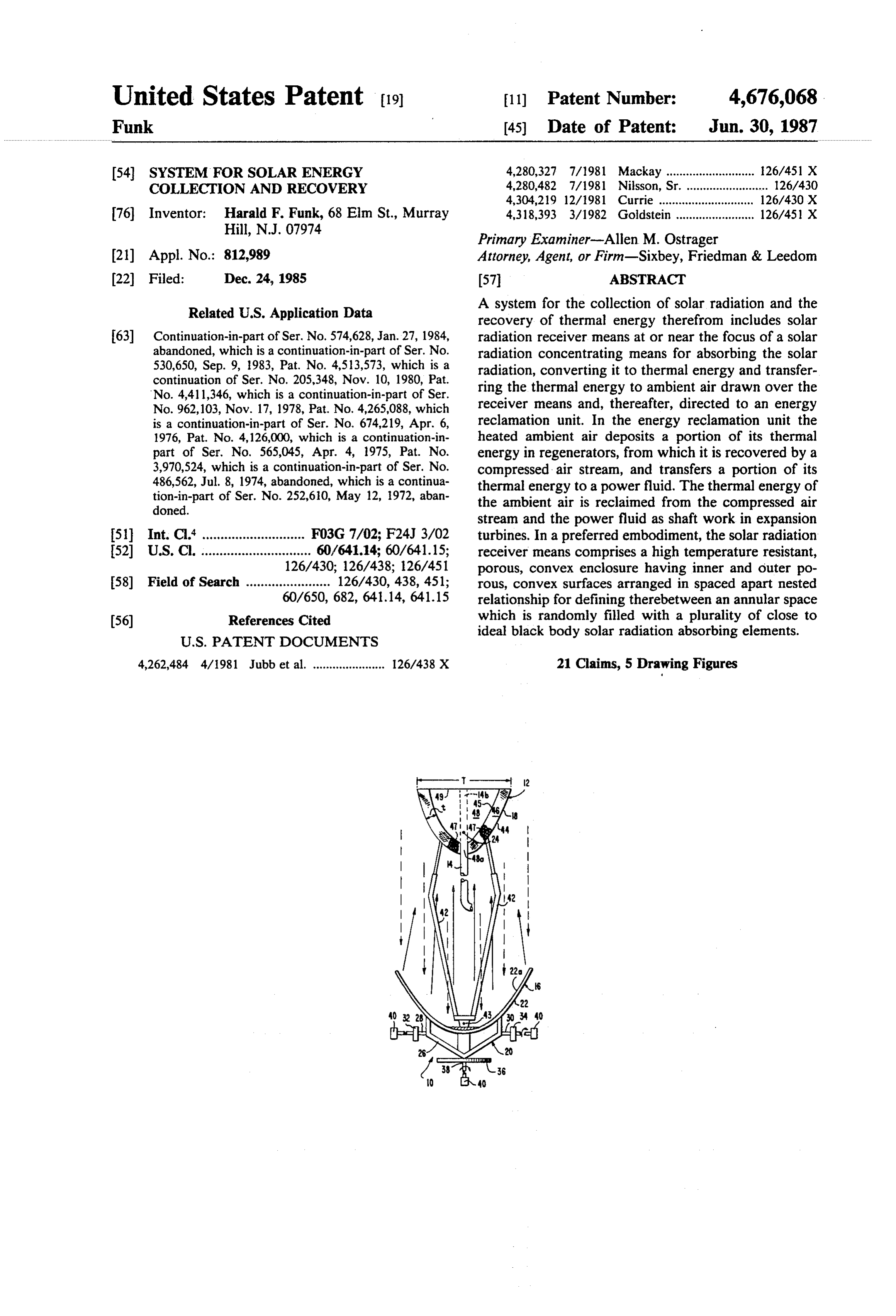
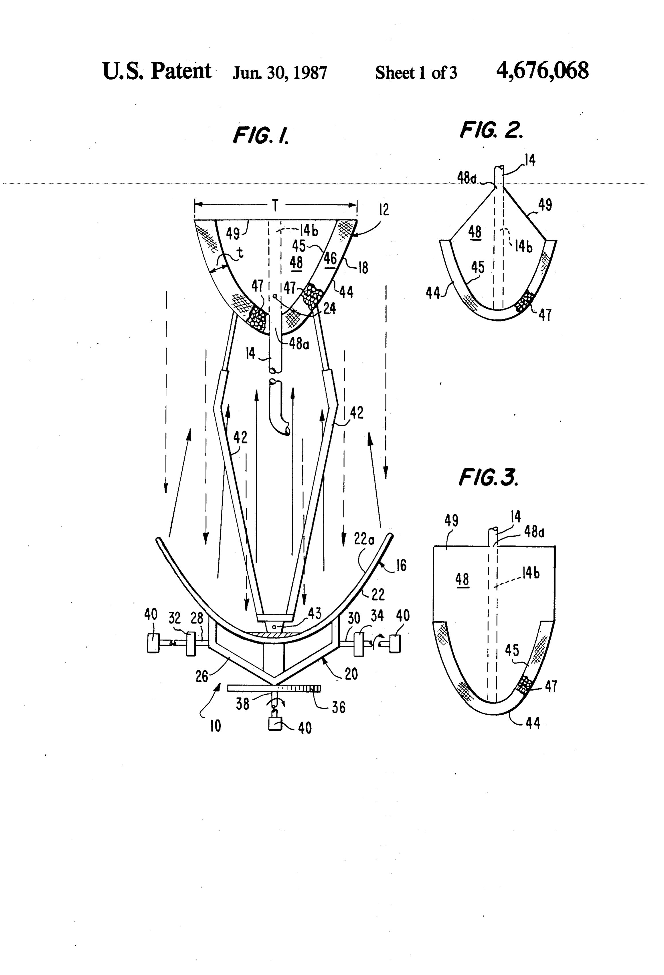
such as desert areas of the Middle East, or third world FIG. 1 is a front elevation, with portions broken countries in Africa. away, of a system for collecting solar radiation in accor It is therefore the purpose of the present invention to dance with the present invention.
overcome previously encountered difficulties and to FIG. 2 is a partial elevational view of one form of provide a thermally efficient and simple method and a solar radiation receiver means useful in the practice of lightweight, rugged, air transportable and easy to as 65 the present invention.
semble apparatus for the collection of solar radiation FIG.3 is a partial elevational view of another form of and the recovery of thermal energy therefrom. solar radiation receiver means useful in the practice of 3. Disclosure of the Invention the present invention.
Page 7
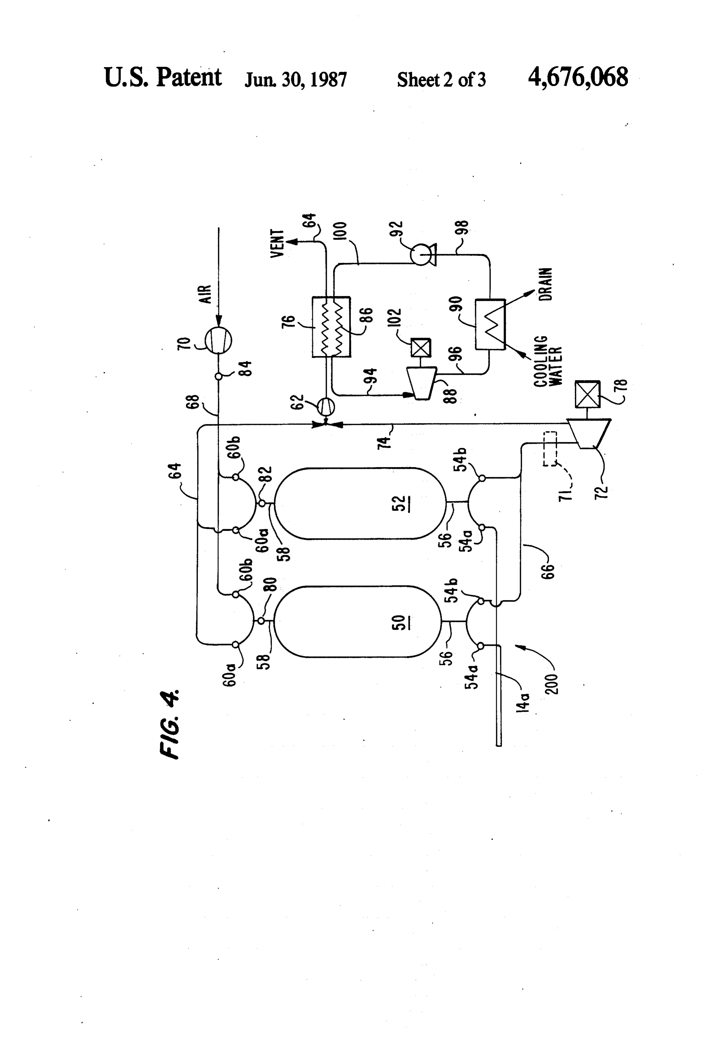
FIG. 4 is a schematic flow diagram of a system for bolic bowl 22 and/or in any radial direction about pivot recovering the thermal energy values from air heated to axis 43.
solar radiation in accordance with the present inven The incident solar radiation reflected by concentrat tion. ing means 16 impinges on and is absorbed by receiver FIG. 5 is a partial elevational view of another system 5 means 18 to convert the radiation to thermal energy, for collecting solar radiation in accordance with the heating the receiver means to the very high focus tem present invention. peratures, e.g., 1000-1200 C. The thermal conversion is direct and achieved principally by the mechanism of
BEST MODE FORCARRYING OUT THE radiation, which is essentially a surface phenomena. To INVENTION 10 achieve this in an efficient manner receiver means 18 Refering to FIG. 1, a solar radiation collection sys comprises a solar collector having a large surface area tem is indicated generally by the numeral 10. The sys and formed of or coated with a close to ideal black body tem 10 includes solar radiation collector unit 12 for material. Exemplary of such materials are certain ce absorbing solar energy and heating ambient air and 15 ramics, carbon such as graphite and lampblack, various ambient air conduit means 14 for directing the heated type paints, asbestos, brick, burnt clay, and the like. Desirable materials from the standpoint of emissivity ambient air from collector unit 12 to an energy reclama are materials having a total emissivity of 0.80 or better, tion unit (shown as 200 in FIG. 4) for recovering ther preferably 0.90 or better, at the focus temperatures. For mal energy values and reclaiming mechanical energy example, extremely values from the heated and compressed ambient air. 20 black having a total desirable materials include lamp emissivity of about 0.945 and red
Solar radiation collector unit 12 includes a solar radi ation concentrating means 16, such as a parabolic reflec brick mal having a total emissivity of about 0.93. The ther energy of the high temperature receiving means is tor, supporting a solar radiation receiver means 18, both transferred directly of which receiver and concentrating means are ceiving means 18 to toheat the ambient air adjacent the re the air, desirably via the heat mounted on sun tracking and mounting means 20 and 25 transfer mechanisms of radiation and convection. Heat move as a unit so that they are always directly pointed ing of the ambient air is also primarily a surface phe toward the sun. The solar radiation concentrating nomena and, to be efficient, the receiving means must means 16 consists of a parabolic reflector or mirror have a configuration which maximizes the surface area bowl 22, which is desirably formed in readily assembled in contact with the air in order to maximize heat trans sections for ease of transportation, by which incident 30 fer to the air.
solar radiation, indicated by dashed lines with arrow This is best accomplished, in accordance with the heads, is reflected from its inner surface 22a to a point at present invention, by providing a receiver means com its parabolic focus 24. The reflector or bowl 22 is prising a porous convex surface solar collector in which mounted on a suitable mounting and sun tracking means the convex surface curves outwardly toward parabolic 20 which can be rotated and tilted to vary the angle of is reflector 22. The porous surface may be a sheet having the reflector so that it directly faces the sun during the perforated openings therein but, more desirably, is a entire daylight hours. One suitable sun tracking means mesh or screen comprising a plurality of entwined comprises a framework 26 for mounting reflector or threads defining a plurality of open spaces between bowl 22 having a pair of diametrically extending axles adjacent threads. The collector comprises an outer po 28, 30 mounted in bearing standards 32,34. A rotary rous convex surface 44 and an inner porous convex table 36 supports framework 26 from its underside and surface 45 defining therebetween an annular space 46, includes a depending drive axle 38. Driving devices, most desirably of uniform cross-sectional configuration such as motors 40, are drivingly connected to axles 28, and dimensions. Filling the annular space 46 between 30 and 38 so that reflector 22 may be tilted about axles inner and outer surface 44, 45 are a plurality of ran 28, 30 and rotated with table 36. 45 domly arranged close-to-ideal black body elements 47 A solar radiation receiver means 18 is movably posi serving as the solar radiation absorbing surfaces of the tioned at the parabolic focus 24 in any conventional collector. The elements may be spherical, cylindrical, manner, such as on individually adjustable telescoping disc or saddle shaped (hollow or solid), pebbles, or any mounting braces 42 which are connected between re other high surface area configuration, regular or irregu ceiver 18 and inner surface 22a of reflector 22. Focusing 50 lar, suitable for filling annular space 46. In a preferred the incident solar radiation onto focus 24 concentrates form, the outer surfaces of the elements are roughened the solar energy at this point creating a heat sink region or porous to maximize the surface area available for in which the solar radiation receiver means 18 is posi radiation absorption and subsequent heat transfer. De tioned to absorb the incident solar radiation. Solar radi sirably, the mininum element dimension is at least : ation comprises electromagnetic waves beamed from 55 inch. Inasmuch as the space "t" between the inner and the sun and projected in a straight line to be converted outer surfaces 44, 45 is desirably at least 2 inches, the to heat when impinging upon the solar radiation re elements 47 desirably have no dimension exceeding ceiver means 18. Temperatures at focus 24 are typically inch. It will, of course, be appreciated that in larger very high, often in the range 1000 to 1200° C. or above, collectors where the space "t" between the inner and requiring a receiver means 18 which can withstand such outer surfaces is larger, the dimensions of the radiation high temperatures while, at the same time, efficiently absorbing elements may also be larger. function as a thermal collector and transferor of heat. The mesh forming the inner and outer collector sur Inasmuch as temperatures are highest at focus 24 it may faces 44, 45 serves only to retain and contain the radia at times be desirable to move receiver means 18 away tion absorbing elements 47 within the annular space 46. from the focus to decrease the temperature thereof. For 65 Therefore, the mesh spacing between adjacent mesh this purpose mounting braces 42 are telescopingly ad threads need be not much closer than the minimum justable for moving receiver means 18 toward and away element dimension. Indeed, it is desirable to minimize from focus 24, for example toward or away from para the amount of mesh on each surface in order to maxi
Page 8
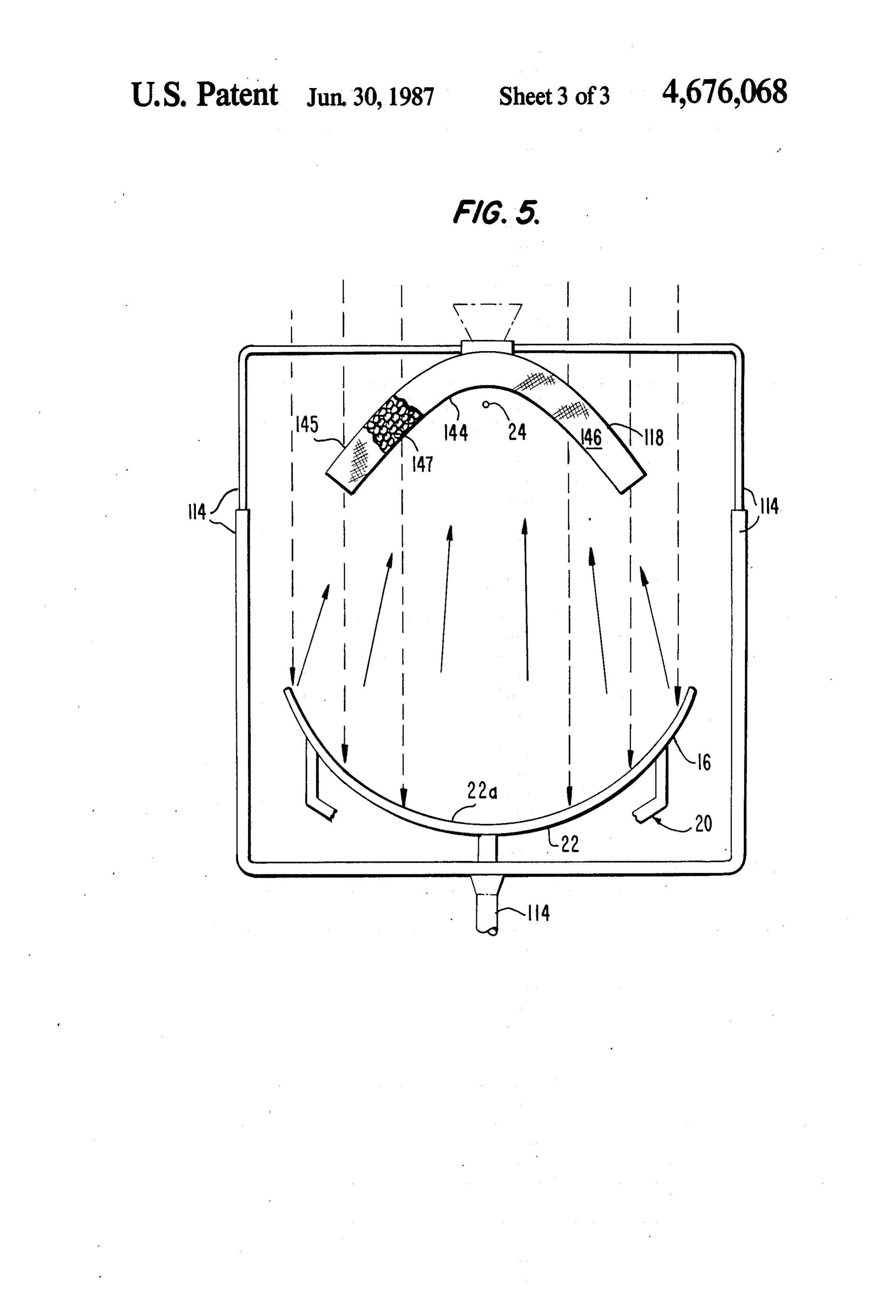
mize the amount of black body material directly ex except that outer surface 145 is solid rather than porous, posed to solar radiation. The mesh may be formed of allowing ambient air to be drawn through porous, con any material capable of withstanding the very high cave inner surface 144 and heated as it passes over and temperatures at the focus 24 without losing its ability to through elements 147 of the concave annular bed. retain the elements 47. As a practical matter, metals 5 Heated ambient air is ducted from annular space 146 of which can be readily and economically formed into receiver means 118 through ambient air conduit 114, mesh, such as stainless steel, e.g., SS 310, are most desir which may also serve as telescoping support braces for able. It will be apparent that the convex shape assumed supporting receiver means 118. Concave receiver by the mesh surfaces 44, 45 determines the convex means have the advantages that annular space 146 is shape assumed by the close-to-ideal black body element 10 more easily filled with black body elements 147, as via bed. This shape desirably, although not necessarily, a funnel (shown in phantom) for feeding such elements conforms to the shape of the reflector 22 and preferably into the top of the receiver means; the heated ambient is a shape which allows as much of the bed as possible air conduit means 114 readily serves the dual purpose of to be equidistant from the focus 24 in order that the conduit means and structural support elements; the reflected solar radiation is uniformly distributed over 15 concave configuration is better protected from environ the entire collector surface. To accomplish these pur mental damage and/or interference than is the convex poses convex shapes such as paraboloids, hemispheres, configuration, a feature which may be of significance hemispheroids, hemiellipsoids and hyperboloids, among when the receiver means is used in remote areas, such as others, are preferred. As a practical matter, in view of in deserts, and the like.
the preferred two inch minimum bed thicknesses, the 20 Heated ambient air is ducted from receiver means 18, maximum cross-sectional dimension "T', of these con 118 through ambient air conduit means 14 (which may vex shapes is at least about 1 foot, minimum dimensions include an apertured portion 14b within interior 48), 114 suitable for an approximately 10 kw unit. However, as into energy reclamation unit 200. Unit 200 is operable: will be appreciated, larger units containing larger beds (1) to cool the heated ambient air prior to ducting it to and increased air flow capabilities are capable of signifi 25 a thermal energy reclamation heat exchanger; (2) to cantly greater energy production. heat compressed air to within a few degrees of the tem Exemplary configurations meeting the foregoing perature of the ambient air which entered unit 200; and criteria are illustrated in FIGS. 1, 2 and 3 which show (3) to extract mechanical energy from the heated com is... collectors 18 having very large surface areas by virtue pressed air prior to ducting the compressed air to a - of the plurality of randomly arranged solar radiation 30 thermal energy reclamation heat exchanger. i-absorbing elements 47 housed between mesh surfaces Unit 200 includes two similar packed towers or col 44, 45 for defining a uniform thickness bed through umns 50, 52. Each of the towers 50, 52 is similar in which air is drawn and heated. The heated airflows into construction and content to the regenerator described the interior 48 of the collectors, defined between the by Russell B. Scott at pages 29-31 of Cryogenic Engi inner mesh surface 45 and removable insulating cover 35 neering, published in 1959 by D. Van Nostrand Co., 49. Cover 49 may be flat, as in FIG. 1 wherein the Princeton, N.J. Each of the towers contains loose is heated air is removed from the collector interior 48 solids, for example, ceramic balls, quartzite pebbles, : through an opening 48a in the convex bed surface. steel shot, etc., pancakes wound from thin corrugated - Cover 49 is desirably conical or cylindrical where, as in aluminum ribbon, or other solids having relatively large FIGS. 2 and 3, the heated air is removed through an surface area to volume ratios, relatively high heat ca opening 48a in cover 49 from the top of the collector pacitances and the capability of storing heat and resist - 'interior. ing corrosion. Typically, the packing for the regenera Heat transfer from receiver 18 to the ambient air is tor towers has a surface area to volume ratio and pack enhanced by causing air flow through the bed to follow ing capability sufficient that the regenerator has a sur the tortuous path between the randomly arranged ele 45. face of 1000 to 2000 square ft. per cubic foot. ments 47 and, by assuring the uniformity of the bed Automatic switch valves 54a, 54b are provided at the thickness "t' along the entire bed length in order to end of towers 50, 52 adjacent feed conduit, 14a. Feed prevent the air flow from finding a path of least resis conduit 14a connects with the valves 54a, Tower con tance. The air is heated in the bed in accordance with nection conduits 56 communicate the towers 50, 52 with the surface temperature of the elements 47 and the air 50 the valves 54a, 54b, Tower connection conduits 58 flow volume. It is noteworthy that it is only by virtue of communicate the towers 50, 52 with automatic switch utilizing randomly arranged solar radiation absorption valves 60a, 60b. Air feed line 68 and compressor 70 and heat transfer elements defining a tortuous air pas provide a compressed air flow through valves 60b into sage-type of configuration and exposing a large surface towers 50, 52 while heated air dischrge conduit 66 con area of the elements to solar radiation impingement and 55 nects with valves. 54b for providing a reclamation flow ambient air flow, that heat transfer by way of radiation path out of towers 50, 52 through expansion turbine 72 can be efficiently accomplished. Heat transfer by way and return line 74 to a point upstream of compressor 62 of conduction cannot be efficiently achieved using and reclamation heat exchanger 76. Compressor 62 is black body type materials and, therefore, configurations included in warm air discharge line 64 to provide the which include closed conduits for confined heat trans 60 suction for drawing ambient air through receiver means fer fluid flow are not desirable. 18 into conduit 14.
In some instances, where larger collectors are desired The manner by which heated ambient air is treated in the receiver means advantageously takes the form of a unit 200 may be visualized as that of subjecting the porous concave solar collector in which the hollow of ambient air in successive like cycles to cooling in towers the concavity faces toward the parabolic reflector. In 65 50, 52. During each cycle, a different step is being con this form of collector, as can be seen in FIG. 5, the ducted in each of towers 50, 52. While a first tower is structure of concave receiver means 118 is substantially serving as the cooling tower to cool the heated ambient the same as the structure of convex receiver means 18 air, the other tower is serving to heat the compressed air
Page 9
fed therethrough via air feed line 68. In the next cycle, ator to be blown back for purposes of cleaning and the roles of the respective towers are reversed. removal of undesirable contaminants. It also permits Thus in a first cycle one of the towers 50, 52 is se easier accessibility to the "hot" lines which must be lected as the cooling tower into which the heated ambi insulated. It is, of course, important to maintain the ent air is ducted and the corresponding valve 54a is temperature at the relatively cool end of the towers 50, opened. If tower 50 is to serve as the cooling tower, 52 at a constant level in order that the temperature of valve 54a associated therewith and valve 54b associated the compressed air from line 68 passed through the with tower 52 are opened while valve 54b associated tower to recover the heat energy stored therein from with tower 50 and valve 54a associated with tower 52 the previous cycle may be maintained at a temperature remain closed. The heated ambient air flows from feed 10 below that of the temperature at the relatively cool end conduit 14a through valve 54a upwardly into the bot of the tower. This can readily be achieved by position tom of tower 50 in which the ambient air is cooled. The ing temperatue sensors 80, 82 at the relatively cool end cooled, but still warm ambient air, exits from the top of of each tower 50, 52 and regulating the compression tower 50 via valve 60a and warm air discharge line 64, ratio in compressor 70 such that the compressed air is compressed in compressor 62, which desirably adds 15 temperature sensed at sensor 84 in air feed line 68 is heat values to the warm air, and passes to vent via recla below that of the temperatures sensed by sensors 80, 82. mation heat exchanger 76. Thus, compressor 62 may be The compressed air entering tower 52 via air feed line operated without the conventional after cooler in order 68 is heated in tower 52 to within 5 to 10 C. of the that the heat energy added to the warm ambient air by temperature of the heated ambient air entering tower the compressor is retained in the system and ultimately 20 50. Following expansion through expansion turbine 72 reclaimed. The heat values from the warm ambient air the turbine exhaust air is within the same general tem in line 64 may be discarded but, more likely, will be perature range as the warm ambient air at the relatively recovered or used in some manner, possibly for absorp cool end of towers 50, 52, i.e., about 225' to 240 C., at tion cooling. For example, the heat values may be trans which temperature it is admixed with the warm ambient ferred to a power fluid in reclamation heat exchanger 25 air exiting tower 50 and passed through compressor 62 76, as will be more fully described hereinafter, and and reclamation heat exchanger 76. The compressor reclaimed therefrom or this stream of warm ambient air increases the temperature of the air passing there can be used for an absorption cooling system. At the through by about 25 to 40 C. while the reclamation same time the tower 50 is heated by the ambient air heat exchanger reduces the temperature of the air exit passing therethrough in preparation for serving as the 30 ing therefrom to about 80 C. or below, at which tem compressed air heating tower in the next cycle. perature very little recoverable thermal energy is The heat energy stored in tower 52 is recovered by wasted by venting the air stream.
passing compressed air through air feed line 68 into and The next cycle is like the one just described except downwardly through tower 52 in which the air is that tower 52 now serves as the heated ambient air heated while the tower is cooled (it is assumed that 35 cooling tower and tower 50 as the compressed air heat tower 52 had been pre-heated in a previous cycle by ing tower. It will be appreciated that following the passage of heated ambient air therethrough). The previous cycle, tower 50 was left in a relatively heated heated compressed air leaves the bottom of tower 52 by state by the passage of heated ambient air therethrough way of tower connection conduit 56 through valve 54b whereas tower 52 was left in a relatively cooled state by and heated air discharge conduit 66. The energy con virtue of having given up its heat content to the com tent may be reclaimed from the heated compressed air pressed air passing therethrough. In this next cycle the stream by passing the stream through expansion turbine heated ambient airflows from feed conduit 14a through 72 to cool the compressed air by substantially isentropic valve 54a into tower 52 in which the heated ambient air expansion while at the same time producing shaft work. is cooled while the tower is heated. The cooled, but still To convert the shaft work to a more useful form of 45 warm ambient air, exiting tower 52 is then ducted via energy, a power generator 78 is coupled to the drive warm air discharge line 64 to compressor 62 in which it shaft of the turbine 72. A filter means 71, such as a is compressed prior to relinquishing the major portion cyclone or screen, may be inserted in heated air dis of its thermal values in reclamation heat exchanger 76. charge conduit 66 upstream of turbine 72 to remove any The compressed air entering tower 50 via air feed line solid particulate matter which may be picked up by the 50 68 is heated while the tower is cooled and the resulting compressed air stream from the tower packing. The heated air leaving tower 50 via heated air discharge cooled, but still warm air exhausting turbine 72 is conduit 66 is expanded and cooled through expansion ducted via return line 74 to warm air discharge line 64 turbine 72 and then admixed with the warm ambient air upstream of compressor 62, at which point it is admixed in line 64 upstream of compressor 62 prior to thermal with the warm ambient air exiting tower 50. The result 55 reclamation in reclamation heat exchanger 76. ing combined warm air stream is compressed in com One means for reclaiming the heat energy contained pressor 62, transfers a portion of its heat values to a in the warm ambient air exiting compressor 62 com power fluid in reclamation heat exchanger 76 and passes prises passing the air through reclamation heat ex to Vent, changer 76 wherein it gives up its heat energy to a In a typical system the heated ambient air entering power fluid which, in turn, operates as the fluid in a cooling tower 50 is at a temperature of about 450 to Rankine cycle engine to do useful work. Heat ex 550' C. and is cooled in the tower to about 225' to 240 changer 76 may be of any conventional type useful to C. In a unit intended to be readily transportable, assem transfer heat energy to a power fluid and may be either bled on-site and used in remote areas it is particularly a single or multiple stage unit. As the air passes through desirable to depart from conventional arrangements and 65 the heat exchanger 76 it sacrifices sensible heat to the to orient the regenerators with the hot (heated ambient power fluid which circulates in coils 86. The power air entering) end at the bottom as shown. Such an ar fluid which is heated by the warm ambient air passing rangement allows any sand or dirt entering the regener through heat exchanger 76 is used to perform useful
Page 10
work. In the preferred embodiment, the heat exchanger a Rankine cycle engine. The power fluid is pumped coils 86 form the boiler of an external conmbustion through the closed cycle at an expense of 2 Kwh but engine. Such an engine typically includes an expansion expands in passing through expansion turbine 88 to turbine 88, a condenser 90, and a pump 92, connected in drive a generator to yield about 28 Kwh. series by conduits 94, 96, 98, 100. Power fluid heated Recognizing that the solar energy input to the system during passage through the coils 86 is expanded in the is free and therefore need not be considered in an eco turbine 88 and serves to drive a generator. The power nomic energy balance, the energy balance for the sys fluid is then ducted through the condenser 90 and the tem is as follows:
pump 92 for return to the heat exchanger coils 86. It should be appreciated that the Rankine cycle compo O INPUT OUPUT ments reduce the portability of the system and may advantageously be deleted on mobile units where trans Compressor (70) 56 Kwh Expansion turbine (72) 87 Kwh portability and like characteristics are of paramount Compressor (62) 14 Kwh Expansion turbine (88) 28 Kwh importance. In such units the warm air is discharged Pump (92) 2. Kwhl.
through line 64. 15 TOTAL 72 Kwh TOTAL 15 Kwh The invention will be better understood by reference to the following example which is illustrative of the Even considering the solar energy input of 110 Kwh, operation of the method and system of the present in the overall system efficiency is 115 Kwh output vs. 182 vention. Kwh input, an overall recovery efficienty greater than
EXAMPLE 60%. Viewed in another manner, the net energy recov A parabolic dish solar reflector having a diameter of ery is 115-72=43 Kwh, yielding a net efficiency of 10 meters is capable of reflecting solar radiation under about 40%, which is still excellent. optimum conditions at the rate of 1400-watts/m2-hr, INDUSTRIAL APPLICABILITY providing a capacity of 110 kw/hr (Kwh). A parabolic 25 The method and apparatus of the present invention solar collector having an outer diameter of about 0.67 for the collection of solar radiation and the recovery of meters and inner and outer mesh surfaces defining a 3 thermal energy therefrom is efficiently and broadly inch wide annular space therebetween containing :- inch diameter irregularly surfaced, generally spherical applicable able uses, to the production of energy for all conceiv industrial, agricultural, utility, and the like.
ceramic balls formed of burnt clay and graphite, similar 30 The system is useful anywhere to the collector of FIG. 2, is positioned at the parabolic sunlight and air. In particular,where the there is access to present system is focal point. By utilizing the suction side of compressor formed of rugged, compact, air transportable, 62 to draw a flow of ambient air through the 3 inch mountable, air droppable components susceptibleskid thick bed of ceramic balls and over the large surface ready on-site assembly. Therefore, it is ideal for use to in area defined thereby to exchange heat between the high 35 remote areas for providing power to operate irrigation temperature ceramic balls and the ambient air, a heated and/or drinking water pumps or to generate electricity. ambient air flow of 700 Nm/hr (normal cubic meter It is also ideal for providing emergency power in devas per hour) at 500 C. is established through ambient air conduit 14 and feed conduit 14a. The heated ambient air tated areas struck by natural disasters such as flood, flows through regenerator tower 50 to deposit heat on 40 earthquake and the like. The system of the present in vention is particularly unique in providing an energy the solid materials therein. Warm ambient air exits tower 50 at about 230 C, storage capability heretofore only available using large, While regenerator tower 50 is heating up, regenera unwieldy and untransportable pebble beds or by con tor tower 52 (pre-heated in a previous cycle) is charged verting thermal energy to mechanical energy for pump with 700 Nm/hr of air which has been compressed. 45 ing water into a water tower or elevated reservoir and from 1 BAR and 40 C. to about 5 BAR. and 222 C. is storing the energy in the form of potential energy of compressor 70. The work of compression requires water. According to the present invention, the close to about 56 Kwh. The compressed air flows through re ideal black body radiation absorbing elements function generator tower 52 to withdraw heat from the solid in a manner similar to pebble bed storage sites in retain materials therein. Hot compressed air at about 490 C. 50 ing thermal energy for a prolonged period until there is exits tower 52 and is ducted to and through expansion a need for the energy, at which time ambient air may be turbine 72 wherein the hot compressed air is expanded drawn through and over the elements, as hereinbefore to about 1.0 BAR and a temperature of about 225 C. described, to transfer the thermal energy to the ambient The expansion turbine drives a generator to yield about air for utilization. Another 'built-in' form of thermal 87 Kwh. The cooled turbine exhaust at about 225 C. is 55 storage inherent in the present system are the regenera admixed with the warm ambient air exiting tower 50 tor towers which will maintain their temperatures for and the combined 1400 Nm3/hr air flow at about 225' about 48 hours, allowing minimum start-up time when -230 C, is compressed in compressor 62 to a pressure of ever energy production is required and possible. Both about i. 1 BAR and a temperature of about 254 C. the the solar collector bed elements and the regenerator compression work requies about 14 Kwh. After passing 60 towers allow energy generated during sunlight hours to through reclamation heat exchanger and transferring a be stored as thermal energy for long periods of time and major portion of its thermal energy to a powerfluid, the used whenever solar collection and conversion is not combined air flow exits the heat exchanger at about 80 feasible, such as during nighttime hours. C. and is vented. What is claimed is:
The heat lost by the combined air stream in cooling 65 1. An apparatus for the collection of solar radiation from 254 C. to 80' C. in the reclamation heat ex and the recovery of thermal energy therefrom compris changer causes a corresponding heat gain by the power ing solar radiation collection means and energy recla fluid circulating through the coil thereof as the fluid in mation means,
Page 11
said solar radiation collection means including solar 8. An apparatus, as claimed in claim 7, including radiation receiver means comprising a close to means for moving said receiver means relative to said ideal black body solar collector and solar radiation focal point.
concentrating means, said concentrating means 9. An aparatus, as claimed in claims 2 or 4, wherein comprising reflector means for focusing incident 5 said means for reclaiming the energy of said heated solar radiation onto a heat sink region in which said ambient air comprises;
black body collector is positioned for absorbing the first heat exchange means for passing said heated incident solar radiation and converting said radia ambient air into direct heat exchange relationship tion to thermal energy substantially completely by with a relatively high heat capacitance solid mate radiation whereby the temperature of said collec O rial to exchange heat between said heated ambient tor is increased, said solar collector comprising a air and said solid material and concurrently cool high temperature resistant, porous enclosure hav said ambient air and heat said solid material; ing inner and outer surfaces arranged in spaced conduit means in air flow communication with said apart nested relationship for defining therebetween 15 collector and said means for causing ambient air an annular space, a plurality of close to ideal black flow for directing said heated ambient air from said body, a high surface area solar radiation absorbing collector to said first heat exchange means; elements randomly filling said annular space, at second heat exchange means for passing compressed least said inner surface being porous for allowing air into direct heat exchange relationship with a ambient air to flow therethrough into heat transfer 20 relatively high heat capacitance solid material to relationship with said elements, the openings in exchange heat between said compressed air and said porous surface being smaller than the mini said slid material, whereby compressed air is passed mum dimension of said elements for retaining said through said second heat exchange means to con elements within said annular space, said elements currently cool said solid material and heat said defining an annular-bed having a tortuous path for 25 compressed air; and air flow therethrough onto which solar radiation expansion turbine means for expanding said heated impinges for increasing the temperature of said bed compressed air to produce shaft work whereby and from which thermal energy is transferred to cooled air exits said turbine means. ambient airflowing from outside said bed via tortu 10. An apparatus, as claimed in claim 9, wherein said ous path through said bed for heating said ambient 30 first and second heat exchange means are arranged in alr; parallel relationship and including means for directing said energy reclamation means including means for said heated ambient air and said compressed air, alter causing a flow of ambient air through said bed into nately, to said first and second heat exchange means direct heat transfer relationship with the said in whereby said heated ambient air is directed to said heat creased temperature surfaces of said collctor for 35 exchange means containing relatively cool solid mate heating the ambient air, the energy transfer to said rial and said compressed air is directed to said heat ambient air occurring substantially completely by exchange means containing relatively hot solid mate radiation and convection, means for reclaiming rial.
thermal energy from said heated ambient air, 11. An apparatus, as claimed in claim 10, wherein whereby said heated air is cooled, and means for each of said heat exchange means comprises a regenera directing a flow of heated ambient air from said tor tower containing said relatively high heat capaci collector to said reclamation means. tance solid material.
2. An apparatus, as claimed in claim 1, wherein said 12. An apparatus, as claimed in claim 11, wherein said porous enclosure is convex, said inner and outer sur regenerator towers are oriented with said heated ambi faces are porous and convex and said elements define a 45 ent air receiving portion thereof arranged below said convex annular bed through which said ambient air compressed air receiving portion.
flows into the interior of said collector, said solar col 13. An apparatus, as claimed in claim 10, further lector being oriented with said convex surfaces curving including warm air heat reclamation means in air flow outwardly toward said reflector means. communication with said first and second heat ex 3. An apparatus, as claimed in claim 2, wherein said 50 change means and said expansion turbine means for inner and outer surfaces comprise high temperature receiving the cooled ambient air exiting each of said resistant mesh and said elements comprise spheres. heat exchange means and the cooled compressed air 4. An apparatus as claimed in claim 1, wherein said exiting said gas turbine means for recovering at least a porous inner surface is concave, said solar collector portion of the thermal energy content of said cooled air being oriented with the hollow of said concave surface 55 Streans.
facing toward said reflector means. 14. An apparatus, as claimed in claim 13, wherein said 5. An apparatus, as claimed in claims 2 or 4, wherein warm air heat reclamation means comprises means for said receiver means is mounted to said concentrating passing said cooled air streams into heat exchange rela means for unitary movement of both as said concentrat tionship with a powerfluid whereby at least a portion of ing means is moved for tracking the position of the sun. the thermal energy in said cooled air streams is trans 6. An apparatus, as claimed in claim 5, including ferred to said power fluid for concurrently heating said means for moving said receiver means relative to said power fluid and further cooling said cooled air streams. concentrating means. 15. An apparatus, as claimed in claims 2 or 4, wherein 7. An apparatus, as claimed in claims 2 or 4, wherein said means for causing ambient air flow comprises com said concentrating means comprises parabolic reflector 65 pressor means in air flow communication with said means for reflecting incident solar radiation and con collector.
centrating said radiation at the focal point of said reflec 16. An apparatus, as claimed in claim 15, wherein said tor means. compressor means includes a compressor operable to
Page 12
compress said cooled air stream at a point downstream (c) reclaiming thermal energy from said heated ambi of said collector. ent air.
17. A method for the collection of solar radiation and 18. A method, as claimed in claim 17 wherein the step the recovery of thermal energy therefrom, comprising of reclaiming thermal energy includes the steps of: 5 passing said heated ambient air through a heat ex (a) focusing solar radiation on and transferring, sub change zone in direct heat exchange relationship stantially completely by radiation, solar energy to with a relatively high heat capacitance solid mate solar radiation receiver means for increasing the rial to concurrently cool said ambient air and heat said solid material;
temperature of said receiver means, said focusing O recovering being accomplished by providing reflector means at least a portion of the thermal energy of for focusing incident solar radiation onto a heat the heated ambient airby passing compressed air in sink region in which said receiver means is posi direct heat exchange relationship with said heated tioned, said solar energy transfer to said receiver solid material to concurrently cool said solid mate means comprising providing a high temperture 15 expanding rial and heat said compressed air; and resistant, porous enclosure having inner and outer said heated compressed air through an surfaces arranged in spaced apart nested relation expansion turbine means for producing shaft work and a cooled air stream.
ship for defining therebetween an annular space, a 19. A method, as claimed in claim 18, wherein said plurality of close to ideal black body, high surface heat exchange zone comprises first and second heat area solar radiation absorbing elements randomly 20 exchange sub-zones arranged in parallel relationship filling said annular space, at least said inner surface and said heated ambient air is passed, alternately, being porous for allowing ambient air to flow through said first and second sub-zones, said thermal therethrough into heat transfer relationship with energy from said first sub-zone being recovered by said said elements, the openings in said porous surface compressed air while said heated ambient air is passed being smaller and the minimum dimension of said 25 through said second sub-zone.
elements for retaining said elements within said 20. A method, as claimed in claim 9, wherein said annular space, said elements defining an annular cooled ambient air stream exiting said heat exchange bed having a tortuous path for air flow there Zone and said cooled compressed air stream exiting said through onto which solar radiation impinges for gas turbine means are passed in heat transfer relation increasing the temperature of said bed and from 30 ship with a power fluid whereby at least a portion of the which thermal energy is transferred to ambient air thermal energy remaining in said cooled air streams is flowing via said tortuous path through said bed for transferred to said power fluid for concurrently heating heating said ambient air; the power fluid and further cooling said cooled air (b) causing a flow of ambient air into heat exchange streams.
relationship with said increased temperature sur 35 21. An apparatus, as claimed in claims 1, 2 or 4, faces of said collector and transferring, substan wherein said close to ideal black body elements have an tially completely by radiation and convection, emissivity of at least 0.80 at the heat sink region temper thermal energy to said ambient air for producing atures. k is st k sk heated ambient air; and
Provenance
- Collection
- Cited prior art
- Original PDF
- patentimages.storage.googleapis.com →
- Filed
- 1985-12-24
- Pages
- 12
- Method
- pdftotext (the PDF's own text layer) + pdftoppm 300dpi page scans
- Source
- Google Patents bibliographic record
- Granted
- 1987-06-30
- Inventors
- Harald F. Funk
- Transcribed from
- patentimages.storage.googleapis.com →