patent · US4671351
Fluid treatment apparatus and heat exchanger
9 June 1987
Page 1 — bibliographic record
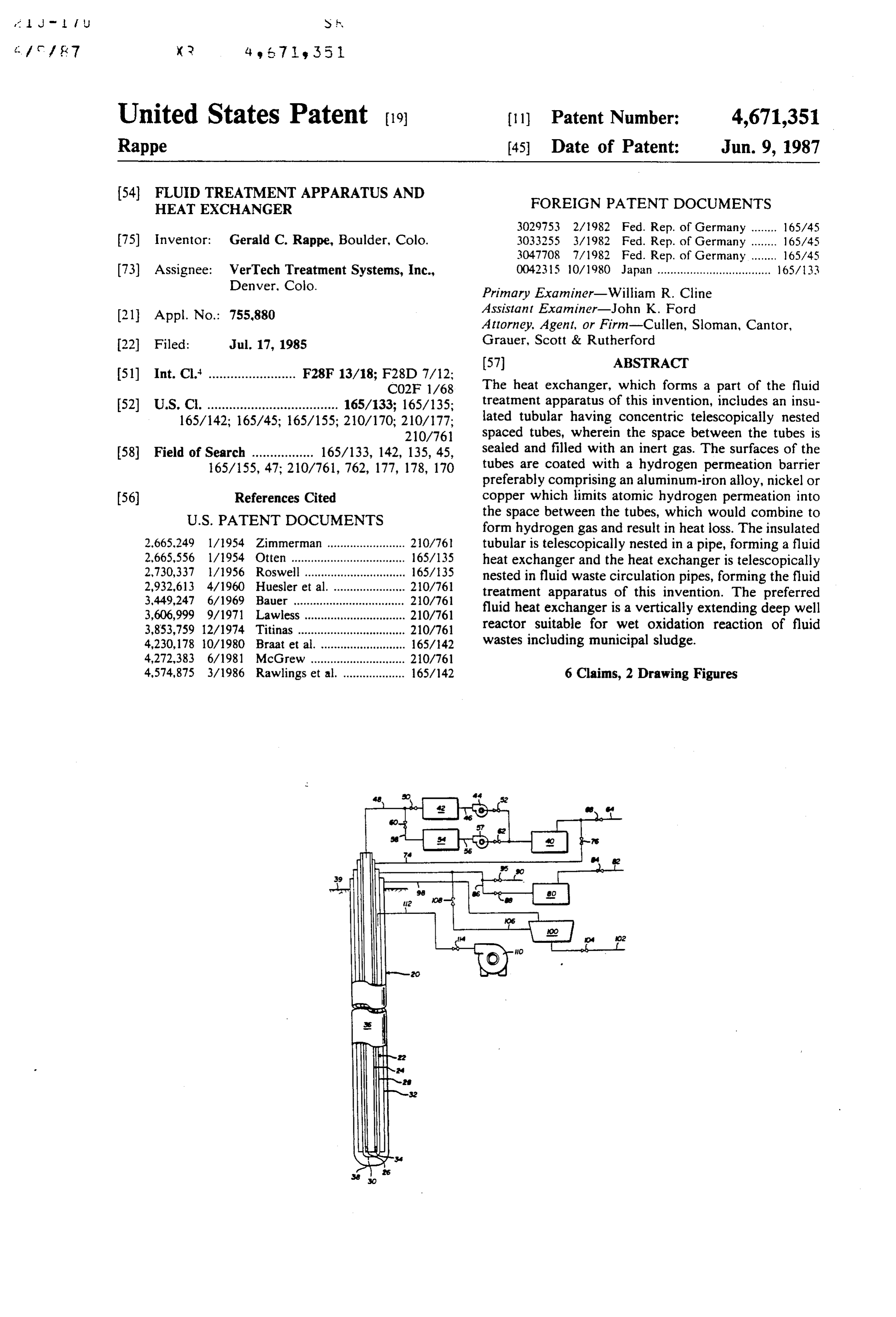
United States Patent (19) (11) Patent Number: 4,671,351 Rappe (45) Date of Patent: Jun. 9, 1987 (54) FLUID TREATMENT APPARATUS AND FOREIGN PATENT DOCUMENTS
HEAT EXCHANGER
75) Inventor: Gerald C. Rappe, Boulder, Colo. 3033255 3/1982 Fed. Rep. of Germany ........ 165/45
(73) Assignee: VerTech Treatment Systems, Inc., 0042315 10/1980 Japan ................................... 165/33 Denver, Colo.
Primary Examiner-William R. Cline
Assistant Examiner-John K. Ford (21) Appl. No.: 755,880 Attorney, Agent, or Firm-Cullen, Sloman, Cantor, 22) Filed: Jul. 17, 1985 Grauer, Scott & Rutherford
51) Int. Cl." ........................ F28F 13/18; F28D 7/12:
CO2F 1/68 The heat exchanger, which forms a part of the fluid 52 U.S. Cl. .................................... 165/133; 165/135; treatment apparatus of this invention, includes an insu 165/142; 165/45; 165/155; 210/170; 210/177; lated tubular having concentric telescopically nested 210/76 spaced tubes, wherein the space between the tubes is 58) Field of Search ................. 165/133, 142, 135, 45, sealed and filled with an inert gas. The surfaces of the 165/155, 47; 210/761, 762, 177, 178, 170 tubes are coated with a hydrogen permeation barrier preferably comprising an aluminum-iron alloy, nickel or (56) References Cited copper which limits atomic hydrogen permeation into
form hydrogen gas and result in heat loss. The insulated 2,665.249 1/1954 Zimmerman ........................ 20/76 tubular is telescopically nested in a pipe, forming a fluid 2,665,556 1/1954 Otten ............. ... 165/135 heat exchanger and the heat exchanger is telescopically 2,730,337 l/1956 Roswell ......... ... 165/135 nested in fluid waste circulation pipes, forming the fluid 2,932,613 4/1960 Huesler et al. ... 20/761 treatment apparatus of this invention. The preferred 3,449,247 6/1969 Bauer ............ ... 20/761 fluid heat exchanger is a vertically extending deep well
3,853,759 12/1974 Titinas....... ... 210/761 reactor suitable for wet oxidation reaction of fluid 4,230,178 10/1980 Braat et al. ........ ... 165/42 wastes including municipal sludge.
4,574,875 3/1986 Rawlings et al. ................... 165/142 6 Claims, 2 Drawing Figures
Page 2
Drawing sheet — no readable text.
Page 3
Compressed air is injected into the downwardly flow
FLUID TREATMENT APPARATUS AND HEAT ing sludge preferably in the form of Taylor-type gas EXCHANGER bubbles. In the McGrew patent, the temperature of the
reaction is controlled by a heat exchanger jacket which surrounds the inner concentric pipes wherein heated oil 1. Field of the Invention or other heat exchange fluid is pumped into the jacket This invention relates to an improved insulated tubu to control the temperature of the reaction zone. lar and heat exchanger and a continuous fluid treatment The fluid treatment apparatus of this invention pref. apparatus such as may be used in down-hole wet oxida 10 erably utilizes a centrally located heat exchanger tion of fluid waste streams, including municipal sludge. wherein the fluid to be treated is contained within recir 2. Description of the Prior Art culating pipes which surround the heat exchanger, re Above ground wet oxidation systems have been in sulting in better control of the temperature of the reac use for several years with limited success for the treat tion zone and more efficient heating of the fluid to be ment of municipal sludge received from a sewage treat 15 treated. The center downconner pipe of the heat ex ment process. The above-ground wet oxidation systems changer is preferably an insulated tubular which com use high surface pressure and heat to initiate the wet prises two concentric pipes or tubes telescopically oxidation reaction, however, the apparatus is not en nested in spaced relation wherein the space between the ergy efficient, the system is subject to failure and results tubes is sealed and preferably filled with an inert gas. As in only partial oxidation of the sludge; see for example, 20 will be understood, the pipes and insulated tubular used U.S. Pat. No. 2,665.249 of Zimmermann and U.S. Pat. in the fluid treatment apparatus of this invention con No. 2,932,613 of Huesler, et al. The above ground wet prises a series of pipes interconnected in a vertical string oxidation processes have not therefore replaced the to accommodate the length of the overall fluid treat traditional methods of treating municipal sludge, which ment apparatus. Insulated tubulars have been used in the includes settling, dewatering, drying, incineration and the like. 25 oil well industry and other industries for several years Various vertical or down-hole fluid treatment sys to transfer heated fluids and gases. As set forth herein tems have been proposed by the prior art but are used below, however, the fluid treatment apparatus of this only in very limited applications. A down hole fluid invention requires localizing the heat as much as possi treatment system utilizes vertical pipes which generally ble in the reaction zone located adjacent the bottom of extend downwardly into the ground from a control 30 the pipes. The heated oil or other heat transfer fluid is station. The fluid to be treated is pumped into the verti received at the top of the apparatus or ground level. cal reactor pipes and the fluid head creates a pressure Thus, radial heat losses through the insulated tubular to which assists in the desired fluid process or reaction. In the recirculated heat transfer fluid must be minimized. the processes used to date, the reaction requires addi It has now been found that a substantial heat loss results tional heat which may be added by electrical resistance 35 from atomic hydrogen permeation into the space be coils or heated fluid which circulates in a heat ex tween the tubes of the insulated tubular which recom changer. Air or other gases may be added to the fluid bines to form gaseous hydrogen. There is therefore a being treated to assist in the reaction. need to develop an improved insulated tubular which Although several prior art patents propose a vertical inhibits hydrogen permeation to improve the insulation well wet oxidation reaction system for treatment of 40 municipal sludge or other fluid waste streams, the pro qualities improved of the insulated tubular which results in an heat exchanger and fluid treatment apparatus cesses and apparatus disclosed in these patents have not of the type disclosed herein.
been successful; see for exapmle U.S. Pat. No.
3,449,247. As recognized by these prior art patents, the SUMMARY OF THE INVENTION pressure created by the fluid head is dependent upon the 45 As described, the heat exchanger and insulated tubu length of the reactor. Thus, it is theoretically possible to lar of this invention is particularly, although not exclu fully oxidize municipal sludge at a depth of approxi sively, adapted to utilization in a fluid treatment appara mately one mile provided the concentration of the oxi dizable material in the municipal sludge is balanced tus for continuous treatment of fluid waste at elevated against the oxygen available in the air injected into the 50 temperatures and pressures, such as down-hole fluid system. To the applicant's knowledge, however, no one treatment apparatus including wet oxidation of munici has been successful in building a down-hole wet oxida pal sludge and other fluid wastes. The preferred heat tion system for municipal sludge except the assignee of exchanger includes an elongated insulated tubular pref the present invention. erably having an open end which is generally concen U.S. Pat. No. 4,272,383 of Dr. McGrew, entitled 55 tric with and telescopically nested in a second pipe "Method and Apparatus for Effecting Subsurface, Con preferably having a closed end adjacent the open end of the surrounding pipe to communicate with the insulated trolled, Accelerated Chemical Reactions', assigned to tubular.
the assignee of the present invention, discloses the prin The insulated tubular includes a first inner tube ciples of the first successful down-hole wet oxidation and a second outer tube which is preferably generally reaction system for municipal sludge which is now concentric with and surrounds the first tube in spaced operating on an experimental basis in Longmont, Colo relation. The space between the first and second tubes is rado. The apparatus disclosed in the McGrew patent preferably sealed and filled with an inert gas, such as includes a series of generally concentric telescopically argon, helium or xenon. The heat transfer fluid such as nested pipes or tubes wherein diluted municipal sludge oil is received in the first inner tube of the insulated is preferably received in the inner pipe and flows down 65 tubular preferably at an elevated temperature. The heat wardly to a reaction zone adjacent the bottom of the transfer fluid then flows through the insulated tubular pipe and recirculated upwardly through a second pipe, and returns through the annular space between the which surrounds the inner pipe, following the reaction. outer tube of the insulated tubular and the downcomer
Page 4
pipe containing fluid and oxidizing gas for heating and aluminum alloy coating has been found to be particu recirculation. larly effective in preventing diffusion of atomic hydro In the most preferred embodiment of the heat ex gen into the sealed space between the tubes. The diffu changer, the insulated tubular includes a hydrogen per sion barrier may also be formed by electroplating cop meation barrier on the inner and outer surfaces of both 5 per or preferably nickel on the surfaces of the tubes. As tubes of the insulated tubular. The hydrogen perme described, the diffusion of atomic hydrogen into the ation barrier is preferably formed by coating the inner sealed space between the tubes of the insulated tubular and outer surfaces of the tubes with aluminum, nickel or results in an increased thermal conductivity and resui copper. The permeation barrier reduces the flow of tant increased radia heat losses from the heat transfer atomic hydrogen into the space between the first and () fluid flowing through the insulated tubular to the recir second tubes of the insulated tubular, thereby reducing culating heat transfer fluid in the second outer pipe of heat losses from the hot transfer fluid in the center tube the heat exchanger.
of the insulated tubular to the returning heat transfer The method of forming an insulated tubular for use in fluid in the annular region whose inner surface is the a heat exchanger apparatus, as described, thus includes outer surface of the insulated tubular. When the heat forming the telescopically nestable tubes, forming a exchanger of this invention is submerged in a fluid, the hydrogen permeation barrier coating on the exterior heat transfer is concentrated in a reaction zone located and interior surfaces of the tubes and assembling the adjacent the end of the heat exchanger, which is partic tubes in nested, concentric, telescopically spaced rela ularly advantageous in the down-hole fluid treatment tion and sealing the space between the tubes. The space apparatus of this invention. The elongated fluid heat 20 between the tubes is then evacuated and preferably exchanger is then surrounded by circulation pipes con filled with an inert gas. In the most preferred method of taining the fluid to be treated. The circulation pipes forming the insulated tubular of this invention, the hy include a first pipe which telescopically surrounds the . drogen permeation barrier coating is formed by diffu outer pipe of the heat exchanger in spaced relation sion coating the interior and exterior surfaces of the which receives the fluid to be treated in contact with 25 tubes with aluminum, forming an iron-aluminum alloy the outer pipe of the heat exchanger. A second pipe on the surfaces. As described, the hydrogen permeation generally concentric with and surrounding the first pipe barrier may also be formed by electroplating the sur receives the treated fluid. The fluid to be treated, such faces with nickel or the barrier may also be formed by as municipal sludge or other fluid waste is received electroplating copper on the surfaces. between the outer pipe of the heat exchanger and the 30 Other advantages and meritorious features of this first pipe of the fluid circulation pipes. The fluid to be invention will be more fully understood from the fol treated flows through the first pipe in contact with the lowing description of the preferred embodiments, the heat exchanger and recirculates through the second appended claims, and the drawings, a brief description outermost pipe. In this embodiment, the fluid treatment of which follows.
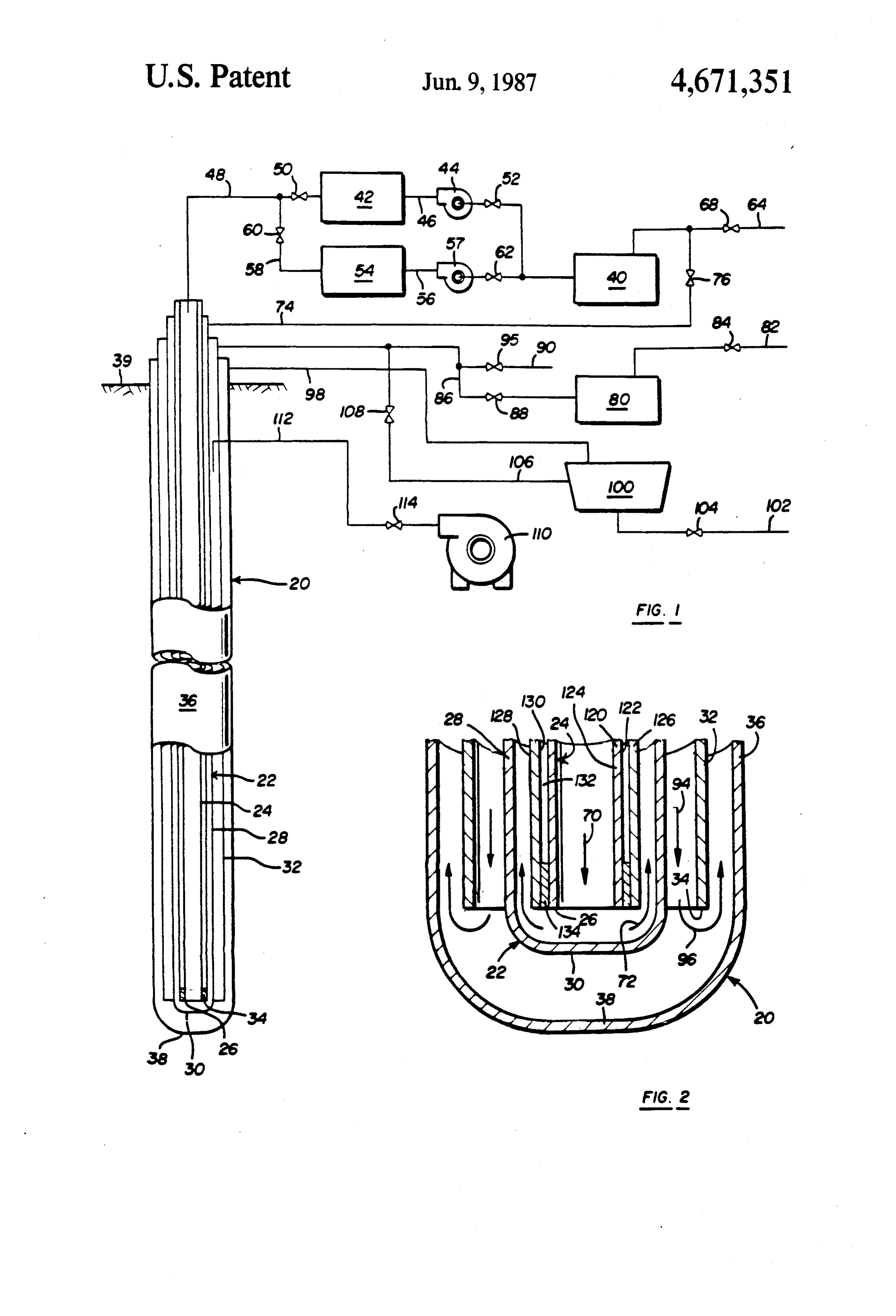
apparatus thus creates a fluid reaction zone adjacent the 35 BRIEF DESCRIPTION OF THE DRAWINGS end of the fluid circulation pipes.
As described, the fluid treatment apparatus of this FIG. 1 is a schematic illustration of a preferred em invention is particularly suitable for continuous treat bodiment of the continuous fluid treatment apparatus of ment of fluid waste including municipal sludge and this invention; and contaminated fluid waste at elevated temperatures and FIG. 2 is a cross-sectional view of the lower portion pressures. Where the fluid treatment apparatus is uti of the fluid treatment apparatus shown in FIG. 1. lized to treat municipal sludge and other waste by wet DESCRIPTION OF THE PREFERRED oxidation, the fluid treatment apparatus comprises a EMBODIMENTS AND METHOD OF THIS plurality of elongated generally concentric and tele INVENTION scopically nested pipes which extend vertically into the 45 ground as much as a mile or more in depth. The central The continuous fluid treatment apparatus 20 illus insulated tubular, which receives the hot heat transfer trated in the drawings is a vertical down hole fluid fluid, preferably has an open end and the outer pipe of reaction apparatus suitable for treatment of various the heat exchanger preferably has a closed end adjacent contaminated fluid wastes including wet oxidation the open end of the insulated tubular providing commu 50 treatment of municipal sludge. As disclosed in the nication with the insulated tubular and continuous flow above-referenced McGrew patent, the fluid treatment of the heat transfer fluid. The first pipe of the fluid apparatus comrises a plurality of generally concentric circulation pipes, which surrounds the outer pipe of the and telescopically nested pipes which extend vertically heat exchanger, also has an open end and the outermost into the ground. In a treatment apparatus for wet oxida pipe may also have a closed end which communicates 55 tion of municipal sludge, for example, the pipes may with the open end of the fluid circulation pipes, provid extend approximately one mile into the ground creating ing continuous circulation of the fluid to be treated. The a very substantial pressure head. It will be understood, heated reaction zone is thus located adjacent the bottom however, that the length of the pipes will depend upon of the fluid circulation pipes and the pressure of the the fluid being treated and the desired fluid reaction. fluid head in the circulation pipes assures fluid reaction The fluid treatment apparatus of this invention may also of the fluid waste at elevated temperatures and pres be used in various conversion reactions wherein a solid sures in the reaction zone. particulate is suspended in the circulating fluid. Further, In the most preferred embodiment of the heat ex the pipes or tubes are generally not continuous. Each changer and fluid treatment apparatus of this invention, pipe comprises a plurality of sections which are inter the hydrogen diffusion barrier is a diffusion coating of 65 connected in serial alignment in a string, similar to the aluminum on the inner and outer surfaces of the concen pipes in an oil well. In a typical municipal sludge wet tric tubes of the insulated tubular, forming a surface oxidation application, the length of each pipe section is "coating' of an iron-aluminum alloy. The iron 40 feet long, the total length is about 5,200 feet and the
Page 5
flow rate of the fluid being treated is about 80 to 400 top of pipe 28 through line 74, back to reservoir 40 gallons per minute. through valve 76.
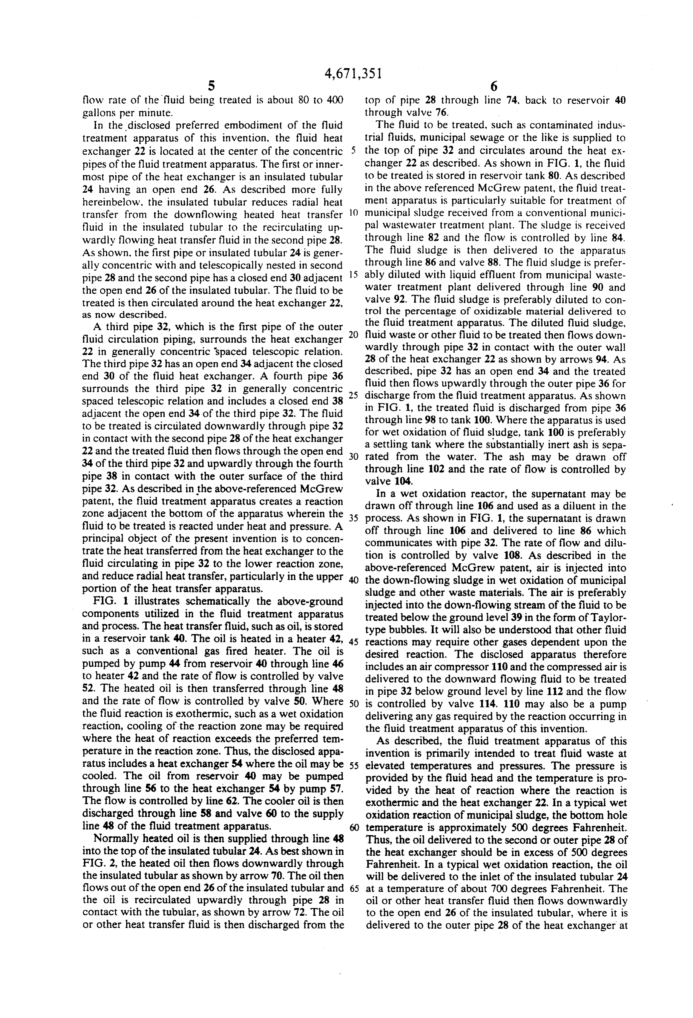
In the disclosed preferred embodiment of the fluid The fluid to be treated, such as contaminated indus treatment apparatus of this invention, the fluid heat trial fluids, municipal sewage or the like is supplied to exchanger 22 is located at the center of the concentric the top of pipe 32 and circulates around the heat ex pipes of the fluid treatment apparatus. The first or inner changer 22 as described. As shown in FIG. 1, the fluid most pipe of the heat exchanger is an insulated tubular to be treated is stored in reservoir tank 80. As described 24 having an open end 26. As described more fully in the above referenced McGrew patent, the fluid treat hereinbelow, the insulated tubular reduces radial heat ment apparatus is particularly suitable for treatment of transfer from the downflowing heated heat transfer 10 municipal sludge received from a conventional munici fluid in the insulated tubular to the recirculating up pal wastewater treatment plant. The sludge is received wardly flowing heat transfer fluid in the second pipe 28. through line 82 and the flow is controlled by line 84. As shown, the first pipe or insulated tubular 24 is gener The fluid sludge is then delivered to the apparatus ally concentric with and telescopically nested in second 15 through line 86 and valve 88. The fluid sludge is prefer pipe 28 and the second pipe has a closed end 30 adjacent ably diluted with liquid effluent from municipal waste the open end 26 of the insulated tubular. The fluid to be water treatment plant delivered through line 90 and treated is then circulated around the heat exchanger 22, valve 92. The fluid sludge is preferably diluted to con as now described. trol the percentage of oxidizable material delivered to A third pipe 32, which is the first pipe of the outer the fluid treatment apparatus. The diluted fluid sludge, fluid circulation piping, surrounds the heat exchanger 20 fluid waste or other fluid to be treated then flows down 22 in generally concentric spaced telescopic relation. wardly through pipe 32 in contact with the outer wall The third pipe 32 has an open end 34 adjacent the closed described,heat 28 of the exchanger 22 as shown by arrows 94. As pipe 32 has an open end 34 and the treated end 30 of the fluid heat exchanger. A fourth pipe 36 fluid then flows upwardly through the outer pipe 36 for surrounds the third pipe 32 in generally concentric spaced telescopic relation and includes a closed end 38 25 discharge from the fluid treatment apparatus. As shown adjacent the open end 34 of the third pipe 32. The fluid inthrough
FIG. 1, the treated fluid is discharged from pipe 36 line 98 to tank 100. Where the apparatus is used to be treated is circulated downwardly through pipe 32 in contact with the second pipe 28 of the heat exchanger for wet oxidation of fluid sludge, tank 100 is preferably 22 and the treated fluid then flows through the open end 30 arated settling tank where the substantially inert ash is sepa 34 of the third pipe 32 and upwardly through the fourth throughfrom line the water. The ash may be drawn off 102 and the rate of flow is controlled by pipe 38 in contact with the outer surface of the third valve 104.
pipe 32. As described in the above-referenced McGrew In a wet oxidation reactor, the supernatant may be patent, the fluid treatment apparatus creates a reaction drawn zone adjacent the bottom of the apparatus wherein the 35 process.offAsthrough line 106 and used as a diluent in the shown in FIG. 1, the supernatant is drawn fluid to be treated is reacted under heat and pressure. A off through line 106 and delivered to line 86 which principal object of the present invention is to concen trate the heat transferred from the heat exchanger to the communicates with pipe 32. The rate of flow and dilu tion is controlled by valve 108. As described in the fluid circulating in pipe 32 to the lower reaction zone, above-referenced McGrew patent, air is injected into and reduce radial heat transfer, particularly in the upper the down-flowing sludge in wet oxidation of municipal portion of the heat transfer apparatus.
FIG. 1 illustrates schematically the above-ground sludge and other waste materials. The air is preferably injected into the down-flowing stream of the fluid to be components utilized in the fluid treatment apparatus treated below the ground level 39 in the form of Taylor and process. The heat transfer fluid, such as oil, is stored type bubbles. It will also be understood that other fluid in a reservoir tank 40. The oil is heated in a heater 42, 45 reactions may require other gases dependent upon the such as a conventional gas fired heater. The oil is desired reaction. The disclosed apparatus therefore pumped by pump 44 from reservoir 40 through line 46 includes an air compressor 110 and the compressed air is to heater 42 and the rate of flow is controlled by valve delivered to the downward flowing fluid to be treated 52. The heated oil is then transferred through line 48 in pipe 32 below ground level by line 112 and the flow and the rate of flow is controlled by valve 50. Where 50 is controlled by valve 114. 110 may also be a pump the fluid reaction is exothermic, such as a wet oxidation delivering any gas required by the reaction occurring in reaction, cooling of the reaction zone may be required the fluid treatment apparatus of this invention. where the heat of reaction exceeds the preferred tem As described, the fluid treatment apparatus of this perature in the reaction zone. Thus, the disclosed appa invention is primarily intended to treat fluid waste at ratus includes a heat exchanger 54 where the oil may be 55 elevated temperatures and pressures. The pressure is cooled. The oil from reservoir 40 may be pumped provided by the fluid head and the temperature is pro through line 56 to the heat exchanger 54 by pump 57. vided by the heat of reaction where the reaction is The flow is controlled by line 62. The cooler oil is then exothermic and the heat exchanger 22. In a typical wet discharged through line 58 and valve 60 to the supply oxidation reaction of municipal sludge, the bottom hole line 48 of the fluid treatment apparatus. temperature is approximately 500 degrees Fahrenheit. Normally heated oil is then supplied through line 48 Thus, the oil delivered to the second or outer pipe 28 of into the top of the insulated tubular 24. As best shown in the heat exchanger should be in excess of 500 degrees FIG. 2, the heated oil then flows downwardly through Fahrenheit. In a typical wet oxidation reaction, the oil the insulated tubular as shown by arrow 70. The oil then will be delivered to the inlet of the insulated tubular 24 flows out of the open end 26 of the insulated tubular and 65 at a temperature of about 700 degrees Fahrenheit. The the oil is recirculated upwardly through pipe 28 in oil or other heat transfer fluid then flows downwardly contact with the tubular, as shown by arrow 72. The oil to the open end 26 of the insulated tubular, where it is or other heat transfer fluid is then discharged from the delivered to the outer pipe 28 of the heat exchanger at
Page 6
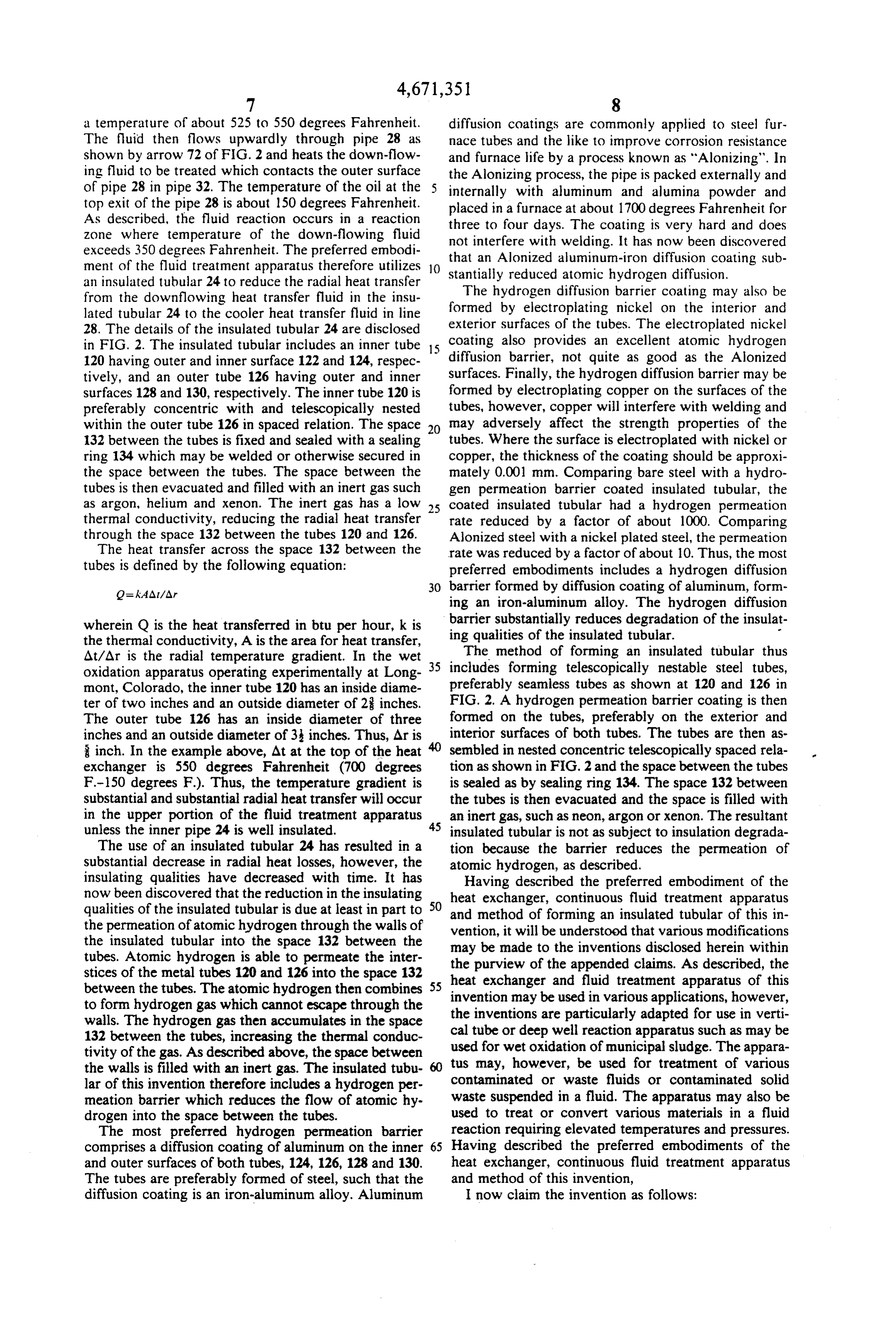
a temperature of about 525 to 550 degrees Fahrenheit. diffusion coatings are commonly applied to steel fur The fluid then flows upwardly through pipe 28 as nace tubes and the like to improve corrosion resistance shown by arrow 72 of FIG. 2 and heats the down-flow and furnace life by a process known as "Alonizing". In ing fluid to be treated which contacts the outer surface the Alonizing process, the pipe is packed externally and of pipe 28 in pipe 32. The temperature of the oil at the internally with aluminum and alumina powder and top exit of the pipe 28 is about 150 degrees Fahrenheit. placed in a furnace at about 1700 degrees Fahrenheit for As described, the fluid reaction occurs in a reaction three to four days. The coating is very hard and does zone where temperature of the down-flowing fluid exceeds 350 degrees Fahrenheit. The preferred embodi not that interfere with welding. It has now been discovered an Alonized aluminum-iron diffusion coating sub ment of the fluid treatment apparatus therefore utilizes O stantially reduced atomic hydrogen diffusion. an insulated tubular 24 to reduce the radial heat transfer
The hydrogen from the downflowing heat transfer fluid in the insu formed by electroplating diffusion barrier coating may also be lated tubular 24 to the cooler heat transfer fluid in line nickel on the interior and 28. The details of the insulated tubular 24 are disclosed exterior surfaces of the tubes. The electroplated nickel in FIG. 2. The insulated tubular includes an inner tube 15 coating also provides an excellent atomic hydrogen 120 having outer and inner surface 122 and 124, respec diffusion barrier, not quite as good as the Alonized tively, and an outer tube 126 having outer and inner surfaces. Finally, the hydrogen diffusion barrier may be surfaces 128 and 130, respectively. The inner tube 120 is formed by electroplating copper on the surfaces of the preferably concentric with and telescopically nested tubes, however, copper will interfere with welding and within the outer tube 126 in spaced relation. The space 20 may adversely affect the strength properties of the 132 between the tubes is fixed and sealed with a sealing tubes. Where the surface is electroplated with nickel or ring 134 which may be welded or otherwise secured in copper, the thickness of the coating should be approxi the space between the tubes. The space between the mately 0.001 mm. Comparing bare steel with a hydro tubes is then evacuated and filled with an inert gas such gen permeation barrier coated insulated tubular, the as argon, helium and xenon. The inert gas has a low 25 coated insulated tubular had a hydrogen permeation thermal conductivity, reducing the radial heat transfer rate reduced by a factor of about 1000. Comparing through the space 132 between the tubes 120 and 126. Alonized steel with a nickel plated steel, the permeation The heat transfer across the space 132 between the rate was reduced by a factor of about 10. Thus, the most tubes is defined by the following equation: preferred embodiments includes a hydrogen diffusion 30 barrier formed by diffusion coating of aluminum, form ing an iron-aluminum alloy. The hydrogen diffusion barrier wherein Q is the heat transferred in btu per hour, k is ing qualities substantially reduces degradation of the insulat the thermal conductivity, A is the area for heat transfer, of the insulated tubular. - At/Ar is the radial temperature gradient. In the wet 35 The method of forming an insulated tubular thus oxidation apparatus operating experimentally at Long includes forming telescopically nestable steel tubes, mont, Colorado, the inner tube 120 has an inside diame preferably seamless tubes as shown at 120 and 126 in ter of two inches and an outside diameter of 2 inches. FIG. 2. A hydrogen permeation barrier coating is then The outer tube 126 has an inside diameter of three formed on the tubes, preferably on the exterior and inches and an outside diameter of 3 inches. Thus, Aris interior surfaces of both tubes. The tubes are then as inch. In the example above, At at the top of the heat sembled in nested concentric telescopically spaced rela exchanger is 550 degrees Fahrenheit (700 degrees tion as shown in FIG.2 and the space between the tubes F-150 degrees F.). Thus, the temperature gradient is is sealed as by sealing ring 134. The space 132 between substantial and substantial radial heat transfer will occur the tubes is then evacuated and the space is filled with in the upper portion of the fluid treatment apparatus 45 an inert gas, such as neon, argon or xenon. The resultant unless the inner pipe 24 is well insulated. insulated tubular is not as subject to insulation degrada The use of an insulated tubular 24 has resulted in a tion because the barrier reduces the permeation of substantial decrease in radial heat losses, however, the atomic hydrogen, as described.
insulating qualities have decreased with time. It has Having described the preferred embodiment of the now been discovered that the reduction in the insulating heat exchanger, continuous fluid treatment apparatus qualities of the insulated tubular is due at least in part to 50 the permeation of atomic hydrogen through the walls of and method of forming an insulated tubular of this in vention, it will be understood that various modifications the insulated tubular into the space 132 between the may be made to the inventions disclosed herein within tubes. Atomic hydrogen is able to permeate the inter the purview of the appended claims. As described, the stices of the metal tubes 120 and 126 into the space 132 heat exchanger and fluid treatment apparatus of this between the tubes. The atomic hydrogen then combines 55 invention may be used in various applications, however, to form hydrogen gas which cannot escape through the the inventions walls. The hydrogen gas then accumulates in the space cal tube or deeparewell particularly adapted for use in verti reaction apparatus such as may be 132 between the tubes, increasing the thermal conduc tivity of the gas. As described above, the space between used for wet oxidation of municipal sludge. The appara the walls is filled with an inert gas. The insulated tubu tus may, however, be used for treatment of various contaminated or waste fluids or contaminated solid lar of this invention therefore includes a hydrogen per meation barrier which reduces the flow of atomic hy waste suspended in a fluid. The apparatus may also be drogen into the space between the tubes. used to treat or convert various materials in a fluid The most preferred hydrogen permeation barrier reaction requiring elevated temperatures and pressures. comprises a diffusion coating of aluminum on the inner 65 Having described the preferred embodiments of the and outer surfaces of both tubes, 124, 126, 128 and 130. heat exchanger, continuous fluid treatment apparatus The tubes are preferably formed of steel, such that the and method of this invention, diffusion coating is an iron-aluminum alloy. Aluminum I now claim the invention as follows:
Page 7
1. An elongated heat exchanger, comprising an elon nested within said first pipe in spaced relation having an gated insulated tubular having an open end generally open end adjacent said closed end of said first pipe, said concentric with telescopically nested in and surrounded insulated tubular comprising generally concentric tele by a second pipe having a closed end adjacent said open scopically nested spaced metal tubes, the space between end of said insulated tubular and communicating there 5 said tubes sealed and filled with an inert gas, a hot heat with, said insulated tubular having a first inner metal transfer fluid flowing through said insulated tubular in tube and a second outer metal tube generally concentric one direction, cooling and returning through said first with and surrounding said first tube in spaced relation, pipe in the opposite direction around said insulated the space between said first and second tubes sealed and tubular, and said circulation pipes comprising a second filled with an inert gas, a hot heat transfer fluid received 10 pipe telescopically surrounding said first pipe in spaced in one end of said insulated tubular and flowing through relation receiving the fluid to be treated in contact with said insulated tubular, said heat transfer fluid cooling said first pipe, and a third pipe generally concentric and returning through said second pipe for heating and with and surrounding said second pipe in spaced rela recirculation, and a hydrogen permeation barrier on the tion recirculating the treated fluid, the heat from said inner and outer surfaces of said first and second tubes of 15 heat transfer fluid thereby heating said fluid to be said insulated tubular, said hydrogen permeation barrier treated, and said insulated tubular having a hydrogen comprising a metal coating selected from the group permeation barrier, said hydrogen permeation barrier consisting of aluminum, nickel and copper, said perme comprising a coating means on the exterior and interior ation barrier reducing the flow of atomic hydrogen into surfaces of said nested metal tubes limiting permeation said space between said first and second tubes of said 20 of atomic hydrogen into said space between said tubes insulated tubular, thereby reducing heat losses from said and hydrogen gas build-up in said space, said barrier heat transfer fluid in said insulated tubular to the return reducing heat losses from the hot heat transfer fluid in ing heat transfer fluid in said second pipe. said insulated tubular to the returning heat transfer fluid 2. The heat exchanger defined in claim 1, character in said first pipe and providing a predetermined heating ized in that said first and second tubes of said insulated 25 Zone for the fluid being treated in said second pipe tubular are steel and said hydrogen diffusion barrier adjacent said closed end of said first pipe. consists of a diffusion coating of aluminum on said inner 5. The continuous fluid treatment apparatus defined and outer surfaces, forming an iron-aluminum alloy. in claim 4, characterized in that said tubes of said insu 3. The heat exchanger defined in claim i, character lated tubular are steel and said hydrogen diffusion bar ized in that said hydrogen diffusion barrier comprises an 30 rier consists of a diffusion coating of aluminum on said electroplated coating selected from the group consist inner and outer surfaces, forming an iron-aluminum ing of nickel and copper. alloy limiting diffusion of atomic hydrogen through said 4. A continuous fluid treatment apparatus for treat tubes.
ment of fluids at elevated temperatures, said fluid treat 6. The continuous fluid treatment apparatus defined ment apparatus including an elongated fluid heat ex 35 in claim 4, characterized in that said hydrogen diffusion changer surrounded by fluid circulation pipes contain barrier comprises an electroplated coating on said sur ing the fluid to fbe treated, said heat exchanger compris faces selected from the group consisting of nickel and ing a first pipe having a closed end and an insulated copper.
tubular generally concentric with and telescopically k it air xk k
Provenance
- Collection
- Cited prior art
- Original PDF
- patentimages.storage.googleapis.com →
- Filed
- 1985-07-17
- Pages
- 7
- Method
- pdftotext (the PDF's own text layer) + pdftoppm 300dpi page scans
- Source
- Google Patents bibliographic record
- Granted
- 1987-06-09
- Inventors
- Gerald C. Rappe; Vertech Treatment Systems Inc
- Transcribed from
- patentimages.storage.googleapis.com →