patent · US4535736
Method and apparatus for controlling air-fuel ratio in internal combustion engine
20 August 1985
Page 1 — bibliographic record
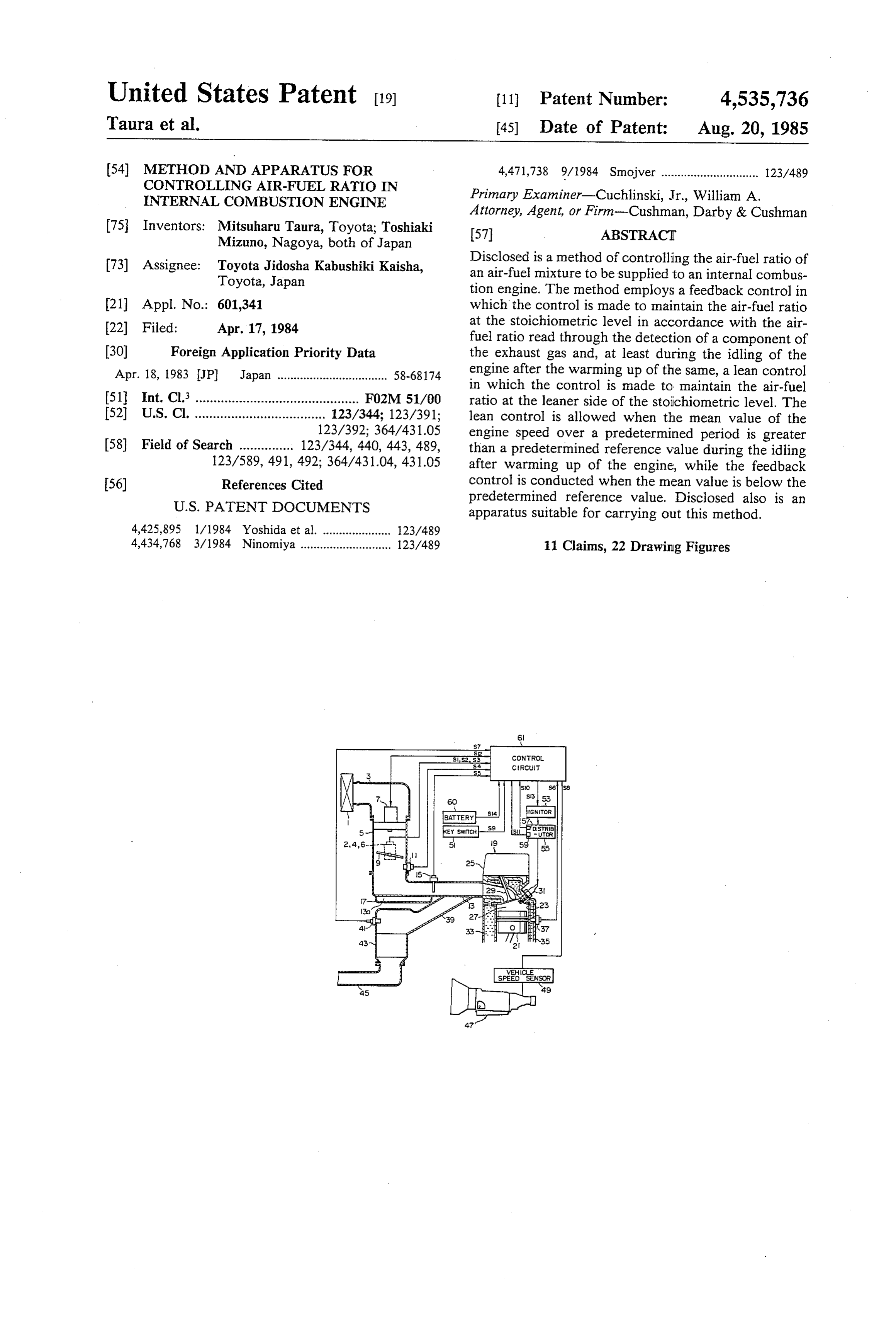
United States Patent (19) 11 Patent Number: 4,535,736 Taura et al. 45 Date of Patent: Aug. 20, 1985 (54) METHOD AND APPARATUS FOR 4,471,738 9/1984 Smojver .............................. 123/489
CONTROLLING AR-FUEL RATION
INTERNAL COMBUSTION ENGINE Primary Examiner-Cuchlinski, Jr., William A. Attorney, Agent, or Firm-Cushman, Darby & Cushman 75 Inventors: Mitsuharu Taura, Toyota; Toshiaki 57 ABSTRACT Mizuno, Nagoya, both of Japan 73) Assignee: Toyota Jidosha Kabushiki Kaisha, Disclosed is a method of controlling the air-fuel ratio of Toyota, Japan an air-fuel mixture to be supplied to an internal combus tion engine. The method employs a feedback control in 21 Appl. No.: 601,341 which the control is made to maintain the air-fuel ratio 22 Filed: Apr. 17, 1984 at the stoichiometric level in accordance with the air fuel ratio read through the detection of a component of (30) Foreign Application Priority Data the exhaust gas and, at least during the idling of the Apr. 18, 1983 JP Japan .................................. 58-68174 engine after the warming up of the same, a lean control in which the control is made to maintain the air-fuel 51 Int. Cl. ............................................. F02M 51/00 ratio at the leaner side of the stoichiometric level. The 52 U.S. Cl. .................................... 123/344; 123/391; lean control is allowed when the mean value of the 123/392; 364/431.05 engine speed over a predetermined period is greater 58 Field of Search ............... 123/344, 440, 443, 489, than a predetermined reference value during the idling 123/589, 491, 492; 364/431.04, 431.05 after warming up of the engine, while the feedback 56) References Cited control is conducted when the mean value is below the
apparatus suitable for carrying out this method.
4,425,895 1/1984 Yoshida et al. ..................... 123/489 4,434,768 3/1984 Ninomiya ............................ 123/489 11 Claims, 22 Drawing Figures
Page 2
Drawing sheet — no readable text.
Page 3
Drawing sheet — no readable text.
Page 4
START
READING OF
Pl ENGINE SPEED Ne
AND INTAKE PRESSURE PM
COMPUTATION OF BASIC
P2 NJECTION TIME DURATION TP
FROME PM AND Ne
P3 DETERMINATION OF CORRECTED
NJECTION TIME DURATION
THROUGH CORRECTING
COMPUTATION
DETERMINATION OF FINAL
P4 NJECTION TIME DURATION FX
BY VOLTAGE CORRECTION
COMPUTATION
P6 EXECUTION OF
NJECTION BY F 2
RETURN
Page 5
Drawing sheet — no readable text.
Page 6
COMPUTATION OF FWL COMPUTATION
COMPUTATION OF LEARNING
PCORRECTION AMOUNT TAG READING OF WATER
AND LEARNING CONTROL TEMPERATURE THW
CORRECTION COEFFICIENT KG P3 AND ENGINE SPEED
COMPUTATION OF WARM-UP
P2 NCREMENTAL
COEFFICIENT FWL P32 DETERMINATON
OF FW Lisb FROM
COMPUTATION
F3 OF FEED-BACK CORRECTION
COEFFICENT FAF P33 DETERMINATION
OF KWL FROM
Ne - KW MAP
P4 COMPUTATION
OF AIR-FUEL RATO
IN TRANSENT PERIOD P34 FWL-FWLPx KWL+O
CORRECTION COEFFICIENT FLEAN
F6 FTHA - THA + k
x F W L x FAF x FTHA x (FTC + FLEAN )
RETURN
Page 7
Drawing sheet — no readable text.
Page 8
Drawing sheet — no readable text.
Page 9
AIR-FUE RATIO
SIGNAL S7
AIR-FUEL RATIO
CORRECTION
COEFFICIENT
FAF
FIG. I.4
Out
S (s 3O 2OO 25 7O
AMOUT OF CHANGE OF S. 5 ENGINE COOLING
INTAKE PRESSURE (mm Hg) WATER TEMPERATURE
Page 10
FTC COMPUTATION
DETERMINATION OF AFTC.2s
P52 FROM DPM-AFTCS2 MAP
PERIOD ELAPSED
P56 Sec
WATER TEMPERATURE THW
DETERMINATION
9- OF KTc FROM THw-kTc MAP
RETURN
Page 11
Drawing sheet — no readable text.
Page 12
Drawing sheet — no readable text.
Page 13
Drawing sheet — no readable text.
Page 14
Drawing sheet — no readable text.
Page 15
Drawing sheet — no readable text.
Page 16
the engine without being accompanied by troubles such
METHOD AND APPARATUS FOR CONTROLLING as unstable engine operation or engine stall. AIR-FUEL RATION INTERNAL COMBUSTION To this end, according to the invention, in an internal ENGINE combustion engine wherein the air-fuel ratio of an air
BACKGROUND OF THE INVENTION
fuel mixture to be supplied to an internal combustion engine is controlled by selective use of a feedback con
The present invention relates to a method of and trol in which the control is made to maintain the air-fuel apparatus for controlling the air-fuel ratio of an air-fuel ratio at the stoichiometric level in accordance with the mixture which is to be supplied to an internal combus O air-fuel ratio and a lean control in which the control is tion engine. More particularly, the invention is con made to maintain the air-fuel ratio at the leaner side of cerned with an air-fuel ratio controlling method and the stoichiometric level at least during the idling of the apparatus in which the mode of air-fuel ratio control is engine after the warming up of the same, the lean con switched selectively in accordance with the state of the trol is executed when the mean value of the engine engine operation between a feedback control mode in 15 speed over a predetermined period is greater than a which the air-fuel ratio is controlled in conformity with predetermined reference value during the idling after the stoichiometric one and a feed-forward control mode warming up of the engine and the feedback control is referred to as "lean control' in which the control is executed when the mean value is below the predeter made to maintain an air-fuel ratio greater than the stoi mined reference value.
chiometric value, i.e. to maintain a mixture leaner than 20 It is, therefore, possible to execute the lean control the stoichiometric one. during the idling after the warming up of the engine, Generally, in automotive engines equipped with an without being accompanied by troubles such as unstable exhaust gas scrubber of ternary catalyst type, it is neces engine operation and engine stall. In addition, the con sary to effect the air-fuel ratio control such that the trol mode is shifted to the feedback control to ensure a air-fuel ratio, which is directly related to the condition 25 sufficient engine out torque any time the load is applied of combustion in the engine, is always maintained to the engine.
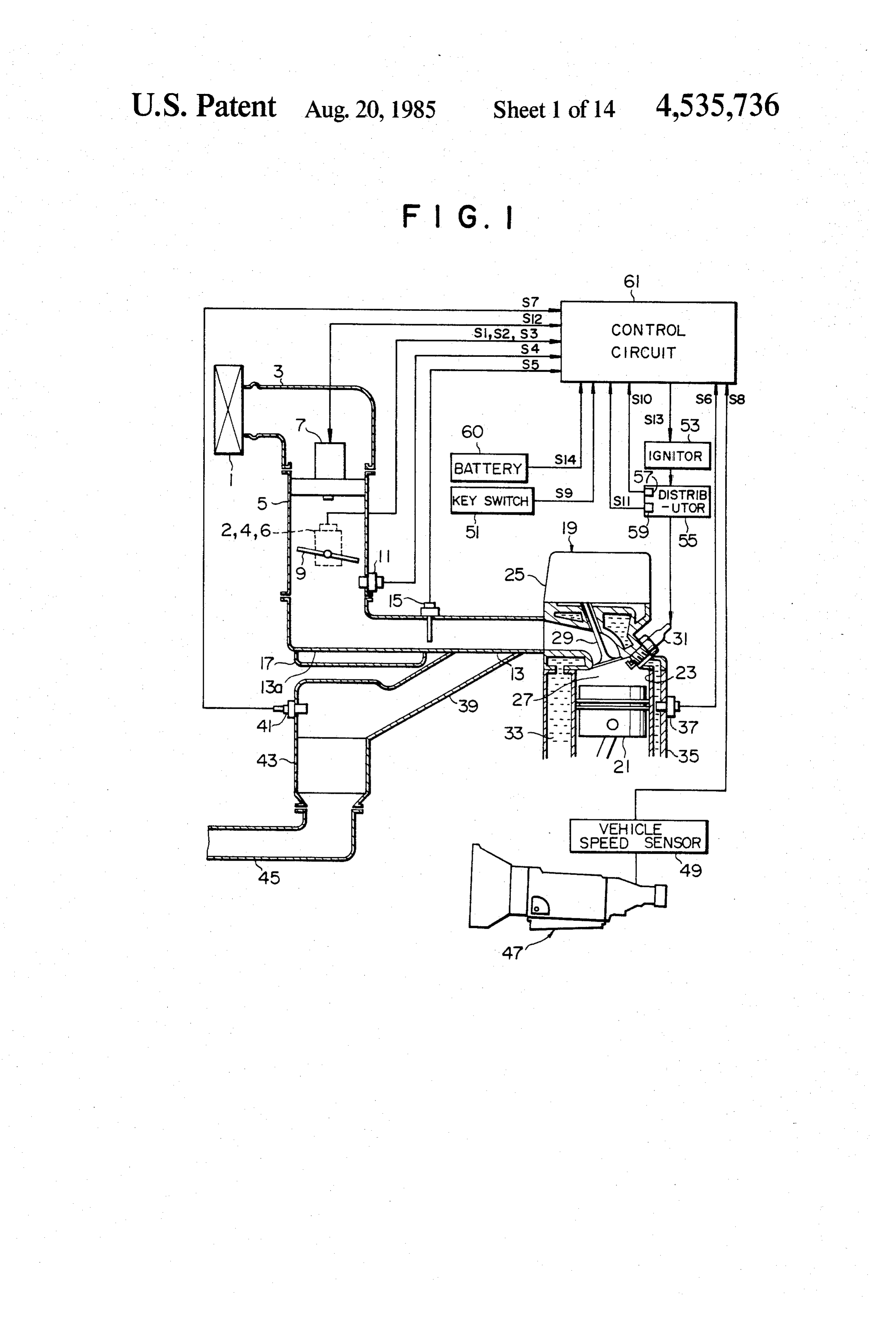
around the stoichiometric level, in order to keep the These and other objects, features and advantages of exhaust emissions clean. the invention will become clear from the following To cope with this demand, a feedback control description of the preferred embodiments taken in con method has been proposed and used in which the oxy 30 junction with the accompanying drawings. gen content in the exhaust gases is detected by an O2 BRIEF DESCRIPTION OF THE DRAWINGS sensor as an index of the air-fuel ratio of the mixture, and the air-fuel ratio control is conducted in accordance FIG. 1 is a schematic block diagram of an automotive with the output from the O2 sensor such that the air-fuel 35 internal combustion engine to which the present inven ratio coincides with the stoichiometric ratio. tion is applied;
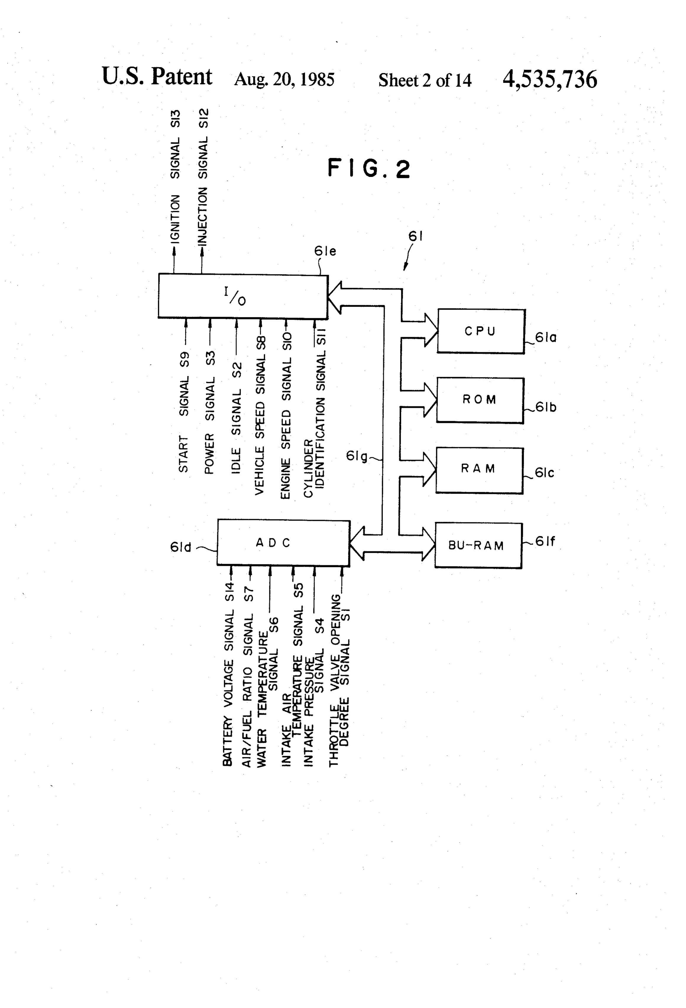
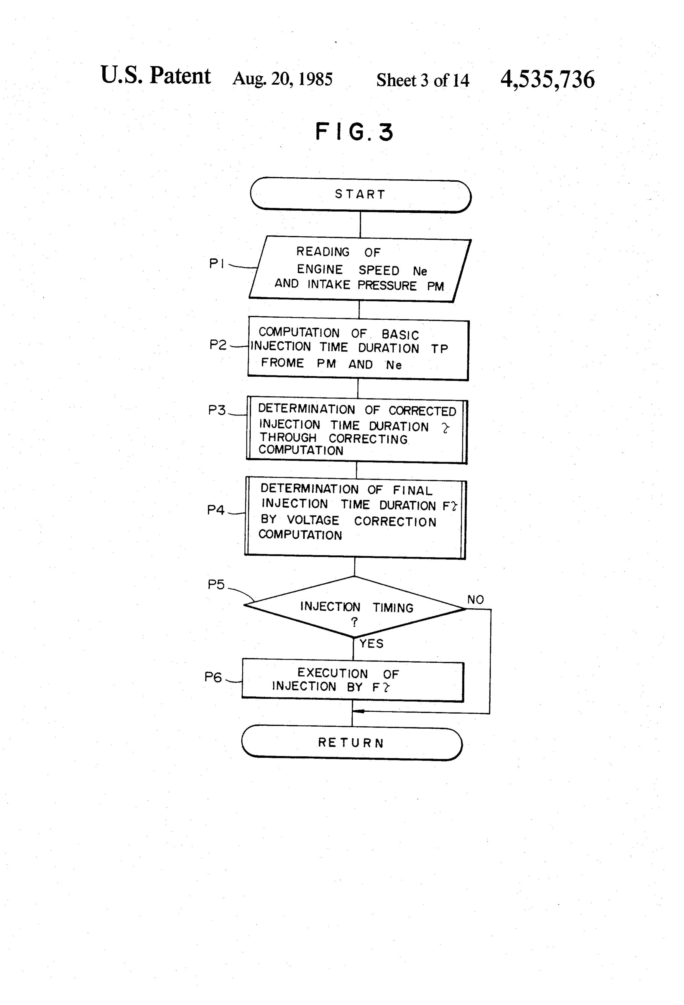
When the engine is operating under comparatively FIG. 2 is a detailed block diagram showing an exam light load, it is possible to decrease the rate of fuel con ple of the control circuit incorporated by the engine sumption by maintaining the air-fuel ratio at the leaner shown in FIG. 1;
side of the stoichiometric value without being accompa 40 FIG. 3 is a flow chart showing an example of fuel nied by substantial degradation of the exhaust emissions injection process;
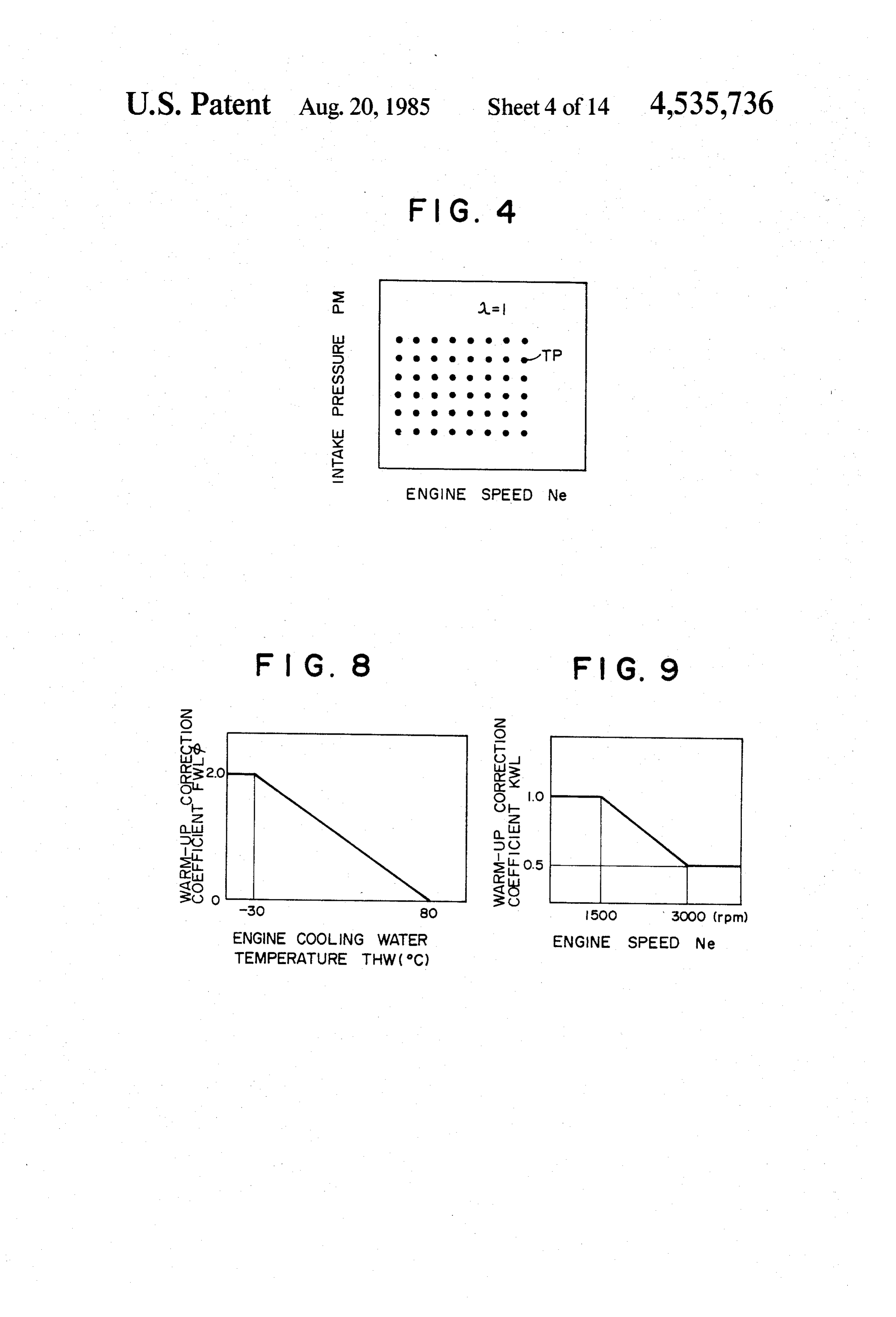
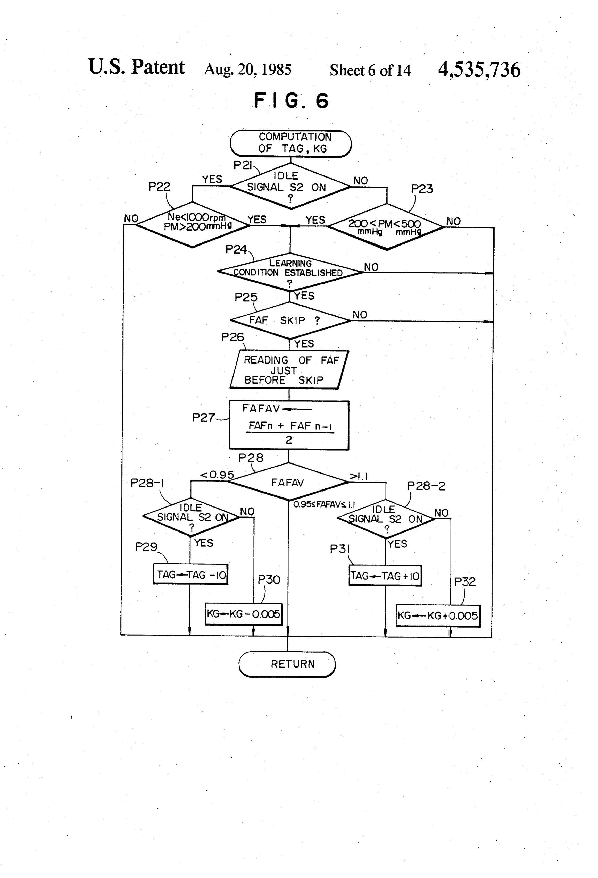
because, under the light load, the rate of generation of FIG. 4 is a diagram showing a map for determining nitrogen oxides is sufficiently small. Under these cir the basic fuel injection time duration TP with parame cumstances, an automotive engine has been proposed in ters of the engine speed Ne and the intake pressure PM; which the control operation mode is selectively 45 FIG. 5 is a flow chart showing an example of the switched between the feedback control mode for main process for determining corrected fuel injection time taining the air-fuel ratio at the stoichiometric level and duration T;
the lean control mode for maintaining the mixture at the FIG. 6 is a flow chart showing an example of the leaner side of the stoichiometric one through a feed-for process for computing learning correction amount ward control, thereby to minimize the fuel consump 50 TAG and learning control correction coefficient KG; tion. FIG. 7 is a flow chart showing an example of the The lean control, however, is an open loop control so process for computing the warm-up incremental coeffi that, if the lean control is conducted during idling in cient FWL;
which the combustion is unstable, the engine operation FIG. 8 is a graph showing the relationship between may become unstable and, in the worst case, the engine 55 the engine water temperature THW and warm-up cor may be stalled. rection coefficient FWLdb;
SUMMARY OF THE INVENTION FIG. 9 is a graph showing the relationship between the engine speed Ne and the warm-up correction coeffi
Accordingly, it is a first object of the invention to cient KWL;
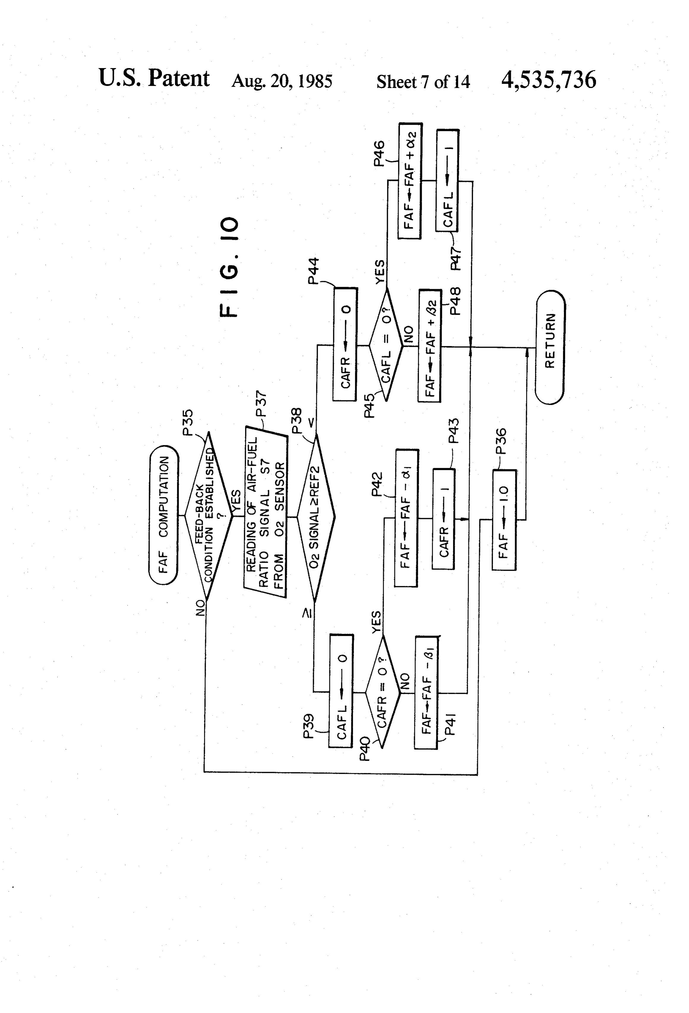
provide a method of controlling the air-fuel ratio of 60 FIG. 10 is a flow chart showing an example of the mixture to be fed to an internal combustion engine, process for computing the feedback correction coeffici improved to permit a lean control even during idling, ent FAF:
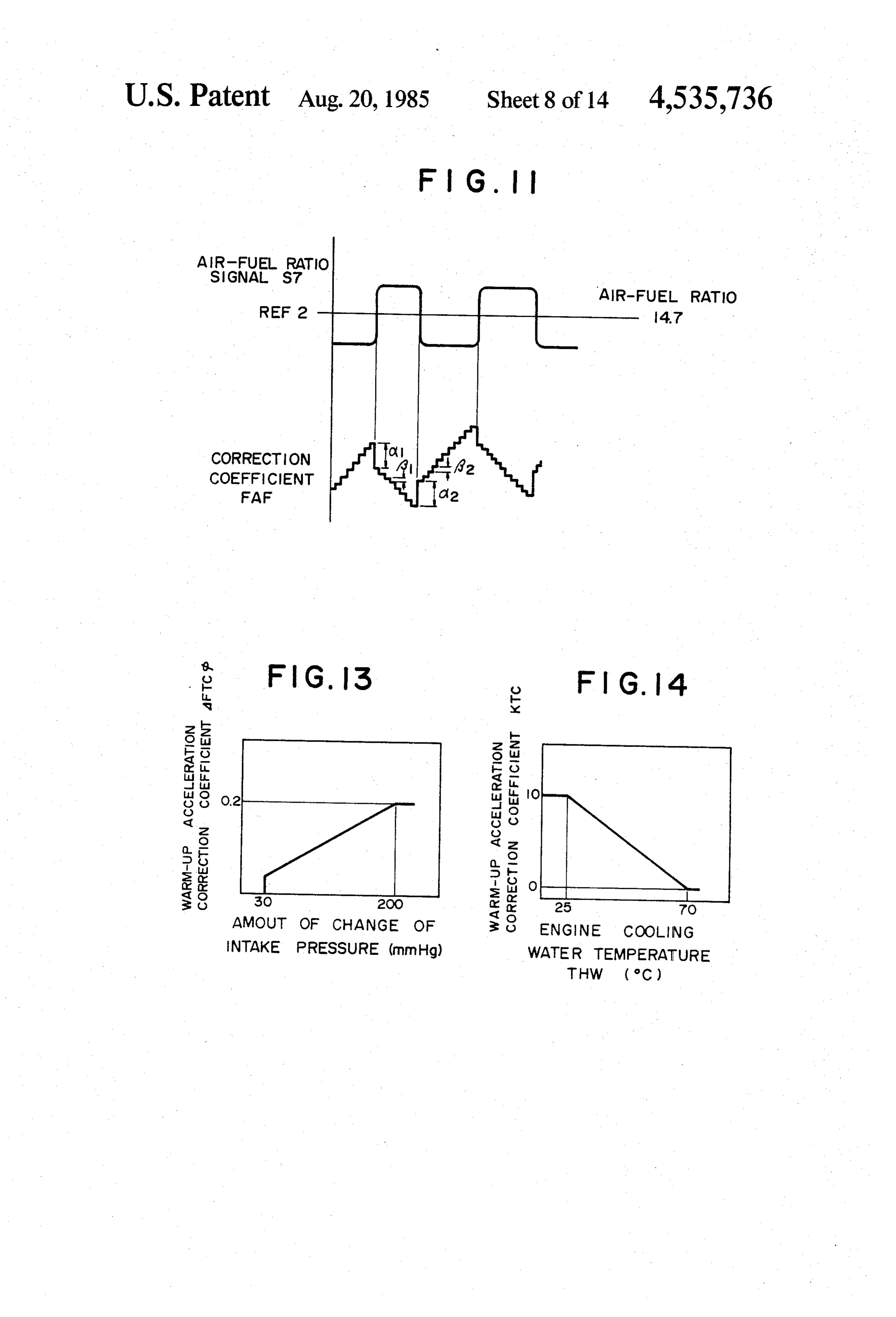
without being accompanied problems such as an unsta FIG. 11 is a time chart showing how the air-fuel ratio ble engine operation or engine stall. signal S7 and the correction coefficient FAF are It is a second object of the invention to provide an 65 changed in relation to time;
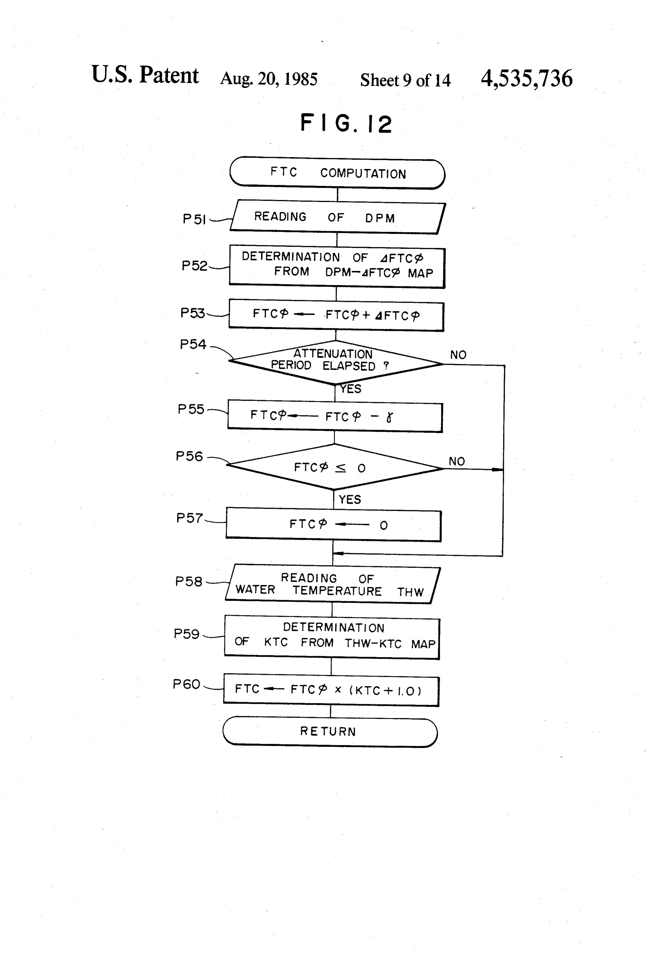
apparatus for controlling the air-fuel ratio of the mix FIG. 12 is a flow chart showing an example of the ture to be fed to an internal combustion engine, im process for computing the warm-up acceleration incre proved to permit a lean control even during idling of mental coefficient FTC;
Page 17
FIG. 13 is a graph showing the relationship between ated parts are cooled by cooling water which is circu the amount of change of the intake pressure DPM and lated through a water jacket 33 formed around the the correction coefficient AFTCdb; cylinder 23. The temperature of the cooling water in the FIG. 14 is a graph showing the relationship between water jacket 33 is sensed by a cooling water tempera the engine cooling water temperaturee THW and the ture sensor 37 attached to the outer wall of the clinder correction coefficient KTC; block 35.
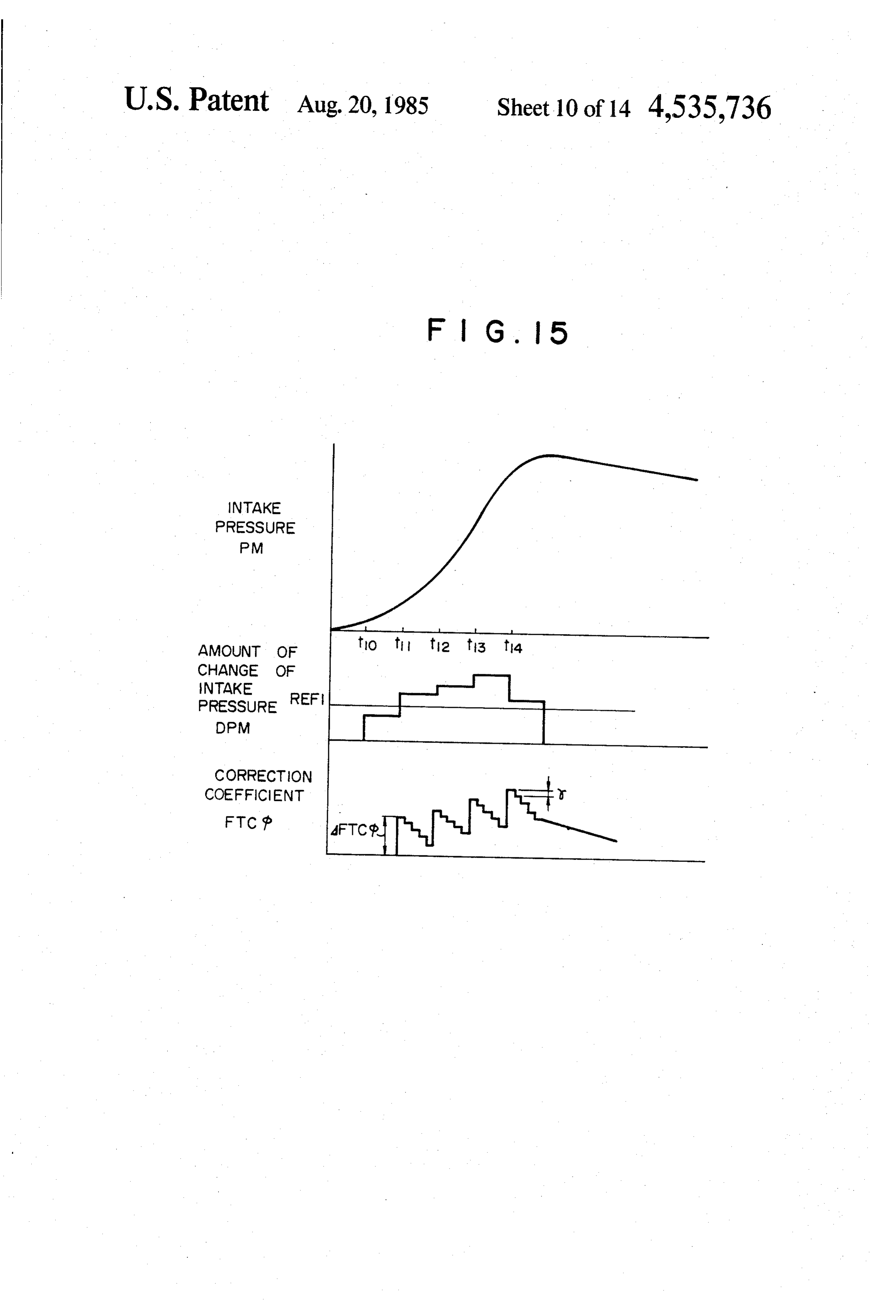
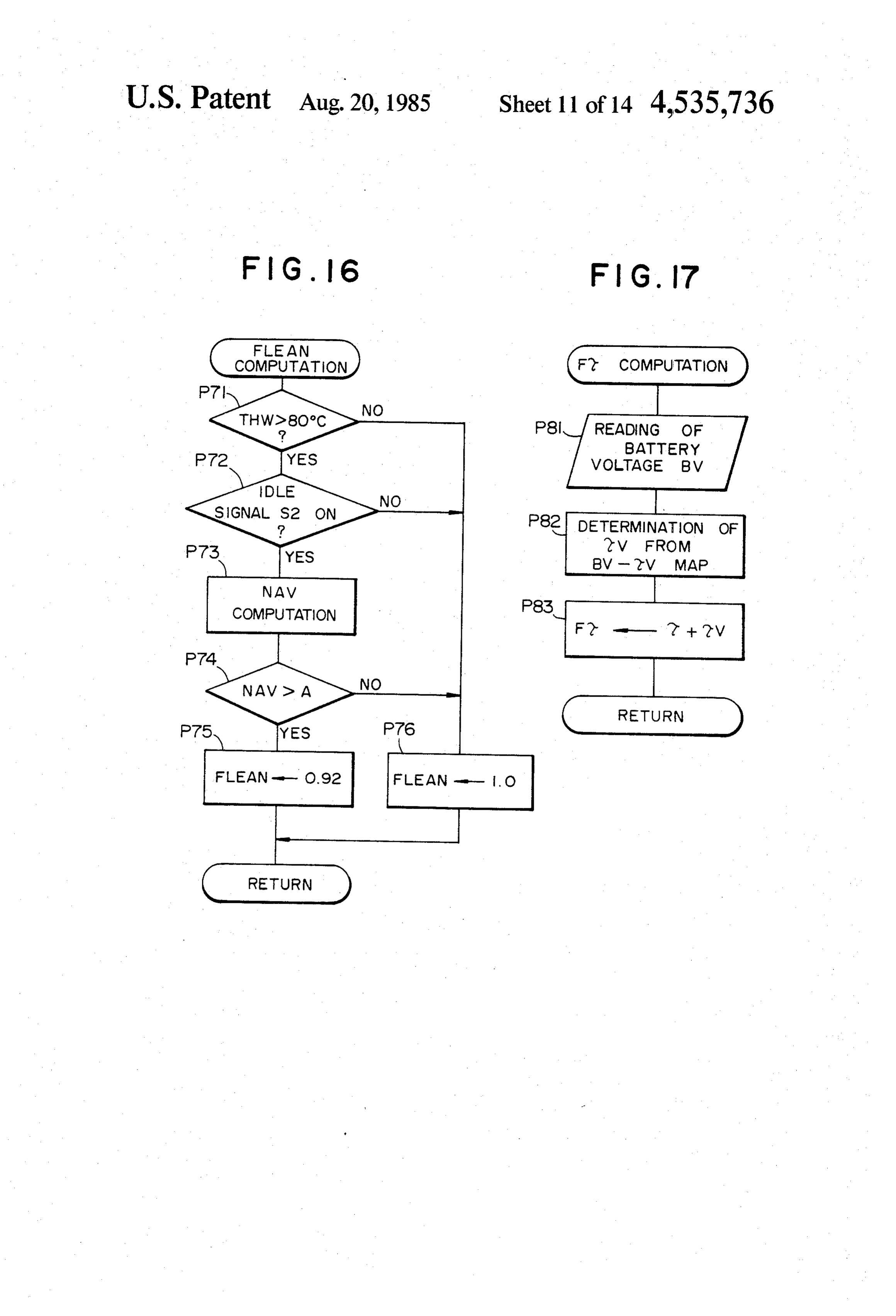
FIG. 15 is a time chart showing how the intake pres Branch pipes of an exhaust manifold 39 are connected sure PM, changing amount DPM of the same and the to the exhaust ports (not shown) formed in the cylinder correction coefficient FTCdb are changed in relation to heads 25 of respective cylinders 23. The exhaust mani time; 10 fold 39 is provided at its downstream end portion with FIG. 16 is a flow chart showing an example of the O2 sensor 41 adapted to sense the residual oxygen con process for computing the lean correction coefficient tent in the exhaust gas. The exhaust manifold 39 is con FLEAN nected to an exhaust pipe 45 through a ternary catalyst FIG. 17 is a flow chart showing an example of the 43.
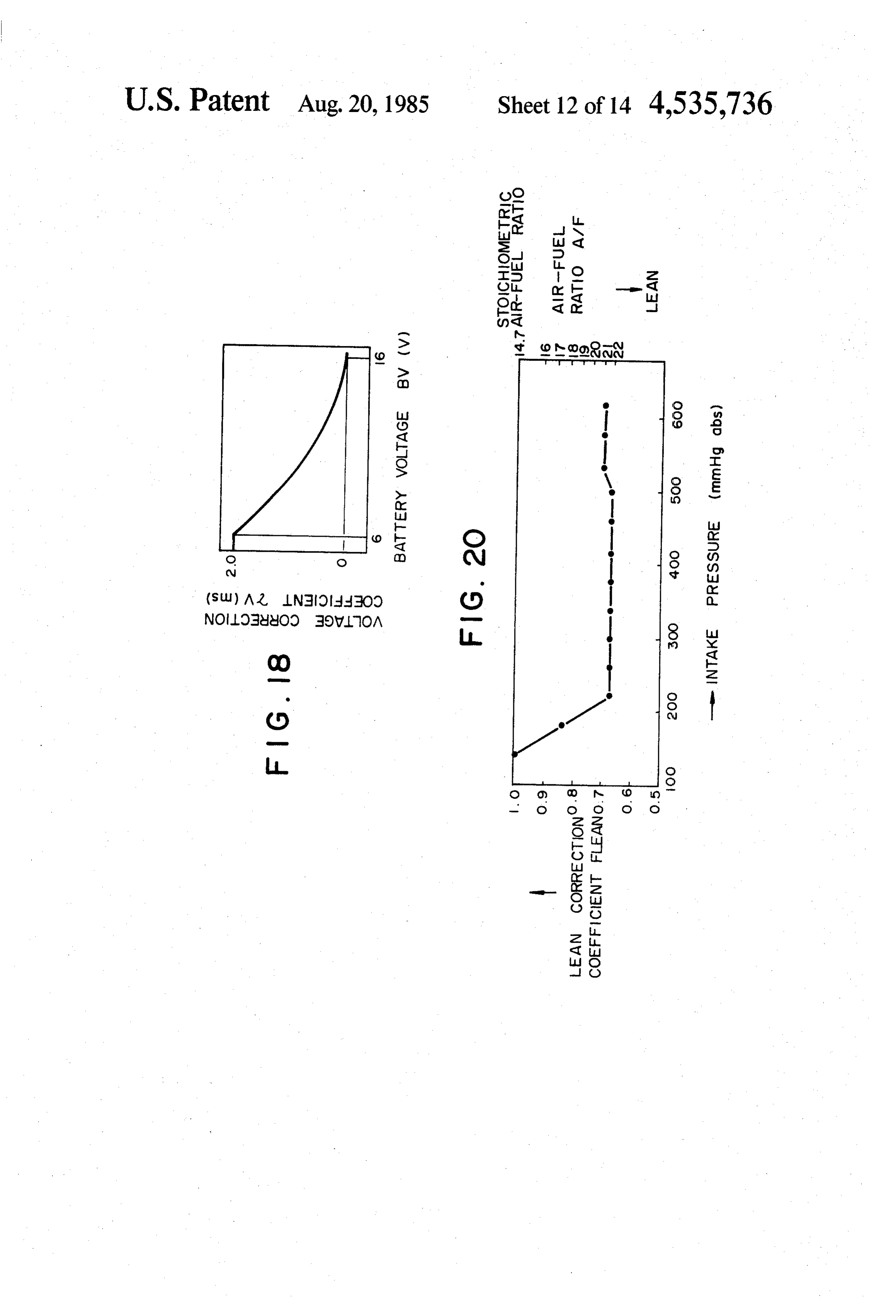
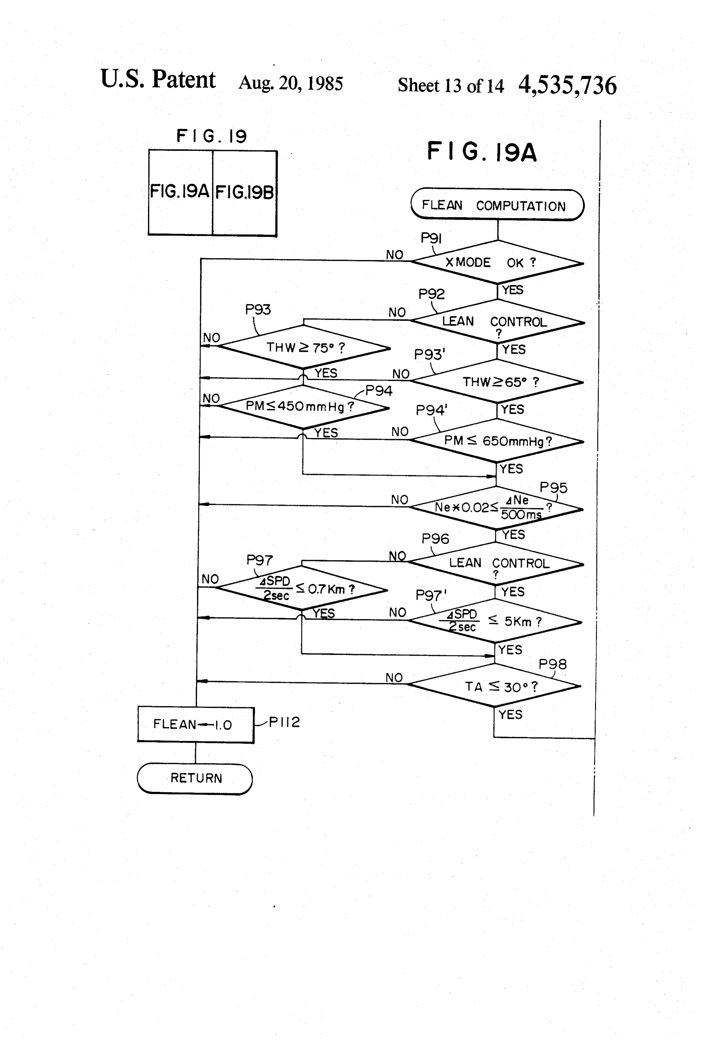
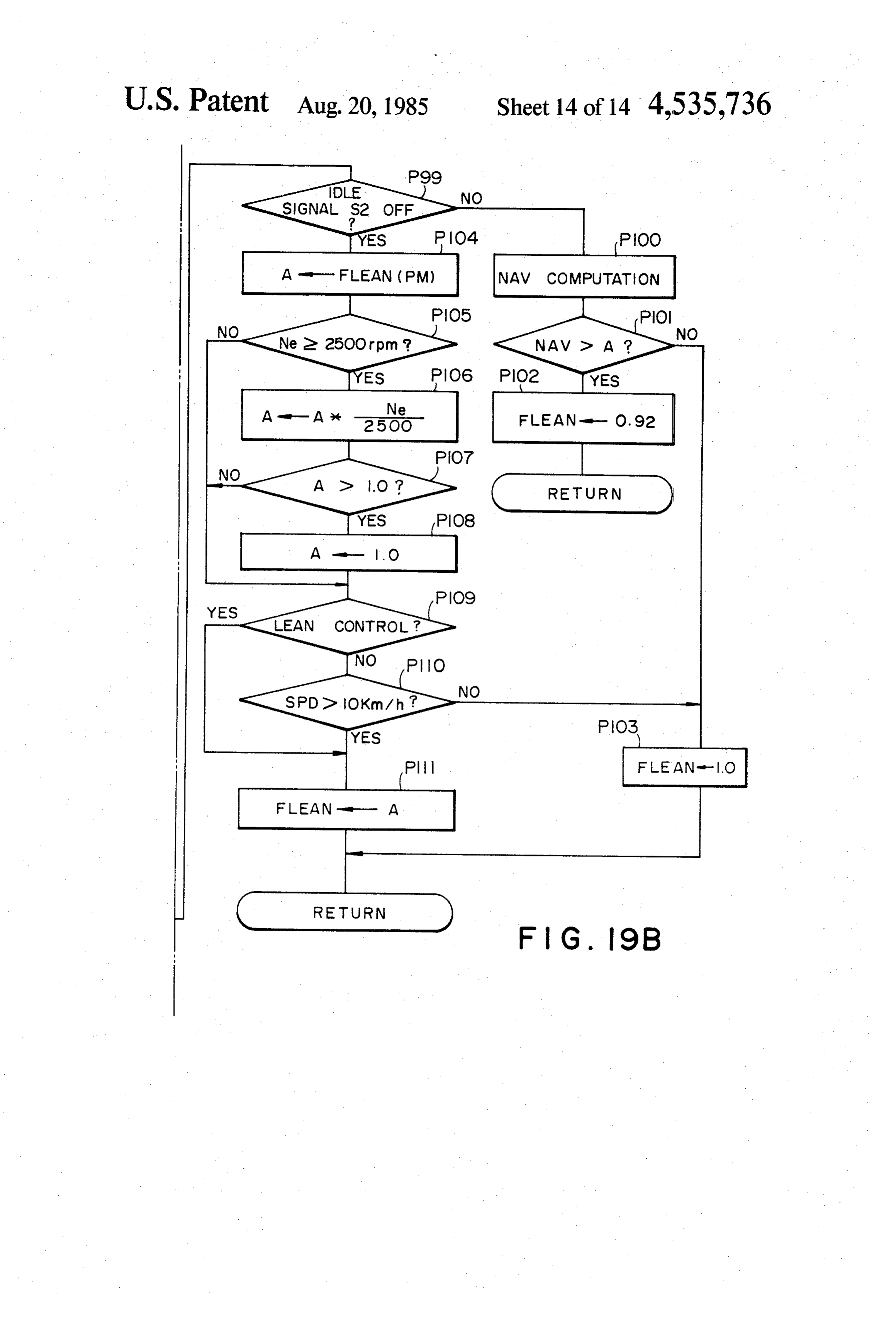
process for computing the final fuel injection time dura 15. The speed of the automobile is sensed by a vehicle tion Fr; . speed sensor 49 which is attached to the final output FIG. 18 is a graph showing the battery voltage BV shaft of a transmission 47 coupled to the body 19 of the and the voltage correction coefficient TV; engine. Reference numerals 51, 53 and 55 denote, re FIGS. 19, 19A and 19B are flow charts showing spectively, a key switch, igniter and a distributor. The another example of the process for computing the lean 20 distributor 55 is provided with an Ne sensor 57 adapted correction coefficient FLEAN; to produce an on-off signal for each angle 01 of the and crank rotation. It is possible to detect the engine speed FIG. 20 is a graph showing the relationship between and desired angular position of the crank from the out the correction coefficient FLEAN and the pressure put of the Ne sensor 57. A G sensor 59 which also is PM. 25 provided in the distributor 55 produces an on-off signal DESCRIPTION OF THE PREFERRED for each angle of 62 of crank rotation greater than the EMBODIMENTS above-mentioned angle 61. The discrimination or iden tification of the cylinders and detection of the top dead
FIG. 1 shows an example of an automotive internal centers are made by processing the output signal from combustion engine having an electronic fuel injection 30 the G sensor 59. A reference numeral 60 designates a system to which the invention is applied. An air filter 1 battery.
is connected to a throttle body 5 through an inlet pipe 3. A control circuit 61 is connected to various sensors The throttle body 5 is provided at its upstream side with such as the valve position sensor 2, idle switch 4, power a fuel injector 7. A throttle valve 9 disposed at the switch 6, intake pressure sensor 11, intake air tempera downstream side of the fuel injector 7 is operatively 35 ture sensor 15, cooling water temperature sensor 37, O2 connected to an accelerator pedal (not shown) so as to sensor 41, vehicle speed sensor 49, key switch 51, Ne control the intake air flow rate in accordance with the sensor 57, G sensor 59 and the battery 60. Thus, the position of the accelerator pedal (not shown). An abso control circuit 61 receives from these sensors various lute intake pressure sensor 11 disposed at the down signals such as a throttle valve opening degree signal stream side of the throttle valve 9 is adapted to sense the 40 S1, idle signal S2, power signal S3, intake pressure sig absolute pressure of the intake air at that portion. The nal S4, intake air temperature signal S5, water tempera throttle valve 9 is associated with various other parts ture signal S6, air-fuel ratio signal S7, vehicle speed such as a valve open position sensor 2 for measuring the signal S8, start signal S9, engine speed signal S10, cylin opening degree of the throttle valve 9, an idle switch 4 der identification signal S11 and the battery voltage which takes one position only when the throttle valve 9 45 signal S14.
is fully closed or substantially fully closed, and a power The control circuit 61 is connected also to the fuel switch 6 which is kept in on state when the opening injector 7 and the igniter 53 so that it can produce a fuel degree of the throttle valve 9 exceeds a predetermined injection signal S12 and a ignition signal S13. value such as, for example, 40. As shown in FIG. 2, the control circuit 61 has the The throttle body 5 is connected to an intake mani 50 following parts or constituents: a central processing unit fold 13 having branch pipes leading to respective cylin (CPU) 61a for controlling various devices; read only ders of the engine. The intake manifold 13 is provided memory (ROM) 61b in which written are various nu with an intake air temperature sensor 15 adapted to merical values and programs; a random access memory sense the temperature of the intake air in the intake (RAM) 61c having regions in which written are numeri manifold 13. The intake manifold 13 is provided on the 55 cal values obtained in the course of conputation, as well bottom wall 13a thereof at the upstream side of the as flags; an A/D converter (ADC) 61d for converting branching point with a riser portion 17 through which analog input signal into digital signals; an input/output the heated cooling water is circulated to heat the air interface (I/O) 61e through which various digital sig fuel mixture through the wall of the intake manifold. nals are inputted into and outputted from the control A reference numeral 19 designates the body of the 60 circuit; a backup memory (BU-RAM) 61f adapted to be engine known per se. The engine is provided with a supplied with electric power from an auxiliary power plurality of cylinders 23, pistons 21 and cylinder heads source when the engine is not operating thereby to hold 25 which in combination define combustion chambers the contents of the memory; and a BUS line 61g through 27 (only one of them is shown). Each cylinder is pro which these constituents are connected to one another. vided with an intake valve 29 through which the air 65 Programs which will be detailed later are written in the fuel mixture is introduced into the combustion chamber ROM 61b.
27. The mixture is then ignited by an ignition plug 31. In the operation of the engine described above, fuel is During the operation, the cylinder 23 and other associ injected in accordance with the flow chart shown in
Page 18
FIG. 3. More specifically, in a step P1, the engine speed On the other hand, if a negative answer is obtained in Ne is read in the form of the engine speed signal S1 the step P21, i.e. if it is confirmed that the throttle valve which is the reference position signal. At the same time, 9 is not fully closed, a judgement is made in a step P23 the intake pressure PM is read in the form of an intake as to whether the intake pressure is higher than, for pressure signal S4. In a step P2, the basic injection time example, 200 mmHg and below 500 mmHg. If the an duration TP is read from the map shown in FIG. 4 using swer is affirmative, the process proceeds to the step P24 the read values of the engine speed Ne and the intake to conduct the learning control.
pressure PM. In a step P3, a corrected injection time However, if the result of the judgement in the step duration T is determined through a computation which P22 or P23 indicates a negative answer, the learning is conducted in accordance with the operating condi 10 control is not conducted.
tion of the engine. In the step P24, a judgement is made as to whether A detailed description will be made hereinunder as to the conditions for the learning are met. For instance, the the process for computing the corrected injection time above learning amount TAG and learning control cor duration T in the step P3. rection coefficient KG are learned when the cooling The injection time duration it is generally obtainable 15 water temperature THW is above 80' and the intake air from the following formula. temperature THA falls between 40 and 90° C. while the engine is operating in the air-fuel ratio feedback
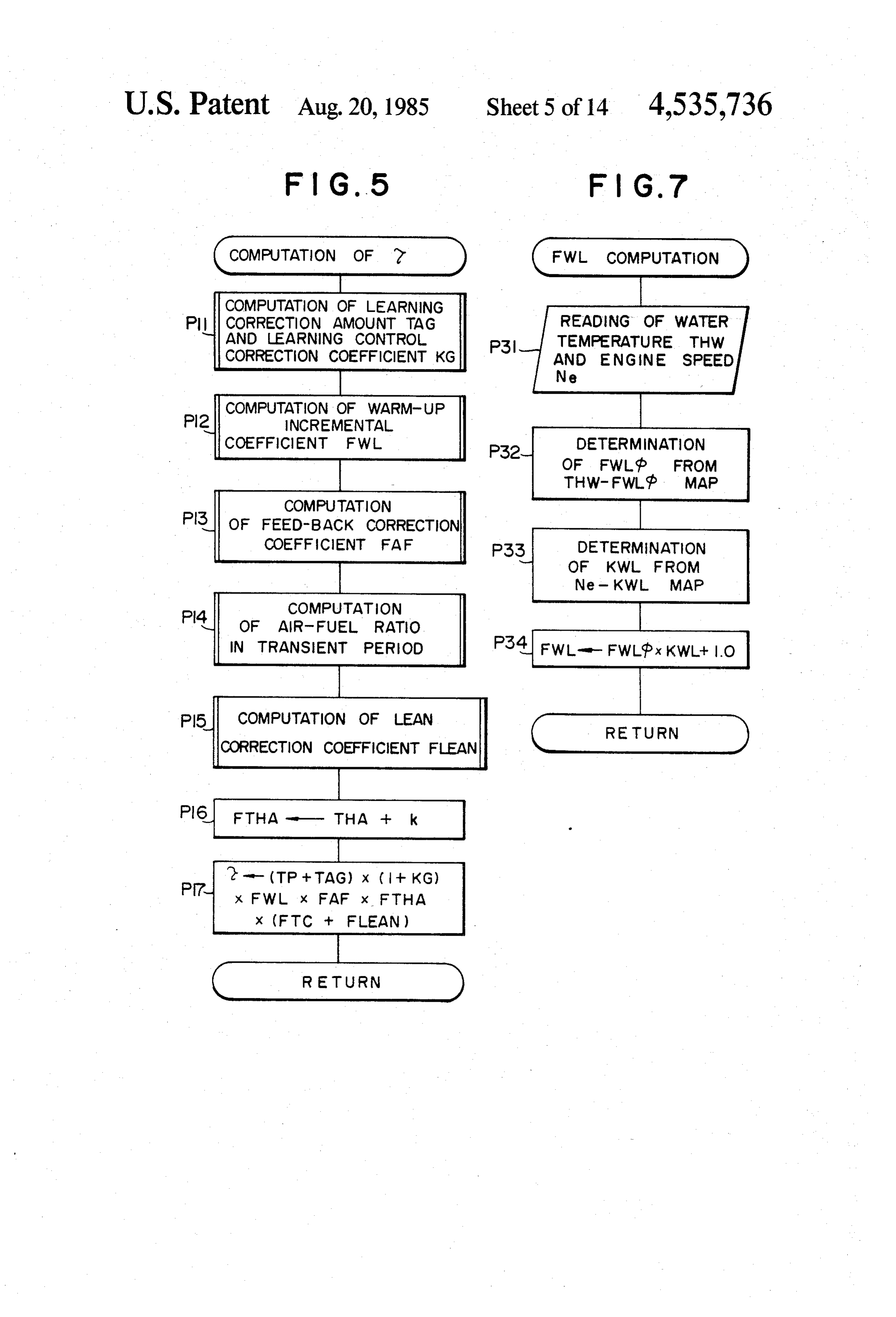
control mode. If it is judged that the conditions for the learning are met, a judgement is made in a step P25 as to 20 whether the feedback correction coefficient FAF has where, TP represents the basic fuel injection time dura been skipped or not. If the answer is affirmative, i.e. if tion, TAG represents the learning control amount, KG skipped, the process proceeds to a step P26. The judge represents the learning control correction coefficient, ment in the step P25 is made by detecting the change of FWL represents the warm-up incremental coefficient, states of the later-mentioned flags CAFL and CAFR FAF represents the air-fuel ratio feedback coefficient, 25 from “1” to "0". In the step P26, the correction coeffici FTC represents the transient-period air-fuel ratio cor ent FAF immediately before the skipping is read and rection coefficient, FTHA represents the intake air then, in a step P27, the arithmetic mean FAFAV of the temperature correction coefficient, and FLEAN repre presently read correction coefficient FAFn and the sents the lean correction coefficient. previously read correction coefficient FAF-1 is deter These coefficients are calculated in accordance with 30 mined and stored in a predetermined area. The level of the operation routine shown in FIG. 5 and the injection the arithmetic mean FAFAV is judged in the next step time duration t is determined using these coefficients. P28.
Namely, in a step P11, a calculation is made to deter If the value of the arithmetic mean FAFAV is smaller mine the learning control amount TAG and learning than 0.95, a judgement is made to whether the throttle control correction coefficient KG, while in a step P12, 35 valve 9 is fully closed or not in a step P28-1, If yes, the computation is made to determine the warm-up incre process proceeds to a step P29 in which 10 is subtracted mental coefficient FWL. In a step P13, a calculation is from the learning control amount TAG. The result of Inade to determine the air-fuel ratio feedback correction this subtraction is stored in the predetermined area as coefficient FAF. In the next step P14, a calculation is the new learning control amount TAG. If a judgement made to determine the air-fuel ratio correction coeffici is made in the step 28-1 that the throttle valve 9 is not ent FTC in the transient period. Subsequently, a calcu fully closed, the process proceeds to a step P30 in which lation is made to determine the lean correction coeffici 0.005 is subtracted from the learning control correction ent FLEAN in a step P15. Then, in a step P16, a calcula coefficient. The result of this subtraction is stored in the tion is made to determine the value of (THA--k), predetermined area as the new learning control correc thereby to determine the correction factor FTHA. Fi 45 tion coefficient KG.
nally, the computation is conducted in a step P17 in If the value of the arithmetic mean FAFAV is greater accordance with the formula (1) above, and the process than 1.1, a judgement is made as to whether the throttle is returned to the step P4 of the routine shown in FIG. valve 9 is fully closed or not in a step P28-2. If yes, the 3. process proceeds to a step P31 in which 10 is added to A description will be made hereinunder as to the 50 the learning control amount TAG. The result of this computing processes performed in the steps P11 to P15. addition is stored in the predetermined area as the new (1) Computation of Learning Control Amount TAG learning control amount TAG. If a judgement is made and Learning Control Correction Coefficient KG in the step 28-2 that the throttle valve 9 is not fully An example of the process for computing the learning closed, the process proceeds to a step P32 in which control amount TAG and the learning control correc 55 0.005 is added to the learning control correction coeffi tion coefficient KG will be explained hereinunder with cient. The result of this addition is stored in the prede reference to FIG. 6. termined area as the new learning control correction In a step P21, a judgement is made as to whether the coefficient KG.
throttle valve 9 has been closed fully or not, through In sum, the air-fuel ratio is learned by the learning discriminating whether the idle signal S2 from the idle 60 control amount TAG when the throttle valve is fully switch S4 is on or off. If an affirmative judgement is closed, whereas the air-fuel ratio is learned by the learn made, i.e. if the full closing of the throttle valve 9 is ing control correction coefficient KG when the throttle confirmed, a judgement is made in a step P22 as to valve is opened.
whether the engine speed Ne is less than, for example, The thus determined learning correction amount 1000 rpm and as to whether the intake pressure PM is 65 TAG is used in the correction of the basic fuel injection greater than, for example, 200 mmHg. If an affirmative time duration regardless of the opening degree of the result is obtained in this judgement, the process pro throttle valve, whereas the learning control correction ceeds to a step P24 for making the learning control. coefficient KG is used for the similar correction only
Page 19
within the learned region of engine operation where the is too large, i.e. the mixture is too lean, so that a process learning control correction coefficient KG is learned. is taken to decrease the air-fuel ratio, i.e. to make the (2) Computation of Warm-Up Incremental Coeffici mixture richer.
ent FWL More specifically, the process proceeds to a step P45 An example of the process for computing the warm 5 after setting the flag CAFR at zero in a step P44. In the up incremental coefficient FWL is shown in FIG. 7. step P45, a judgement is made as to whether state of the The cooling water temperature THW and the engine flag CAFL is zero or not. If the process has been shifted speed Ne are read in a step P31. In the next step P32, the to leaner side for the first time, th process proceeds to a correction coefficient FWLdb is determined on the basis step P46 because the state of the flag CAFL is zero. In of the thus read newest cooling water temperature O the step P46, a predetermined value a2 is added to the THW using a map which shows, as will be seen from correction coefficient FAF and the result of this addi FIG. 8, the relationship between the cooling water tion is used as the new FAF. In a step P47, the state of temperature THW and the correction coefficient the flag CAFL is set to be 1. Therefore, if the mixture is FWLdb. In the next step P33, the correction coefficient judged to be too lean in two successive judging cycles KWL is determined on the basis of the thus read newest 15 in the step P38, a negative judgement is made without engine speed Ne using a map which shows, as will be fail in the second and the following judging cycles in seen from FIG. 9, the relationship between the engine the step P45. Then, the process proceeds to a step P4.8 speed Ne and the correction coefficient KWL. Then, in in which a predetermined value (32 is added to the cor a step P34, the value (FWLdbXKWL)+1.0 is computed rection coefficient FAF and the result of this addition is thus completing this process. 20 used as the new FAF, thus completing the FAF opera (3) Computation of Feedback Correction Coefficient tion. The values a1, a2, 31 and 62 used in the steps P41, FAF P42, P46 and P4.8 are the values which have been deter An example of the process for computing the feed mined beforehand.
back correction coefficient FAF is shown in FIG. 10. The feedback correction coefficient FAF determined A judgement is made in a step P35 to judge whether 25 through this operation is shown in FIG. 11 together the condition for the feedback control has been estab with the air-fuel ratio signal S7. The following will be lished. The condition for the feedback control is estab noted from this Figure. Namely, when the signal S7 lished when all of the following requirements are met: rises above the reference value REF2 or drops below the engine is not being started nor in the power incre the same, the correction coefficient FAF is skipped by mental mode after start-up; the cooling temperature is an amount all or a2. Thereafter, when the signal S7 not lower than 40 C.; and the engine is not in the power exceeds the reference value, the predetermined value incremental mode nor in the lean control mode. If the g1 is subtracted successively, whereas, if the signal S7 is condition for the feedback control has not been estab below the reference value, the predetermined value g2 lished, the feedback correction coefficient FAF is set at is added successively.
1.0 in the step P36 to prohibit the feedback control 35 (4) Computation of Air-Fuel Ratio Correction Coeffi thereby to complete this process. On the other hand, if cient FTC in Transient Period the condition for the feedback control has been estab An example of the process for computing the air-fuel lished, the process proceeds to a step P37. ratio correction coefficient FTC in transient period is The air-fuel ratio signal S7 is read in the step P37. In shown in FIG. 12. In this example, only the correction a step P38, this air-fuel ratio signal S7 is compared with 40 coefficient FTC in the acceleration incremental mode a reference value REF2. When the level of the signal S7 during warming up of the engine is discussed. The exceeds the reference value REF2, it is judged that the changing amount DPM of the intake pressure PM has air-fuel ratio is too small, i.e. the mixture is too rich, and been calculated suitably, and is read suitably in a step the process is started to increase the air-fuel ratio, i.e. to P51. Then, in a step P52, the correction coefficient make the mixture more lean. 45 AFTCdb is determined in accordance with the changing Namely, after setting the flag CAFL at zero in a step amount DPM from a map which shows, as will be seen P39, the process proceeds to a step P40 in which a from FIG. 13, the relationship between the changing judgement is made as to whether or not the state of the amount DPM and the warm-up acceleration correction flag CAFR is zero. If the process has been shifted to coefficient AFTCdb due to the changing amount in the richer side for the first time, the state of the flag CAFR 50 intake pressure. In the next step P53, the correction is zero so that the process proceeds to a step P42 in coefficient AFTCdb thus determined in the step P52 is which a predetermined value a1 is subtracted from the added to the correction factor FTCdb which has been correction coefficient FAF stored in the RAM 61C and determined already, and the sum is used as the new the result of this calculation is used as new correction correction factor FTCdb. The step then proceeds to a coefficient FAF. 55 step P54 in which a judgement is made as to whether or In the step P43, the flag CAFR is set to be 1. There not a predetermined period of time necessary for attenu fore, if the air-fuel mixture is judged to be too rich in ating the thus obtained correction coefficient FTCdb by successive two judging cycles in the step P38, negative an amount y has been elapsed. If the result of the judge judgement is made without fail in the step P40 in the ment is affirmative, the process proceeds to a step P55. second and the following judging cycles, so that the In the step P55, a computation is made to determine the process proceeds to a step P41 in which a predeter value of (FTCdb-y) and the result of this computation is mined value (31 is subtracted from the correction coeffi stored in a predetermined area as a new correction cient FAF. The result of this calculation is then stored coefficient FTCdb. Then, in a step P56, a judgement is in a predetermined area as the new correction coeffici made as to whether the correction coefficient FTCdb is ent FAF, thus completing the computation of FAF. 65 smaller than zero. If the result of this judgement is affir On the other hand, if the judgement in the step P38 mative, the correction coefficient FTCdb is set to be proves the level of the signal S7 to be smaller than the zero in a step P57 and the procees proceeds to the next reference value REF2, it is judged that the air-fuel ratio step P58. If the negative answer is obtained through the
Page 20
judgement in the step P54 or the step P56, the process tion coefficient TV. In a step P83, computation of also jumps to the step P58. (t + TV) is conducted to determine the final injection In a step P58, the cooling water temperature THW is time duration Ft. The process then returns to the step read in the form of the water temperature signal S6. In P5 shown in FIG. 3. If the present instant coincides the next step P59, the correction coefficient KTC is with the injection timing, an injection signal S12 corre read on the basis of this cooling water temperature sponding to the final injection time duration FT is deliv THW from a map which shows, as will be seen from ered from the control circuit 61 to the injector 7, FIG. 14, the relationship between the cooling water thereby to drive the latter.
temperature THW and the warm-up acceleration cor The intake air temperature correction coefficient rection coefficient KTC. The process then proceeds to O FTHA, which is determined in the step P16 shown in a step P60 in which a computation of FIG. 5, is intended for the compensation for the vari FTCdbX(KTC+1.0) is made to determine the warm-up ance of the density of the intake air attributable to the acceleration correction coefficient FTC. change in the air temperature. The correction coefficient FTCdb obtained through As will be understood from the foregoing descrip the steps P51 to P55 is shown in FIG. 15 together with 15 tion, in the described embodiment of the invention, the the intake pressure PM and the changing amount DPM basic fuel injection time duration TP is multiplied by the of the same. As will be seen from this Figure, a prede lean correction coefficient FLEAN = 0.92 to maintain termined value AFTCdb is added to the correction coef the air-fuel ratio at the leaner side of the stoichiometric ficient FTCdb at each time the changing amount DPM level, only when the mean value NAV of the engine at every time points t10-t14 exceeds the reference value 20 speed within a predetermined period is higher than a REF 1. At the same time, in the time interval between predetermined reference value while the engine is idling the successive time points the attenuation value y is after the warming up of the same. Thus, even when the subtracted from the correction factor FTCdb at a prede engine is idling after the warming up, the lean correc termined period. tion coefficient FLEAN is set at 1.0 at any time the (5) Computation of Lean Correction Coefficient 25 mean value NAV of the engine speed falls below the FLEAN reference value, thereby to permit a feedback control In a step P71, a judgement is made as to whether or for maintaining the air-fuel ratio around the stoichio not the cooling water temperature THW is high enough metric level.
to complete the warm-up of the engine, i.e. whether or According to the invention, therefore, it is possible to not is is raised to 80 C., for example. If the answer is 30 avoid the troubles such as unstable engine operation or affirmative, the process proceeds to a step P72 in which the engine stall even if the lean control is conducted a judgement is made as to whether the throttle valve 9 during the idling after the warming up of the engine. In is fully closed, by using the idle signal S2 derived from the described embodiment, the learning control amount the idle switch 4. If the throttle valve 9 is fully closed, TAG for the learning control of the air-fuel ratio is a computation is made in the step P73 to determine the 35 computed when all of the following conditions are met: mean value NAV of the engine speed Ne within a pre namely, the throttle valve 9 is fully closed; the engine is determined period of time. Then, in a step P74, the under the feedback control; the engine speed Ne is mean value NAV is compared with a reference value A. below a predetermined speed; and the intake pressure If the mean value NAV is greater than the reference PM is higher than a predetermined pressure, and the value A, the lean correction coefficient FLEAN stored basic fuel injection time duration is corrected in accor in the predetermined area of the RAM 61C is set to be dance with at least the learning control amount TAG 0.92 in a step P75, thereby to permit the execution of the over the whole region of the engine operation. Also in lean control. To the contrary, if the mean value NAV is the described embodiment of the invention, even if the smaller than the reference value A, the lean correction lean control is executed in the idling of the engine after coefficient FLEAN is set to be 1.0, thereby to permit 45 the warming up, the lean control is not effected but the the execution of the feedback control. In case that the feedback control is conducted instead, provided that cooling water temperature THW is below 80° C. or the the mean value NAV of the engine speed is below a throttle valve 9 is not fully closed, negative answer is reference value. It is, therefore, possible to increase the made in the step P71 or P72, so that the correction chance of the learning of the above-mentioned learning coefficient FLEAN is set to be 1.0. In such a case, 50 correction amount TAG and, hence, to conduct the therefore, the lean control is not executed but the feed control of the air-fuel ratio delicately and precisely. back control becomes possible. An explanation will be made hereinunder as to an The corrected injection time duration it is determined other example of the process for computing the lean in the step 17 shown in FIG. 5 using various correction correction coefficient FLEAN. With specific reference coefficients which are determined in the manner ex 55 to FIG. 19, in this example, the lean control is carried plained hereinbefore. Then, the process jumps to the out in all operational conditions of the engine. step P4 in the flow chart shown in FIG. 3 in which a As a program as shown in FIG. 19 is started, a judge voltage correction computing process is conducted to ment is made in a step P91 as to whether the mode determine the final injection time duration Ft. condition XMODE is satisfied or not. More specifi The voltage correction computing process in the step 60 cally, this condition is satisfied when the engine is not P4 of the flow chart shown in FIG. 3 is executed by a being started up nor in the post-start fuel incremental voltage correction computing routine shown in FIG. phase nor in the power incremental mode. The judge 17. In a step P81, the battery voltage BV is read in terms ment as to whether or not the engine is not being started of a battery voltage signal S14. In the next step P82, up is made in accordance with the start signal S9 and using the thus read battery voltage BV, a voltage cor 65 the engine speed signal S10. The judgement concerning rection coefficient TV is determined on a map which the post-start fuel incremental mode after the starting is shows, as will be seen from FIG. 18, the relationship made on the basis of post-start fuel incremental coeffici between the battery voltage BV and the voltage correc ent FSE stored in a predetermined memory area. The
Page 21
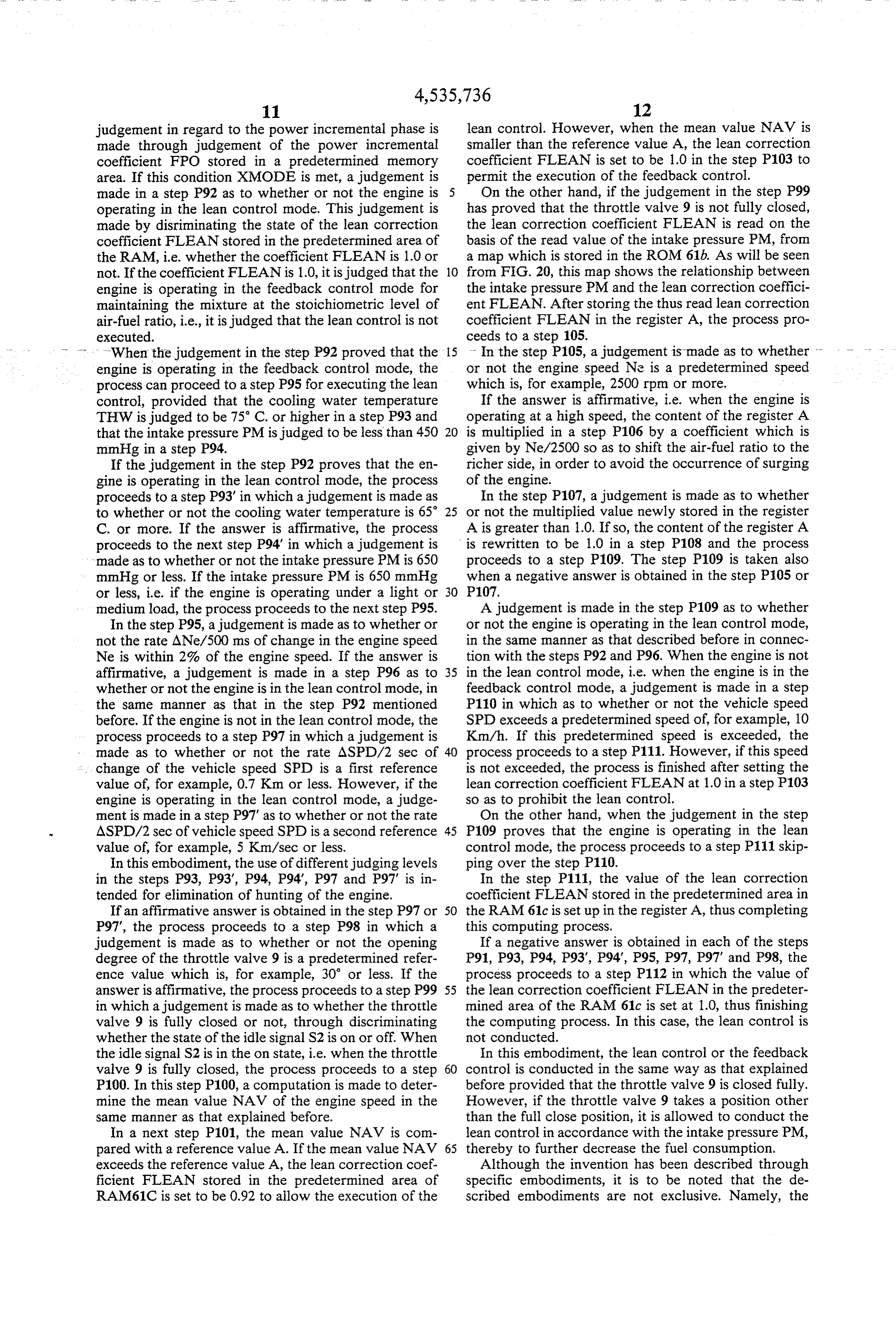
judgement in regard to the power incremental phase is lean control. However, when the mean value NAV is made through judgement of the power incremental smaller than the reference value A, the lean correction coefficient FPO stored in a predetermined memory coefficient FLEAN is set to be 1.0 in the step P103 to area. If this condition XMODE is met, a judgement is permit the execution of the feedback control. made in a step P92 as to whether or not the engine is On the other hand, if the judgement in the step P99 operating in the lean control mode. This judgement is has proved that the throttle valve 9 is not fully closed, made by disriminating the state of the lean correction the lean correction coefficient FLEAN is read on the coefficient FLEAN stored in the predetermined area of basis of the read value of the intake pressure PM, from the RAM, i.e. whether the coefficient FLEAN is 1.0 or a map which is stored in the ROM 61b. As will be seen not. If the coefficient FLEAN is 1.0, it is judged that the 10 from FIG. 20, this map shows the relationship between engine is operating in the feedback control mode for the intake pressure PM and the lean correction coeffici maintaining the mixture at the stoichiometric level of ent FLEAN. After storing the thus read lean correction air-fuel ratio, i.e., it is judged that the lean control is not coefficient FLEAN in the register A, the process pro executed. ceeds to a step 105.
When the judgement in the step P92 proved that the 15 - In the step P105, a judgement is made as to whether - engine is operating in the feedback control mode, the or not the engine speed Ne is a predetermined speed process can proceed to a step P95 for executing the lean which is, for example, 2500 rpm or more. control, provided that the cooling water temperature If the answer is affirmative, i.e. when the engine is THW is judged to be 75° C. or higher in a step P93 and operating at a high speed, the content of the register A that the intake pressure PM is judged to be less than 450 20 is multiplied in a step P106 by a coefficient which is mmHg in a step P94. given by Ne/2500 so as to shift the air-fuel ratio to the If the judgement in the step P92 proves that the en richer side, in order to avoid the occurrence of surging gine is operating in the lean control mode, the process of the engine.
proceeds to a step P93' in which a judgement is made as In the step P107, a judgement is made as to whether to whether or not the cooling water temperature is 65 25 or not the multiplied value newly stored in the register C. or more. If the answer is affirmative, the process A is greater than 1.0. If so, the content of the register A proceeds to the next step P94 in which a judgement is is rewritten to be 1.0 in a step P108 and the process made as to whether or not the intake pressure PM is 650 proceeds to a step P109. The step P109 is taken also mmHg or less. If the intake pressure PM is 650 mmHg when a negative answer is obtained in the step P105 or or less, i.e. if the engine is operating under a light or 30 P107.
medium load, the process proceeds to the next step P95. A judgement is made in the step P109 as to whether In the step P95, a judgement is made as to whether or or not the engine is operating in the lean control mode, not the rate ANe/500 ms of change in the engine speed in the same manner as that described before in connec Ne is within 2% of the engine speed. If the answer is tion with the steps P92 and P96. When the engine is not affirmative, a judgement is made in a step P96 as to 35 in the lean control mode, i.e. when the engine is in the whether or not the engine is in the lean control mode, in feedback control mode, a judgement is made in a step the same manner as that in the step P92 mentioned P110 in which as to whether or not the vehicle speed before. If the engine is not in the lean control mode, the SPD exceeds a predetermined speed of, for example, 10 process proceeds to a step P97 in which a judgement is Km/h. If this predetermined speed is exceeded, the made as to whether or not the rate ASPD/2 sec of 40 process proceeds to a step P111. However, if this speed : change of the vehicle speed SPD is a first reference is not exceeded, the process is finished after setting the value of, for example, 0.7 K.m or less. However, if the lean correction coefficient FLEAN at 1.0 in a step P103 engine is operating in the lean control mode, a judge so as to prohibit the lean control.
ment is made in a step P97' as to whether or not the rate On the other hand, when the judgement in the step ASPD/2 sec of vehicle speed SPD is a second reference 45 P109 proves that the engine is operating in the lean value of, for example, 5 Km/sec or less. control mode, the process proceeds to a step P111 skip In this embodiment, the use of different judging levels ping over the step P110.
in the steps P93, P93, P94, P94, P97 and P97' is in In the step P111, the value of the lean correction tended for elimination of hunting of the engine. coefficient FLEAN stored in the predetermined area in If an affirmative answer is obtained in the step P97 or 50 the RAM 61c is set up in the register A, thus completing P97", the process proceeds to a step P98 in which a this computing process.
judgement is made as to whether or not the opening If a negative answer is obtained in each of the steps degree of the throttle valve 9 is a predetermined refer P91, P93, P94, P93, P94, P95, P97, P97 and P98, the ence value which is, for example, 30 or less. If the process proceeds to a step P112 in which the value of answer is affirmative, the process proceeds to a step P99 55 the lean correction coefficient FLEAN in the predeter in which a judgement is made as to whether the throttle mined area of the RAM 61c is set at 1.0, thus finishing valve 9 is fully closed or not, through discriminating the computing process. In this case, the lean control is whether the state of the idle signal S2 is on or off. When not conducted.
the idle signal S2 is in the on state, i.e. when the throttle In this embodiment, the lean control or the feedback valve 9 is fully closed, the process proceeds to a step 60 control is conducted in the same way as that explained P100. In this step P100, a computation is made to deter before provided that the throttle valve 9 is closed fully. mine the mean value NAV of the engine speed in the However, if the throttle valve 9 takes a position other same manner as that explained before. than the full close position, it is allowed to conduct the In a next step P101, the mean value NAV is com lean control in accordance with the intake pressure PM, pared with a reference value A. If the mean value NAV 65 thereby to further decrease the fuel consumption. exceeds the reference value A, the lean correction coef. Although the invention has been described through ficient FLEAN stored in the predetermined area of specific embodiments, it is to be noted that the de RAM61C is set to be 0.92 to allow the execution of the scribed embodiments are not exclusive. Namely, the
Page 22
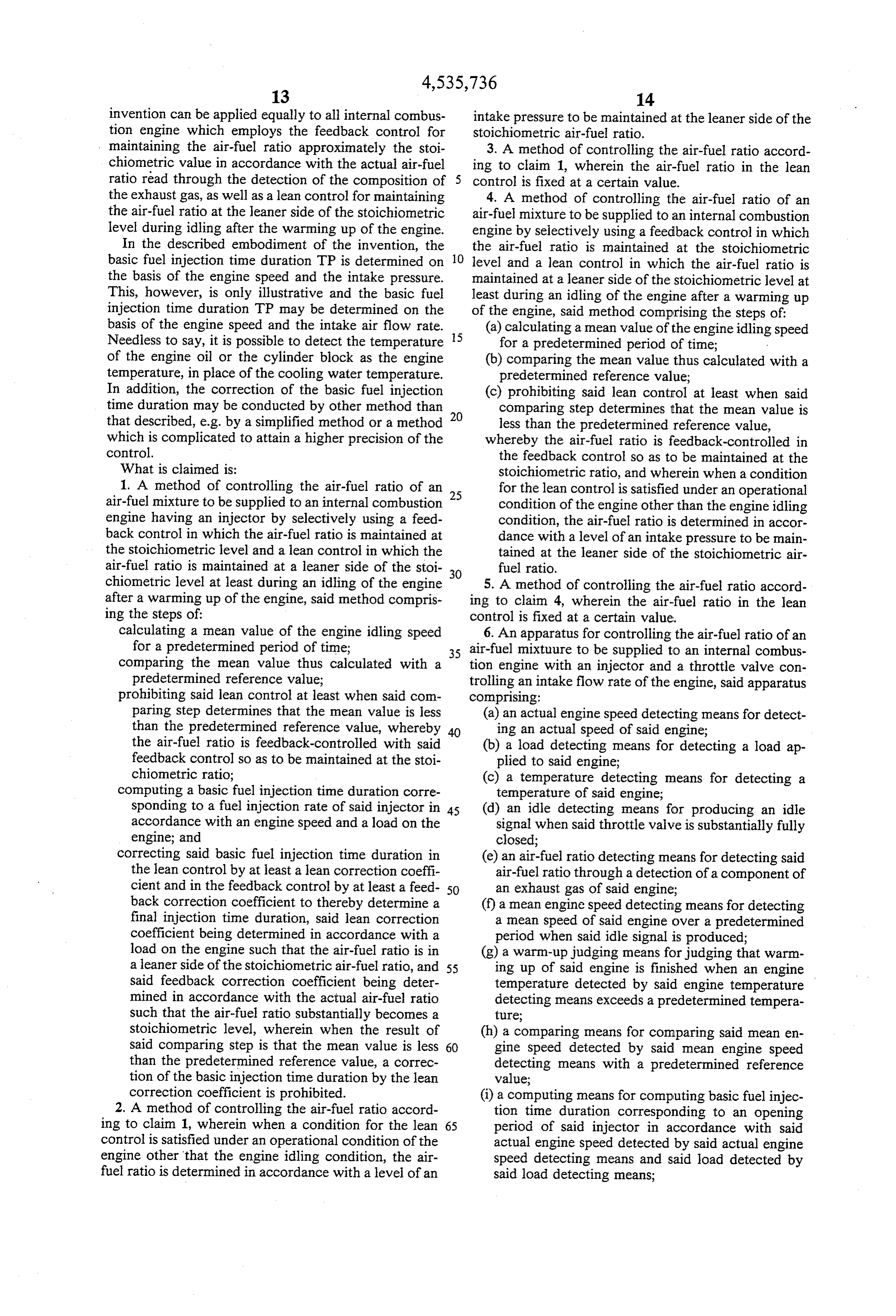
invention can be applied equally to all internal combus intake pressure to be maintained at the leaner side of the tion engine which employs the feedback control for stoichiometric air-fuel ratio. maintaining the air-fuel ratio approximately the stoi 3. A method of controlling the air-fuel ratio accord chiometric value in accordance with the actual air-fuel ing to claim 1, wherein the air-fuel ratio in the lean ratio read through the detection of the composition of 5 control is fixed at a certain value. the exhaust gas, as well as a lean control for maintaining 4. A method of controlling the air-fuel ratio of an the air-fuel ratio at the leaner side of the stoichiometric air-fuel mixture to be supplied to an internal combustion level during idling after the warming up of the engine. engine by selectively using a feedback control in which In the described embodiment of the invention, the the air-fuel ratio is maintained at the stoichiometric basic fuel injection time duration TP is determined on 10 level and a lean control in which the air-fuel ratio is the basis of the engine speed and the intake pressure. maintained at a leaner side of the stoichiometric level at This, however, is only illustrative and the basic fuel least during an idling of the engine after a warming up injection time duration TP may be determined on the of the engine, said method comprising the steps of: basis of the engine speed and the intake air flow rate. 15 (a) calculating a mean value of the engine idling speed Needless to say, it is possible to detect the temperature for a predetermined period of time; of the engine oil or the cylinder block as the engine (b) comparing the mean value thus calculated with a temperature, in place of the cooling water temperature. predetermined reference value;
In addition, the correction of the basic fuel injection (c) prohibiting said lean control at least when said time duration may be conducted by other method than comparing step determines that the mean value is that described, e.g. by a simplified method or a method 20 less than the predetermined reference value, which is complicated to attain a higher precision of the whereby the air-fuel ratio is feedback-controlled in control. the feedback control so as to be maintained at the What is claimed is: stoichiometric ratio, and wherein when a condition 1. A method of controlling the air-fuel ratio of an for the lean control is satisfied under an operational air-fuel mixture to be supplied to an internal combustion 25 condition of the engine other than the engine idling engine having an injector by selectively using a feed condition, the air-fuel ratio is determined in accor back control in which the air-fuel ratio is maintained at dance with a level of an intake pressure to be main the stoichiometric level and a lean control in which the tained at the leaner side of the stoichiometric air air-fuel ratio is maintained at a leaner side of the stoi fuel ratio.
chiometric level at least during an idling of the engine 30 5. A method of controlling the air-fuel ratio accord after a warming up of the engine, said method compris ing to claim 4, wherein the air-fuel ratio in the lean ing the steps of: control is fixed at a certain value. calculating a mean value of the engine idling speed 6. An apparatus for controlling the air-fuel ratio of an for a predetermined period of time; 35 air-fuel mixtuure to be supplied to an internal combus comparing the mean value thus calculated with a tion engine with an injector and a throttle valve con predetermined reference value; trolling an intake flow rate of the engine, said apparatus prohibiting said lean control at least when said com comprising:
paring step determines that the mean value is less (a) an actual engine speed detecting means for detect than the predetermined reference value, whereby 40 ing an actual speed of said engine; the air-fuel ratio is feedback-controlled with said (b) a load detecting means for detecting a load ap feedback control so as to be maintained at the stoi plied to said engine;
chiometric ratio; (c) a temperature detecting means for detecting a computing a basic fuel injection time duration corre temperature of said engine; sponding to a fuel injection rate of said injector in 45 (d) an idle detecting means for producing an idle accordance with an engine speed and a load on the signal when said throttle valve is substantially fully engine; and closed;
correcting said basic fuel injection time duration in (e) an air-fuel ratio detecting means for detecting said the lean control by at least a lean correction coeffi air-fuel ratio through a detection of a component of cient and in the feedback control by at least a feed 50 an exhaust gas of said engine; back correction coefficient to thereby determine a (f) a mean engine speed detecting means for detecting final injection time duration, said lean correction a mean speed of said engine over a predetermined coefficient being determined in accordance with a period when said idle signal is produced; load on the engine such that the air-fuel ratio is in (g) a warm-up judging means for judging that warm a leaner side of the stoichiometric air-fuel ratio, and 55 ing up of said engine is finished when an engine said feedback correction coefficient being deter temperature detected by said engine temperature mined in accordance with the actual air-fuel ratio detecting means exceeds a predetermined tempera such that the air-fuel ratio substantially becomes a ture;
stoichiometric level, wherein when the result of (h) a comparing means for comparing said mean en said comparing step is that the mean value is less 60 gine speed detected by said mean engine speed than the predetermined reference value, a correc detecting means with a predetermined reference tion of the basic injection time duration by the lean value;
correction coefficient is prohibited. (i) a computing means for computing basic fuel injec 2. A method of controlling the air-fuel ratio accord tion time duration corresponding to an opening ing to claim 1, wherein when a condition for the lean 65 period of said injector in accordance with said control is satisfied under an operational condition of the actual engine speed detected by said actual engine engine other that the engine idling condition, the air speed detecting means and said load detected by fuel ratio is determined in accordance with a level of an said load detecting means;
Page 23
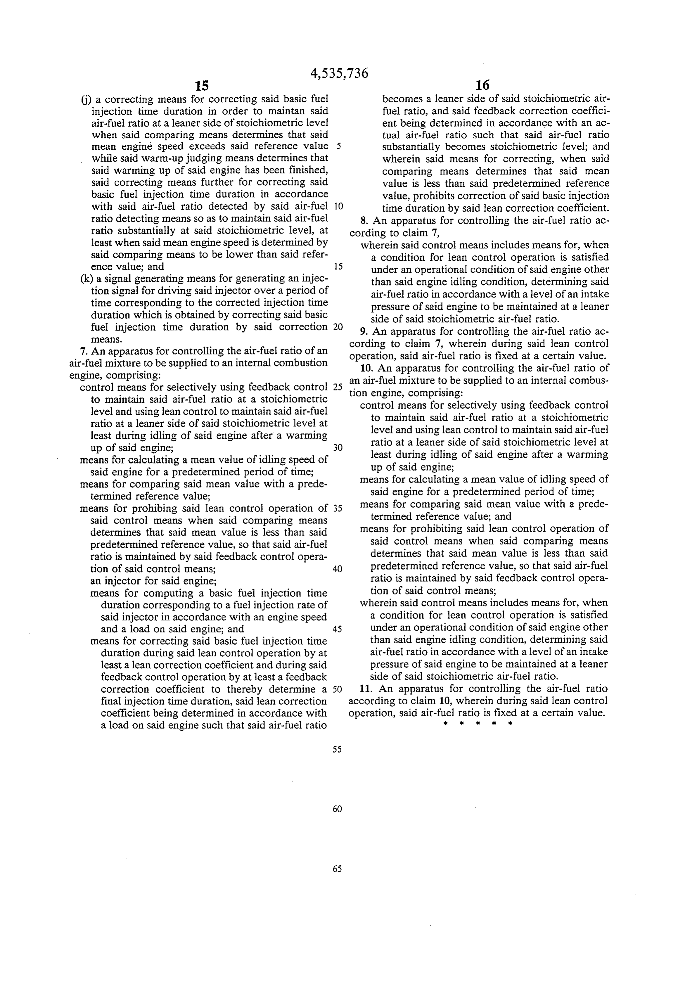
(j) a correcting means for correcting said basic fuel becomes a leaner side of said stoichiometric air injection time duration in order to maintan said fuel ratio, and said feedback correction coeffici air-fuel ratio at a leaner side of stoichiometric level ent being determined in accordance with an ac when said comparing means determines that said tual air-fuel ratio such that said air-fuel ratio mean engine speed exceeds said reference value 5 substantially becomes stoichiometric level; and while said warm-up judging means determines that wherein said means for correcting, when said said warming up of said engine has been finished, comparing means determines that said mean said correcting means further for correcting said value is less than said predetermined reference basic fuel injection time duration in accordance value, prohibits correction of said basic injection with said air-fuel ratio detected by said air-fuel 10 time duration by said lean correction coefficient. ratio detecting means so as to maintain said air-fuel 8. An apparatus for controlling the air-fuel ratio ac ratio substantially at said stoichiometric level, at cording to claim 7, least when said mean engine speed is determined by wherein said control means includes means for, when said comparing means to be lower than said refer a condition for lean control operation is satisfied ence value; and a 15 under an operational condition of said engine other (k) a signal generating means for generating an injec: than said engine idling condition, determining said tion signal for driving said injector over a period of air-fuel ratio in accordance with a level of an intake time corresponding to the corrected injection time pressure of said engine to be maintained at a leaner duration which is obtained by correcting said basic side of said stoichiometric air-fuel ratio. fuel injection time duration by said correction 20 9. An apparatus for controlling the air-fuel ratio ac
7. An apparatus for controlling the air-fuel ratio of an cording operation, to claim 7, wherein during said lean control said air-fuel ratio is fixed at a certain value.
air-fuel mixture to be supplied to an internal combustion 10. An apparatus for controlling the air-fuel ratio of engine, comprising: an air-fuel mixture to be supplied to an internal combus control means for selectively using feedback control 25 tion engine, comprising:
to maintain said air-fuel ratio at a stoichiometric level and using lean control to maintain said air-fuel control means for selectively using feedback control ratio at a leaner side of said stoichiometric level at to maintain said air-fuel ratio at a stoichiometric least during idling of said engine after a warming level and using lean control to maintain said air-fuel up of said engine; 3O ratio at a leaner side of said stoichiometric level at means for calculating a mean value of idling speed of least during idling of said engine after a warming said engine for a predetermined period of time; up of said engine;
means for comparing said mean value with a prede means for calculating a mean value of idling speed of termined reference value; said engine for a predetermined period of time; means for prohibing said lean control operation of 35 means for comparing said mean value with a prede said control means when said comparing means termined reference value; and determines that said mean value is less than said means for prohibiting said lean control operation of predetermined reference value, so that said air-fuel said control means when said comparing means ratio is maintained by said feedback control opera determines that said mean value is less than said tion of said control means; 40 predetermined reference value, so that said air-fuel an injector for said engine; ratio is maintained by said feedback control opera means for computing a basic fuel injection time tion of said control means;
duration corresponding to a fuel injection rate of wherein said control means includes means for, when said injector in accordance with an engine speed a condition for lean control operation is satisfied and a load on said engine; and 45 under an operational condition of said engine other means for correcting said basic fuel injection time than said engine idling condition, determining Said duration during said lean control operation by at air-fuel ratio in accordance with a level of an intake least a lean correction coefficient and during said pressure of said engine to be maintained at a leaner feedback control operation by at least a feedback side of said stoichiometric air-fuel ratio. correction coefficient to thereby determine a 50 11. An apparatus for controlling the air-fuel ratio final injection time duration, said lean correction according to claim 10, wherein during said lean control coefficient being determined in accordance with operation, said air-fuel ck ratiosk is kfixed at a certain value.
a load on said engine such that said air-fuel ratio
Provenance
- Collection
- Cited prior art
- Original PDF
- patentimages.storage.googleapis.com →
- Filed
- 1984-04-17
- Pages
- 23
- Method
- pdftotext (the PDF's own text layer) + pdftoppm 300dpi page scans
- Source
- Google Patents bibliographic record
- Granted
- 1985-08-20
- Inventors
- Mitsuharu Taura; Toshiaki Mizuno; Toyota Motor Corp
- Transcribed from
- patentimages.storage.googleapis.com →