patent · US4512304
Method and apparatus for controlling air to gas ratio in gas engines
23 April 1985
Page 1 — bibliographic record
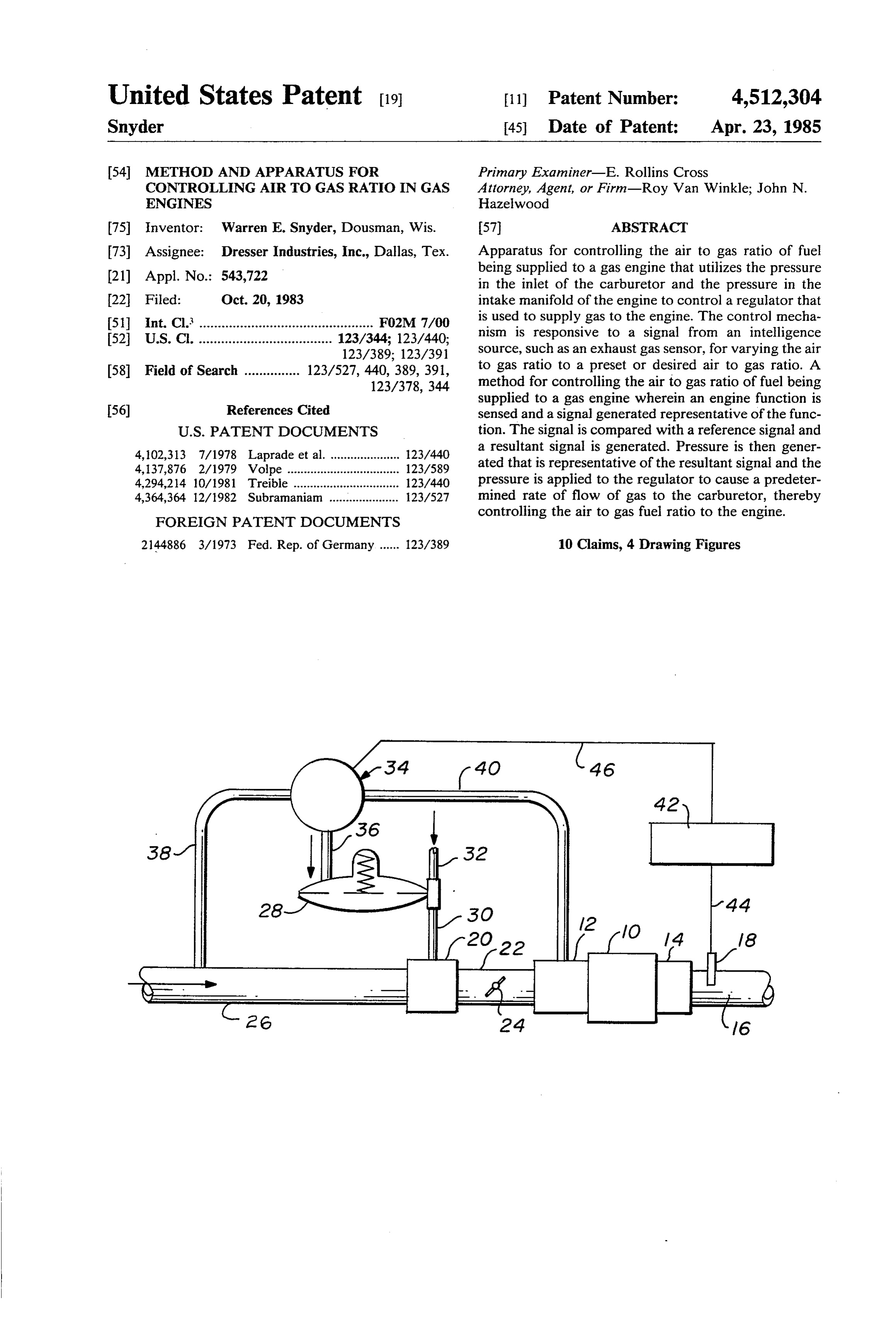
United States Patent (19) 11 Patent Number: 4,512,304 Snyder 45) Date of Patent: Apr. 23, 1985 54 METHOD AND APPARATUS FOR Primary Examiner-E. Rollins Cross CONTROLLING AR TO GAS RATO IN GAS Attorney, Agent, or Firm-Roy Van Winkle; John N. ENGINES Hazelwood 75 Inventor: Warren E. Snyder, Dousman, Wis. 57 ABSTRACT 73 Assignee: Dresser Industries, Inc., Dallas, Tex. Apparatus for controlling the air to gas ratio of fuel Appl. No.: 543,722 being supplied to a gas engine that utilizes the pressure (21) in the inlet of the carburetor and the pressure in the 22 Fied: Oct. 20, 1983 intake manifold of the engine to control a regulator that 51 Int. Cl. ............................................... FO2M 7/00 is used to supply gas to the engine. The control mecha 52 U.S. C. .................................... 123/344; 123/440; nism is responsive to a signal from an intelligence 123/389; 123/391 Source, such as an exhaust gas sensor, for varying the air 58 Field of Search ............... 123/527, 440, 389, 391, to gas ratio to a preset or desired air to gas ratio. A 123/378,344 method for controlling the air to gas ratio of fuel being supplied to a gas engine wherein an engine function is 56) References Cited sensed and a signal generated representative of the func
4,102,313 7/1978 Laprade et al. ..................... 123A40 a resultant signal is generated. Pressure is then gener 4,137,876 2/1979 Volpe .................................. 123/589 ated that is representative of the resultant signal and the 4.294,214 10/1981 Treible ................................ 123/440 pressure is applied to the regulator to cause a predeter 4,364,364 12/1982. Subramanian ..................... 123/527 mined rate of flow of gas to the carburetor, thereby
FOREIGN PATENT DOCUMENTS
controlling the air to gas fuel ratio to the engine.
2144886 3/1973 Fed. Rep. of Germany...... 123/389 10 Claims, 4 Drawing Figures
Page 2
Drawing sheet — no readable text.
Page 3
being supplied to a gas engine that includes intake and
METHOD AND APPARATUS FOR CONTROLLING exhaust manifolds, a carburetor having an air inlet and AIR TO GAS RATO IN GAS ENGINES having an outlet connected to the intake manifold, and a gas regulator connected to the carburetor for control
BACKGROUND OF THE INVENTION 5 ling the rate of flow of gas to the carburetor. The im This invention relates generally to apparatus and proved method comprises the steps of sensing an engine methods for controlling the air to gas ratio of fuel being function, generating a signal representative of the func supplied to gas (gaseous fueled) engines. More specifi tion, comparing the signal with a reference signal, gen cally, this invention relates to an improved apparatus O erating a resultant signal representative to the result of and method for controlling the air to gas ratio of fuel comparing the signals, generating a pressure representa being supplied to a gas engine wherein the regulator tive of the resultant signal, and applying the pressure to controlling the gas flow to the carburetor is actuated by the regulator causing a predetermined rate of flow of a pressure which varies between the pressure in the gas to the carburetor and thereby controlling the air to intake to the carburetor and the pressure in the intake 15 gas ratio of fuel mixture to the engine. manifold of the engine.
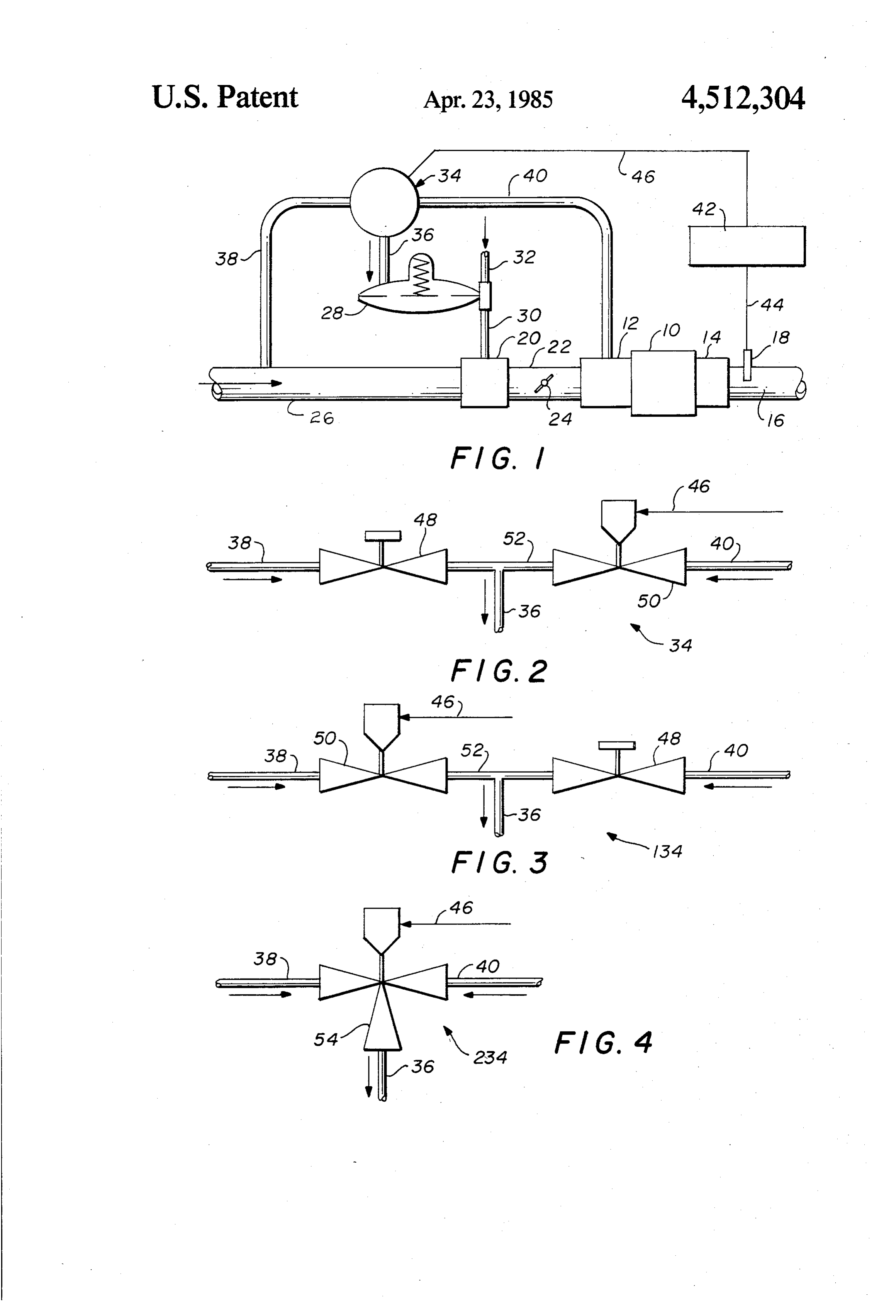
Carburated gas engines normally use at least one BRIEF DESCRIPTION OF THE DRAWING pressure regulator in the gas line to produce a con The foregoing and additional objects and advantages trolled pressure at the carburetor. The conventional will become more apparent as the following detailed regulator has a diaphragm that produces a force balance description is read in conjunction with the accompany between air pressure plus an adjustable spring force on 20 ing drawing, wherein like reference characters denote one side and the regulated gas pressure on the other. If like parts in all views, and wherein: the air pressure plus the adjustable spring force exceeds FIG. 1 is a schematic drawing illustrating apparatus the regulated gas pressure, the valve open and the gas constructed in accordance with the invention; pressure increases. If the regulated gas pressure exceeds the air pressure plus the adjustable spring force, the 25 utilized in theschematic
FIG. 2 is a invention of one type of pressure control illustrated in FIG. 1;
valve closes and the gas pressure decreases. FIG. 3 is another schematic diagram illustrating an The aforedescribed regulator provides a regulated other embodiment of control device that is utilized in pressure of gas to the carburetor in which the air fuel the invention illustrated in FIG. 1; and, ratio is presumably controlled. Relatively small changes in ambient conditions, however can cause the air fuel 30 thatFIG. 4 is still another embodiment of control device can be utilized in the invention illustrated in FIG. 1.
ratio to change and hence cause the engine to operate less efficiently. For example, changes in ambient tem DETAILED DESCRIPTION OF THE perature, humidity, engine temperature and fuel BTU PREFERRED EMBODIMENT content can all affect the efficiency.
At the present time, high operating efficiencies for 35 Referring to the drawing and to FIG. 1 in particular, the engine are very desirable and the high operating fold shown therein is a gas engine 10 that has an intake mani efficiencies are not available with the regulators utilized 12 and exhuast manifold 14 connected thereto. previously. Accordingly, it is an object of this invention Extending outwardly from the exhaust manifold 14 is an to provide a simple method and apparatus for control exhaust pipe 16 in which there is mounted an engine ling the air to gas ratio in gas engines that utilize the 40 function sensor 18. The sensor 18 may desirably be commercially available regulators, but, provide better sensing the ratio of air to fuel for the engine 10 com efficiencies than in engines operating with standard pared to stoichiometric. The precise function is not regulator systems. critical so long as air fuel ratio can be determined there from.
SUMMARY OF THE INVENTION 45 A carburetor 20 is connected to the intake manifold This invention provides in one aspect, improved ap by conduit 22 having a throttle valve 24 mounted paratus for controlling the air to gas ratio of the fuel therein. Extending outwardly from the carburetor 20 is mixture being supplied to a gas engine that includes an air inlet 26 which will usually include a filter (not intake and exhaust manifolds connected to the engine, a shown) and may include a turbocharger (not shown). carburetor having an air inlet and having an outlet con 50 A regulator 28, which is of the conventional dia nected to the intake manifold, and a gas regulator con phragm type, is arranged to supply gas to the carburetor nected to the carburetor for controlling the pressure of through a conduit 30. A conduit 32 extends from the gas to the carburetor. The improved apparatus com regulator to a source of gas (not shown). prises a conduit connecting the air inlet with the intake An actuator 34, which will be described more fully manifold and an actuator located in the conduit that is 55 hereinafter, consists of several components. The actua connected to the regulator. The actuator provides an tor 34 is connected with the regulator 28 by a conduit output pressure signal to the regulator of a magnitude 36, with the inlet 26 to the carburetor 20 by a conduit between the pressure in the inlet and the pressure in the 38, and with the intake manifold by a conduit 40. intake manifold, thus causing the regulator to supply the Operably disposed between the sensor 18 and the desired rate of flow of gas to the carburetor. The appa 60 actuator 34 is intelligence apparatus 42 which in the ratus also includes intelligence means connected to the preferred form, is an electronic system arranged to actuator for transmitting signal to the actuator whereby receive a signal from the sensor 18 and to compare that the actuator causes the regulator to provide the desired signal with a reference previously inserted into the rate of flow of gas to the carburetor and, consequently, apparatus 42. The system 42 is capable of generating an the desired air to gas ratio of fuel mixture supplied to 65 output signal related to the results of the comparison the engine. between the signal from the sensor 18 and the reference. In another aspect, this invention provides an im The signal from the sensor 18 is transmitted to the intel proved method for controlling the air to gas flow ratio ligence apparatus 42 by an electrical circuit 44 and from
Page 4
the apparatus 42 to the actuator 34 via an electric circuit main in a substantially fixed position, and the air to fuel 46. ratio should remain substantially constant until the ten The actuator 34 as previously mentioned, includes perature changes, the fuel quality varies or upon the several components. A more detailed schematic of the occurrence of some other factor affecting engine opera actuator 34 is shown in FIG. 2. tion. The sensor 18 is sensing the variations in the ex As illustrated therein, the actuator 34 includes a man haust manifold and continual comparison is being made ual valve or fixed orifice 48 that is connected to the to the standard signal in the apparatus 42. A constant conduit 38 that extends to the inlet 26. A variable or update of the air to fuel ratio is being transmitted to the control valve 50 is connected to the valve 48 by a con actuator 34 to cause the regulator 28 to supply the de duit 52 and has its opposite end connected to the intake O sired quantity of gas to the carburetor 20 as needed to manifold 12 by the conduit 40. The control signal from maintain the air fuel ratio at the desired value. the intelligence apparatus 42 is transmitted to the con Each of the modifications of the actuator 34 is capa trol valve 50 through electrical circuit 46. The actuator ble of performing this function. The type of intelligence 34, as illustrated in FIG. 2, is connected to the regulator apparatus 42 utilized will of course be strictly up to the 28 by the conduit 36 which has its opposite end con 15 user, with it being possible to use one of the number of nected to the conduit 52 between the valves 48 and 50. commercially available systems to perform the compar FIG. 3 illustates another modification of the actuator ing function.
that can be utilized in the system illustrated in FIG. 1. It will be understood that the foregoing is presented As shown in FIG. 3, the actuator is designated gener by way of example only and that many modifications ally by the reference character 134. The same reference 20 and changes can be made thereto without departing characters will be utilized on the same parts as previ from the spirit and scope of the invention. ously described in connection with FIG. 2. The embodiments of the invention in which an exclu As shown therein, the positions of the control valve sive property or privilege is claimed are defined as 50 and the manual valve or fixed orifice 48 have been follows:
reversed. In other words, the control valve 50 is con 25 1. Improved apparatus for controlling the air to gas nected to the conduit 38 that is connected to the inlet 26 ratio of fuel being supplied to a gas engine that includes of the carburetor 20. The valve 48 is connected by the intake and exhaust manifolds connected to the engine, a conduit 40 with the intake manifold 12. As previously carburetor having an air inlet and having an outlet con described, the electrical circuit 46 connects the control nected to the intake manifold, and a gas regulator con valve 50 with the intelligence apparatus 42. In opera nected to the carburetor for controlling the pressure of tion, the actuators 34 and 134 will work substantially gas to the carburetor, said improved apparatus compris the same, except in the actuator 134 the inlet pressure 1ng:
will be varied instead of the intake manifold pressure. conduit means connecting the air inlet with the intake FIG. 4 illustrates still another modification of the manifold;
actuator that can be utilized in the system illustrated in 35 actuating means located in said conduit means and FIG. 1. The actuator is designated by the reference connected to said regulator, said actuating means character 234 and includes a single controlled, three providing an output signal to said regulator that way valve 54 that has one inlet connected to the conduit has a magnitude equal to or between the pressure in 38 which extends to the inlet 26 to the carburetor 20 and said inlet and the pressure in said intake manifold a second inlet connected to the conduit 40 that which is for actuating said regulator to supply the desired connected to the intake manifold 12. The outlet from rate of flow of gas to said carburetor; and, the valve 54 is connected by the conduit 36 to the regu intelligence means connected to said regulator actuat lator 28 as previously described. The controlled three ing means for transmitting a signal to said actuating way valve 54 is connected by the electrical circuit 46 means whereby said actuating means causes said with the intelligence apparatus 42. In this actuator 234, 45 regulator to provide the desired rate of flow of gas the output in the conduit 36 and the valve 54 will be of to said carburetor and the desired air to gas ratio of a magnitude between the pressure in the conduit 38 and fuel supplied to said engine. the pressure in the conduit 40 in accordance with the 2. The apparatus of claim 1, wherein said actuating signal reaching the valve 54. means includes:
With the engine 10 operating, it can be seen that the 50 fixed control means in said conduit means; pressure in the inlet 26 and in the conduit 38 will be a conduit connecting said conduit means with said different from the pressure in the intake manifold 12 and regulator;
in the conduit 40. Thus, the actuator 34 is exposed to a variable control means spaced from said fixed control pressure difference thereacross. A sensor 18 senses means and connected to said intelligence means for Some engine function, such as, for example, the air fuel 55 determining the pressure applied to said regulator ratio as compared to Soichiometric and transmits a sig through said conduit to control the rate of flow of nal accordingly through the circuit 44 to the intelli gas supplied to said carburetor; and gence apparatus 42 wherein that signal is compared said conduit being disposed between said fixed and with a standard or reference signal. A resultant signal is variable control means.
then transmitted through the electrical circuit 46 to the 60 3. The apparatus of claim 2 wherein said intelligence actuator 34 and the appropriate pressure (somewhere means includes means for sensing an engine function, between the pressure in the conduit 38 and the pressure comparing said engine function with a reference, and in the conduit 40) is transmitted through the conduit 36 transmitting the resulting signal to said actuating means. to actuate the regulator 28, either reducing or increas 4. The apparatus of claim 2 wherein: ing the quantity of gas flowing through the conduit 30 65 said fixed control means is connected to said intake to the carburetor 20 as appropriate. manifold; and
As long as the engine 10 is operating at a generally said variable control means is connected to said air constant speed and load, the throttle valve 24 will re inlet.
Page 5
5. The apparatus of claim 2 wherein: generating a pressure by combining intake manifold said fixed control means is connected to said air inlet pressure and inlet air pressure that is representative whereby air inlet pressure is imposed on said fixed of said resultant signal; and, applying said generated pressure to said regulator control means; and, 5 causing a predetermined rate of flow of gas to said said variable control means is connected to said in carburetor and thereby, controlling the air to gas take manifold whereby inlet manifold pressure is ratio of fuel to said engine. imposed thereon. 8. The improved method of claim 7 wherein the step 6. The apparatus of claim 1 wherein said regulator O signalof generating a pressure representative of said resultant includes combining the intake manifold pressure actuating means includes a variable, flow restricting which has passed through a fixed flow restrictor with valve having inlets connected to said air inlet and to said the air inlet pressure which has passed through a vari intake manifold and having an outlet connected to said able flow restrictor that varies in response to said resul regulator, said valve being variable in response to the 5 tant signal and imposing the combined pressures on said regulator.
signal from said intelligence means. 9. The improved method of claim 7 wherein the step 7. An improved method for controlling the air to gas of generating a pressure representative of said resultant ratio of fuel being supplied to a gas engine that includes signal includes combining the intake manifold pressure intake and exhaust manifolds, a carburetor having an air which has passed through a variable flow restrictor that inlet and having an outlet connected to the intake mani 20 varies inlet in response to said resultant signal with the air pressure which has passed through a fixed flow fold, and a gas regulator connected to the carburetor for restrictor and imposing the combined pressure on said controlling the rate of flow of gas to the carburetor, the regulator.
improved method comprising the steps of: 10. The method of claim 7 wherein the step of gener sensing an engine function; 25 ating a pressure representative of said resultant signal generating a signal representative of said function; includes combining the air inlet and intake manifold comparing said signal with a reference signal; pressures in a variable, flow restricting mixing valve that varies in response to said resultant signal and im generating a resultant signal representative of the posing the combined pressures on said regulator. result of comparing said signals; 30 ck k sk :k ck
Provenance
- Collection
- Cited prior art
- Original PDF
- patentimages.storage.googleapis.com →
- Filed
- 1983-10-20
- Pages
- 5
- Method
- pdftotext (the PDF's own text layer) + pdftoppm 300dpi page scans
- Source
- Google Patents bibliographic record
- Granted
- 1985-04-23
- Inventors
- Warren E. Snyder; Dresser Industries Inc
- Transcribed from
- patentimages.storage.googleapis.com →