patent · US4250958
Double tubular thermal energy storage element
17 February 1981
Page 1 — bibliographic record
United States Patent (19) 11) 4,250,958 Wasserman 45) Feb. 17, 1981 (54) DOUBLE TUBULARTHERMAL ENERGY 3,744,272 7/1973 Oldberg ................................. 62/439 STORAGE ELEMENT . 4,104,185 8/1978 Schroder ...................... 165/104 S X
76) Inventor: Kurt J. Wasserman, P.O. Box 77, Primary Examiner-Albert W. Davis Port Jervis, N.Y. 12771 Attorney, Agent, or Firm-Jack D. Slobod 21 Appl. No.: 57,552 57 ABSTRACT 22 Filed: Jul. 16, 1979 An elongated flexible elastomer or plastic double tube structure for storing heat energy includes inner and 51 Int. Cli.............................................. F28D 21/00 outer flexible tubes held in coaxial relationship by inte 52 U.S. C. ........................................ 165/46; 62/439; gral angularly spaced apart webs which divide up the 165/104 S; 165/49; 165/53; 126/430; 219/325 annular space between the tubes into angularly spaced 58) Field of Search ................ 165/46, 104 S; 62/439, apart segments. The segments are filled with phase 62/530; 126/436, 400, 430; 219/325 change material such as salt hydrate. The annular space 56) References Cited is sealed at opposite ends by sealing the outer tube against the inner tube and the inner tube provides a
2,106,263 1/1938 Winter .......................... 165/104 S X water, through the structure. 2,146,058 2/1939 Doyle ................................ 62/439 X 3,462,968 8/1969 Puta et al. w & 888 swa was as a seasovo e o 165/46X 8 Claims, 5 Drawing Figures
Page 2
Drawing sheet — no readable text.
Page 3
Drawing sheet — no readable text.
Page 4
container for salt hydrate has a relatively small vertical
DOUBLE TUBULAR THERMAL ENERGY height for minimizing the effect of vertical separation of STORAGE EEMENT the salt hydrate.
FIELD OF THE INVENTION SUMMARY OF THE INVENTION
The present invention relates to thermal energy stor Briefly, the aforementioned and other objects of the age apparatus for heating or cooling purposes. In its invention are satisfied by providing thermal energy particular aspects the present invention relates to the storage apparatus which includes an elongated plastic provision of a phase change material within the annular 10 or elastomeric double tubular container composed of space defined between inner and outer flexible coaxial inner and outer tubes held in substantially coaxial rela tubes in order that a fluid may be run through the inner tionship by spacer means. A phase change material fills tube to carry thermal energy to or from the phase the annular space between the inner and outer tubes. change material. The annular space is sealed at opposite ends of the con BACKGROUND OF THE INVENTION 15 tainer by sealing the outer tube against the inner tube. A fluid such as water is circulated through the inner
Heretofore, many salt hydrates and their eutectics tube as means of heat transfer between the phase change have been identified which are useful in storing thermal material and a remotely located source of heat such as a energy for environmental heating or cooling use. Such solar collector. The inner and outer tubes are of the compounds generally have melting points ranging be same material. Therefore when salt hydrate is used as tween 40 degrees Fahrenheit and 120 degrees Fahren 20 the phase change material, the minute amount of mois heit and have a heat of fusion in excess of 50 BTU per ture diffusing from the salt hydrate through the wall of pound. The most well known of these compounds is the outer tube is balanced by moisture diffusing through sodium sulfate decahydrate (Na2SO4.10H2O).
When such a compound is sealed in a relatively thin 25 theThe wall of the inner tube into the salt hydrate. container is fashioned to be quite flexible and is walled plastic or elastomeric container, some water in the liquid phase of the compound is eventually lost by of a length that it may be bent 180 degrees without pinching the cross section of the container with a bend diffusion through the walls of the container, reducing radius on the order of three diameters or less. This the energy storage efficiency of the compound. construction enables the container to be laid horizon Another phenomenon which reduces the energy stor age efficiency of a salt hydrate compound is vertical 30 tally and successively bent back and forth over or separation of the compound due to incongruent melting alongside each succeeding horizontal span in order to in which, for example, in the case of sodium sulfate relatively tightly fill the space within walls, floors or decahydrate, some anhydrous sodium sulfate crystals ceilings of a building.
are formed which sink to the bottom of the container The spacer means is preferably in the form of a plural and are separated from water at the top of the container 35 ity of angularly spaced apart integral webs radially by a layer of sodium sulfate decahydrate crystals directed between the inner and outer tubes in order to formed therebetween. One solution to this problem has divide the annular space between the tubes into angu been the provision of elaborate means for mechanical larly separated segments. The segments preferably have mixing or stirring. Another solution proposed has been a maximum cross-section dimension of approximately the use of a clay-like homogenizing agent such as mag one-half inch, in order that when the container is laid nesium aluminum silicate. It is known that this vertical horizontally, there is insufficient vertical extent in each separation phenomenon does not markedly affect the salt hydrate filled segment to enable vertical separation energy storage efficiency of the salt hydrate if the effec of the components of the salt hydrate upon melting. tive vertical height of the container is no more than Furthermore, with the addition of well-known thicken about one-half inch. 45 ing and nucleating agents to the salt hydrate, larger Another difficulty which has existed concerning the cross-sectional dimensions may be used. use of salt hydrate for thermal energy storage is that no Other objects, features and advantages of the present suitable container therefor has been available which invention will become apparent upon perusal of the may be housed within walls, ceilings or floors of a build following description of the preferred embodiments of
the invention when taken in conjunction with the ap
OBJECTS OF THE INVENTION pended drawing wherein:
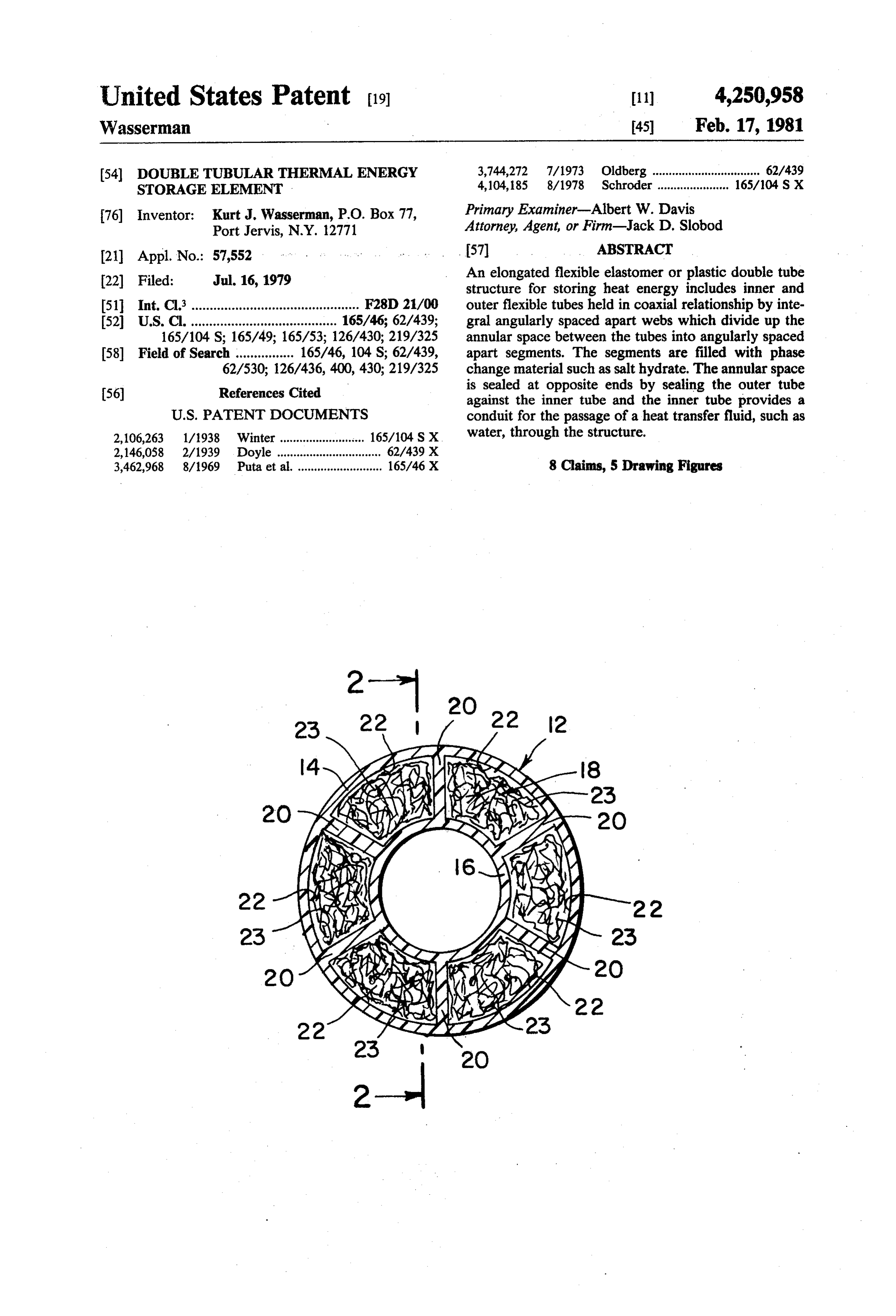
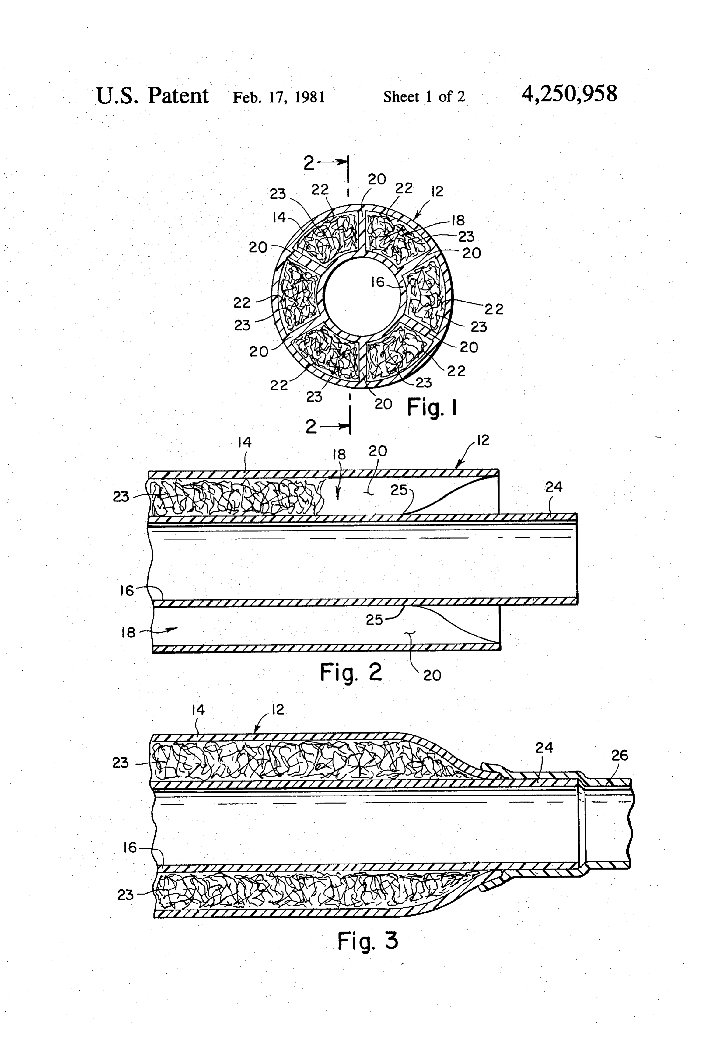
It is an object of the present invention to provide heat BRIEF DESCRIPTION OF THE DRAWING energy storage apparatus in which a container for phase FIG. 1 is a transverse cross-sectional view of the change material includes a means for heat transfer to or 55 thermal energy storage apparatus of the present inven from the phase change material.
It is another object of the present invention to pro tion;
vide an energy storage apparatus in which a container FIG. 2 is a longitudinal cross-sectional view taken for salt hydrate is configured to enable water flow used but priorlines through 2-2 in FIG. 1 at one end of the apparatus to sealing;
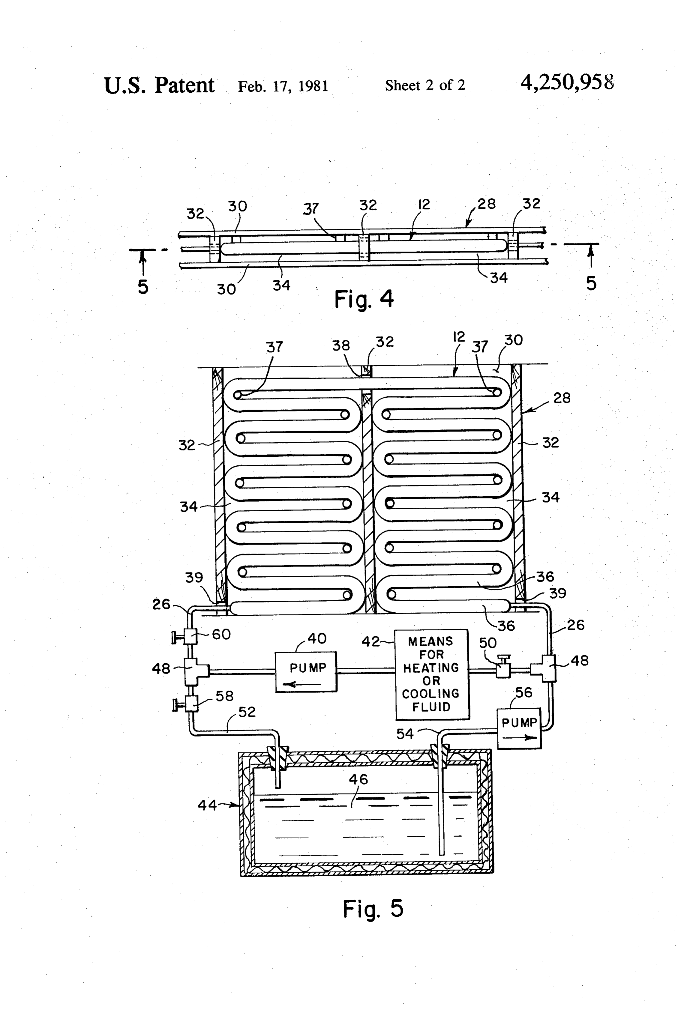
for energy transfer to replace moisture lost from the salt 60 hydrate. FIG. 3 is a longitudinal cross-sectional view of the It is a further object of the present invention to pro same end as in FIG. 2 but after sealing; vide an elongated flexible container for phase change FIG. 4 is a top view of a wall in which the thermal material which may be bent back and forth over or energy storage apparatus of the present invention is alongside itself in order to fill space within building 65 installed; and walls, ceilings or floors. FIG. 5 is an elevational cross-sectional view through It is yet another object of the present invention to the lines 4-4 in FIG. 4 in conjunction with a system for provide thermal energy storage apparatus in which a supplying heat transfer fluid thereto.
Page 5
DETAILED DESCRIPTION OF THE thermal contact between phase change material 23 and PREFERRED EMBODIMENTS the inner tubular portion 16.
Prior to filling mernber 12 with the phase change
In accordance with the principles of the present in material, each end of member 12, as illustrated in FIG. vention, with reference primarily to FIG. 1 of the draw 2, is prepared to enable sealing of annular space 18. In ing, storage apparatus is provided which comprises an order to accomplish this, the outer tubular portion 14 is elongated, flexible, preferably integral extruded double cut back to expose a short length 24, on the order of 3 tubular member 12 of plastic or elastomeric material. of an inch, of the inner tubular portion 16 which Member 12 is preferably of polyolefin plastic, cross projects from the end of member 2. Further, webs 20 linked polyolefin, EPDM or EPT synthetic rubber O are cut back along an inclined line starting at the end of (ethylene-propylene-terpolymer) and is preferably at outer tubular portion 14 and ending at a point 25 on least eight feet and up to several hundred feet in length, inner tubular portion 16 about 3 inch longitudinally generally 25-50 feet, and has a substantially constant back within member 12. As shown in FIG. 3, this relief wall thickness on the order of one-sixteenth to one of webs 20 allows the end of outer tubular portion 4 to eighth of an inch. The plastic or elastomeric material 15 be bent radially inward against tubular portion 16 and utilized for the extrusion preferably is filled about 35 sealed against portion 16 by adhesive or when the mate percent by weight with a thermally conductive material rial of member 12 permits, as when it is extruded of such as a metallic oxide, carbon black or metallic flakes polyolefin by heat sealing. In this manner first one end to render all the walls of member 12 substantially ther of member 12 is sealed, then while the temperature is mally conductive. maintained so as to keep the phase change material 23 in Member 12 includes an outer tubular portion 14, a substantially liquid or flowable semisolid, the material about 1 inches in diameter and an inner tubular portion is forced into the cavities 22 through the other end of 16 about inch in diameter. Tubular-portions 14 and 16 member 12, Thereafter the other end of member 2 is are concentric with each other and define an annular sealed in the same manner.
space 18 therebetween. Directed radially between the 25 It will thus be appreciated that the annular space 18 of inner and outer tubular portions 14 and 16 within space member 12 is filled with phase change material 23 and 18 are a plurality of equi-angularly spaced apart integral the annular space is sealed at both ends. The inner tubu webs 20 of the same wall thickness as the walls of tubu lar member 16 provides a conduit for the passage of a lar portions 14 and 16. Six webs 20 are preferably so heat transfer fluid, such as water, to be run in intimate provided to divide up annular space 18 into preferably 30 thermal contact with phase change material 23 in view six cavities or segments 22. - of the thermally conductive nature of all the walls of Member 12 is provided to have sufficient flexibility in member 12. In order to permit such passage of heat order that a bend of 180 degrees in member 12 with a transfer fluid a different plastic, elastomeric or metal bend radius of three diameters will not pinch off the tube 26 is inserted over or within each projecting end 24 cross-section of member 2. 35 of tubular portion 16 and adhesively secured thereto. It should thus be apparent that member 12 comprises Again, heat sealing may be utilized in place of adhesive an outer tubular portion 16 and an inner tubular portion if the materials of tube 26 and member 12 permit. 14 and a spacer means in the form of webs 20, all inte It will be further appreciated that by utilizing water grally extruded. as the heat transferring fluid within the inner tubular Each of cavities 22 is filled throughout the length of 40 portion 16, when the phase change material 23 is a salt member 12 with a phase change material 23 having a hydrate, any water lost from the salt hydrate by diffu heat of fusion in excess of 50 BTU per pound and a sion through outer tubular portion 4 will be replaced melting point or transition temperature ranging be by diffusion of some of the heat transfer water through tween 40 and 120 degrees Fahrenheit. Suitable phase the inner tubular portion 16. Further, with the member change materials are divided into three main categories; 45 12, directed in a generally horizontal orientation, the those with a melting point generally between 40' and cavities 22, being in the order of one-half inch in maxi 65. Fahrenheit and therefore suitable for storage of mum cross-sectional dimension, are sufficiently small in coolness, those with a melting point generally in the vertical extent to prevent the lack of reversibility and range of 65-75 Fahrenheit and suitable for room tem consequent loss of energy storage efficiency which perature stabilization, and those with a melting point 50 occurs with the incongruent melting and gravitational generally between 75 and 120 Fahrenheit and suitable separation of the salt hydrate. Further, with the use of for heat storage applications. Most preferable for use as thickening and nucleating agents as described in the a phase change material to fill annuiar. space 18 are salt aforementioned U.S. Pat, No. 3,986,969 to Maria hydrates and their eutectics. Generally salt hydrates Telkes, the maximum cross-sectional dimensions of the and their eutectics may be produced with any melting 55 cavities 22 may be larger than one-half inch because of point desired within the range of 40' F. to 120 F. U.S. the avoidance of gravitational separation of the salt Pat. No. 2,989,856 granted June 27, 1971 to Maria hydrate.
Telkes is herein incorporated by reference. Therein, Referring to FIGS. 4 and 5 of the drawing, member examples of salt hydrate eutectics are disclosed for 12 when filled with phase change material and sealed melting points of 40' F., 52 F., 64 F., and in the range 60 according to the foregoing is used in conjunction with a of 70 F. to 75° F. Further, many salt hydrates have preferably internal wall 28 of a building. Wall 28 con melting points in the range useful for heating purposes. sists of opposed wall sheets 30 spaced apart by vertical These are detailed in U.S. Pat. No. 3,986,969 granted studs 32 which define a plurality of cavities 34 between Oct. 19, 1976 to Maria Telkes and includes Sodium the studs and wall sheets. The wall sheets are preferably Sulfate Decahydrate (NA2SO4.10H2O), the most well 65 metal plates or other substantially thermally conductive known salt hydrate for heat storage purposes. material. During the construction of wall 28, the mem The webs 20 and the tubular portions 14 and 16, being ber 12 is placed within the cavities 34 by running hori substantially thermally conductive, provide intimate zontal spans 36 of member 12, folding member 22, 180
Page 6
degrees at the end of each span in order to lay each off. These conditions produce heat transfer fluid circu successive span on top of the preceding span to fill lation between means 42 and member 12. Once the heat substantially the entire cavity 34. In order to support transfer fluid approaches its boiling point, or the heat spans 36 regularly spaced apart and in a horizontal given off by member 12 to the surrounding environment orientation, pegs or dowels 37 may be provided project becomes excessive, the valve 60 is closed, the valve 58 ing from one of wall sheets 30 to support member 12 at is opened, and pump 56 is also turned on. These condi each point where it is bent. It is thus important that tions set up heat transfer fluid circulation between the member 12 be sufficiently flexible to be bent 180 degrees means 42 and tank 44, by which the water 46 in the tank with a radius on the order of three outside diameters of is heated by means 42 and stored for later use. Then member 12 or less without pinching off the cross-sec O when it is desired to circulate the water in tank 44 tion of member 12 and obstructing the flow of heat through member 12 for heating purposes, pump 40 is transferring fluid therethrough. Further as illustrated, a turned off, valve 50 is closed and valve 60 is opened. plurality of cavities 34 might be filled with one continu Thus, pump 56 circulates the water 46 in tank 44 ous length of member 12 by providing a notch or hole through member 12.
38 in the stud 32 between adjoining cavities 34 to permit 15 Additionally, the entire system of FIGS. 4 and 5 o passage of member 12 therethrough. The tubes 26 at the drawing might be automated in an obvious fashion tached to opposite ends of member 12 exit wall 30 by replacing the manual valves 50, 58, and 60 with through suitable holes 39 and are coupled together solenoid type valves and controlling the on-off states of through a suitable electric pump 40 for recirculating the the electric pumps 40 and 56 and the opened-closed heat transferring fluid through the inner tubular portion states of the valves by thermostatic controls responsive of member 12, and suitable means 42 in series with pump to ambient and transfer fluid temperatures. 40 and remote from wall 28 for heating or cooling the Other applications of the present invention are possi heat transfer fluid. Whether heating or cooling means ble in which are used depends on the application and the consequent mote location member 12 is for example coiled in a re from the space to be heated or cooled and selection of the phase change material 23. 25
In heating applications, the means 42 preferably com the fluid means 42 for heating or cooling the heat transfer is selectively replaced by a radiator located within prises a solar energy collector. In view of rate advan the space tages given by electric companies for night consump utilize thetoheat be heated or cooled, when it is desired to tion, it is also feasible to utilize the member 12, with the temperatureorofcold stored in member 12 to control the space.
appropriate selection of the phase change material 23 as 30 Furthermore, member 12 might be provided inte previously indicated, for cooling applications in which grated into prefabricated wall panels, or might be laid the phase change material is cooled during the evening by utilizing the means 42 as suitable refrigeration device with successive horizontal spans alongside each other for cooling the heat transfer fluid. Thus the coolness within a floor. Additionally, member 12, rather than might be stored to cool the building or structure during 35 being within a wall might be laid in a horizontal serpen the day. tine fashion against a wall to also achieve a decorative In heating applications, heat stored in member 12 is effect.
slowly transferred to the interior of the building While the preferred embodiments of the present in through the wall sheets 30 while in cooling applications, vention have been described in specific detail, it should heat is slowly taken in by the member 12 also through be appreciated that numerous modifications, substitu wall sheets 30. Furthermore, upper and lower vents tions, additions and deletions in and to said details are (not shown) through wall sheets 30, might be provided possible within the intended spirit and scope of the in association with a fan (also not shown) positioned for present invention.
I claim:
setting up air currents flowing over member 12 and through these vents for additional heat transfer with the 45 1. A thermal energy storage and transfer apparatus interior of the building. comprising:
It will be appreciated that when water is used as the an elongated tubular container, said container com heat transfer fluid, it may properly be heated by means prising thermally conductive flexible inner and 42 only to a temperature below the boiling point of outer tubes defining an annular space therebetween water, since the member 12 is not capable of withstand 50 and spacer means for maintaining said inner and ing the pressure of steam. Once this point is approached, outer tubes in substantially coaxial relationship, the electric pump 40 would normally have to be turned said tubes being composed of materials selected off to prevent further transfer fluid circulation through from plastics and elastomers; member 12. However, with the addition of a large ther a phase change material having a heat of fusion of mally insulated storage tank 44 of water 46, the means 55 more than 50 BTU per pound and a melting point 42 might be utilized to heat the water in tank 44, which ranging between 40 and 120 degrees Fahrenheit heated water 46 might be used at a later time for circula within said annular space; and tion through member 12. Thus the tubes 26 are con sealing means sealing said annular space at opposite nected to tees 48 which couple member 12 to a first fluid ends of said container, said inner tube providing a path consisting of pump 40, means 42, and a manual 60 conduit for running heat transferring fluid through - Valve 50; and a second path consisting of the storage said container in thermal contact with said phase tank 46, via input pipe 52 and output pipe 54 sealably change material;
entering the tank, a second electric pump 56, and a said spacer means comprising a plurality of angularly manual valve 58. Furthermore, a third manual valve 60 spaced apart webs spanning substantially the entire is provided in series with one of pipes 26 between mem 65 length of said container and being radially directed ber 12 and one of the tees 48. between the inner and outer tubes, said webs divid In normal operation, valves 50 and 60 are open, pump ing said annular space into a plurality of elongated 40 is turned on, valve 58 is closed and pump 56 turned angularly spaced apart cavities between said webs,
Page 7
said phase change material being within said cavi tween 40 and 120 degrees Fahrenheit within said ties. annular space; and 2. The apparatus of claim 1 wherein said inner and sealing means sealing said annular space at opposite outer tubes and said spacer means comprise an integral ends of said container, said inner tube providing a structure. conduit for running heat transferring fluid through 3. The apparatus of claim 1 wherein said phase said container in thermal contact with said phase change material consists essentially of salt hydrate. change material;
4. The apparatus of claim 2 wherein said phase said spacer means comprising a plurality of angularly change material consists essentially of salt hydrate. spaced apart webs spanning substantially the entire 5. The apparatus of claim 1 wherein the walls of said 10 length of said container and being radially directed inner and outer tubes have substantially the same per between the inner and outer tubes, said webs divid meabilities to the diffusion of water therethrough. ing said annular space into a plurality of elongated 6. A thermal energy storage and transfer apparatus angularly spaced apart cavities, said webs and said comprising: sealing means being configured to prevent commu an elongated tubular container, said container com 15 nication between said cavities, said phase change prising thermally conductive flexible inner and material being within said cavities. outer tubes defining an annular space therebe 7. The apparatus of claim 6 wherein said inner and tween, and spacer means for maintaining said inner outer tubes and said spacer means comprise an integral and outer tubes in substantially coaxial relation structure.
ship; 20 8. The apparatus of claim 6 wherein the walls of said a phase change material consisting essentially of salt inner and outer tubes have substantially the same per hydrate having a heat of fusion of more than 50 meabilities to the diffusion of water
therethrough.
BTU per pound and a melting point ranging be
Provenance
- Collection
- Cited prior art
- Original PDF
- patentimages.storage.googleapis.com →
- Filed
- 1979-07-16
- Pages
- 7
- Method
- pdftotext (the PDF's own text layer) + pdftoppm 300dpi page scans
- Source
- Google Patents bibliographic record
- Granted
- 1981-02-17
- Inventors
- Kurt J. Wasserman
- Transcribed from
- patentimages.storage.googleapis.com →