patent · US4065053
Low cost solar energy collection system
27 December 1977
Page 1 — bibliographic record
United States Patent (19) (11) 4,065,053 Fletcher et al. 45 Dec. 27, 1977 (54) LOW COST SOLAR ENERGY COLLECTION Assistant Examiner-James C. Yeung SYSTEM Attorney, Agent, or Firm-Monte F. Mott; Wilfred .Grifka; John R. Manning 76) Inventors: James C. Fletcher, Administrator of the National Aeronautics and Space (57) ABSTRACT
Administration, with respect to an A fixed, linear, ground-based primary reflector having invention of Charles G. Miller, an extended curved-sawtooth contoured surface cov Pasadena; James B. Stephens, La ered with a metallized polymeric reflecting material, Crescenta, both of Calif. reflects solar energy to a movably supported collector (21) Appl. No.: 598,969 that is kept at the concentrated line focus of the reflec tor primary. The primary reflector may be constructed 22 Filed: July 24, 1975 by a process utilizing well-known freeway paving ma (51) Int. Cl’................................................. F24J 3/02 chinery. The solar energy absorber is preferably a fluid (52) U.S. C. ..................................... 237/1 A; 60/641; transporting pipe. Efficient utilization leading to high 62/4; 126/271; 126/263; 165/2 temperatures from the reflected solar energy is obtained (58) Field of Search ............... 126/270, 271, 400, 263; by cylindrical shaped secondary reflectors that direct 237/1 A; 62/4, 467; 165/2, 107; 60/641 off-angle energy to the absorber pipe. To obtain higher (56) References Cited temperature levels, refocusing secondary reflectors, that cause a series of discrete spots of highly concen
1,047,554 12/1912 Nichols ................................ 126/271 are utilized. A seriatim arrangement of cylindrical sec 2,864,671 12/1958 Mohlman ........ ... 23/212 ondary reflector stages and spot-forming reflector 3,075,361 1/1963 Lindberg, Jr. .. a - - -- 62/4 stages produces a high temperature solar energy collec 3,182,654 5/1965 Culling .................... s s 126/270 tion system of greater efficiency. 3,868,823 3/1975 Russell, Jr. et al. ................. 126/270
Primary Examiner-Kenneth W. Sprague 17 Claims, 28 Drawing Figures
Page 2
Drawing sheet — no readable text.
Page 3
Drawing sheet — no readable text.
Page 4
Drawing sheet — no readable text.
Page 5
Drawing sheet — no readable text.
Page 6
Drawing sheet — no readable text.
Page 7
Drawing sheet — no readable text.
Page 8
Drawing sheet — no readable text.
Page 9
Drawing sheet — no readable text.
Page 10
Drawing sheet — no readable text.
Page 11
Drawing sheet — no readable text.
Page 12
Drawing sheet — no readable text.
Page 13
Drawing sheet — no readable text.
Page 14
Drawing sheet — no readable text.
Page 15
Still another object of this invention is to provide a
LOW COST SOLAR ENERGY COLLECTION process for relatively inexpensively making a large lin SYSTEM ear fixed primary reflector for tracking solar energy collection systems.
ORIGIN OF THE INVENTION Still a further object of this invention is to provide a The invention described herein was made in the per large-scale solar power system that is sufficiently effi formance of work under a NASA contrast and is sub .cient and cost effective to be competitively attractive. ject to the provisions of Section 305 of the National These objects and the general purpose of this inven Aeronautics and Space Act of 1958, Public Law 85-568 10 tion are accomplished in the following manner. A large (72 Stat. 435; 42 U.S.C. 2457). fixed primary reflector is constructed at ground level by
BACKGROUND OF THE INVENTION
slip-forming in concrete or stabilized dirt a trough with a segmented one-dimensional circular cross-section
The present invention relates generally to improve profile. This profile is covered with an inexpensive ments in solar energy collection systems and more par 15 light-reflective material. The axis of the primary reflec ticularly pertains to new and improved sun-tracking tor is optimally aligned with respect to the sun path in solar energy collection systems that are capable of pro the area. A heat-absorbing structure is movably sup ducing high solar energy concentration ratios. ported above the primary reflector. The support mech The overriding problem confronting developers of anism transversely shifts the heat-absorbing structure to solar energy power systems has been the problem of track the changing position of the sun's image diurnally producing the required high temperatures at a cost that 20 and seasonally, keeping the structure at the changing would make the utilization of solar power competi line focus of the primary reflector. The heat-absorbing tively attractive. Presently, systems capable of produc structure carries secondary reflectors that either direct ing the required high temperatures directly from solar off-angle solar energy to the structure or refocus the energy, utilize tracking devices with large moving pri 25 line focus of the primary reflector into discrete spots of mary reflectors. Accurate tracking devices, however, intense solar energy. These secondary reflectors are are expensive to construct and costly to maintain if they constructed so as to maximize absorption and minimize are to track under conditions of weather extremes and heat emission from the heat-absorbing structure. Build varying high wind forces. The cost of producing large ing the solar energy collection system in stages, each tracking reflectors and the costs of an associated track 30 stage designed for optimum efficiency within a certain ing mechanism sturdy enough to withstand expected temperature range, provides a more efficient and cost wind forces make a solar energy heat generating plant effective overall system.
that can provide sufficient power to produce electricity BRIEF DESCRIPTION OF THE DRAWINGS in the multi-megawatt range an uneconomical prospect.
Solar energy collection systems that are to be used 35 Other objects and many of the attendant advantages for producing superheated steam for use by steam of this invention will be readily appreciated as the same driven generator equipment for generating electric becomes better understood by reference to the follow power must be capable of transforming solar energy ing detailed description when considered in conjunction into thermal energy in the range of 1000 F or higher. with the accompanying drawings in which like-refer The prior art systems capable of such heat generation ence numberals designate like parts throughout the involve tracking concentrators such as three-dimen figures thereof and wherein:
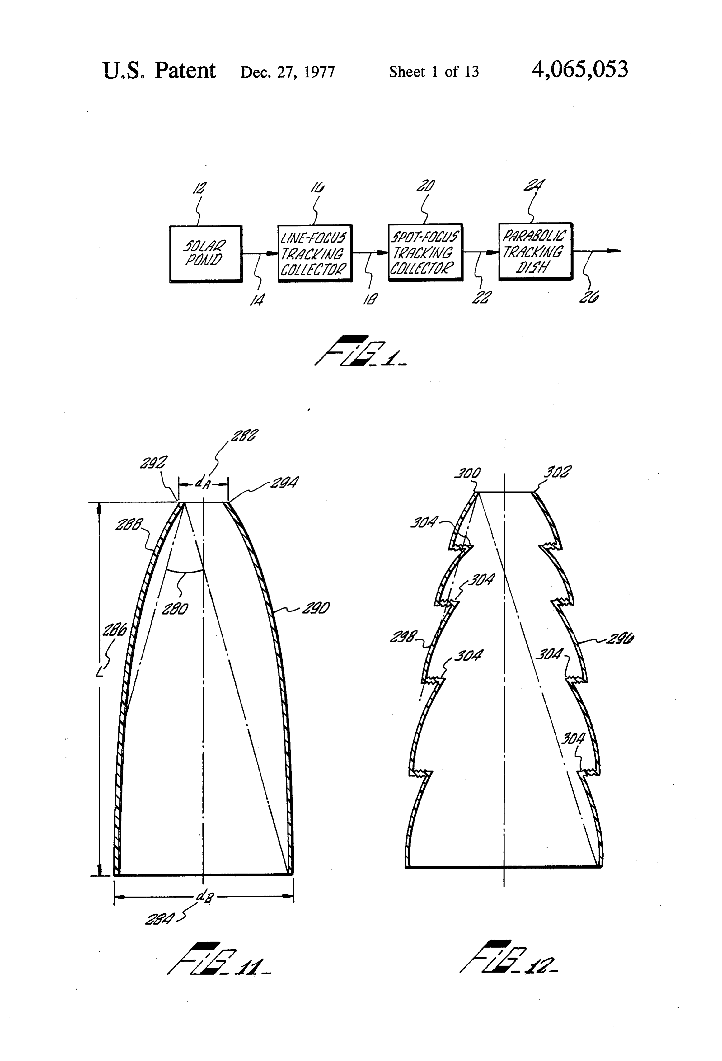
sional paraboloidaldishes which can be precisely FIG. 1 is a block diagram of a staged solar energy steered in both altitude and azimuth to follow the sun's collection system;
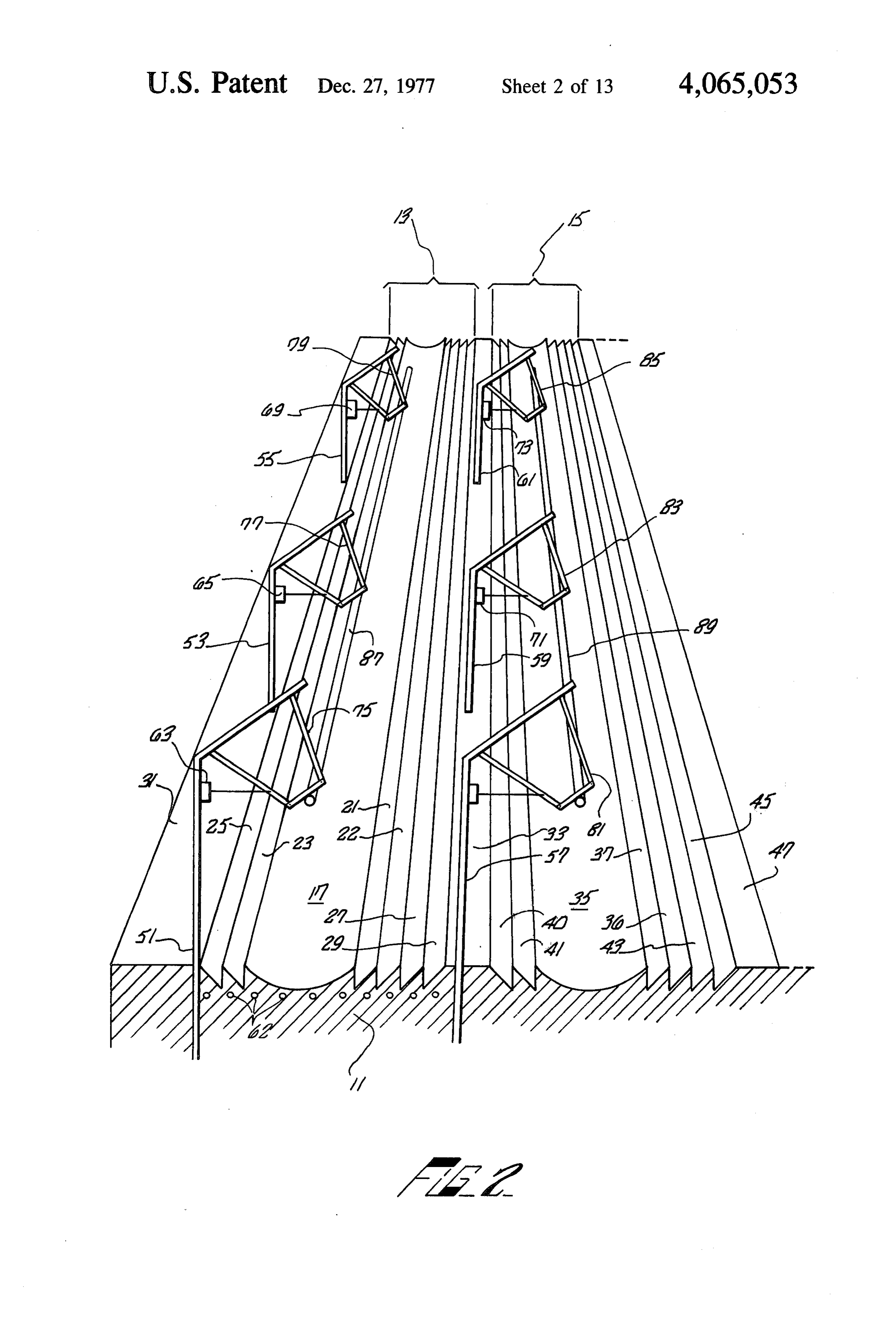
movement. In order to generate temperatures in the FIG. 2 is a perspective, partial section, illustrating a range of 1000 F in sufficient quantity for use as energy 45 solar energy collection system according to the present for the generation of electrical power, literally thou invention;
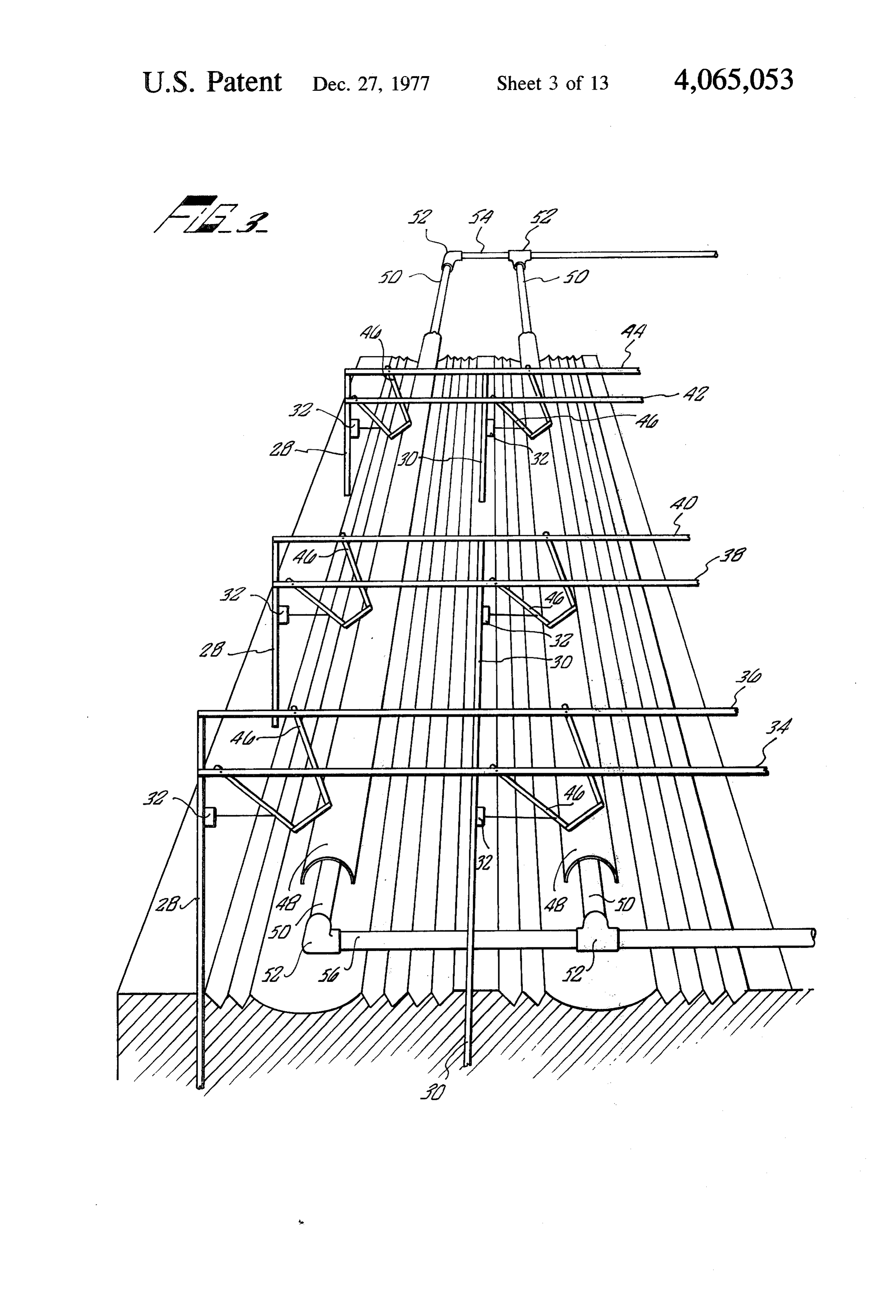
sands of 20-foot diameter, three-dimensional parabolic FIG. 3 is a perspective, partial section, illustrating a dishes must be utilized. The cost of producing large solar energy collection system according to the present numbers of such optically finished compound curve invention;
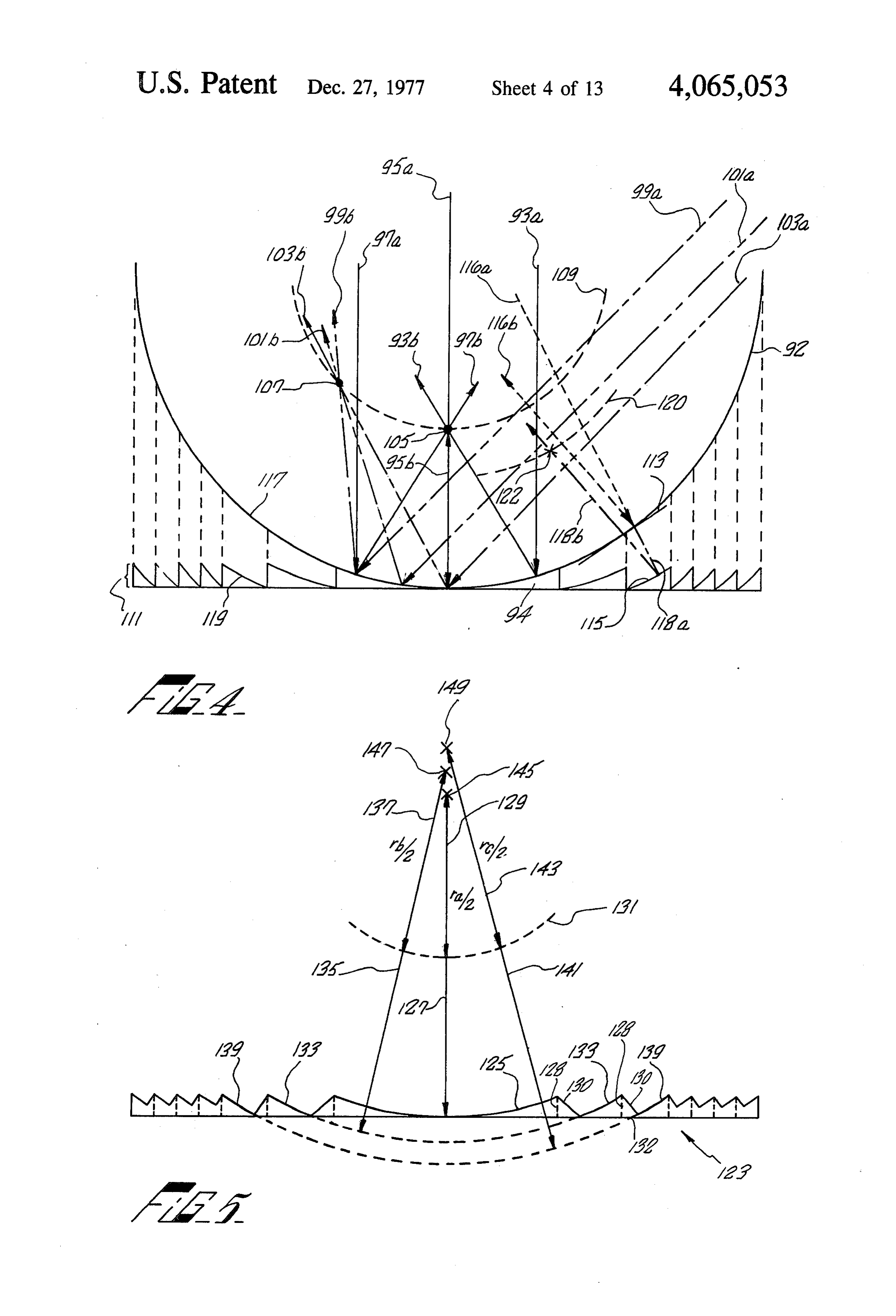
reflecting surfaces that are sturdy enough to hold their 50 FIG. 4 is a diagrammatic illustration, useful in ex figure when tilted and turned in the wind is prohibitive. plaining the principle of the large-scale primary reflec
OBJECTS AND SUMMARY OF THE
tor of the present invention;
FIG. 5 is a diagrammatic illustration, useful in ex
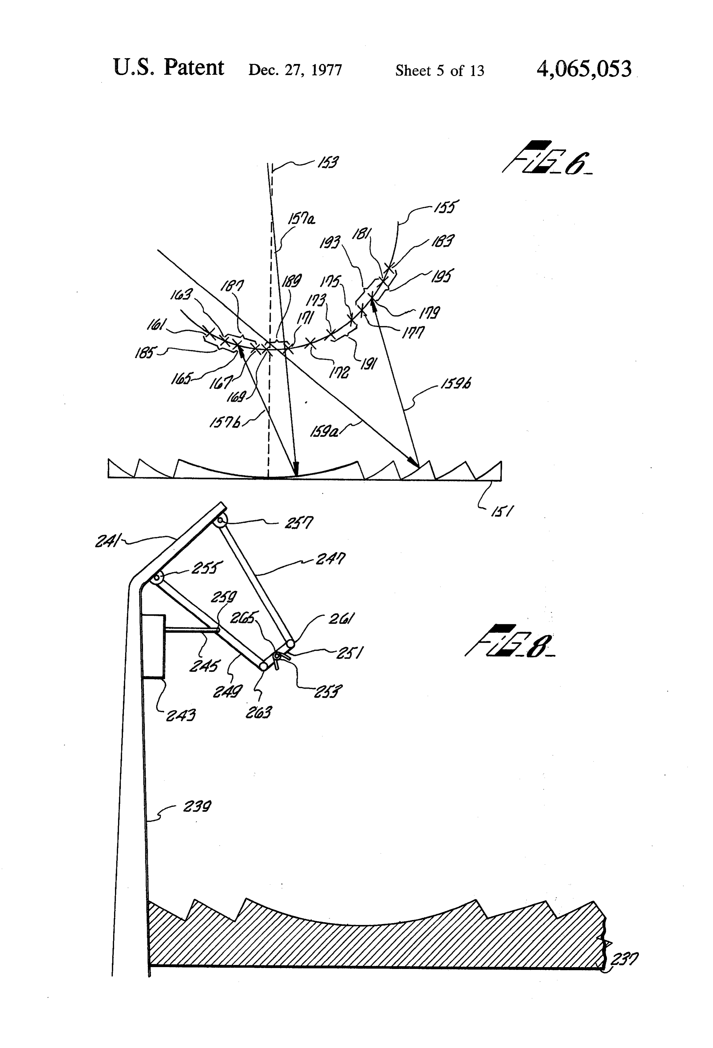
INVENTION plaining the desired structure of the large-scale primary An object of this invention is to provide an inexpen 55 reflector of the present invention; sive, high temperature solar energy collection system. FIG. 6 is a diagrammatic illustration of the daily and Another object of this invention is to provide a track seasonal adjustments required by the collector system ing solar energy collection system utilizing a fixed, of the present invention;
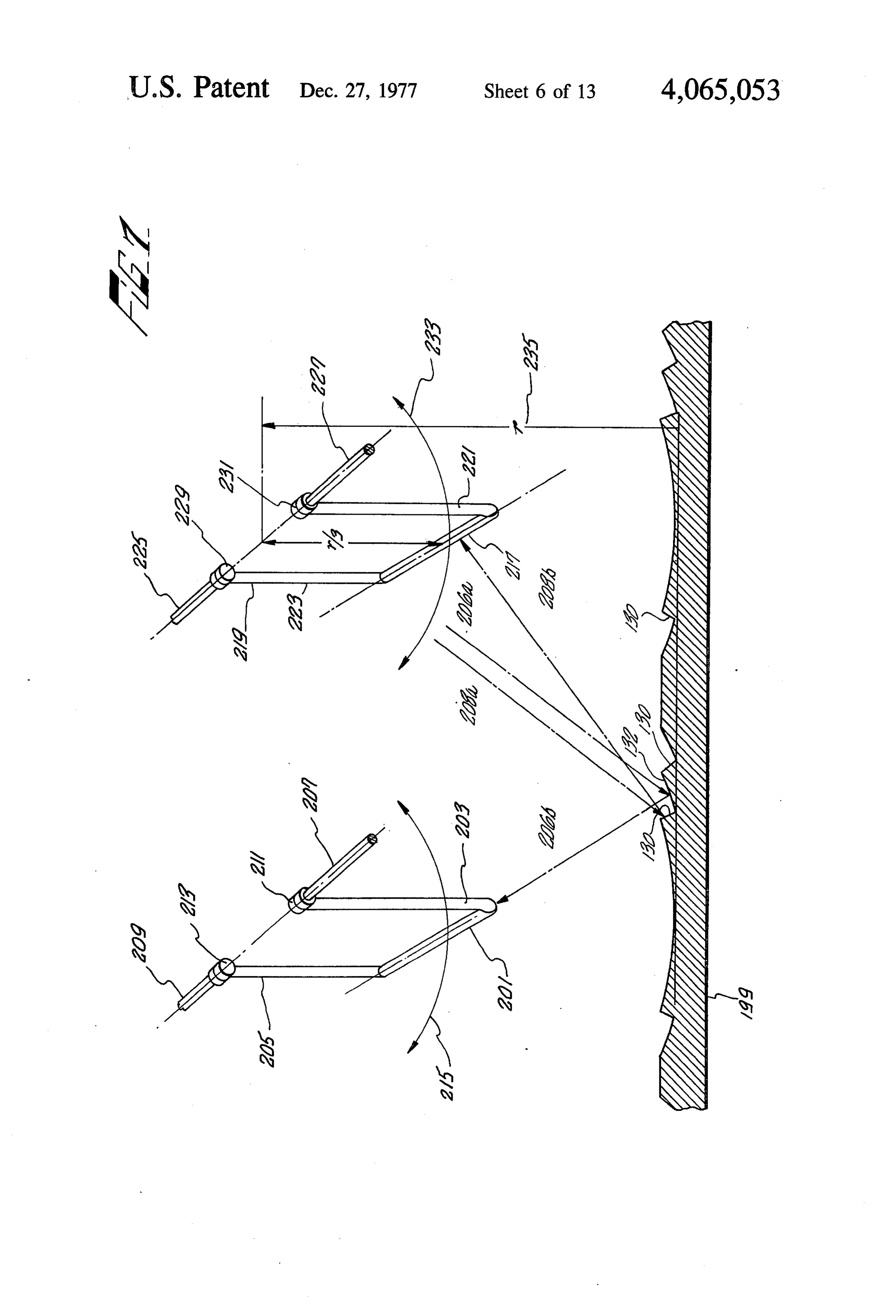
linear, ground-based primary reflector and a movably FIG. 7 is a partial perspective illustration of a type of supported collector. laterally movable collector system and a cross section A further object of this invention is to provide secon of the largescale reflector of the present invention; dary reflectors for refocusing the solar energy reflected FIG. 8 is a diagrammatic illustration of one type of from a fixed concentrator into concentrated beams of laterally movable supporting structure for the collec solar energy. tors of the present invention; Yet another object of this invention is to provide FIG. 9 is a schematic illustration of the operation of secondary reflectors that substantially increase absorp the laterally movable supporting structure of FIG. 8; tion of visible light and reduce emission of heat rays FIG. 10A is a perspective illustration of a secondary from the collector. reflector of the present invention;
Page 16
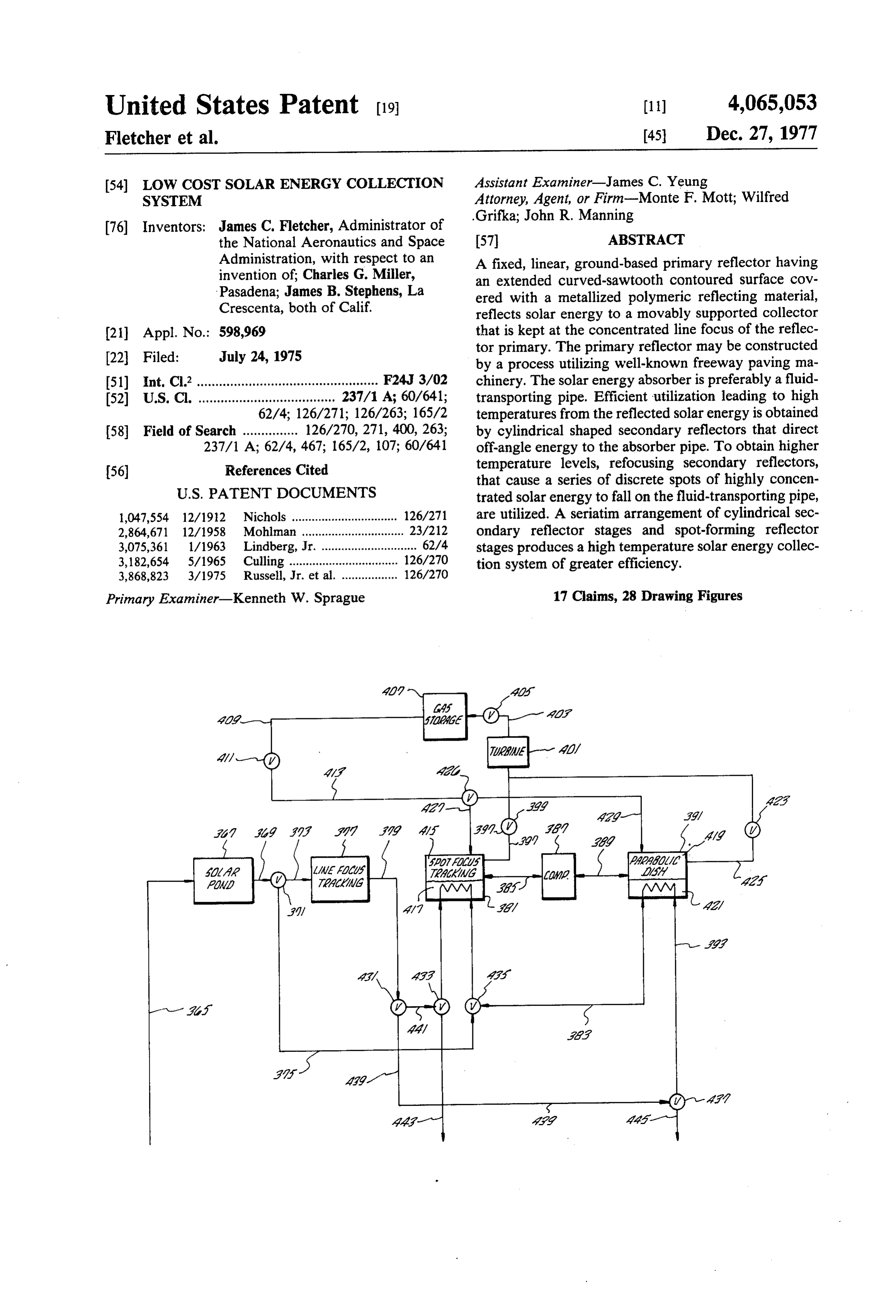
FIG, 10B and 10C are cross-sectional illustrations of then supplied, by way of interface 18 to a spot-forming other embodiments of the secondary reflectors of the focus secondary reflector tracking system 20, of the present invention; type more fully described hereinafter. The spot-forming FIG. 11 is a cross-sectional illustration of a two-di focus tracking system 20 of the type described herein mensional secondary reflector; 5 would raise the temperature of the 600 F received FIG. 12 is a cross-sectional illustration of a two-di water to approximately 800' F. The 800 F fluid may be mensional secondary reflector utilizing retroreflector raised to even higher temperatures by a three-dimen means; sional tracking parabolic dish system 24, such as is well FIG. 13 is a perspective illustration of a refocusing known in the art. The parabolic dish system 24 receives secondary reflector of the present invention; 10 the 800 F fluid over interface 22 and raises its tempera FIG. 14 is a perspective illustration of an alternate ture to approximately 1300 F. This 1300 F super embodiment of a refocusing secondary reflector of the heated fluid may then be supplied by way of interface 26 present invention; to generator equipment for use in the generation of FIG. 15 is a cross-sectional view of an alternate em electricity.
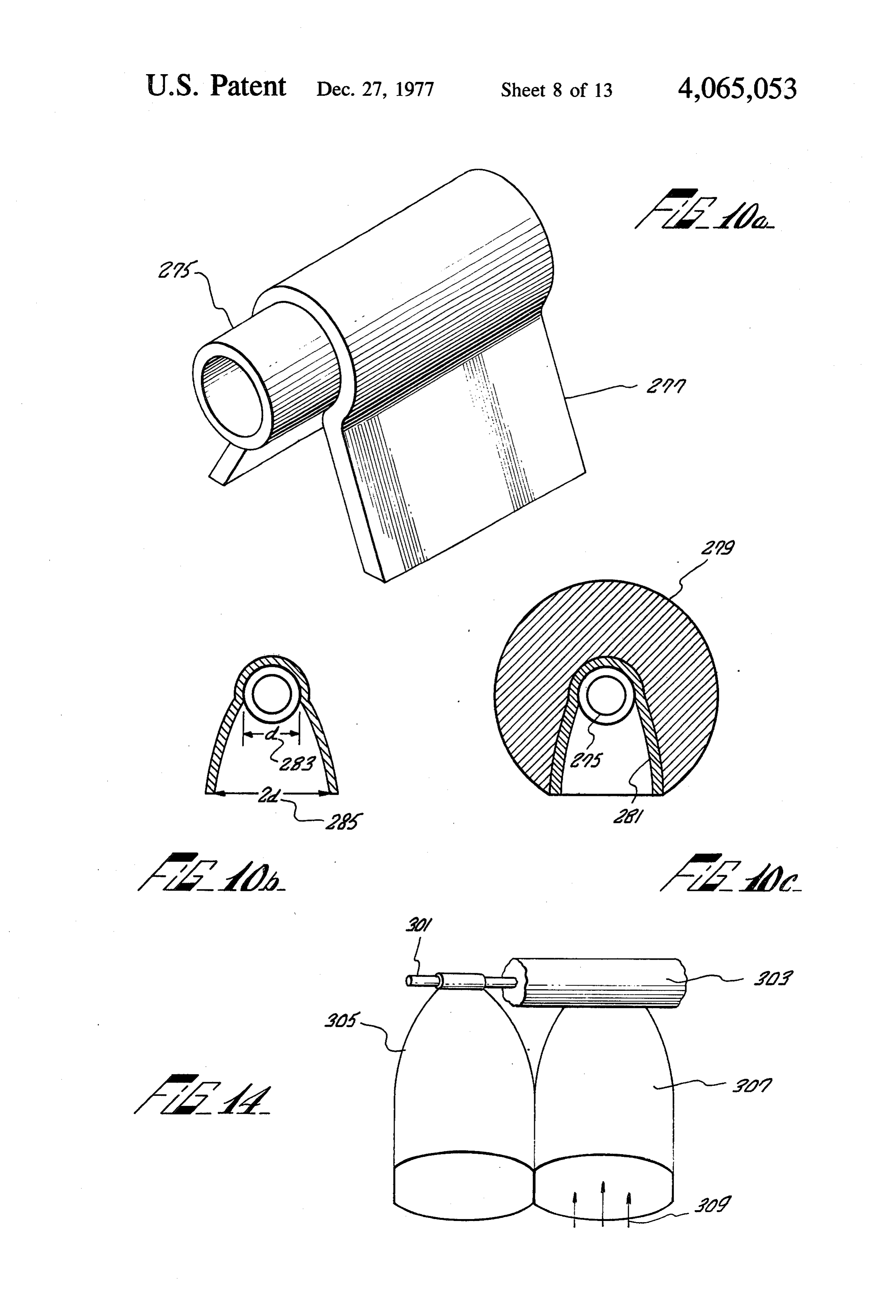
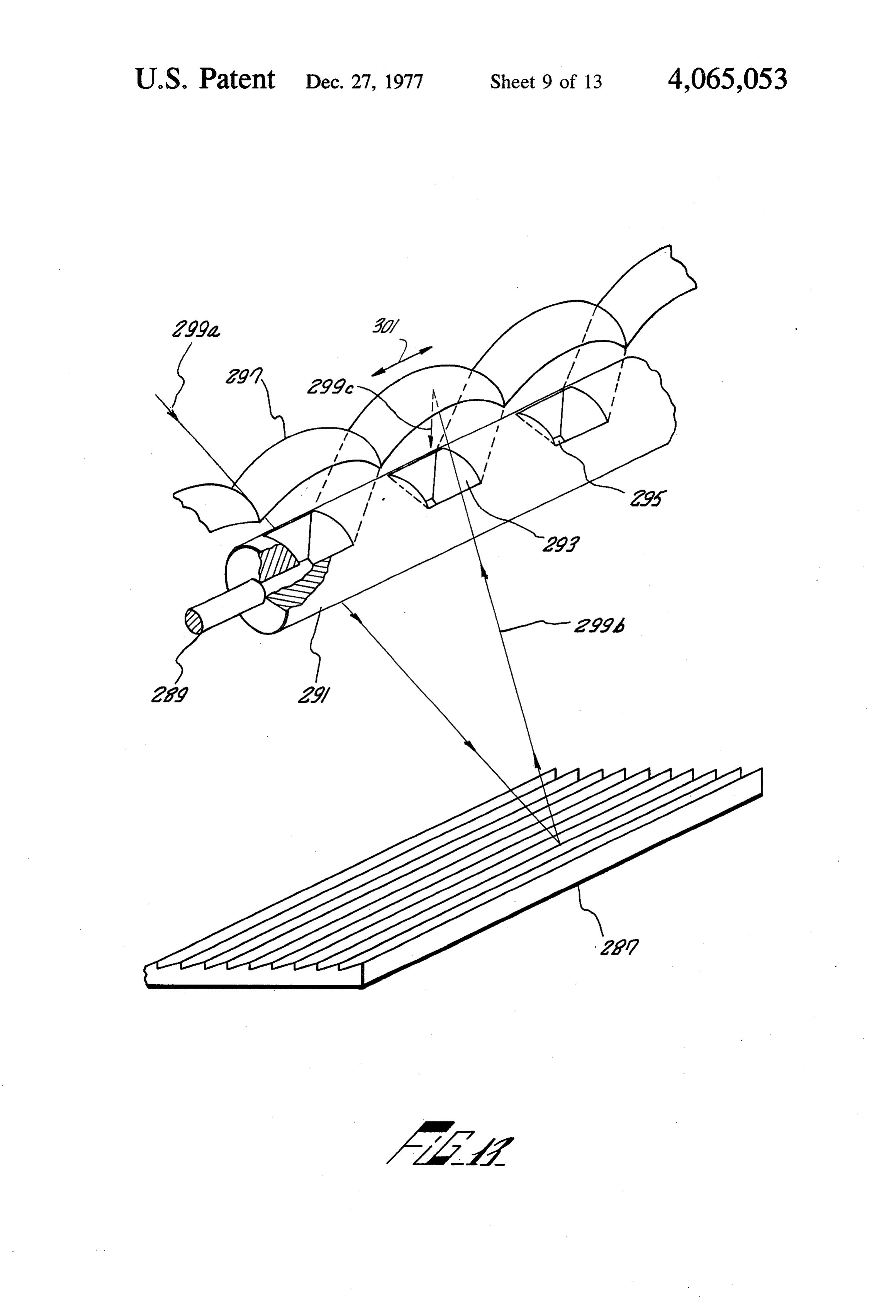
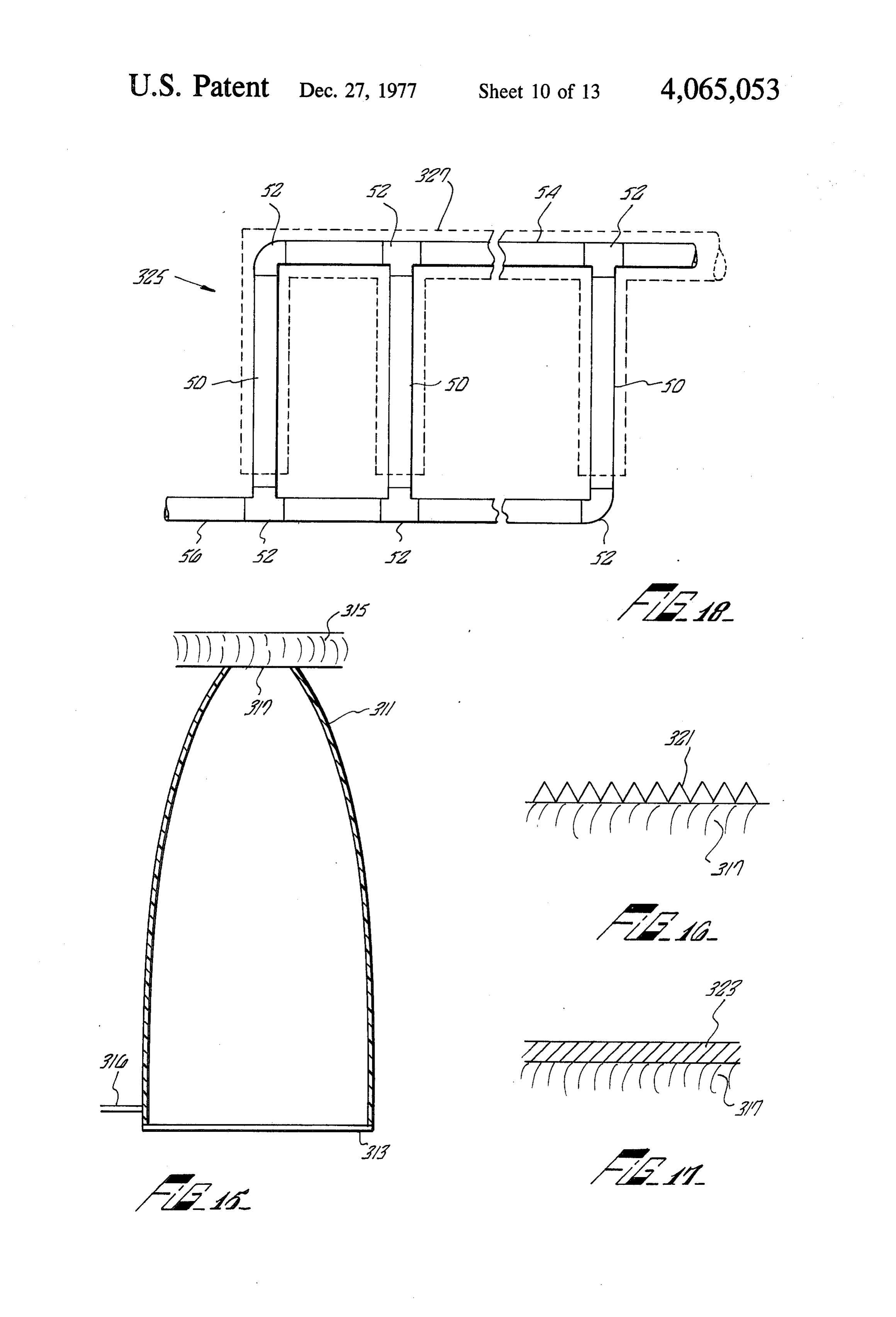
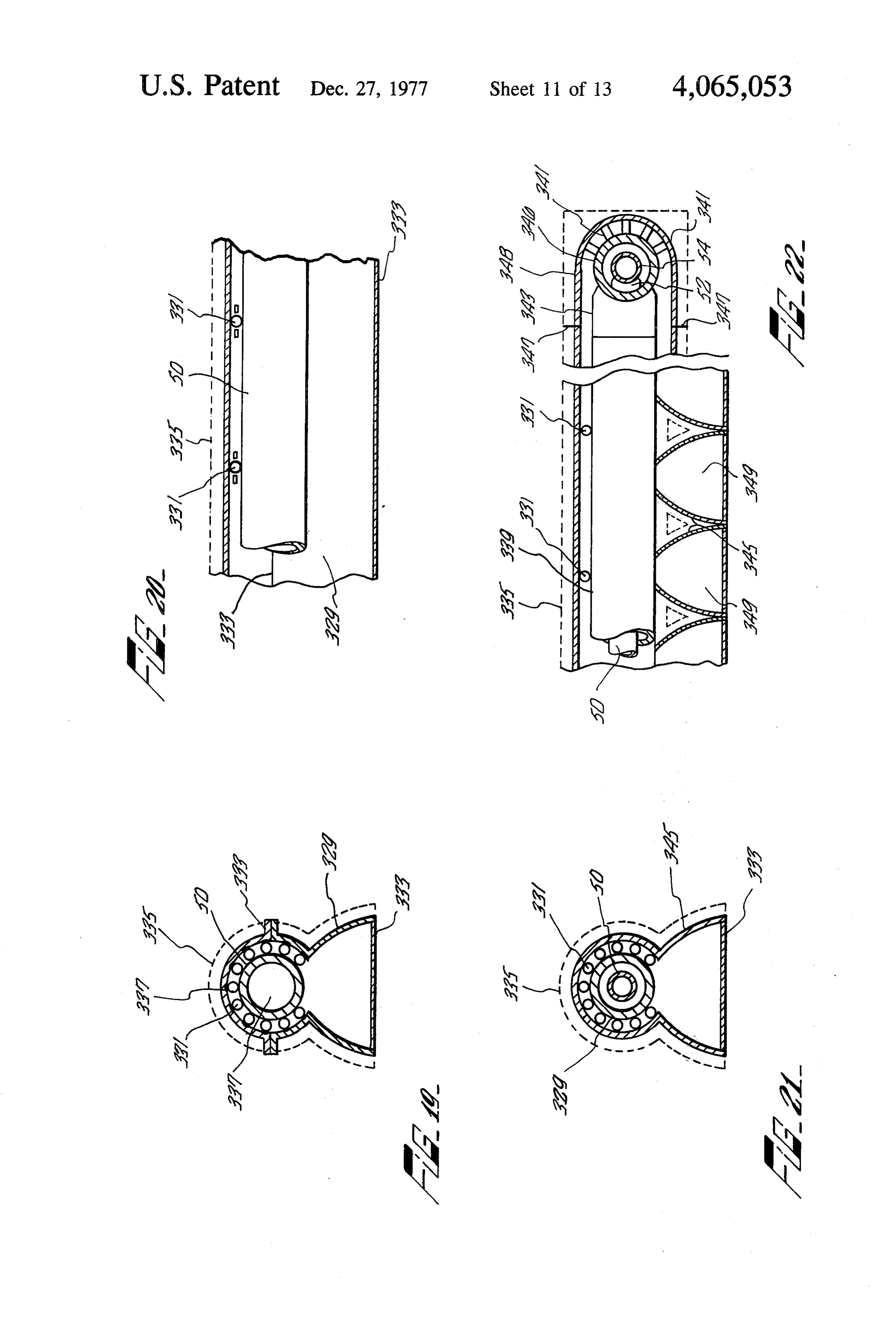
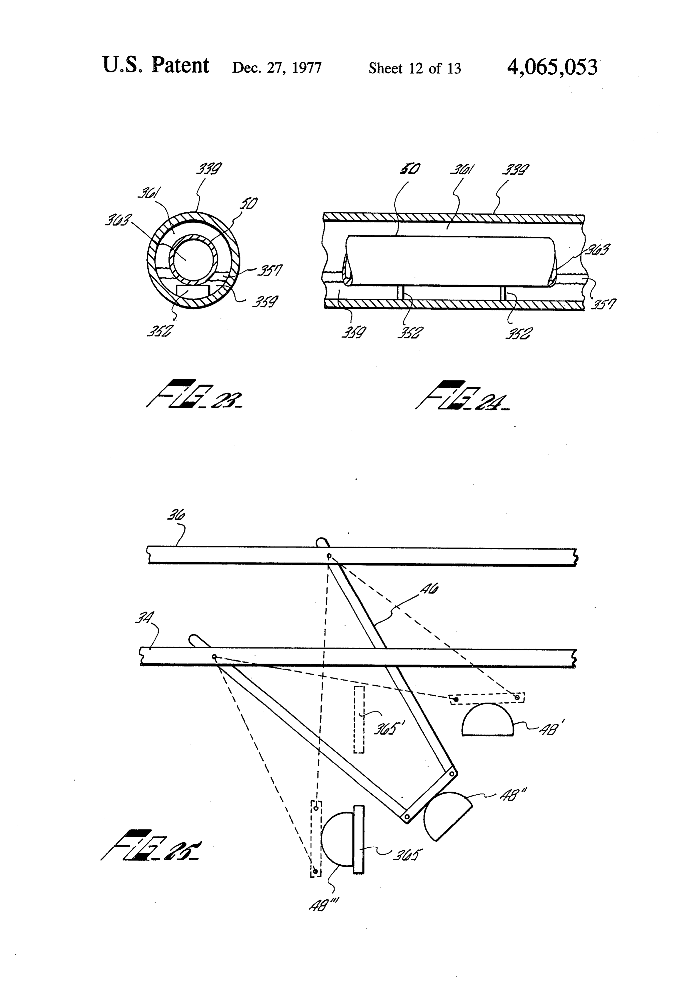
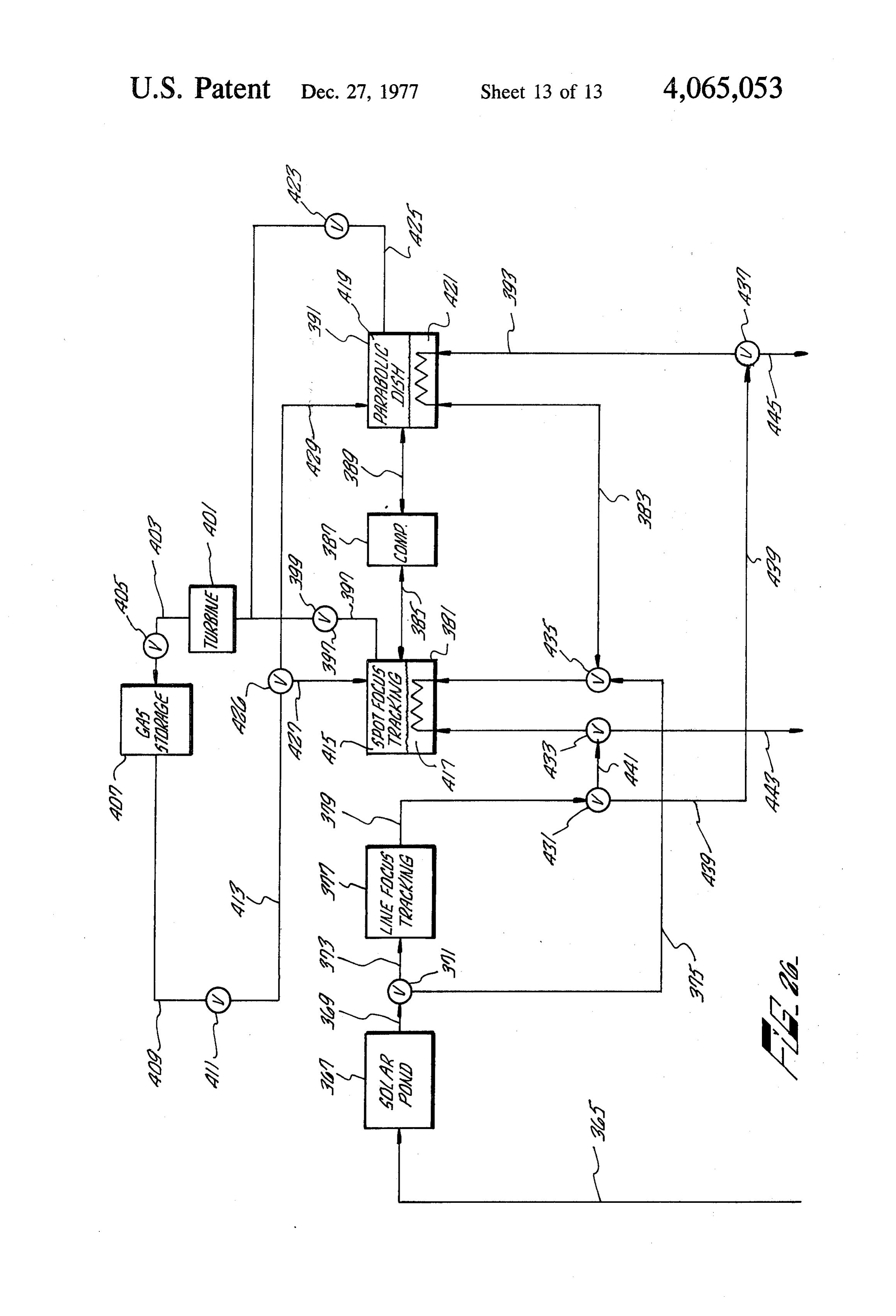
bodiment of a secondary reflector; 15 One embodiment of a tracking solar energy collec FIG. 16 is a diagrammatic illustration of a surface tion system according to the present invention is illus treatment to be used with the secondary reflector of trated in FIG. 2. The ground-based reflector 11 can be FIG. 15; made up of a plurality of identical sections 13, 15, each FIG. 17 is a diagrammatic illustration of a surface section having its own fluid-carrying vessel 87, 89, re treatment to be used with the secondary reflector of 20 spectively, for collecting the solar energy reflected FIG. 15; from the respective modular surfaces 13, 15. The width FIG. 18 is a top plan illustration of the piping net of each modular section is preferably within the capabil work used with the solar energy collection system ity of present day concrete road laying machinery. shown of FIG. 3; The sawtooth segments 25, 23, 17, 21, 22, 27, and 29 FIG. 19 is an end view section of one embodiment of 25 will make up one module 13 that can be laid by a pro an absorber pipe used in the network of FIG. 18; cess that utilizes standard highway construction or air FIG. 20 is front view section, partially broken away strip construction methods. One example of how the of the absorber pipe of FIG. 19; primary reflector modules may be formed follows. A FIG. 21 is an end view section of another embodi sifter mechanism mounted on wheels having a width ment of an absorber pipe used in the network of FIG. 30 equal to or slightly greater than the width of a primary 18; reflector module is utilized. This sifter mechanism may FIG.22 is a front view section, partially broken away have the following structure. A sifter body is divided of the absorber pipe of FIG. 21; into multiple segments, each segment utilizing a rotary FIG. 23 is an end view partial section of the absorber screen type mechanism for accepting a different particle pipe of FIG. 21 illustrating internal structural detail; 35 size. Conveniently, four segments of the following par FIG. 24 is a front view section, partially broken ticle grades may be used: rocks, coarse, medium and away, illustrating the internal structural details of the fine. The aggregate containing all these grades of parti absorber pipe of FIG. 23; cles is supplied to the sifter by a conveyor mechanism, FIG. 25 is a schematic illustration of the laterally the aggregate being inserted at the "fine” end of the movable supporting structure of FIG. 3; 40 sifter. The entire sifter mechanism moves in a direction FIG. 26 is a block diagram of an alternate embodi whereby its coarse segment is always in the front. Con ment of a staged solar energy collection system utilizing sequently the rocks or very large particles are laid down the solar energy collection system of FIG. 3 and its first, then the coarse particles, then the medium parti components as illustrated in FIGS. 18, 19, 20, 21, 22, 23, cles, and then the fine particles. 24, and 25. 45 This aggregate material may be the in-situ soil. Or, if
DESCRIPTION OF THE PREFERRED
the in-situ soil is unsuitable, suitable material may be brought in. As the aggregate is being delivered to the - EMBODIMENTS sifter a binder material such as cement is mixed in with A cost-effective solar energy collection system for it. Consequently all the various graded particles will be use with steam driven generator equipment for produc- 50 associated with the binder. As each graded particulate is ing electric power is illustrated in FIG. 1 as consisting ejected from the sifter, it is sprayed with water. of various temperature stages, each temperature stage The moistened particulate of each graded layer is comprising structure that is most efficient at that tem partially shaped to the desired contour of the primary perature range. The first temperature stage 12 of the reflector by a screed attached to the moving sifting system is preferably a solar pond. Solar ponds are well 55 mechanism for each. A plurality of pipes 62 in FIG. 2, known. An example of a superior solar pond can be having orifices therein, are preferably laid into the mul found in copending patent application U.S. Ser. No. ti-layer substrate thus formed in the medium or fine 590,975 filed on June 27, 1975 for Solar Pond by layers.
Charles G. Miller and James B. Stephens. The function The multi-layered substrate having binder material of the solar pond is to raise the temperature of cold 60 throughout is finished to the desired sawtooth seg (40-70 F) water to a temperature of 200" F. By any mented cross-section by a roller mechanism that prefer well known and convenient means, the 200 F water is ably has the following structure. A roller having the transmitted over interconnect 14 to a line-focus secon inverse curvature of the desired profile and being the dary reflector tracking system 16, of the type more fully width of a primary reflector module travels along the described herein. 6S graded aggregate substrate in front of a sled having the The line-focus secondary reflector tracking system 16 same contour, as the roller. The sled has mounted would raise the temperature of the received 200' F thereon acoustic vibrators that operate at high fre water to approximately 600 F. This 600 F steam is quency to provide a very smooth surface to the saw
Page 17
tooth segmented primary reflector. The depth of the of curvature of the troughs depend upon the width of various segmented steps with varying radii of curva each module. The depth depends on the slump factor tures 25, 23, 17, 21, 22, 27, and 29 is determined mainly limitations of the stabilized soil or concrete used to form by the slump factor of the thus stabilized soil during its the primary reflector profile. This will also be more curing process. fully explained hereinafter.
An aluminized mylar sheeting material, 0.00025 An alternate and preferred support structure for high inches thick, or equivalent reflective material is laid temperature reflector sections according to the instant over the slip-formed profile. The reflecting material is invention comprises the use of a single rigid assembly held down by a slight vacuum created at the surface of for the absorber pipes, and utilizing inlet and outlet the reflector profile by drawing a vacuum on the pipes 10 manifolds, thereby eliminating the requirement of high laid therein. Since concrete is a porous substance, draw pressure and rotary slip-joints, as will be seen hereinaf ing a vacuum on the pipes within the concrete will ter.
create a low pressure region at the surface of the con A variation of the stanchions of the type shown in crete. This will hold the reflective film material in place FIG. 2, is shown in FIG. 3. A plurality of upright sup without the necessity of glue or some other such fasten 15 port members 28, 30 are provided for each primary ing means. Holding the reflector covering in place by a reflector module. Each upright support member sup vacuum also facilitates rapid replacement of torn or ports at least a pair of transverse support members 34, dirty reflector material. A vacuum level which varies in 36, 38, 40, 42, and 44. Transverse support members 34, intensity suitable to the prevailing wind velocity is pre 38, and 42 are located at a first level. Transverse support ferred. An inexpensive method of producing the vac 20 members 36, 40, and 44 are located at a second higher uum is by steam ejection, using the steam supplied by level.
the system. Four-bar linkages 46 are suspended from the trans Each segmented module of the reflector, such as verse support members at appropriate locations. Each module 13 has a flat section 31 which can provide ac four-bar linkage is moved by actuating devices 32 as cess to the curved reflector segments for maintenance 25 described hereinabove. Each four-bar linkage fastens to and inspection purposes, using a gantry-type vehicle. and supports a secondary reflector mechanism 48 that One type of support structure that may be used com swings in an arc and pivots about its central axis as the prises a plurality of stanchions 51, 53, 55 equidistantly four-bar linkages are moved. Exactly how this is ac spaced along a line parallel to the longitudinal axis of complished will be more fully explained hereinafter. each reflector module of the reflector 11. The stan 30 Each secondary reflector mechanism 48 supports an chions 51, 53, 55, for example have a four-bar linkage absorber pipe 50 that carries a heat-absorbing fluid. The 75, 77, 79, respectively, attached thereto which sup exact structure of the absorber pipe will be more fully ports the fluid-bearing pipe 87. A hydraulic or electrical explained hereinafter. Each absorber pipe 50 in each actuating device of well-known construction 63, 65, 67 secondary reflector 48 is connected to the other pipes is respectively located on the stanchions 51, 53, 55 for 35 50 by an inlet manifold 54 and an outlet manifold 56, for moving the four-bar linkages 75, 77, 79 in synchronism. supplying a cool heat-absorbing fluid and removing the This synchronous movement of the linkage causes the hot heat-absorbing fluid, respectively. The absorber fluid-bearing pipe collector 87 to be transversely shifted pipes are connected to the manifolds by high-pressure in an area relative to the reflecting module 13. The joints 52, thereby forming a rigid network that moves in movement of the pipe collector can be controlled either 40 unison as the four-bar linkages are caused to move. by a programmed source correlated to stored data relat It is well known in the art, that a parabolic reflecting ing to the apparent sun movement in the area, or alter trough focuses received parallel light rays, (that arrive natively by sun sensing and following systems similar to in a direction such that a plane perpendicular to the that used for altitude control on spacecraft. directrix sheet contains the light rays in question,) into Every other module of the reflector 11 is similarly 45 a line focus along a line parallel to the vertex line and constructed. Each module, such as module 15, for ex passing through the axis. If the received light rays, ample, has a flat walkway portion 33 in which the plu arriving parallel at a parabolic trough, arrive in such a rality of stanchions 57, 59 and 61 are placed. These direction that they make an angle with the above-men stanchions support respective four-bar linkages 81, 83 tioned plane perpendicular to the directrix sheet, the and 85. Each bar linkage supports a portion of the fluid 50 line focus suffers from coma and the focus becomes carrying pipe 89 which is moved transversely in an arc diffuse. It is for this reason that parabolic trough reflec by actuation of motive means 69, 71 and 73 respectively tors must be guided so that they always face the incom connected to the bar linkage devices. The cylindrical ing sunlight squarely.
segments 40, 41, 35, 37, 36, 43, and 45 of the reflector It is possible to achieve many of the results of the module 15 may have the same radius of curvature as the 55 tracking parabolic trough, with a non-tracking reflect segments 25, 23, 17, 21, 22, 27 and 29, respectively of ing trough if the cross-section is made to be circular. module 13. Cylindrical reflecting surfaces of circular cross section These optimum width modules of the reflector sur approximate the parallel line focusing action of an opti face 11 may be laid side by side, in the manner illus mally-positioned parabolic cylinder, if only small seg trated in FIG. 2, for any desired distance. The length of 60 ments of the circular cylinder surfaces are utilized. In each reflective module, along the longitudinal axis, may coming parallel light is brought to a substantial line also be any length desired. It is envisioned that a reflec focus for most angles of approach of the sunlight to the tor surface a mile square could be utilized in a staged circular trough, albeit the location of the line focus Solar energy collection system used to generate suffi varies with the angle of approach of the sunlight. cient heat for a 100 megawatt power plant. 65 FIG. 4 illustrates a circular trough 92 receiving a The height of the stanchions for each reflector mod plurality of differently angled parallel light beams. If ule depend upon the radius of curvature of the troughs, only a small segment of the circular trough 92 is consid as will be more fully explained hereinafter. The radius ered, such as segment 94, for example, parallel light rays
Page 18
97A, 95A, 93A impinging upon the segment are re chosen so that the distance from their surface to the flected at the surface of the radius of curvature with an chosen focal surface 131 is equal to half of their radius angle of incidence that equals the angle of reflection. As of curvature. Segments 133, as shown in FIG. 5 can be a consequence, rays 93A, 95A and 97A are reflected as seen as having a radius of curvature 135, termed ri rays 93B, 95B and 97B. These rays intersect at a point extending from a center of curvature 147. 105 lying on the focal surface 109. Rays 99A, 101A and The location of point 147 is chosen so that the dis 103A of the cylindrical segment 94 are reflected as rays tance from surface 133 to point 147 is twice the distance 101B 103B and 99B that intersect at a point 107 on the from surface 133 to the selected focal surface 131. For focal surface 109. Other skewed light rays, such as rays this reason, the focal surface of segments 133 will be 116A for example would impinge upon the cylindrical 10 located on a cylinder with its center at point 147 and surface 92 and be reflected in a direction 116B, and so having a radius ()r. From the geometry, the focal on. The focal point 105 for parallel lines 95A, 97A, 93A, surface of segments 133 will be almost exactly coinci and the focal point 107 for parallel lines 101A, 103A and dent with focal surface 131, the focal surface for seg 99A turn into focal lines that run parallel to the longitu ment 125. Therefore, an absorber pipe travelling along dinal axis of the cylindrical trough when sheets of light 15 focal surface 131 and receiving reflected energy from rays parallel to 99A, 101A and 103A but extending into segment 125, will, at the same location, receive energy and out of the paper are considered. The focal surface reflected from segments 133.
109 therefore becomes a cylindrical focal trough. In a similar fashion, segments 139 are given a radius Because a shallow reflecting surface is desired from of curvature r extending from a point 149. The loca the standpoint of economy in construction and mainte 20 tion of point 149 is chosen so that the distance from nance, the maximum height 111 to which any reflecting segment surface 139 to the earlier-selected focal surface surface may peak should not exceed approximately 12 131. Therefore, the focal surface of segments 139 will be inches. This problem can be overcome by segmenting located on a cylinder having its center at point 149 and the cylindrical surface 92 into a sawtooth-like reflecting a radius of ()r. Thus, the focal surface of segments 139 surface. Thus, for example, segment 119 is the segment 25 will be almost exactly coincident with focal surface 131, 117 of the cylindrical surface 92 brought down to lie on the focal surface of segments 126. a common plane with segment 94. Likewise, segment By choosing the radius of curvature of the various 115 is segment 113 of the cylindrical surface 92 brought segments in the trough reflecting surface 123 in this down to lie on the same common plane. These segments manner, a reflecting surface that effectively functions all have a common height 111. 30 like the deep trough 117 of FIG. 4, but is actually This segmented reflecting surface, however, will not shaped as shown at 123 in FIG. 5, is obtained. The function to focus parallel lines into a line focus on the reflector-concentrator cross-sectional profile 123 illus surface of focal trough 109. Although the radius of trated in FIG. 5 can be slip-formed according to the curvature of the various segments are the same as the process above described. Rather than slip-forming the radius of curvature of the cylindrical trough 92, the 35 reflector surface to have straight edges 128, sloping distance from the center of curvature of the cylindrical edges 130 at an obtuse angle are formed. The reason for trough 92 varies for each segment. As a consequence, interleaving the segments in this manner is that the area ray 116A, for example, will be reflected from surface 132 within each valley between the imaginary straight - segment 115 along reflected light beam 118B. Light edge 128 and the real sloped edge 130 is not effective as beam 116A travels an extra distance 118A before it 40 a reflecting surface because of shading by the upper strikes a reflecting surface 115. The focal point for all corner of edge 128. As will be more fully explained parallel light rays striking reflective surface 115 will lie hereinafter, by choosing the slope of edges 130 care at point 122 which is on a different focal surface of fully, light rays striking those edges can be reflected to curvature 120 than the focal surface 109 of cylindrical the line focus of an adjacent collector. surface 92. Each segmented radius of curvature such as 45 The orientation of the longitudinal axis of the seg 119 for example may well have a different focal surface. mented trough reflector surface will determine the ex In order to provide a segmented one-dimensional tent of movement required by the collector pipe along linear reflecting element that is within the range of 4 to the focal surface, in order to track the movement of the 12 inches in height, the radius of curvature of the vari sun diurnally and seasonally. An east-west longitudinal ous segments must be chosen so that no matter which 50 axis orientation is the preferred orientation for the rea segment of the equivalent flattened reflective surface son that a minimum of collector movement will be 119, 94 and 115, for example, is impinged upon by paral required. FIG. 6 illustrates the various positions that the lel light rays, these light rays will intersect in the surface collector must take during various times of the day and of a common focal surface. FIG. 5 illustrates how the throughout the year, in order to be at the focal line of radius of curvatures for the various segments of the 55 the solar energy reflected from the surface 151, at all reflector 123 are determined. The largest segment 125 times. The various segments of the reflector 151 have of the reflecting profile 123 is chosen to have a radius of radii of curvature that will cause a substantial part of the curvature (r) 127 that, for example, is 10 to 20 feet, this parallel light impinging on most parts of the reflector distance being a practical distance for the height of the surface to be reflected to a common point on arc 155. stanchions. Conceivably, higher stanchions feet goes up 60 The longitudinal axis of the reflecting surface 151 is considerably. assumed to be oriented in the east-west directon so that Having determined the radius of curvature for the the troughs of the reflecting surface are parallel with main segment from cylindrical center of curvature 145 the east-west direction. Broken line 153 represents the to be approximately 20 feet, the focal surface 131 is local vertical axis, shown here for purposes of refer located 10 feet, from the surface of segment 125. This 65 ence. For an example relating to a location at latitude focal surface distance is equal to half the radius of cur 34' N, a light ray 157A, at an angle of 11 to the local vature ()ra. The radii of curvature of the other seg vertical, depicts the angle of incidence of solar energy ments such as 133 and 139, for example, must then be impinging upon the reflector surface 151 at about 12
Page 19
noon on June 21, i.e., the summer solstice. This light is the equinox dates of March and September, however, reflected by surface 151 as a light beam 157B, and inter the collector pipe is substantially stationary at point 172. sects the focal arc 155 at point 165. As the afternoon By not requiring large transversal movements on a daily wears on, the angle with the local vertical increases, basis, the drive mechanism for moving the collector causing the reflected light beam 157B to move toward pipe along the focal arc 155 is considerably simplified. point 161 on the focal arc 155. At approximately 3:00 FIG. 7 illustrates one embodiment for suspending the P.M., the reflected light rays 157B are intersecting the high pressure steel, a heat-absorbing, fluid-bearing col focal arc 155 at point 161. At 9:00 A.M. that same day, lector pipes that are moved to always be at the focal line the light rays 157A impinging on surface 151 were re of the reflected sun's rays. The pipes 201,217 preferably flected to cross the focal arc 155 at the same point 161. 10 carry water or other fluid that is heated by the reflected Thus, in the morning, these reflected rays will move solar energy from the reflecting surface 199. As was from point 161 on the focal arc 155 towards point 165, explained earlier, the fluid-bearing pipes 201 and 217 and back toward point 161 in the afternoon. must move along the focal arcs 215, 233, respectively, in The light ray 159A depicts the solar energy from a order to track the sun's movements.
noon time sun on December 21. This energy is reflected 5 There exists for every set of distance and size rela by surface 151 as light rays 159B to intersect the focal tionships between the modules that make up the solar arc 155 at point 179. At about 3:00 P.M., the reflected collector, an obtuse angle for the edges 130 of the seg rays 159B are intersecting the focal arc 155 at point 183. ments of the primary reflector 199 that is most effective At 9:00 A.M. of that same day, the rising sun causes the in reflecting the incident light rays to an adjacent col reflected beam 159B to intersect the focal arc 155 at 20 lector. For example, an incident light ray 206A hitting point 183. Thus, the sun's movement causes the re segment surface 132 is reflected as ray206B to collector flected rays to start at point 183, gradually move to 201. Because of the obtuse angle of slope of edge 130, point 179, at noon, reverse itself and go back to point the entire surface 132 of that segment is an effective 183. reflector. Light rays, such as ray 208A incident on edge Segment 193 of the focal arc 155 depicts the swing of 25 surface 130 are reflected as rays 208B to the collector the reflected sun's rays during the month of January. At217 for the adjacent module. Likewise collector 201 will receive some light rays reflected from the edge about 9:00 A.M., the reflected light rays cross the focal arc at point 181. During the morning, they move surface 130 of its adjacent module. toward point 177 where they cross at noon time. In the One parallel line of stanchions would be required for afternoon they move back toward 181 where they cross 30 each transversely movable collector pipe. The heat at 3:00 P.M. Segment 191 of focal arc 155 depicts the absorbing pipe 201 is connected to a vertical intake pipe movement of the reflected sun's rays during the month member 205 and a vertical outlet pipe member 203. of February. Intersection 173 is the noon time intersec Water (preferably treated or distilled in liquid, vapor or tion and intersection 195 being the +3 hours from noon steam form) is supplied to vertical pipe member 205 intersection point. Intersection point 172 of focal arc 35 from pipe 209 through a high-pressure slip joint 213. 155 represents the intersection of the reflected light rays Steam from the vertical pipe member 203 is supplied to during the month of March. There is minimal move pipe 207 through a high-pressure slip joint 211. The ment of the reflected light rays at the equinox date assembly consisting of pipes 205, 201, and 203 can be because the sunrises directly in the east and sets directly seen to make up a trapeze that pivots at slipjoints 213 in the west on this date. The segment 189 of the focal 40 and 211 to swing in the focal arc 215. In order for the radius 155 represents the movement required during the pipe 201 to swing along this focal arc 215 the distance month of April, intersection point 171 being the noon from the slipjoints to the pipe must be equal to half the time intersection point. Intersection point 169 is the +3 focal radius of the basic segment in the reflector surface hours from noon intersection point. Segment 187 of 199.
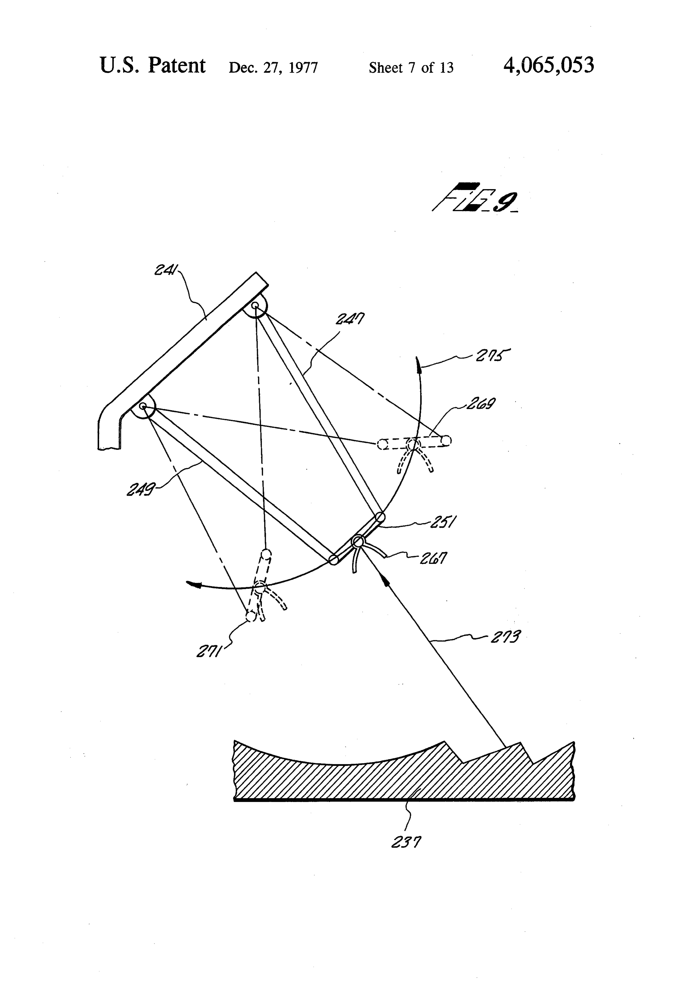
focal arc 155 is the movement required during the 45 As was illustrated in FIG. 2 another parallel line of month of May, intersection point 167 being the noon stanchions may support another fluid-bearing pipe time intersection point. Intersection point 163 is the E3 member 217 suspended to swing along the focal arc 233. hours from noon intersection point. As already noted, The vertical inlet pipe 219, the vertical 221 and the segment 185 of the focal arc 155 is the movement re heat-absorbing pipe 217 again form a trapeze that quired for the month of June, intersection 165 being the 50 swings about the slipjoints 229 and 231 that connect the noon intersection point and intersection point 161 being inlet pipe 225 and the outlet pipe 227 to the trapeze the +3 hours from noon intersection point. assembly. The length of the heat-absorbing pipe assem For the month of July, the reflected sun's rays again bly is determined by the length of each modular section move along segment 187 of focal arc 155 as they did in of the primary reflecting surface. The number of heat May. In August the reflected sun's rays move along 55 absorbing pipes utilized is determined by the number of segment 189 of focal arc 155 as they did in April. In modules forming the entire primary reflecting surface. September the sun again rises directly in the east and The structure for supporting the heat-absorbing pipe sets directly west as it did in March. In October the assembly of FIG. 7, and transversely moving it along reflected sun's rays again traverse segment 191 of focal the focal arc is illustrated in FIG.8. A stanchion having arc 155 as it did in February. In November the reflected an upright member 239 and a slanting member 241 sup sun's rays again traverse segment 193 of focal arc 155 as ports a bar linkage arrangement consisting of linkage it did in January. 247, 249 and 251. These linkages are connected together In order to track the sun's movements diurnally and by pivot joints 263,261 and are connected to the stan seasonally, the collector must traverse the focal arc 155 chion member 241 by pivot joints 257, 255. The heat as the sun moves in the sky. As can be seen from FIG. absorbing pipe 253 is fastened to the bar linkage 251. A 5, however, the movement of the collector during each secondary reflector 265 may be placed over the pipe. A day is quite small. Thus, for example, during December hydraulic or electric, or other suitable motive means the collector need only move within segment 185. At 243 having a transversely movable arm 245 is pivotally
Page 20
connected at a point 259 on bar linkage member 249. that may be magnesia or some such other high tempera The transverse movement of the arm 245, as directed by ture insulation. The open end and inside of the field motive means 243, causes the entire linkage assembly to collector are left exposed, to receive the reflected solar shift the heat-absorbing pipe 253 along the focal arc of energy rays.
the primary reflecting surface 237. 5 The system described so far has a relatively high FIG. 9 more clearly illustrates the movement of the concentration ratio since it is a tracking trough system bar linkage mechanism to cause the collector to swing and can deliver high heat fluxes to the absorber pipe. As along the focal arc 275. During the winter months the the temperature of the fluid in the pipe rises, it pro bar linkage of the trapeze assembly is located in the gresses from the inlet end toward the outlet end, the general area of bar link 269 of focal arc 275. The oscilla 10 protection afforded by the insulating material around tory motion of the bar linkage will be within the one the secondary reflector shown in FIG. 10C becomes segment, as described in connection with FIG. 4. Dur inadequate. This is so, because of radiant heat loss and ing the equinox months, or March and September, the convective heat loss through the unprotected open end trapeze assembly, consisting of bar links 249, 247, and of the secondary reflector becomes unacceptably large 251 are located as shown in solid lines. Very little oscil 15 for high temperature operation. latory motion is necessary during these months. The When dealing with higher temperature sections of the secondary reflector 267 is angled to receive the re absorber pipe, that is those sections of pipe further from flected solar energy 273 from the primary reflecting the inlet end and closer to the outlet end, a modification surface 237. During the summer months the bar linkage of the secondary reflector becomes economically justi member of the linkage assembly is located in the general 20 fied, and is shown in FIG. 12. The secondary reflector area of link 271 on the radial arc 275. The bar linkage of FIG. 12 is compared with the secondary reflector of will oscillate along the radial arc 275 within the seg F.G. 11 which shows the features from which the sec ments described in connection with FIG. 4. It can be ondary reflector of FIG. 12 evolved. seen that although the swings required of the bar link FIG. 11, shows a more detailed version of a sophisti age from the winter to summer months is great, the 25 cated curved-side secondary reflector than that shown daily swing of this linkage is minimal. Thereby, tracking in FIGS. 10B and 10C. This secondary reflector func the daily movement of the sun's image requires minimal tions to focus light entering its mouth 284 having a size movement of the trapeze mechanism. As can be seen dwithin its acceptance angle 280 onto the dalength 282 this trapeze tracking mechanism is relatively small and of the collector. This two-dimensional reflector is made therefore allows low cost, low maintenance and mini 30 up of two parabolically curved sides 288 and 290, mal windage problems. chosen so their respective focal points 294 and 292 fall The reflecting surface of the present invention is not on the corner of the opposite parabolic side. optically perfect. Even if it were, the environmental The relationship of the distanced across the mouth condition in which it must operate would detract from 284 to the distanced at the collector 282 is its optical reflective characteristics in time. This situa 35 tion will cause the reflected solar energy to scatter somewhat rather than being reflected as a clear, sharp energy beam. In order to gather in as much of this scat for the chosen angular acceptance of 45. tered, reflected energy as possible, a two-dimensional Thus, if the distance dis chosen to be approximately secondary reflector 277 such as illustrated in FIG. 10A four inches, the diameter of the collector pipe, the dis is placed around the heat-absorbing collector pipe 275. tanced across the mouth would be approximately 5.6 The secondary reflector 277 is shown as being substan inches. The relationship between the two distances de tially a U-shaped member having straight or angled and d and the L length 286 of the two-dimensional legs. The closed end of the U-shaped member of the reflector is:
secondary reflector 277 is form-fitted around the heat 45 absorbing pipe 275. Any solar energy rays falling within L = (d. -- d) cot 45 the open mouth of the secondary reflector 277 will be substantially directed towards the pipe 275. The pre For d = 5.6 inches and dA = 4 inches, L is approxi ferred material out of which the secondary reflector 277 mately 4.8 inches.
is made is aluminum, or any equivalent thereof. 50 The secondary reflector of FIGS. 10 and 11 accept FIG. 10B is a cross-sectional view of an alternate solar energy through their whole acceptance angle, and embodiment for the secondary reflector in which the also allow the absorber pipe to emit energy in the form angled legs 282 and 284 of the reflector are curved, of infrared rays through the same acceptance angle. rather than being straight. The distance between the In order to decrease the radiation of heat from the angled legs 284 and 282 at the open end 285 of the 55 absorber pipe body a two-dimensional secondary reflec reflector is preferably twice the diameter of the heat tor of the type illustrated in FIG. 12 may be used. This absorbing pipe at the closed end 283 of the reflector. It constitutes an improvement. This additional complexity is conceived that a collector pipe diameter of four is justified for those sections of the absorber pipe where inches would be utilized. Therefore, the distance be the fluid therein is at a relatively high temperature so tween the curved leg members 284 and 282 would be 8 60 that an appreciable amount of infrared energy will be inches. radiated away if the simple secondary reflector of FIG. In order to retard reradiation and convection heat 11 were used. The secondary reflector of FIG. 12 func loss, as a first step for use on the low temperature sec tions to prevent a significant fraction of the re-emitted tion, the outside and back of the secondary reflector and infrared radiation from escaping the reflector. The the heat-absorbing pipe may be covered with an insulat 65 trapped infrared radiation is returned to the absorber ing material, as shown in FIG. 10C. The heat-absorbing pipe by the shelves 304.
pipe 275 carrying the secondary reflector 281 is shown The overall curvature of the two sides 296 and 298 of to be completely covered with insulating material 279 the secondary reflector of FIG. 12 follow the parabolic
Page 21
curvatures 290,288 of the secondary reflector shown in ing, nickel-oxides or chemical coatings such as calcium FIG. 11. The focal point of parabolic curvature 296 is fluorides, for example, have a tendency to deteriorate point 300. The focal point of parabolic curvature 298 is with age. For this reason, it becomes difficult and costly point 302. The shelf-type indentations 304 in the sides to maintain a high absorptivity/emissivity ratio in con 296,298 of the two-dimensional reflector act to reduce 5 ventional linear pipe collecting systems over a substan the radiation of heat from the collector. The shelves 304 tial period of time using such coatings. As a conse act as retroreflectors by being covered with retroreflec quence of the consistently high a/e, ratio obtainable tive material such as glass beads or being indented by with the secondary refocusing reflector of this inven cube-corner embossing. Any radiation coming from the tion, this system will provide considerably higher tem absorber pipe will have a random directionality with a 10 peratures than conventional trough systems can pro lambertian distribution. The rays that strike the shelves vide, over an extended time period. The temperatures will be reflected back to the absorber. This reduces the obtainable will approach those obtainable from a track heat loss of the absorber, thereby increasing the overall ing dish reflector.
efficiency. The compound curvature reflecting surfaces 297, A tracking solar energy collection system as de 15 shown in FIG. 13, are preferably made out of a reflect scribed above, using line-focusing secondary reflectors ing material such as aluminum which can easily be of the type shown in FIG. 11 is relatively efficient stamped out in large quantity at a very reasonable cost. within a temperature range of 200' to 400 F. A track Any convenient means may be utilized to movably ing system of this type could therefore be used as the suspend the reflecting surfaces over the heat-absorbing line-focus tracking stage 16 in the staged system of FIG. 20 pipe 289. A motive means (not shown), such as a cam 1. mechanism, is utilized to move the reflecting surface In order to obtain higher energy concentration ratios assembly 297 back and forth in the direction indicated for higher temperature results, a refocusing secondary by the arrow 301. This movement of the reflecting reflector, according to the present invention, must be assembly 297 is required to maintain the spot focus of utilized. A preferred embodiment of a refocusing secon 25 each reflector within the area of its respective recess as dary reflector is illustrated in FIG. 13 as consisting of a the sun's image changes position during the day. plurality of compound curvature reflecting segments FIG. 14 illustrates an alternate embodiment of a refo 279. Each segment has a parabolic curvature along the cusing secondary reflector. The secondary reflectors direction parallel to the heat-absorbing collector pipe 305, 307 for this embodiment consist of bell-shaped 289 and a circular curvature along a direction perpen 30 members that are suspended from the heat-absorbing dicular to the collector pipe 289. An insulating material collector pipe 301 at their closed end. The collector 291, is placed around the pipe 289. This insulating mate pipe 301 actually runs through the interior of the bell rial may be magnesia or some other suitable high-tem shaped members 305,307 at their closed ends. The bell perature insulating material. A plurality of recesses 293 shaped members have compound paraboloid curvatures having sloping sides that leave a small area 295 of the 35 therein that are chosen for the optimal refocusing of pipe exposed are formed in the insulating material and solar energy 309 entering their open mouth into a small spaced to be directly underneath each compound cur spot area on the pipe running through their closed end. vature reflecting surface 297. Solar energy rays 299A The depth of the field collectors 305,307 decrease rera reflected from the reflector surface 287 as rays 299B, diation and convection heat loss from the exposed pipe strike the compound curvature reflecting surface 297 301. These bell-shaped field collectors 305, 307 are and are focused thereby into a spot on the heat-absorb spaced as densely as possible along the heat-absorbing ing collector pipe 289. The insulating material around pipe 301 to provide a series of high intensity spot fo the pipe prevents reradiation and convection losses, cuses of solar energy on the pipe 301. To prevent con except at the relatively small exposed spots at the bot vection heat loss from the pipe itself, a high temperature tom of the recesses. The concentration of the rays 299B 45 insulating material 303 is wrapped around the pipe 301. into a spot focus on the collector pipe generates a higher Due to the generally inverted shape of the bell mem temperature than would be obtainable from a line-focus, bers, with the open mouth disposed downwardly, the and can produce temperatures in the range of 400 to hot spot on the pipe heats the air in the upper closed end 800 F. of the bell member. As a result, hot air convection cur The use of the secondary refocusing collector, such 50 rents cannot circulate, thus avoiding another potential as shown is FIG. 13, with the fixed ground-imbedded loss of heat energy from the pipe. The bell-shaped mem linear primary reflector of FIG. 2 can be viewed as bers thus, not only focus the incoming light rays into a equivalent to a dish-concentrator, since the image from spot but also diminish convection loss, and diminish any given area of the ground-imbedded reflector has reradiation loss, which effectively give a high a/e, ratio. diminished in size both longitudinally and transversely 55 It may be helpful at this point to remember that the in forming a spot. reentrant secondary reflectors already described uti Alternately, if the system is considered as a trough lized the directionality character of absorbed light (om collector system, all the collected energy enters the nidirectional when reradiated) to advantage by struc absorber pipe, as in any linear-focus system. However, tural means. For example, the linear-focusing secondary since the absorber pipe is covered with insulation, only 60 reflector of FIG. 12 utilized shelves that were retrore a small fraction, for example 1/10 of the total surface flectors to reflect reradiated energy back to the ab area, is available for loss by reradiation. The system sorber pipe. The spot-image forming refocusing secon then can be considered as equivalent to a linear-focus dary reflector of FIG. 13, likewise can be structured to trough collector system with an absorptivity/emissivity reduce the amount of reradiated energy leaving the (a/e) ratio of 10, for example. Since this high ratio of 65 structure. To enhance the reentrant capability of the effective a/e is achieved geometrically and not be sur three-dimensional secondary reflector of FIG. 14 to face coatings on the pipe, it can be expected to remain prevent further radiation of heat, retroreflective shelves constant with time. Appropriate thin film dichroic coat may be used therein.
Page 22
In order to enhance the effective a/e, ratio even fur the different stages of the seriatim cooperating stages ther, an additional improvement in the system shown in shown in FIG. 1, using different combinations of the FIG. 14 may be used. This improvement is shown in above described improvements to make the overall FIG. 15 and emphasized as items 313 and 317. Item 313 efficiency for the entire system the highest value. takes advantage of the difference in wavelength of in In order to provide a solar energy collection system coming light and infrared radiated energy. This can be that is capable of generating high temperature energy accomplished by placing a window of glass, over the during periods when the sun's rays are not strongly open mouth of a spot focus-forming secondary reflector evident, such as at night or on overcast days, the solar such as shown in FIG. 15. The glass will be transparent energy collection system is supplemented with a chemi to light coming in and opaque to the long-wave infrared O cal energy storage system. As will be more fully ex energy rays radiated from the hot absorber pipe. This plained hereinafter, the chemical energy storage system will decrease the outflow of energy from the hot ab may be utilized to not only supply needed energy when sorber pipe, which is equivalent to an increase in the the sun's energy is of insufficient strength, but may also effective a/e, ratio. This is accomplished by geometrical be used to enhance the heating capacity of the solar means which is the result of a chosen structural configu 15 energy system during periods when the sun's energy is ration and so is not subject to degradation as are the being collected. This type of 24-hour system preferably presently used high a/e surface coatings. The cover, will utilize the suspension, tracking mechanism and 313, thus provides a greenhouse effect, freely passing collecting mechanisms generally illustrated in FIG. 3. incoming visible energy, but not allowing reradiated That is, the network of absorber pipes illustrated are infrared radiation from the hot absorber pipe 315 to 20 rigidly interconnected and are suspended within their carry energy away. respective secondary reflectors that are in-turn sus Item 317 represents the use of a microscopic surface pended by their respective four-bar linkages. The entire structure on the exposed spots of the absorber pipe 315. network of absorber pipes moves to follow the focal This surface structure is analogous to anechoic chamber surface defined by the primary reflector, hereinabove energy trapping structure that is used in radio-fre 25 described.
quency anechoic chambers or acoustic anechoic cham The network 325 of absorber pipes is more clearly bers, but of a microscopic surface feature size, conso illustrated in FIG. 18. The network consists of a plural nant with the minute wavelength here involved. FIG. ity of absorber pipe sections 50. These absorber pipe 15 is a cross-section of a focus-forming secondary re sections are the ones that actually receive the solar flector 311 that is closed at its mouth by a sheet of glass 30 energy reflected from the primary ground-based reflec 313 or an equivalent functioning plastic, in selected tor of FIG. 3. Each of the absorber pipes 50 is con cases coated with a dichroic surface. Besides returning nected to an inlet manifold pipe 56 by way of rigid pipe a large portion of the infrared energy radiated from the joints 52 that are capable of withstanding high pressures exposed spot 317 of the collector 315, the cover 313 and temperatures. The other ends of absorber pipes 50 provides a closed environment. By purging this envi 35 are connected to an outlet manifold pipe 54 by like high ronment with a dry, clean gas such as nitrogen through pressure, high temperature rigid couplings 52. a pipe 316, a nondeteriorating environment for dichroic In operation, water would be supplied to the network and anechoic surfaces is created. 325 through the inlet manifold 56, traverse the lengths An anechoic surface of titanium, tantalum or tungsten of the absorber pipes 50, picking up solar energy there crystal structures 321 are formed on the absorber pipe from and leave the network by outlet manifold 54. The surface 317 within this protected environment, as entire network is preferably covered with high temper shown in FIG. 17. The titanium crystals are formed by, ature insulation 327. The cool inlet manifold pipe 56 is for example, chemical vapor deposition techniques at a adapted to provide room for the absorber pipes 50 to thickness of approximately one wavelength of light expand and contract as a result of thermal variations (0.001 mm). The pyramidal shape of these crystals 321 45 therein.
on the collector surface 317 detailed in FIG. 16 substan Each absorber pipe 50 is suspended within a secon tially reduces the reradiation of heat energy from the dary reflector which may be a line-image refocusing collector 317. The lambertian distribution characteristic type, as illustrated in FIGS. 19 and 20, or a spot-image of the heat rays leaving the absorber surface 317 is refocusing type, as illustrated in FIGS. 21 and 22. The absorbed by the walls of the exposed spicules to a large 50 function and structure of line-imaging and spot-imaging extent instead of being freely radiated away. An addi secondary reflectors has been described hereinabove in tional advantage is that the surface 321 of FIG. 16 is an connection with FIGS. 10, 11, 12, 13, 14 and 15. efficient absorber for visible light energy so that the FIGS. 19 and 20 illustrate an absorber pipe 50 sus factor a, the absorptivity of the surface, in the expres pended within a line-imaging secondary reflector 329. sion oMe is high compared to conventional absorber 55 The secondary reflector 329 directs off-angle light rays pipe surfaces heretofor used in solar collection systems. received from the primary reflector to the absorber pipe An additional step may be taken, when preparing the 50 thereby essentially forming a line focus on absorber absorber pipe for use in the higher temperature stages of pipe 50. The secondary reflector has slightly curved the collection system. This consists of placing a dichroic legs and extends the length of the absorber pipe. The layer 323 (FIG. 17) of, for example, calcium fluoride, 60 interior of the absorber pipe 37 would carry a heat approximately 0.001 mm in thickness on the absorber absorbing fluid such as water. The absorber pipe itself is pipe 317 to prevent reflections from the absorber pipe preferably a high-pressure, steel pipe. The secondary surface. This is also effective in causing the heat to be reflector 329 rotatably suspends the absorber pipe 50 by trapped in the absorber pipe. way of bearing surfaces 331 located around the pipe 50. It should be understood that any combination of the 65 The bearing surface may be steel ball bearings nesting in above described means to affect the a/e, ratio may be respective bearing retainer rings (like ordinary bearing used, the particular combination chosen depending on retainers) 337 in the secondary reflector pipe housing or cost effectiveness for a particular application, such as in a high temperature ball bearing track or any other
Page 23
convenient retaining means capable of withstanding manifold is connected to the pipe 339 containing the high temperatures. The secondary reflector may be complex chemical by a high pressure pipe joint 343. The fastened to the absorber pipe 50 by way of bolts through entire structure is contained within the three-dimen flanges 33 thereby retaining the bottom and top part sional secondary reflector structure 345. together against the absorber pipe mechanism 50 by 5 The high temperature outlet manifold 346 is re way of the bearing surfaces. A high-temperature insula strained by elements 341 placed between the secondary tion such as steam pipe insulating material 335 prefer reflector housing 345 and the outlet manifold 347. This ably surrounds the entire secondary reflector housing way the hot end of the absorber pipe network is re 329 except the light ray aperture thereof. The light ray strained causing the cooler end to exhibit the expansion aperture is preferably covered with a transparent win 10 and contraction that will occur as a result of tempera dow 333 which may conveniently be glass or equiva ture changes in the network.
lent. This window as noted hereinabove not only pro The fluid carrying absorber pipe 50 is supported vides a closed environment for the absorber pipe 50 but, within the larger high pressure pipe 339 that forms the to some extent, prevents loss of infrared radiation from reactant chamber for the endothermic and exothermic the absorber pipe 50. 15 chemical reactions, more fully described in the above The spot-image-forming refocusing secondary reflec noted copending patent application, by means of a plu tor 345 may similarly be associated with an absorber rality of weirs 352. Assuming that the illustration of pipe 50. As noted hereinabove, three-dimensional refo FIGS. 23 and 24 represent the endothermic reaction cusing secondary reflectors are bell-shaped members chamber, the constituent parts of the complex chemical that provide a plurality of spot focus points on the ab 20 such as a metal hydride would be found in the area sorber pipe 50 rather than a continuous line focus as do between the external high pressure pipe 339 and the two-dimensional reflectors described hereinabove. internal fluid carrying pipe. 50. In order to provide for temperature boosting of a A plurality of metal hydrides are available which are solar energy collection system and to provide for en suitable for this application. However, it should be un ergy storage that may be utilized during periods of low 25 derstood that the complex chemical utilized herein need solar activity, the above-described solar energy collec not be limited to metal hydrides since there are other tion system may be supplemented with a chemically complex chemicals available such as ammonia which implemented temperature transformer system. Such a exhibit a reversible endothermic, exothermic reaction temperature transformer system is described in a co cycle. For purposes of convenience, however, the dis pending U.S. patent application filed Dec. 27, 1974, 30 cussion will proceed under the assumption that metal having title "Low-to-High Temperature Energy Con hydrides are being utilized. A Magnesium Hydride version System' by Charles G. Miller and having U.S. (MgH2) is preferred because it disassociates at a pres Ser. No. 536,786. Briefly, the temperature transformer sure of approximately 200 psi and a temperature of 752 system as described in the copending patent application F. Other metal hydrides that are also satisfactory can be utilizes a complex chemical to transform a low tempera 35 found in a text titled "The Solid-State Chemistry of ture energy source into a high temperature one. This is Binary Metal Hydrides' by G. G. Libowitz published accomplished by utilizing a reversible chemical reaction by W. A. Benjamin Company, 1965. Assuming Magne in which an endothermic reaction takes place at the low sium Hydrides were being used in the illustration of temperature level and an exothermic reaction takes FIGS. 23 and 24 and the reaction chamber therein was place at a significantly higher temperature. 40 for the endothermic reaction in which the Magnesium As will be more fully explained hereinafter, the three Hydride is disassociated into its constituent elements of dimensional tracking stage of a solar collector system as Magnesium and Hydrogen, the atmosphere 361 around described herein may be utilized to provide the low the pipe 50 would be Hydrogen. The top layer 357 at temperature energy required to produce the endother the bottom of the pipe 339 would be the as yet not mic reaction that disassociates the complex chemical 45 disassociated Magnesium Hydride and the bottom layer into its constituent parts. FIGS. 21 and 22 illustrate the at the bottom of the pipe 359 would be disassociated preferred structure for housing the chemical reaction. Magnesium. The Hydrogen gas 361 can be easily re The absorber pipe 50 containing a fluid such as water moved by conventional pumping techniques leaving the is in turn contained within a high pressure steel pipe solids Magnesium and Magnesium Hydride behind. 339. The pipe 339 is rotatably suspended by bearing 50 In order to take advantage of the exothermic qualities surfaces 331 within the spot-image-forming secondary of the process during periods of low solar activity reflector housing 345. The entire reflector housing is whereby the exothermic reaction becomes the primary covered by a high temperature insulating material 335, heat source, rather than the solar energy, the entire except for the light ray opening thereof which is cov secondary reflector mechanism would be racked so that ered by a transparent window 333 for the purpose, as 55 the transparent window of the secondary reflector is hereinabove explained, of forming a closed environ well insulated. As can be seen from FIG. 25, the secon ment and retaining heat within the structure. The atmo dary reflector mechanism 48 attached to the four-bar sphere 349 within the three-dimensional refocusing linkage 46 rotates about its axis which is perpendicular secondary reflectors 345 may be dry nitrogen. to the plane of the paper, as the bar linkage 46tracks the The hot end of the absorber pipe network, in other sun's movement, in a manner hereinabove described in words, the outlet manifold 54 is covered with high connection with FIG. 9. In a period of low solar activ temperature insulation 335 but is separated from the ity four-bar linkage 46 is moved so that the secondary insulation on the absorber pipe 50 by a slip joint 347. reflector is located at position 48". In this position the This slipjoint prevents the rotary motion of the secon transparent window of the secondary reflector 48 may dary collectors about the absorber pipe from effecting 65 be covered by an insulated mirrored surface 365 that the non-rotating outlet manifold section 54. The outlet can be conveniently slid into place from a storage posi manifold 54 which carries a heat-absorbing fluid is con tion 365'. It should be remembered that the position of tained within another outlet manifold 346. This outlet the secondary reflector 48" is assumed only when the
Page 24
solar activity is too low to provide thermal energy to sociation of the Magnesium and Hydrogen, thereby the absorber pipe contained within the secondary re creating a Hydrogen atmosphere 415 and a Magnesium flector, thereby requiring an alternate heat source. Hydride and Magnesium particulate 417 within the An exemplary illustration of a staged seriatim solar reaction chamber. As the Hydrogen is created by the energy collection system utilizing a closed loop endo endothermic reaction, resulting from the elevated tem thermic, exothermic chemical reaction process for the perature, a portion of the Hydrogen is drawn off by purpose of supplying an alternate thermal source or way of line 397 and valve 399 to drive turbine 401 boosting the thermal output of the solar collection sys which may be used to supply power to compressor 387. tem is illustrated in FIG. 26. Water at local ambient The Hydrogen not drawn off from the reaction cham temperature is supplied to the system over input line 365 10 ber and the first three-dimensional tracking stage 381 is to a solar pond 367, of the type described in the copend supplied by way of line 385 to a compressor 387 that ing U.S. Patent Application noted hereinabove. The compresses the Hydrogen considerably and supplies it output of the solar pond 367 in the form of water having over line 389 to the chemical reaction chamber of the increased thermal energy therein is supplied to a linear second three-dimensional tracking stage 391. image forming tracking solar energy collection stage 15 During the time that this is occurring, the water flow 377 through a valve 371 and lines 373. The two-dimen ing through the first three-dimensional tracking stage sional tracking stage 377 may take the form described 381 is also heated by the solar energy being absorbed hereinabove. The output of this two-dimensional track and is supplied by way of valve 435 and line 383 to the ing stage in line 379, containing even more thermal second three-dimensional tracking stage 391. As it trav energy, is supplied by way of valves and piping to a first 20 els through the absorber pipes and the second three-di spot-image-forming tracking stage 381 of the type illus mensional tracking stage 391, the compressed hydrogen trated and described herein. The output of this three-di being supplied to the reaction chamber around the ab mensional tracking stage on line 383 is supplied to a sorber pipes causes the Magnesium metal 421 and the second three-dimensional tracking stage 391 which may compressed Hydrogen atmosphere 419 in the reaction be of similar, if not identical, construction as to the first 25 chamber to recombine in an exothermic reaction caus three-dimensional tracking stage 381 of the system. The ing thermal energy to be released which in turn super output of this, the second three-dimensional tracking heats the water flowing within the absorber pipes. This stage 391 on line 393 would normally have a tempera heat superheats the water leaving the second three-di ture at approximately 1000' F. This may be supplied to mensional tracking stage 391 on line 393 through valve utilizing equipment by way of the valve 437 and output 30 437 to output line 445.
line 445. It should be observed that the chemical reaction In order to provide the function of thermal boost or chamber within the three-dimensional tracking stages alternate thermal source, the first three-dimensional 381 and 391 are limited in their capacity to hold the tracking stage 381 and second three-dimensional track reactant materials. For the example of Magnesium Hy ing stage 391 of the solar energy collection system is 35 dride, 2.8 pounds of Magnesium Hydride disassociated constructed according to the principles illustrated in is equivalent to the storage of 1 kilowatt hour of thermal FIGS. 3, 14, 15, 16, 17, 18, 21, 22, 23, 24 and 25. In energy. Upon the Magnesium Hydride 417 in the first addition a compressor 387, a turbine 401 and a gas stor tracking stage 381 being completely disassociated into age facility is utilized. The gas constituent of the disas its constituent part of Magnesium and Hydrogen, only sociated complex chemical found in the reaction cham Magnesium will be left in the reaction chamber. The ber of the first three-dimensional tracking system 381 contents of the chemical reaction chamber in the second and of the second three-dimensional tracking system three-dimensional tracking stage 391, as a result of the 391 are removed therefrom at high pressure which is exothermic recombining reaction will be the complex reduced by turbine 401 before being supplied to a gas chemical Magnesium Hydride. At this point, the valves storage facility 407 for later retrieval. The gas removed 45 of the system are actuated to cause waterflowing in line from the storage facility 407 is retrieved when addi 379 to be first directed to the second three-dimensional tional thermal energy is required. At such time the gas tracking stage 391 and then to the first three-dimen is supplied to either the first three-dimensional tracking sional tracking stage 381.
stage 381 or the second three-dimensional tracking Thus, for example, the output flow of stage 377 is stage 391 whereupon an exothermic reaction is created 50 routed over line 379 through valve 431 which routes the generating considerable thermal energy. fluid over lines 439 to valve 437, to line 393 and the Assume now that the system of FIG. 26 is operating second three-dimensional tracking tracking stage 391. in the thermal boost or superheating mode and that the As a consequence of solar energy being absorbed by this initial condition of the chemical constituents 417 in the second three-dimensional tracking stage the Magnesium first three-dimensional tracking stage 381 is Magnesium 55 Hydride therein creating an endothermic reaction that Hydride (MgH2) and that the chemical constituent 421 generates Hydrogen and Magnesium. The Hydrogen is in the second three-dimensional tracking stage is Mag drawn off by way of line 425 and valve 423, and sup nesium. Heated water from the solar pond 367 would be plied to turbine 401. The gas output of the turbine 409 is supplied by way of line 369, valve 371 and line 373 to supplied to the gas storage device 407 by way of line the two-dimensional tracking stage 377. This tracking 403 and valve 405. The Hydrogen gas not removed by stage would heat up the water to its peak efficiency way of line 425 is supplied over line 389 to compressor temperature and then supply it over line 379 valve 431, 387 that in turn supplies such gas over line 385 at an line 441 and valve 433 to the first three-dimensional elevated pressure to the chemical reaction chamber in tracking stage 381. While this higher temperature water the first three-dimensional tracking stage 381. In turn, is being supplied to the first three-dimensional tracking 65 the water from the second three-dimensional tracking stage 381, thermal energy is being absorbed by the ab stage 391 is supplied over line 383 and valve 435 to the sorber pipe and chemical reaction chamber within this first three-dimensional tracking stage, where, besides tracking stage at a temperature sufficient to cause disas absorbing the thermal energy from the solar heat, it
Page 25
absorbs thermal energy from the exothermic reaction temperature range. As can be seen in FIG, 1 the early occurring thereat. The resultant superheat steam leaves stages may be of the higher efficiency, lower working the first three-dimensional tracking stage 381 by way of temperature type. For several stages a fixed linear valve 433 and output line 443 to a desired utilization ground-based linear primary reflector is constructed by device. 5 relatively inexpensive processes utilizing available road It can thus be seen that the chemical reaction in building machinery. The basic tracking system is opti which a complex chemical is disassociated and recom .mized for particular temperature ranges by use of vari bined in a closed loop endothermic/exothermic manner ous secondary reflectors that help to concentrate the as more clearly explained in the copending patent appli light energy on the collector or heat absorber and also cation by Charles G. Miller, having U.S. Ser. No. 10 substantially reduce the reradiation of infrared energy 536,786, U.S. Pat. No. 4,044,821 creates a considerable from the collector. The solar energy collection system temperature boost to a solar energy collection system. is also adapted to provide superheat steam over limited The gas constituents stored in gas storage device 407 and extended periods of time by utilizing the exother which may be of the type used for storing natural gas mic reactive properties of such complex chemicals as can be removed over lines 409 by way of valve 411 line 15 metal hydrides.
413, valve 426 and lines 429 and 427 to enhance the Obviously many modifications and variations of the thermal boost or superheat process. present invention are possible in light of the above Assume now for purposes of example that conditions teachings. It is to be understood, therefore, that within of very low solar activity exist, as would occur during the scope of the appended claims the invention may be night time. In order to provide thermal energy during 20 practiced otherwise than as specifically described. such periods, the system would be reconfigured so that What is claimed is:
the output of the solar pond 367 on line 369 would be 1. A solar energy collection system for producing routed by way of valve 371 to line 375, the solar pond superheated water, having a plurality of solar energy 367 constructed according to the description in the collection stages, each stage adapted to be most efficient above noted copending application acts as a thermal 25 within its temperature range, said system comprising: storage device and the output of the water on lines 369 a first stage, including a solar pond, for raising the therefrom are fairly constant over a long period. The temperature of water from ambient to its predeter water in line 375 may be supplied either to the first mined efficiency limit;
three-dimensional tracking stage 381 or the second a second stage, receiving the water from said first three-dimensional tracking stage 391 of the solar collec 30 stage and raising its temperature, said second stage tor system by way of valve 435 depending on which including a line-focusing, sun-tracking collection stage was being utilized for exothermic recombination system having at least one combination of a linear reaction. Assuming that the first three-dimensional primary reflector, a linear absorber carrying the tracking stage 381 was being utilized because the chemi water therethrough, and a line-imaging secondary cal constituent 417 in the reaction chamber was Magne 35 reflector for concentrating the energy rays re sium, the Hydrogen gas from the gas storage device 407 flected by the primary reflector into a line on said would be supplied over lines 429 to the second three-di target; and mensional tracking stage 391 for the purpose of deliver a third stage receiving the water from said second ing it to compressor 387 over line 389 which would stage and raising its temperature, said third stage considerably increase the pressure at which the gas is including a spot-focusing, sun-tracking collection delivered to the reaction chamber over line 385 of the first three-dimensional tracking stage 381. As the water system having at least one combination of a linear is being delivered to this section 381, the exothermic primary reflector, a linear absorber carrying the reaction created as a result of the introduction of high water therethrough, and a plurality of spot-imag pressure Hydrogen into the reaction chamber would 45 ing secondary reflectors for concentrating the en cause recombination of the Magnesium and Hydrogen ergy rays reflected by the primary reflector into to form Magnesium Hydride delivering substantial ther spots on said linear absorber. mal energy to the fluid leaving the stage 381 online 443. 2. The solar energy collection system of claim 1, A similar situation would exist for the second three-di further comprising a fourth stage receiving the water mensional tracking stage 391 except that the gas from 50 from said third stage and raising its temperature, said the storage facility 407 would be delivered by way of fourth stage including a three-dimensional tracking valve 426 over lines 427 to the first tracking stage 381 to parabolic dish system.
be compressed by compressor 387 and thereafter sup 3. The solar energy collection system of claim 1, plied to the second tracking stage 391 over line 389. It wherein said line-imaging secondary reflector of said is conceived that the gas stored in storage facility 407 55 second stage is mounted on and partially surrounds said and the Magnesium contained in one of the reaction absorber, the absorber being moved to maintain the line chambers would be sufficient to generate high tempera focus of the energy reflected from said linear primary ture energy for an extended period of time. reflector as the sun moves.
In summary what has been described is a large-scale 4. The solar energy collection system of claim 3, solar power system that is sufficiently efficient, cost wherein said linear primary reflector of said second effective to be competitively attractive compared to stage is stationary on the ground of the region where alternative large scale, prime power sources to be used the collection system is located, and said linear absorber for example to supply large scale utility power generat and line-imaging secondary reflector are mounted for ing equipment in the same sense that coal or nuclear movement above said linear primary reflector. generated steam supplies utility power generating 65 5. The solar energy collection system of claim 1, equipment. wherein said plurality of spot-imaging secondary reflec The solar power system is preferably made up of tors are mounted on and partially surround said linear several stages, each stage operating within its optimum absorber, the absorber being moved to maintain the spot
Page 26
focus of energy reflected from said linear primary re outer pipe carrying said inner pipe and a complex chem flector as the sun moves. ical in the first chamber formed between the inner and 6. The solar energy collection system of claim 4, outer pipe; and wherein the linear absorber of said sec wherein said linear primary reflector of said third stage ond spot-focusing, sun-tracking system includes an is stationary on the ground of the region where the inner and outer pipe, said inner pipe carrying the water collection system is located, and said linear absorber therethrough, said outer pipe carrying said inner pipe and spot-imaging secondary reflectors are mounted for and a complex chemical in the second chamber formed movement above said linear primary reflector. between the inner and outer pipe. 7. A solar energy collection system for generating 11. The solar energy collection system of claim 10, superheated steam, having a plurality of stages, each 10 wherein the complex chemical in said first and said stage adapted to be most efficient within its temperature second chamber has first and second constituent parts. range, said system comprising: 12. The solar energy collection system of claim 11 a first stage, including means for raising the tempera further including:
ture of water from ambient to its predetermined means for introducing a portion of the first constitu efficiency limit; r 15 ent part of said chemical removed from said first a second stage receiving the water from said first chamber into said second chamber containing the stage and raising its temperature, said second stage second constituent part of said complex chemical including a line-focusing, sun-tracking collection under conditions causing a combination, thereby system having at least one combination of a linear generating high temperature heat; and primary reflector, a linear absorber carrying the 20 means for routing water from said first stage to the water therethrough, and a line-imaging secondary chamber generating high temperature heat. reflector for concentrating the energy rays re 13. The solar energy collection system of claim 10 flected by the primary reflector; and wherein said complex chemical is a metal hydride. a third stage receiving the water from said second 14. The solar energy collection system of claim 13 stage, said third stage including means for raising 25 wherein said metal hydride is MgH2. the temperature of said water by solar energy and 15. A solar energy collection system for providing by an exothermic chemical reaction. heating energy during periods of low solar activity, 8. The solar energy collection system of claim 7 comprising:
wherein said first stage means comprises a solar pond. first means for absorbing solar energy; 9. The solar energy collection system of claim 7, 30 means for utilizing a portion of the solar energy from wherein said third stage comprises: said first means for decomposing a complex chemi a first spot-focusing, sun-tracking collection system cal contained within a chamber into its constituent having at least one combination of a linear primary first and second part;
reflector, a linear absorber carrying the water means for removing and storing the first constituent therethrough and a plurality of spot-imaging con 35 part of said complex chemical until a time of low centrators for concentrating the energy rays re solar activity; and flected from the primary reflector into spots on means for introducing said stored first constituent said linear absorber; and part into a chamber containing the second constitu a second spot-focusing, sun-tracking collection sys ent part of said complex chemical under conditions item having at least one combination of a linear causing a chemical reaction, generating high tem primary reflector, a linear absorber carrying the perature heat, thereby creating heat during periods water therethrough and a plurality of spot-imaging of low solar activity.
secondary reflectors for concentrating the energy 16. The solar energy collection system of claim 15 rays reflected from the primary reflector into spots wherein said complex chemical is a metal hydride. on said linear absorber. 45 17. The solar energy collection system of claim 16 10. The solar energy collection system of claim 9, wherein said metal hydride is MgH, the first constitu wherein the linear absorber of said first spot-focusing, ent part being H2 and the second constituent part being sun-tracking system includes an inner and outer pipe, Mg. k . . . . said inner pipe carrying the water therethrough, said

Provenance
- Collection
- Cited prior art
- Original PDF
- patentimages.storage.googleapis.com →
- Filed
- 1975-07-24
- Pages
- 26
- Method
- pdftotext (the PDF's own text layer) + pdftoppm 300dpi page scans
- Source
- Google Patents bibliographic record
- Granted
- 1977-12-27
- Inventors
- James C. Fletcher; Charles G. Miller; James B. Stephens
- Transcribed from
- patentimages.storage.googleapis.com →