patent · US4366125
Sterilization apparatus and process utilizing synergistic effect of combining hydrogen peroxide and ultra-violet-ray sterilization
28 December 1982
Page 1 — bibliographic record
United States Patent (19) 11 4,366,125 Kodera et al. (45) Dec. 28, 1982 (54) STERILIZATION APPARATUS AND (56) References Cited
PROCESS UTILIZNG SYNERGSTC
EFFECT OF COMBINING HYDROGEN U.S. PATENT DOCUMENTS PEROXDE AND ULTRAVIOLET-RAY 3,481,689 12/1969 Rosdahl et al. ................... 422/20 X STERILIZATION 3,513,627 5/1970 Doucette et al. . ... 422/24 X 3,750,367 8/1973 Barker et al. ...... ..., 422/28 X 3,854,874 12/1974 Loliger et al. ...................... 422/299 75 Inventors: Tokio Kodera, Fuchu; Masaru 3,904,361 9/1975 Egger ............ ... 422/27 Hoshino, Tokyo; Kimiaki 3,933,428 1/1976 Egger ................ ... 422/28 Hyakutome, Tokyo, all of Japan 4,225,556 9/1980 Lothman et al...................... 422/28 4,289,728 9/1981 Peel et al. ......................... 422/28 X 73 Assignee: Dai Nippon Insatsu Kabushiki Primary Examiner-Barry S. Richman Kaisha, Tokyo, Japan Attorney, Agent, or Firm-Koda and Androlia
21 Appl. No.: 209,663 A long sheet material to be sterilized is passed through an atmosphere of H2O2 mist of low concentration and of (22 Filed: Nov. 24, 1980 droplet particle size of approximately 10 microns at room temperature for approximately one second and is (30) Foreign Application Priority Data then irradiated for approximately one second with ul Nov. 27, 1979 JP Japan ................................ 54-153157. traviolet-ray lamps positioned to irradiate opposite sur faces of the sheet material each at a distance of approxi mately 20 mm therefrom, whereby the material is thor 51) Int. Cl............................ A61L 2/10; A61L 2/22 oughly sterilized as a result of the synergistic effect 52 U.S. C. ...................................... 422/295; 422/20; produced by the combination of these two sterilization 422/24; 422/27; 422/31; 422/297; 422/299 steps.
58 Field of Search ....................... 422/20, 24, 27, 28, 422/31, 297, 299, 295, 32 4. Claims, 2 Drawing Figures
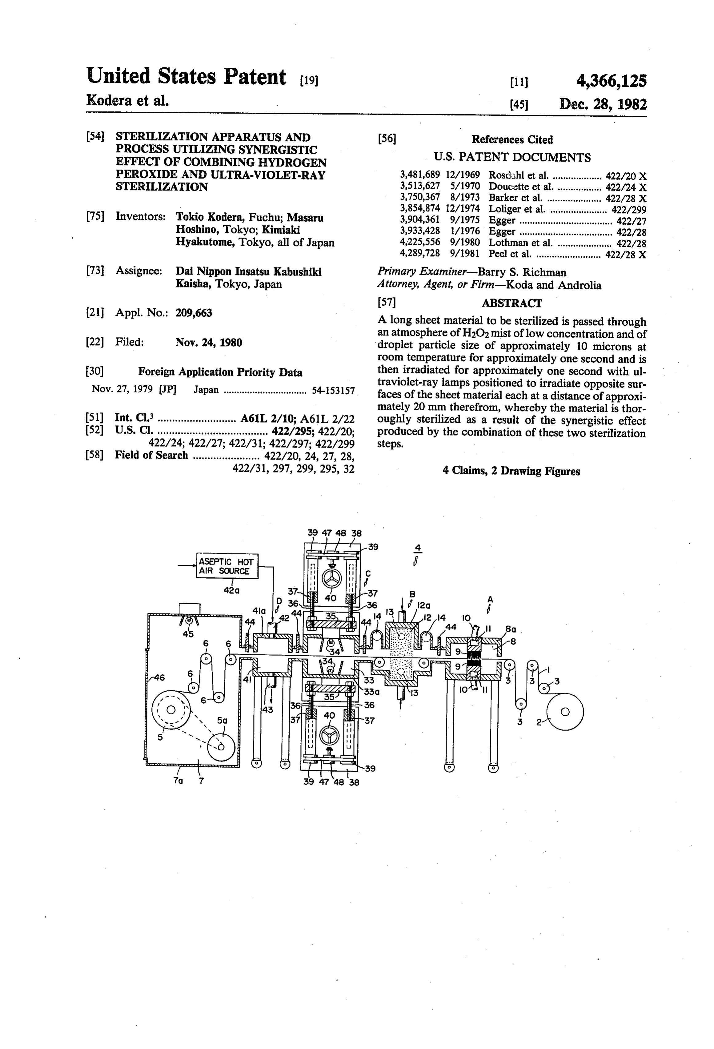
ASEPTIC HOt
AR SOURCE
NSN 3.
Page 2
Drawing sheet — no readable text.
Page 3
Drawing sheet — no readable text.
Page 4
low concentration at room temperature is applied onto
STERILIZATION APPARATUS AND PROCESS the outer surfaces of the material thereby to carry out UTELIZING SYNERGISTC EFFECT OF presterilization, a second step wherein the outer sur COMBINING HYDROGEN PEROXDE AND faces of the material thus coated with the hydrogen ULTRA-VIOLET-RAY STERILIZATION 5 peroxide film are irradiated with ultraviolet rays, BACKGROUND OF THE INVENTION thereby being further sterilized, and a third step wherein the material thus irradiated is dried with asep
This invention relates generally to techniques for tic hot air.
sterilizing articles particularly sheet materials. More 10 According to this invention in another aspect thereof, particularly, the invention relates to an apparatus and briefly summarized, there is provided a sterilization process for sterilizing materials in the form of long apparatus comprising: a plurality of housings communi sheets or strips, such as packaging materials, which can catively connected in sequence and enclosing respec be payed out from and taken up on rolls. More specifi tive aseptic chambers which are constantly under posi cally, the invention concerns the sterilization of such 15 tive pressure and adapted to permit the passage succes sheet materials by utilizing a remarkable, heretofore sively therethrough in one travel direction of a material unanticipated sterilization effect afforded by the com bined use of H2O2, i.e., hydrogen peroxide, and a UV, to be sterilized; hydrogen peroxide sterilizing means in one of the housings for applying a thin film of hydrogen i.e., ultraviolet, lamps.
In H2O2 sterilization as practiced heretofore, H2O2 at peroxide of low concentration at room temperature on room temperature has been used in some instances, but 20 the outer surfaces of the material thereby to carry out since the sterilizing or germicidal power thus obtained presterilization; ultraviolet-ray sterilizing means in a is weak, this technique has been inadequate for full housing downstream in said travel direction from the sterilization. For this reason, heated H2O2, which has a hydrogen peroxide sterilizing means for irradiating said powerful sterilization effect, has been used in many outer surfaces with ultraviolet rays; and drying means CaScS. 25 in a housing downstream from the ultraviolet-ray steril In the use of heated H2O2, however, steam and gase izing means for drying the material with aseptic hot air. ous H2O2 tend to leak out of the apparatus and give rise The nature, utility, and further features of this inven to environmental pollution, which has not been desir tion will be more clearly apparent from the following able for the operator. detailed description with respect to a preferred embodi Furthermore, since the H2O2 thus used is in liquid 30 ment of the invention as applied specifically to the ster form, the sterilization is of the wet type, and a large ilization of a packaging material when read in conjunc capacity drying step has been required, which has been tion with the accompanying drawings briefly described a difficulty in the design of the apparatus. In addition, below.
there has also been the possibility of some H2O2 remain ing because of inadequate drying. Still another problem 35 BRIEF DESCRIPTION OF THE DRAWINGS has been that the concentration of the H2O2 used princi In the drawings:
pally for sterilization has been 35 percent in most cases, whereby caution was necessary in handling this H2O2. and parts1 isshown
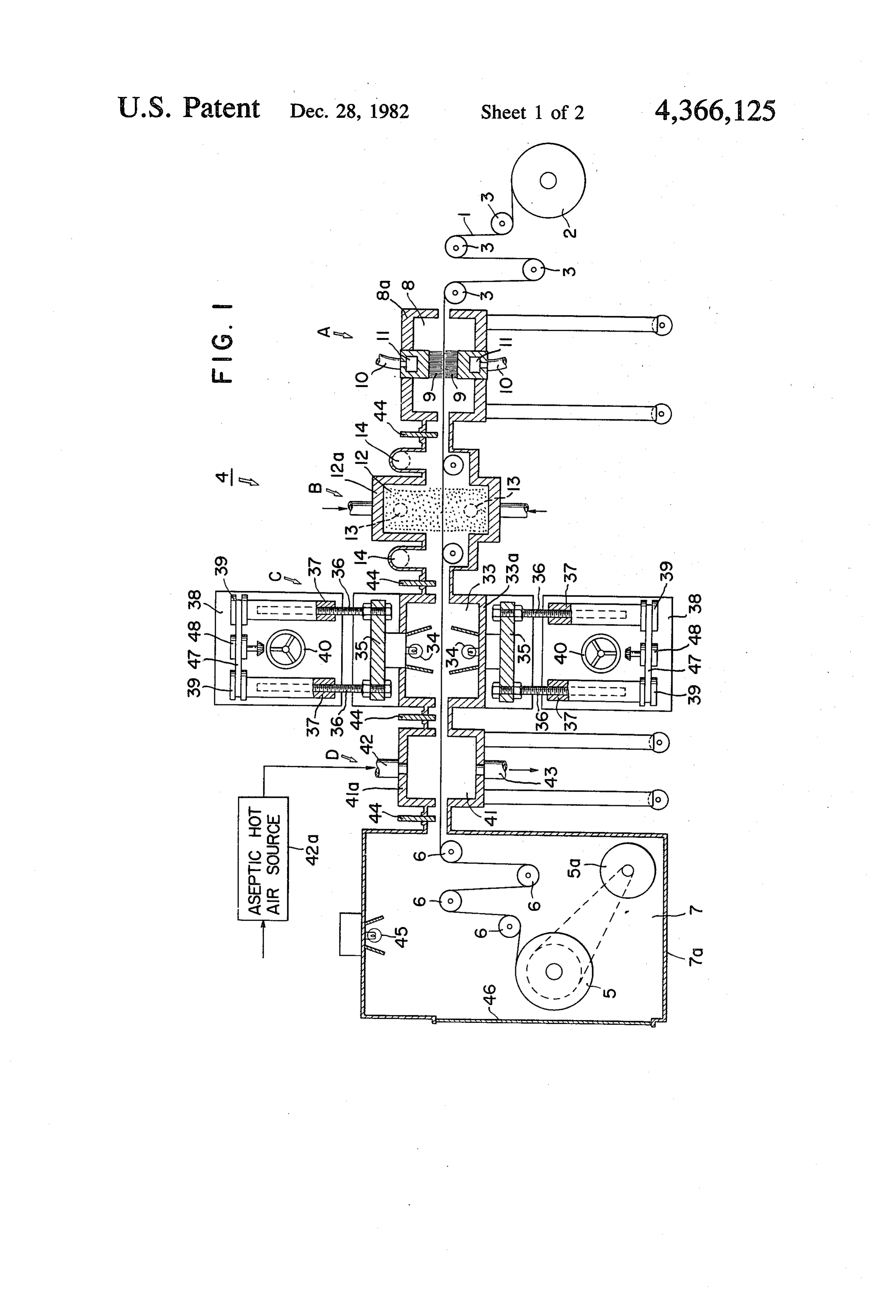
FIG. a schematic side view, with parts cut away in longitudinal section, showing the
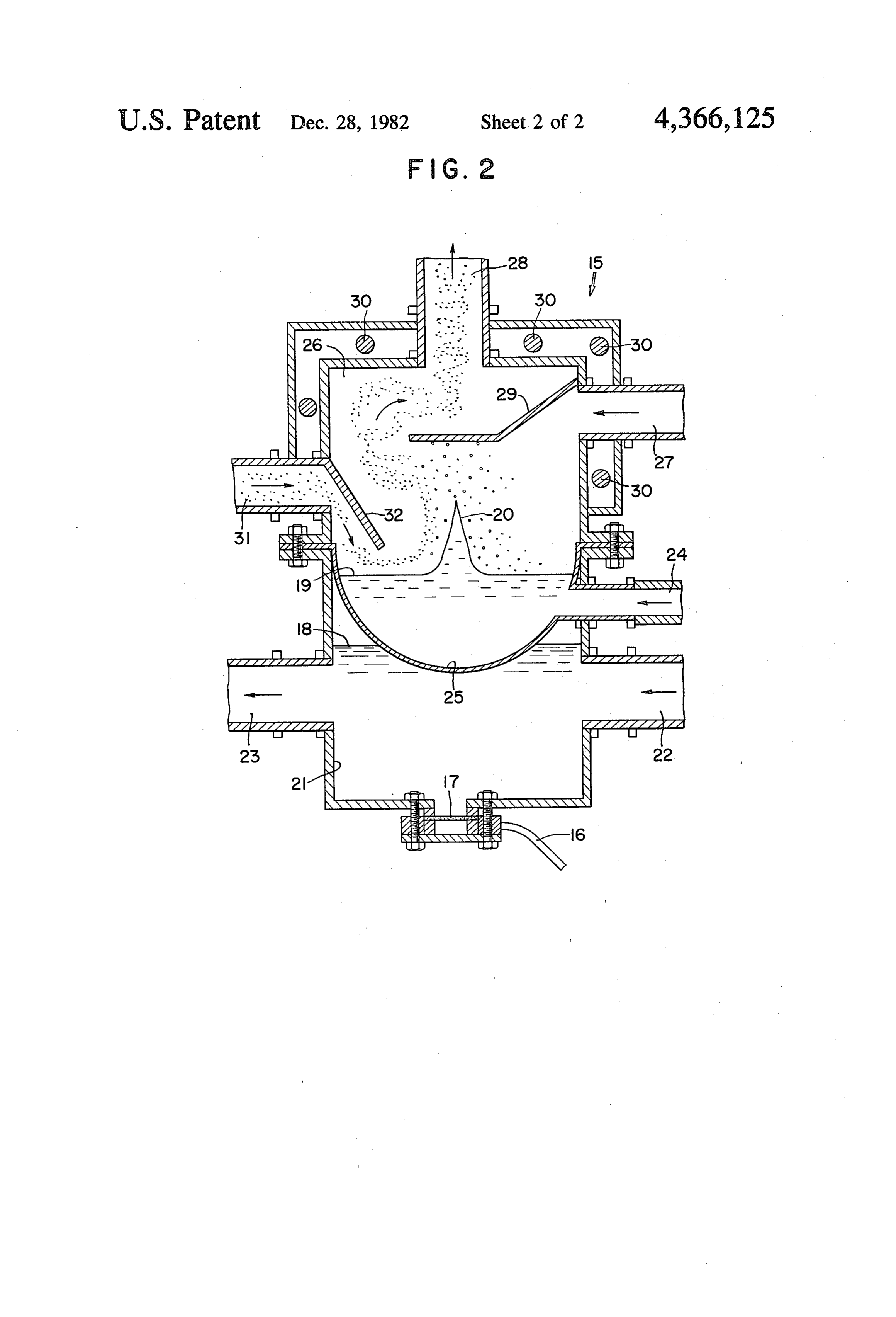
On the other hand, sterilization of packaging materi essential parts and their arrangement in an example of a als by irradiation with a UV lamp is a dry-type steriliza tion, in which a drying step is unnecessary, whereby it sterilization apparatus according to this invention; and is a simple and convenient method of great effectiveness section, of anaexample
FIG. 2 is relatively enlarged elevation, in vertical in sterilization. However, even with the use of powerful cidal liquid into a mistof for a device for atomizing a germi use in the apparatus illus
UV lamps, a long irradiation time is required for thor ough sterilization, and this long irradiation time has 45 trated in FIGURE 1.
given rise to damaging of the packaging material, low DETAILED DESCRIPTION OF THE ering of its heat-seal strength, and discoloration thereof. INVENTION Thus, these two sterilization methods, when carried Referring first to FIGURE 1, a packaging material 1 out independently for thorough sterilization, have had advantages and drawbacks. There has been a need for 50 in the form of a long strip or sheet is drawn from a feed overcoming these drawbacks. roll 2, caused to pass over and partially around guide rollers 3, and fed into a line of processing sections or
SUMMARY OF THE INVENTION devices. Then, after passing through a number of these In view of the above described circumstances, it is an processing devices as described hereinafter, the packag object of this invention to provide an apparatus and 55 ing material 1 enters a final take-up chamber 7 within a process for thoroughly sterilizing long sheet materials housing 7a, where it is passed around guide rollers 6 and without the accompaniment of the above described taken up on a tape-up roll 5 driven by a motor 5a. problems. This and other objects of the invention have During this travel from the guide rollers 3 to the been successively achieved by the use of the apparatus guide rollers 6, the packaging material 1 passes succes and process of the invention wherein, by the combined 60 sively through a cleaning device A for brushing the use of the sterilization effects of H2O2 and a UV lamp, opposite surfaces of the packaging material thereby to thorough sterilization is carried out, with minimum remove dust and dirt therefrom, an H2O2 device B for deleterious effect, by educing and utilizing a resulting causing H2O2 mist of low concentration at room termp synergistic effect. erature to adhere to both surfaces of the packaging According to this invention in one aspect thereof, 65 material, a UV device C for irradiating both surfaces of briefly summarized, there is provided a process for the packaging material with UV rays, and a drying sterilizing a material which comprises, in sequence, a device D for sterilizing and drying the packaging mate first step wherein a thin film of hydrogen peroxide of rial with aseptic heated air.
Page 5
The cleaning device A comprises essentially a dust element, a cooler, and a pump (not shown), entering and removal chamber 8 defined by a housing 8a having leaving the lower basin 21 through a supply inlet 22 and upstream and downstream walls respectively with inlet a discharge outlet 23, respectively. and outlet slits for passage of the packaging material 1, The germicidal liquid 19 is held in an upper basin 25, two brush devices 9 disposed in the middle part of the the bottom of which is immersed in the warm water 18 . chamber 8 for brushing the opposite surfaces of the in the lower basin 21. The upper basin 25 is supplied packaging material, and casings defining suction cham with the germicidal liquid from a tank and through a bers 11 and fixedly mounted in opposite lateral walls of heating element (both not shown) and an inlet pipe 24. the housing 8a, the brush devices 9 being respectively The above mentioned mist of the germicidal liquid is mounted on the inner faces of these suction chamber O formed almost continuously in a chamber 26 above the casings. Suction pipes 10 connected to an outside suc liquid germicide in the upper basin 25 and, wafted and tion source (not shown) are communicatively con carried by a current of aseptic air heated by a heating nected respectively to the suction chambers 11. element (not shown) and entering the chamber 26 Accordingly, the opposite surfaces of the packaging through an inlet pipe 27, passes out of the chamber 26 material 1 are brushed by the brush devices 9 as the 15 through a discharge pipe 28 at the top part thereof to be packaging material travels therebetween, and the dust conducted by the aforementioned mist-supplying pipes particles adhering by electrostatic attraction to the 13 into the mist atmosphere chamber 12 of the H2O2 packaging material are removed. The dust particles thus device B. During this movement of the mist in the removed are drawn into the suction chambers 11 and, chamber 26, it is caused to travel through a zig-zag path being sucked through the suction pipes 10, are dis 20 around a selection plate 29 which is in the form of a charged to the outside. baffle plate and functions to remove excessively large As an alternative to the removal of dust by suction, droplets of the mist.
the method of sweeping the dust off the surfaces of the Furthermore, the chamber 26 is provided there packaging material by blowing air thereagainst may be around with heating means 30, by which the rising mist resorted to. In any case, the removal of dust adhering to 25 is constantly kept warm. To the chamber 26 at one side the packaging material surfaces in the dust-removal thereof is connected a return pipe 31 through which chamber 8 serves to promote the sterilization. Depend mist discharged from the mist chamber 12 of the H2O2 ing on the necessity, an observation window may be device B through the mist-exhaust pipes 14 is returned provided in a wall of the housing 8a to afford observa into the chamber 26. A deflecting and shielding plate 32 tion of the dust-removal step in the chamber 8. 30 is disposed over the entrance of the return pipe into the The succeeding device B for causing H2O2 mist of chamber 26 to prevent reverse flow of the mist into the low concentration at room temperature to adhere to the return pipe 31.
two surfaces of the packaging material 1 has a mist The UV device C has a UV irradiation chamber 33 atmosphere chamber 12 which is defined by a housing within a housing 33a, which is provided with upstream 12a, and through the middle part of which the packag 35 and downstream slits through which the packaging ing material travels. Mist-supplying pipes 13 are pro material 1 from the mist chamber 12 is passed. UV vided to supply the H2O2 mist into the mist chamber 12 lamps 34 are provided in the UV irradiation chamber 33 respectively on opposite sides of the packaging mate at positions to project UV rays onto respectively oppo rial. site surfaces of the packaging material 1 passing The H2O2 mist to be thus supplied through the pipes 40 thereby. These UV lamps 34 are mounted at their bases 13 into the mist chamber is produced by ultrasonic on respective mounting heads 35 in symmetrically op waves generated by a sterilization or germicidal liquid posed state on opposite sides of packaging material at atomizing device as, for example, the device 15 shown positions outside of the housing 33a. in FIG. 2. More specifically, an ultrasonic wave vibra Each mounting head 35 is, in turn, supported on the tor 17 mounted on the bottom of a tank 21, described 45 inner ends of parallel screw rods 36 screw engaged with hereinafter, is caused to undergo resonation by an ultra respective tapped cylinders 37, the centerlines of these sonic wave oscillation circuit (not shown) connected to screw rods 36 and tapped cylinders 37 being substan the vibrator by a coaxial cable 16 and thereby generates tially perpendicular to the line of travel of the packag ultrasonic waves. These ultrasonic waves are propa ing material 1. The tapped cylinders 37 associated with gated through warm water 18 as a propagation medium 50 each mounting head 35 are mounted on a respective to a germicidal liquid 19 thereby to produce a mist of frame 38 in a manner such that they can rotate freely this liquid. Since the ultrasonic vibrator 17 is easily about their respective axes at specific positions relative damaged by the sterilization liquid, its ultrasonic waves to the frame 38. The tapped cylinders 37 thus rotatably are propagated via the warm water 18. The oscillation mounted on each frame 38 are synchronously intercou frequency of the ultrasonic waves thus generated is, for 55 pled by a mechanism comprising elements such as pull example, 1.0 MHz to 2.0 MHz. leys 39 respectively fixed to the cylinders 37 and an The germicidal liquid 19 thus acted upon by the ultra endless belt 47 passed around the pulleys 39 as well as a sonic waves is induced by the dispersive action thereof driving pulley 48. The driving pulley 48 is rotatably to assume a spire-like form 20 resembling that of water supported on each frame 38 and adjustably rotated by a in a waterspout and, further, the form of a fog, that is, an 60 handle 40 through a gear mechanism (not shown). H2O2 mist of low concentration at room temperature. Thus, by rotating the handle 40 and thereby rotating Most of the droplet particles of this mist are substan the pulley 48, the pulleys 39, and the tapped cylinders tially of the same size and, moreover, are very minute, 37, the screw rods 36 are extended or retracted, being approximately 10 microns in diameter. whereby the mounting head 35 and the UV lamp 34 The warm water 18 in this device is pure water con 65 mounted thereon are moved toward or away from the taining no impurities so as to facilitate its atomization packaging material 1. In this manner, the UV lamps 34 and is held in a lower basin. 21. This warm water 18 is on opposite sides of the packaging material 1 can be constantly circulated through a water tank, a heating adjusted to a suitable distance from the material 1 for
Page 6
irradiating the same with UV rays for sterilization of the ingly, large and elaborate drying equipment is unneces two surfaces thereof. This irradiation can be carried out sary.
with the UV lamps 34 positioned at a distance of ap Actual tests were carried out by using a sterilization proximately 20 mm from the surface of the material 1. apparatus of the above described construction and oper From the UV device. C, the material 1 enters asteril ation. As a result, it was found that it is possible to ization, and drying chamber 41 enclosed by a housing accomplish thorough sterilization against Bacillus Sub 41a of the drying device D. The housing 41a is also tilis of a concentration of 106/100 cm2 with a time for provided with upstream and downstream slits through passage of the material 1 through a mist atmosphere which the material 1 enters and leaves the chamber 4. zone of an H2O2 concentration of the order of 5 percent The housing 41a is provided at one lateral position 10 within 1 second and a UV irradiation time also within 1 thereof with an inlet pipe 42 for aseptic hot air supplied second. For comparison, equivalent tests were carried from an aseptic hot air source 42a. The aseptic hot air out respectively with each of the two sterilization car thus entering the chamber 41 sterilizes and dries the two ried out independently. As a result, it was found that surfaces of the material 1 and is exhausted from the sterilization with a time of passage of 10 seconds chamber 41 through a discharge pipe 43. 15 through only the H2O2 mist is inadequate and that with Shield plates 44, functioning as glands, are provided a time of 10 seconds of UV irradiation is also inade at joints between the housings of adjacent devices A, B, quate. .. -
C and D and the take-up chamber 7 to prevent or From these test results, it may be concluded that the greatly reduce leakage of dust-laden air, H2O2 mist, and combination of the sterilization by means of H2O2 mist hot air from the various chambers of these devices into 20 and that by means of UV ray irradiation, as afforded by the adjacent chambers. These shield plates 44 are the sterilization apparatus of this invention, produces a adapted to be adjustable, in the manner of gate valves, highly synergistic sterilization effect which is far toward and away from the material 1 in order to con greater than the sum of the sterilization effects of the form to the nature of the material 1 which may range two methods carried out independently. from an ordinary sheet material as illustrated to a sheet 25 As a result of other tests, it was confirmed that the material formed with recesses serving as containers. substitution of a tank containing H2O2 for immersion After being thus sterilized and dried in the drying therein of the material 1 for the H2O2 mist chamber 12 device D, the material enters the take-up chamber 7. produces a similar highly effective sterilization effect. This take-up chamber 7 is provided on a part (upper A corollary advantage arising from the above men wall part as viewed in FIGURE 1) thereof with a UV 30 tioned synergic sterilization effect is that the steriliza lamp 45 and in a wall part thereof near the take-up roll tion apparatus can be made compact, at least much 5 with a door 46 for taking out the aseptic roll 5 after it shorter than an apparatus relying on UV ray irradiation has been fully wound. only, which would require a long line of a great number Thus, in the sterilization apparatus of the above de of UV lamps for producing an equivalent sterilization scribed construction according to this invention, the 35 effect.
packaging material 1 is drawn out from the feed roll 2; As a further result of tests, it was found that when the is cleansed of dust in the dust-removal chamber 8; is sequence of the H2O2 mist step and the UV ray irradia passed through an atmosphere of H2O2 mist in the mist tion step, each of 1-second duration, was reversed, the chamber 12, where the H2O2 mist of low concentration sterilization result was inadequate, and only a steriliza at room temperature is caused to adhere thereto; is tion effect which was an arithmetic sum of the effects of passed, directly without being intentionally dried, into the two steps carried out independently was recogniz the irradiation chamber 33, where its two surfaces are able.
irradiated by the opposed UV lamps 34 and thus steril While this invention has been described with respect ized; is dried in the sterilization and drying chamber 41 to one preferred embodiment thereof wherein it is ap by aseptic hot air; and is wound into an aseptic roll 45 plied to the sterilization of a packaging material, the material in the take-up chamber 7. Instead of being invention is not thus limited in scope, being applicable wound up into a roll, the sterilized and dried material 1, to the sterilization of other kinds of articles such as upon leaving the sterilization and drying chamber 41, medical or surgical products and materials which are can be fed directly to forming means and thereby required to be in an aseptic state.
formed into an article, or it can be fed to a bag-making 50 We claim:
machine. 1. A sterilizing apparatus comprising: As described hereinbefore, the H2O2 mist of low a plurality of housings communicatively connected in concentration at room temperature is produced by ul sequence and enclosing respective aseptic cham trasonic waves and comprises droplet particles of a bers which are constantly under positive pressure particle size of the order of 10 microns. The above 55 and adapted to permit the passage successively described process wherein this mist is caused to adhere therethrough in one direction of a material to be to both surfaces of the material 1 is preferable to the sterilized;
application of the germicidal liquid by means of an hydrogen peroxide sterilizing means in one of the ordinary spray nozzle since, in contrast, the spray parti housing for applying a thin film of hydrogen perox cle size is large, and there is a possibility of the drying ide of low concentration at room temperature on being inadequate and giving rise to difficulties. Further the outer surfaces of the material thereby to carry more, the drying in the sterilization and drying chamber out presterilization, said sterilizing means applying 41 is accomplished almost instantaneously since the a mist of hydrogen peroxide onto the outer surface quantity of the fine droplets of the mist adhering to the of the material in sufficient quantity to produce surfaces of the material 1 is of an order of 10 microns 65 cloudiness and the mist comprises droplets of hy such as to merely cause clouding of the surfaces, and drogen peroxide of a particle size of approximately since the H2O2 adhering to the surfaces of the material 10 microns, the hydrogen peroxide sterilizing 1 is decomposed by the UV ray irradiation. Accord means further comprising a vessel containing hy
Page 7
drogen peroxide of low concentration at room said outer surface with the hydrogen peroxide film temperature, an ultrasonic generator coupled to thereon with ultra-violet-rays; and said vessel for generating a hydrogen peroxide mist drying means in a housing downstream from the ultra-violet-ray sterilizing means for drying the in the housing for said hydrogen peroxide steriliz 5 material with aseptic hot air. .. ing means through which the material is caused to 2. A sterilization apparatus according to claim 1 in travel, and means forming a chamber containing an which the ultraviolet-ray sterilizing means comprises at least two ultraviolet-ray lamps which are disposed on ultrasonic vibration propagation medium, said respectively opposite sides of the material passing propagation medium-containing chamber being 10 thereby and adjustable in position relative to the mate located between said ultrasonic generator and the rial. ;
bottom of said vessel, whereby said ultrasonic gen 3. A sterilization apparatus according to claim 1, erator acts through said propagation medium to which is adapted to sterilize a long sheet material and generate said mist without the generator directly 5 comprises a feed roll for paying out the sheet material contacting said hydrogen peroxide; and a take-up roll for taking up the sheet material after being dried in the drying means. - ultra-violet-ray sterilization means in a housing 4. A sterilizing apparatus according to claim 1, in downstream in said travel direction from the hy which the propagation, medium is warm water. drogen peroxide sterilizing means for irradiating t
Provenance
- Collection
- Cited prior art
- Original PDF
- patentimages.storage.googleapis.com →
- Filed
- 1980-11-24
- Pages
- 7
- Method
- pdftotext (the PDF's own text layer) + pdftoppm 300dpi page scans
- Source
- Google Patents bibliographic record
- Granted
- 1982-12-28
- Inventors
- Tokio Kodera; Masaru Hoshino; Kimiaki Hyakutome; Dai Nippon Printing Co Ltd
- Transcribed from
- patentimages.storage.googleapis.com →