patent · US4361135
Cooperative heat transfer and ground coupled storage system
30 November 1982
Page 1 — bibliographic record
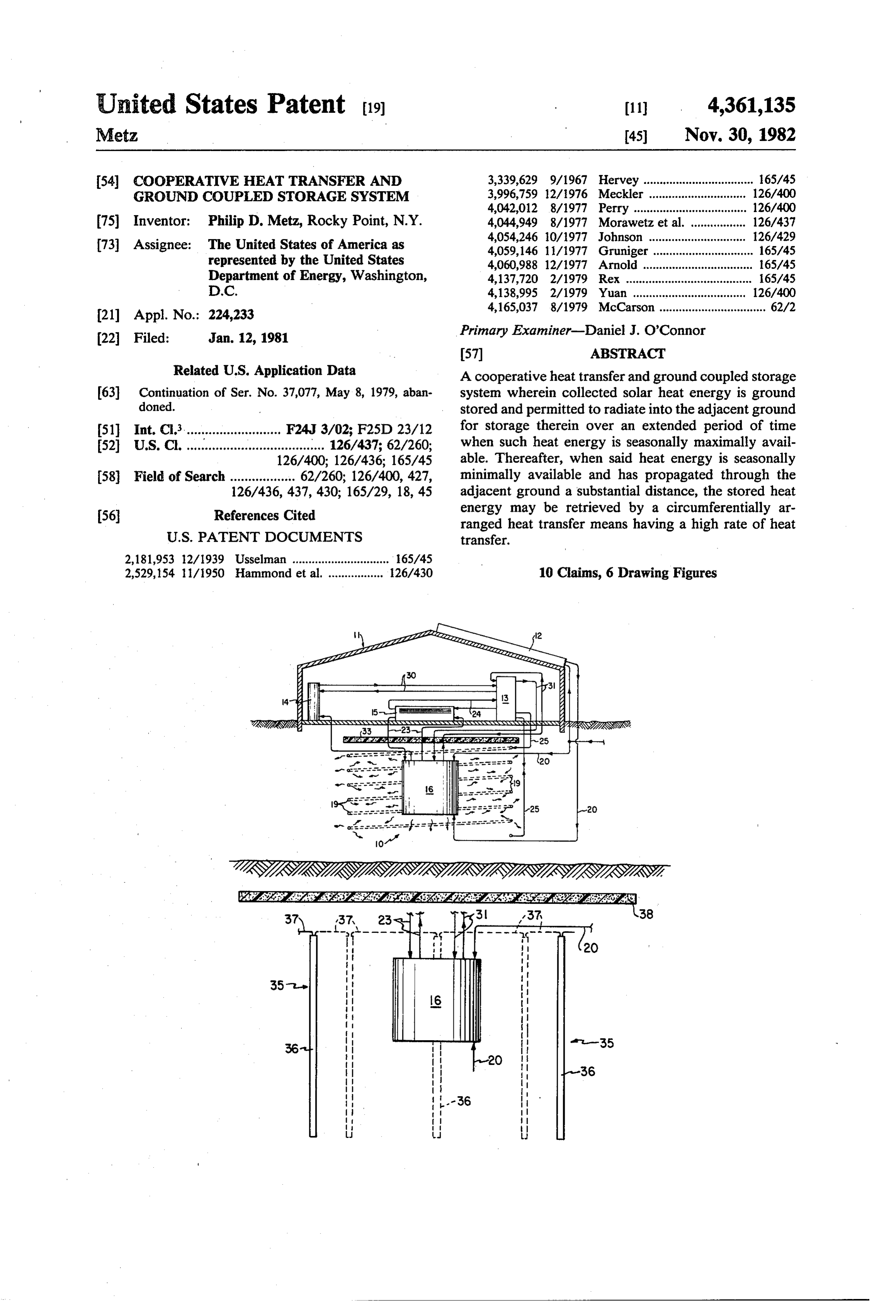
United States Patent (19) (11) 4,361,135 Metz 45) Nov. 30, 1982 54 COOPERATIVE HEAT TRANSFER AND 3,339,629 9/1967 Hervey .................................. 165/45 GROUND COUPLED STORAGE SYSTEM 3,996,759 12/1976 Meckler .. 126/400 4,042,012 8/1977 Perry .................. ... 126/400 (75) Inventor: Philip D. Metz, Rocky Point, N.Y. 4,044,949 8/1977 Morawetz et al. . 126/437 4,054,246 0/1977 Johnson ............. . 26/429 (73) Assignee: The United States of America as 4,059,146 11/1977 Gruniger. ... 165/45 represented by the United States 4,060,988 12/1977 Arnold .... ... 65/45 Department of Energy, Washington, 4,137,720 2/1979 Rex ..... ... 65/45 D.C. 4,138,995 2/1979 Yuan ....... 126/400 4,165,037 8/1979 McCarson ................................. 62/2
22 Filed: Jan. 12, 1981 Primary Examiner-Daniel J. O'Connor
Related U.S. Application Data A cooperative heat transfer and ground coupled storage 63 Continuation of Ser. No. 37,077, May 8, 1979, aban system wherein collected solar heat energy is ground doned. stored and permitted to radiate into the adjacent ground 51 Int. Cl........................... F24J 3/02; F25D 23/12 for storage therein over an extended period of time (52) U.S. C. ...................................... 126/437; 62/260; when such heat energy is seasonally maximally avail 126/400; 126/436; 165/45 able. Thereafter, when said heat energy is seasonally 58 Field of Search .................. 62/260; 126/400, 427, minimally available and has propagated through the 126/436, 437, 430; 165/29, 18, 45 adjacent ground a substantial distance, the stored heat energy may be retrieved by a circumferentially ar
ranged heat transfer means having a high rate of heat
2,181,953 2/1939 Usselman .............................. 165/45 2,529,154 1/1950 Hammond et al. ................. 26/430 10 Claims, 6 Drawing Figures
sitti
S2SSSSSSSNSSSSSSSSSSSSSSSSSSSaaSSSSSSSSSSSSSSSSSSS SS2 2.
36 1st-35
Page 2
Drawing sheet — no readable text.
Page 3
Drawing sheet — no readable text.
Page 4
ground coupled heat storage system of the invention be
COOPERATIVE HEAT TRANSFER AND GROUND used to provide a source of heat for a conventional heat COUPLED STORAGE SYSTEM pump and also to provide the heating or preheating of domestic hot water and of hot water for space heating.
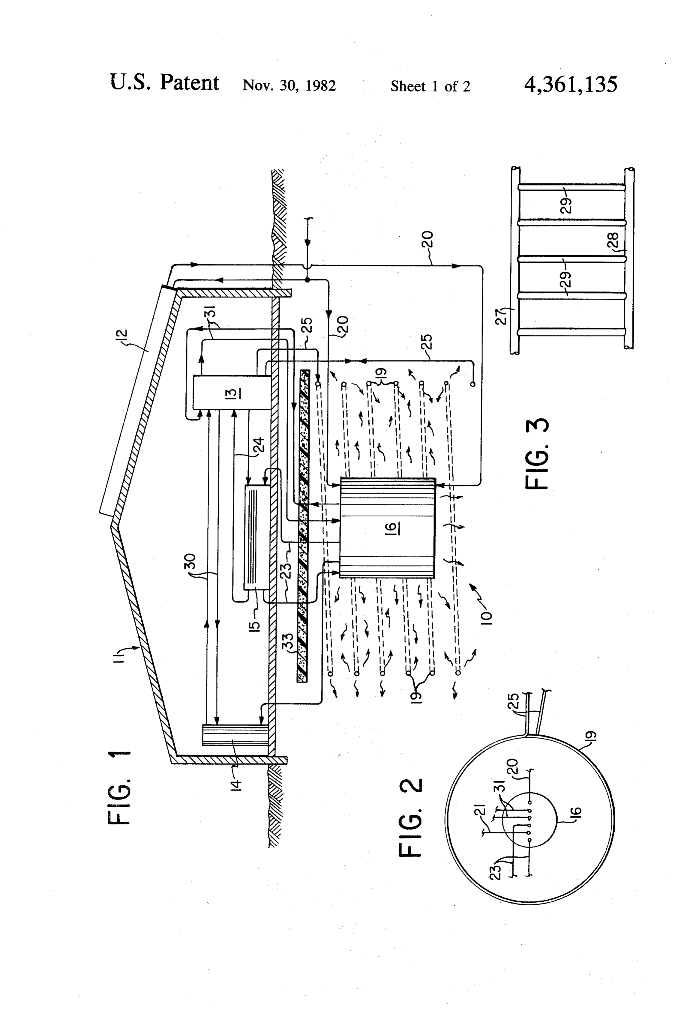
BACKGROUND OF THE INVENTION 5 When the heat pump is used for summer cooling, by The invention described herein was made or con appropriate circulation, the circumferentially arranged ceived in the course of, or under a contract with, the heat transfer means may serve to cool the condensed U.S. Department of Energy. fluid of the heat pump, thus effecting storage of heat in This is a continuation, of application Ser. No. 37,077, O the ground for subsequent retrieval. These and other filed May 8, 1979, now abandoned. aspects of the present invention will be seen with refer The present invention comprises improved means for ence to the following specification and the drawing. ground storage of collected solar heat energy in spaced BRIEF DESCRIPTION OF THE DRAWING storage areas to provide a temperature heat sink ground coupled with a high heat energy transfer means which 15 FIG. 1 is a side view partially in cross section illus may also function as a low temperature heat sink. The trating the ground coupled heat storage energy transfer use of a large mass of earth for the storage of collected system of the present invention in conjunction with a solar heat energy is known. Such concepts may be seen thermal load, solar collector means and a heat pump: in U.S. Pat. Nos. 3,339,629, 4,024,910 and 4,042,012. FIG. 2 is a plan view of the ground coupled heat U.S. Pat. No. 4,049,407 teaches the placement of an 20 storage system of FIG. 1;
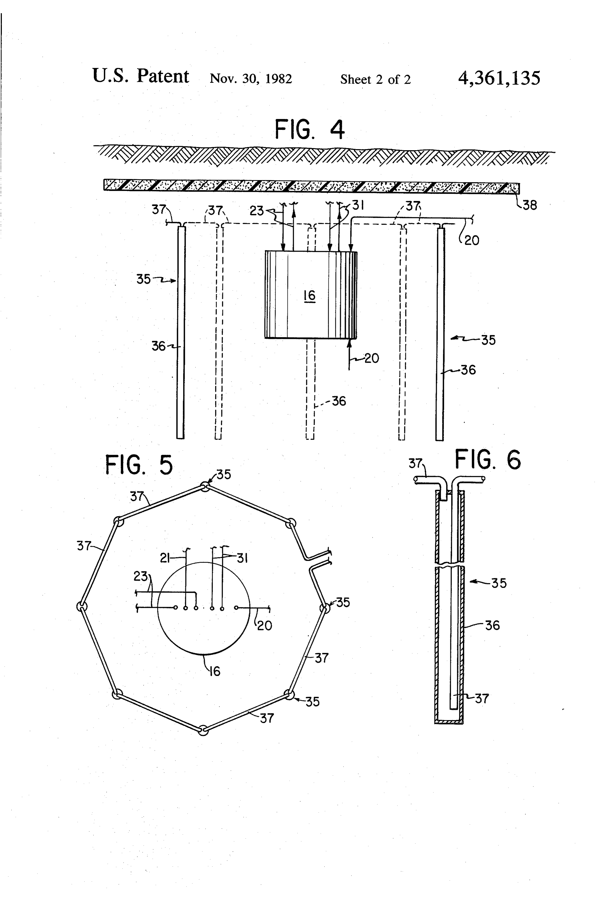
evaporator coil connected to a heat pump radially inter FIG. 3 illustrates an alternate embodiment of the heat mediate adjacent coils which place heat into the energy transfer means of the present invention; ground. Thus far, such prior art devices have failed FIG. 4 is a side view partially in cross section of a efficiently to utilize the ground storage of heat energy ground coupled heat storage system of the present in and have particularly failed efficiently to provide means vention employing another alternate circumferentially for retrieval of such heat energy over a long period of 25 arranged heat energy transfer means; time, and have failed to match efficiently the storage of FIG. 5 is a plan view of the storage system of FIG. 4; collected solar energy as it varies from season to season and with an efficient means of retrieval of such stored en ergy. It is the purpose of the present invention to dis theFIG. 6 is a detail showing the construction of one of close a system which solves these aforementioned prob means of FIGS. 4ofand 30 components the alternate heat energy transfer
lems.
DESCRIPTION OF PREFERRED
SUMMARY OF THE INVENTION EMBODIMENTS
The present invention seeks to take advantage of the fact that when heated energy is stored in the ground at 35 andWith reference to FIG. 1, a cooperative heat transfer relatively high temperatures, such energy gradually withground coupled storage system 10 in accordance radiates outwardly and is stored at predictable tempera illustrated. For the of the principles the present invention has been purpose of describing the present ture gradients in the ground surrounding the central invention heat sink. Collected solar heatenergy may be stored, for tem 10 is within an appropriate environment, the sys installed in conjunction with a structure 11 example, during the summer and fall when such avail 40 such as a house having a conventional roof mounted able heat energy is at its maximum in the central storage solar area or high temperature heat sink. In accordance with energy collector 12 and a heat pump 13. The lat a particular embodiment of the invention, such energy of ter, as is well known, by compression and evaporation may be stored as hot water contained within a storage a heat transfer medium selectively may be used to tank, the water being in heat exchange relationship with 45 heat or cool a thermal load. The heat generated by the respect to a fluid medium circulated through a solar heat pump may be used, for example, to heat domestic collector. hot water 14 (see fluid connector lines 30) or may be Disposed at a prescribed distance in the ground gen circulated through hot water convectors 15 (lines 24) to erally circumferentially about the central high tempera heat the interior of the structure 11. Alternatively, in ture heat sink is a heat transfer means capable of very 50 the summer by appropriate reversal of the cycle, the efficiently transferring heat energy from the ground to interior of the structure may be air conditioned. a thermal load (for example, the evaporator of a heat In accordance with the present invention, a unique pump). The circumferentially located heat transfer ground coupled storage system for collected heat en means may also serve to place heat into the ground ergy has been devised which includes a centrally lo when available but has as its primary function the re 55 cated heat energy storage means in the form of the tank trieval of heat energy placed at a prescribed distance in 16. By way of example, the tank 16 will be composed of the ground previously by the central high temperature heavy-duty low corrosion steel or will be constructed heat sink. This energy may, for example, have been of precast concrete rings. Where the thermal load is a initially stored during the summer and fall and later be house, the size of the tank 16 may be, for example, retrieved during the winter and spring by the heat trans approximately 8 feet in diameter by 8 feet in length and fer means when the wave of heat energy has reached will contain 3000 gallons of water. For purposes of the distantly spaced heat transfer means. In accordance domestic space conditioning, tank 16 should have a with particular embodiments of the present invention, capacity of say, 2000 gallons to 4000 gallons. A much the latter may be a continuous coil of pipe or horizontal larger tank would be prohibitively expensive. The inte headers interconnected by vertical, parallel pipes rior of the tank is connected with the solar collector 12 spaced from the central heat sink a sufficient distance to in order to transmit collected heat energy for storage in provide ground coupling and heat retrieval with respect tank 16. The tank 16 may be buried in the ground above thereto. A particular feature of the invention is that the the water table adjacent to or beneath the structure 11

Page 5
to be heated with approximately 4 feet of ground fill gates radially outwardly for subsequent retrieval of covering the tank. such energy, all as heretofore described. A heat transfer Circumferentially arranged with respect to the tank medium such as water may be circulated throughout 16 is a heat transfer and retrieval means 19, which in the the entire plurality of wells 35. FIG. 6 illustrates the embodiment described, may assume the form of a flexi construction of a typical well 35 having an outer casing ble, continuously coiled polyethelene pipe. The outside 36 of steel or plastic whose diameter may be for exam diameter of the pipe may be 1.5 inches or larger. The ple 23 inches. Entering the top of each casing 36 is an coils of the pipe are arranged vertically with respect to inlet pipe 37 which introduces water into the casing 36 each other at a distance of say 20 feet from the center of from an adjacent well 35. A second pipe 37 extending the tank 16, each coil being vertically 2 feet to 3 feet O for substantially the length of casing 36 is adapted to apart, the total comprising a length of approximately withdraw water from the bottom of the casing 36 and to 300 to 600 linear feet. circulate the water into an adjacent well 35. By this For simplicity is describing the interrelation between means, heat energy absorbed by the respective casings the above components, fluid connections between two 36 can be retrieved when desired.
or more such components have been indicated schemat 15 As illustrated in connection with the embodiment of ically and direction of flow, is shown by the use of ar FIGS. 1 and 2, a polystyrene thermal shield or layer 33 rows. Circulating pumps and valving to achieve the overlies the entire ground coupled storage system. In indicated flows have been omitted.
Typically, in the summer and fall energy from the this embodiment, the thermal shield acts to prevent a migration of stored heat energy upwardly into the over solar collector circulating through line 20 will be stored 20 lying ground and as a dual function, acts to prevent as heated water in the tank 16. Stored heated water escape of heat energy from the structure 18. In the from line 21 can be used if desired during this period as embodiment of FIG. 4, which by way of contrast is domestic hot water or can be used to preheat domestic located adjacent to a structure (not shown) to be space hot water. So long as the temperature of heated water in conditioned instead of underlying such structure, the tank 16 exceeds 100 F., it may also be used to provide 25 shield 38 extends for some distance radially beyond the interior heating by circulating the water directly perimeter of the ground storage system. In this embodi through connector 22 through line 23. Primarily, how ment, since shield or layer 38 tends to be impervious to ever, tank 16 is intended to be used for heat storage at moisture, it can act not only to shield the storage system high temperatures when available solar energy is at its from thermal loss which may occur through the overly maximum. In the winter, heat will continue to be depos 30 ing ground, but also may shield the storage system from ited in the tank 16 from the solar collector 12 when rain water or melting snow which could otherwise available and heat from the tank will be used to heat the percolate downwardly through the system to cause the thermal load directly through line 23 or through the system's stored energy to be depleted. agency of the heat pump 3 (lines 24) when needed. Such The ground coupled heat storage and heat transfer use will lower the tank temperature until it becomes 35 and retrieval elements are specifically designed and relatively inefficient to use such heat as a source (below configured to provide both long-term heat storage and 40 F. as a source of heat for heat pump 13) although the also high heat transfer rates when needed. The result is heat stored in the tank 16 will be reinforced to some a space conditioning system which uses less purchased extent by retrieval of heat stored in the ground sur energy and a smaller and less expensive solar system for rounding the tank 16. a given load. Furthermore, more heat energy may be During the summer, heat will be deposited in the stored efficiently with less capital expense, such storage ground through pipe 19 by the heat pump 13 through taking place during seasons when it is highly desirable lines 25, the ground being cooler than the air at this to maximize heat storage, with subsequent inexpensive time. However, in the winter, the wave of heat energy and highly efficient retrieval of stored energy which has whose source is heat deposited in tank 16, will have 45 migrated radially outwardly toward the heat transfer travelled to the vicinity of circumferential heat transfer and retrieval means 19. Heat is effectively stored at high means 19. At this time, the circumferentially arranged temperature at relatively low cost, and due to ground heat transfer means 19 may be called upon to transfer coupling and the use of surrounding earth as an inexpen heat continuously and over a long period as such heat is sive storage means, such trapped heat is later retrieved retrieved from the large ground mass intermediate the SO when needed.
tank 16 and the heat transfer retrieval means 19. Such FIG. 3 illustrates another alternate construction heat is available for use by the heat pump 13. Thus, heat which the heat transfer and retrieval means 19 may placed in the ground during the summer and fall for assume. In this form, vertically spaced, horizontal head storage in tank 16 is subsequently retrieved during the ers 27 and 28 are arranged in parallel relationship with winter months by the peripheral heat transfer and re 55 intermediate vertical tubes 29. Since flow through head trieval means 19. ers 27 and 28 is much shorter than the combined flow FIGS. 4-6 illustrate yet another embodiment which would be through vertical pipes 29, the temperature the circumferential heat transfer means of the present gradient within the headers is much lower than would invention may assume. In this embodiment, with the occur through the continuous coil 19 as illustrated in tank 16 at the center of the ground coupled storage 60 FIG. 1. The advantage of the configuration of FIG. 3 is system, a plurality of deep wells 35 may be sunk verti that much cally and equidistantly about 20 feet from the center of lower pumphigher heat transfer rates are possible, while power would be required. A correlative tank 16. In the illustrated embodiment, the upper ends benefit of this configuration is the possibility that a of the wells 35 are below frost level and may extend for leaking pipe section might be jettisoned without seri say 30 feet to 50 feet so long as the lower ends thereof 65 ously affecting the overall capacity of the system. remain above the water table. As indicated in FIG. 5, eight wells 35 are so arranged and will function to inter hasItbeen will be understood that the foregoing description of particular embodiments and has been there cept the wave of heat energy from tank 16 as it propa fore representative. In order to appreciate fully the
Page 6
scope of the invention, reference should be made to the (b) means for transferring heat from said solar energy appended claims. collector to a fluid stored in said tank; I claim: (c) a structure to be heated; 1. A cooperative ground coupled heat storage and (d) heat exchange means within said structure; and retrieval system comprising: 5 (e) means for circulating a fluid heat transfer medium (a) a tank capable of storing a substantial quantity of between said heat exchange means and said cir fluid, said tank being located in the ground below cumferential heat transfer means, whereby heat the freezing level and above the water table and may be transferred from the ground to said struc ture.
being constructed to permit conduction of heat 10 4. A system as described in claim 3, further compris therefrom into the surrounding ground; and ing thermal shield means in the form of a layer of insu (b) circumferential heat transfer means for the trans lating material located above said tank and said circum fer of heat to and from the ground surrounding said ferential heat transfer means for preventing the flow of tank, said means further comprising a plurality of heat upwards.
vertically arranged deep wells each consisting of a 15 5. A system as described in claim 4, wherein said casing, fluid inlet means at the top of said casings, thermal shield means extends for a distance beyond the and fluid outlet means extending into said casings perimeter of said circumferential heat transfer means generally the entire length thereof to withdraw and is impervious to rain and melting snow to prevent water from the bottom of said casings, and means the passage of water from above through the storage for the interconnecting of the inlet and outlet 20 system, M means of said casings such that a fluid heat transfer 6. A system as described in claim 4, wherein said heat medium may be circulated into the top of each exchange means includes means for heating hot water. casing and withdrawn from the bottom of said 7. A system as described in claim 6, wherein said heat casing and transmitted into the top of an adjacent 25 exchange means includes a heat pump. casing, said wells being constructed to allow the 8. A system as described in claim 7, further compris flow of heat between the ground and said heat ing means associated with said heat pump for circulat transfer fluid and each being spaced a predeter ing a fluid heat transfer medium heated by said heat pump into said circumferential heat transfer means to mined distance from said tank, said distance being deposit selected so that heat deposited in said tank during 30 while heat into the ground surrounding said tank the warmer, sunnier months and conducted into cooling said structure. the ground will reach said wells during the cooler, heat 9. A system as described in claim 3, wherein said fluid darker months, whereby the heat may be retrieved contain transfer medium is water, the tank is adapted to for use as it is needed during the heating season. a quantity of water within about 2,000 to 4,000 gallons, and said circumferential heat transfer means 2. A system as described in claim 1, wherein said 35 extends for a distance vertically below the freezing predetermined distance is about 20 feet. level.
3. A system as described in claims 1 or 2, further 10. A system as described in claim 1, wherein said comprising: wells extend from 30 to 50 feet, (a) a solar energy collector; k k sk k k
Provenance
- Collection
- Cited prior art
- Original PDF
- patentimages.storage.googleapis.com →
- Filed
- 1981-01-12
- Pages
- 6
- Method
- pdftotext (the PDF's own text layer) + pdftoppm 300dpi page scans
- Source
- Google Patents bibliographic record
- Granted
- 1982-11-30
- Inventors
- Philip D. Metz; US Department of Energy
- Transcribed from
- patentimages.storage.googleapis.com →