patent · US4349228
Method for dewatering a subterranean formation via a borehole
14 September 1982
Page 1 — bibliographic record
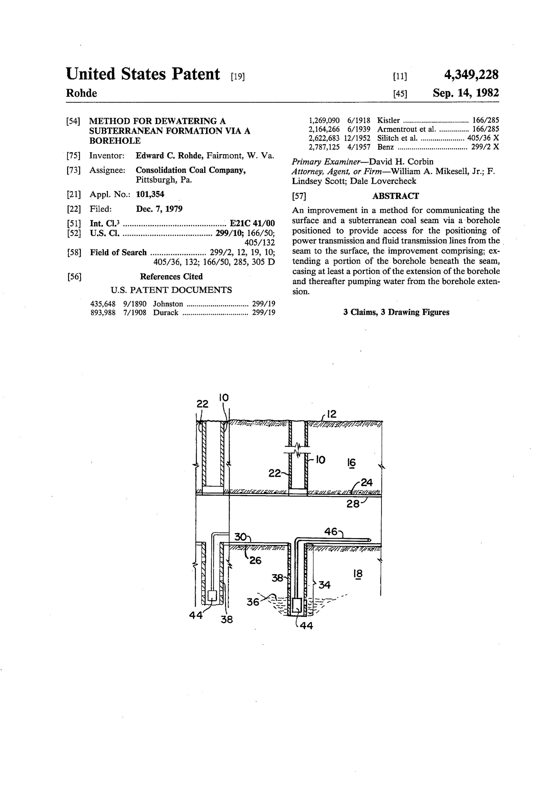
United States Patent (19) 11 4,349,228 Rohde 45) Sep. 14, 1982 54 METHOD FOR DEWATERING A 1,269,090 6/1918 Kistler ................................. 166/285 SUBTERRANEAN FORMATION WIAA 2,164,266 6/1939 Armentrout et al. ... 166/285 BOREHOLE 2,622,683 12/1952 Silitch et al.......... ... 405/36 X 2,787,125 4/1957 Benz ................................... 299/2X 75 Inventor: Edward C. Rohde, Fairmont, W. Va. s
Primary Examiner-David H. Corbin 73 Assignee: Consolidation Coal Company, Attorney, Agent, or Firm-William A. Mikesell, Jr.; F. Pittsburgh, Pa. Lindsey Scott; Dale Lovercheck (21) Appl. No.: 101,354 57 ABSTRACT 22 Filed: Dec. 7, 1979 An improvement in a method for communicating the 51) Int. Cl. .............................................. E21C 41/00 surface and a subterranean coal seam via a borehole 52 U.S. C. ........................................ 299/10; 166/50, positioned to provide access for the positioning of 405/132 power transmission and fluid transmission lines from the 58 Field of Search ......................... 299/2, 12, 19, 10; seam to the surface, the improvement comprising; ex 405/36, 132; 166/50, 285, 305 D tending a portion of the borehole beneath the seam, 56) References Cited casing at least a portion of the extension of the borehole and thereafter pumping water from the borehole exten
435,648 9/1890 Johnston ............................... 299/19 893,988 7/1908 Durack ................................. 299/19 3 Claims, 3 Drawing Figures
Page 2
Drawing sheet — no readable text.
Page 3
after development of the mine in the vicinity of the
METHOD FOR DEWATERING A borehole.
SUBTERRANEAN FORMATION VIA A In the discussion of the figures, the same numbers will BOREHOLE be used to refer to the same or similar components throughout.
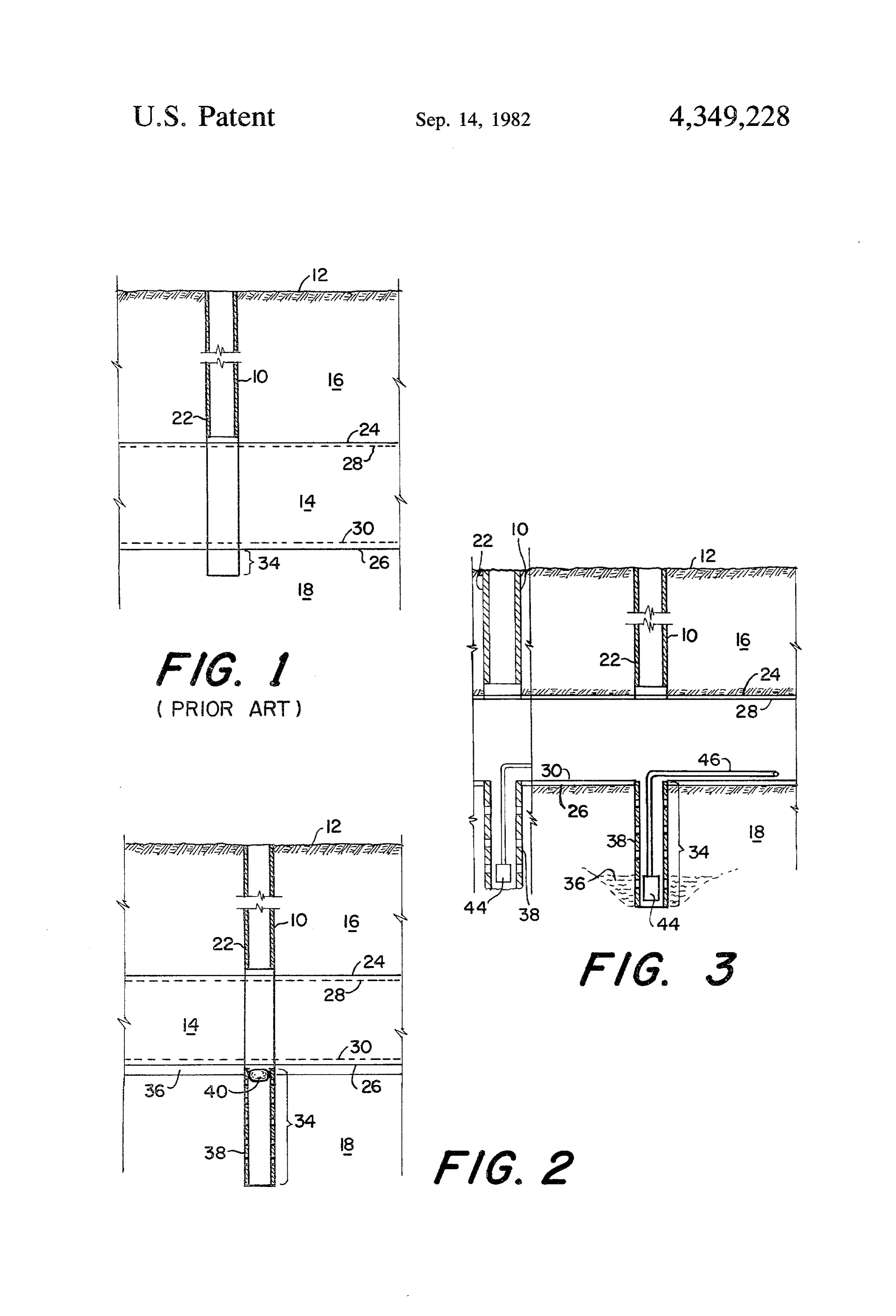
This invention relates to the dewatering of subterra In FIG. 1 and a borehole 10 is positioned from surface nean formations. 12 through a formation 16 to a coal seam 14 which This invention further relates to methods for dewa overlies another subterranean formation 18. The bore tering coal seams in the vicinity of coal mines. hole, as drilled, is extended through coal seam 14 for a This invention further relates to an improvement 10 short distance 34 into subterranean formation 18 to whereby boreholes commonly used for the positioning establish thickness of the coal seam and the like. Bore of power transmission and fluid transmission lines from hole 10 is then desirably cased with a casing 22 which is the surface to the coal mine are extended to provide a normally cemented in place, as known to those skilled borehole beneath the level of the coal mine from which in the art, to a depth slightly above the top 24 of coal water may be removed. 5 seam 14.
In the mining of coal of various grades, from mines In FIG. 2, a borehole 10 is positioned through forma beneath the surface, a commonly occurring problem is tion 16 and cased as shown in FIG. 1 but borehole 10 is water. Excess water in the mine area results in the oper extended for a greater distance 34 beneath the bottom ation of the mining equipment in mud which results in a 26 of coal seam 14 and cased with a casing 38 which is substantial decrease in the efficiency of mining opera desirably perforated to permit the entry of water. While tions. Further, the digging of sumps in mines to remove depths below the seam of up to about 50 feet are consid water as presently practiced is time consuming and ered suitable for most mines greater depths can be used imposes an additional equipment requirement. The dis if required. The top and bottom of the future mine are advantages of the excessive water in the mining opera shown by dotted lines 28 and 30. A packer 40 is posi tions are well known and constitute the aforementioned 25 tioned in borehole 10 in the upper portion of the perfo inefficiency in operations, the added disadvantages of rated casing and just beneath the bottom 30 of the mine. hauling wet products, which tend to stick to the inside A water table36 is shown in FIG. 2 as being slightly of the haulage vehicles and the like as well as a number beneath the bottom of coal deposit 14. of other problems not the least of which are electrical In FIG. 3, a pump 44 has been positioned in well bore hazards associated with the presence of the excessive 30 10 to pump water via a line 46 to mine drainage or the water in the mine vicinity. The excess water may be like. Water table 36 has been lowered as shown by naturally present in the subterranean formations or the pumping through line 46. The mine has been completed water may be artificially introduced water from nearby as shown by solid lines 28 and 30 showing the top and mining operations or even from the operations carried bottom of the mine. As will be evident from FIG. 3 the out in the particular mine for which the drainage system 35 top of perforated casing 38 is desirably below the bot is designed. As is well known to the art, many mining tom of the mine so that the casing is not disturbed by the operations involve the use of water which may then use of mining machinery and the like.
constitute excess or undesired free water in the mine. In the practice of the improvement of the present In any event, the removal of such water is necessary invention, it is possible that the subterranean formations and has been attempted by a variety of techniques here could be dewatered from surface 12 before mining tofore. through the area, although such is less preferred since it In the development of such mines, boreholes are requires the installation of expensive strings of piping, typically drilled from the surface to the mine seam at pumps and the like which must be removed prior to selected intervals to facilitate the entry of power trans mining through the area. The preferred practice of the mission and fluid transmission lines into the mine. Typi 45 method of the present invention comprises the use of a cally the boreholes are drilled to the coal seann and for packer positioned in the top of perforated casing 38 so a short distance through the coal seam to establish that that mining operations can pass above the portion of the the seam has been reached with the boreholes thereafter borehole extending beneath the bottom of coal seam 14 being cased to a depth slightly above the top of the coal with the portion of borehole 10 beneath coal seam 14 seam. The borehole is then used for power or fluid 50 being left relatively undisturbed so that upon the re transmission line access as required as the mine ad moval of packer 40 pumping of water from the portion vances through the seam beneath the borehole. It has of borehole 10 beneath coal seam 14 can be readily now been found that the drainage of mines is facilitated commenced by simply installing a pump and transmis by an improvement in such methods, whereby the bore sion line for the removal of water to a mine water dis hole is drilled to a depth extending substantially beneath 55 posal system or the like. The water removed can be the bottom of the coal seam and thereafter cased, desir either naturally occurring subterranean water or artifi ably with a perforated casing, to a depth constituting at cially supplied subterranean water as discussed previ least a portion of the total depth of the borehole beneath ously. It is desirable that a packer or the like be used so the coal seam with water thereafter being pumped from that the portion of borehole 10 extending beneath the the borehole extension beneath the coal seam. 60 bottom of coal seam 14 does not become plugged with FIG. 1 is a schematic diagram of a borehole as typi debris and the like as mining operations proceed past cally used to penetrate a subterranean coal seam; borehole 10. Desirably at least a portion of borehole 10 FIG. 2 is a schematic diagram of an embodiment of is cased beneath coal seam 14 so that water can be re the present invention showing a borehole positioned moved from borehole 10 without plugging the pumps through a subterranean coal seam and extending for a 65 and the like. Desirably all of the portion of borehole 10 substantial depth beneath the coal seam; and, extending beneath coal seam 14 is cased with perfora FIG. 3 is a schematic diagram of an embodiment of tions being positioned in the casing as required for the the present invention showing the borehole of FIG. 2 flow of water into borehole 10. The pumps used are
Page 4
conventional pumps as known to those skilled in the art mining through the deposit in the area of the casing and do not warrant further discussion. comprising,
A primary advantage of the present invention lies in providing a borehole said borehole comprising a the use of a borehole which is already required in the 5 seam portion extending through said seam normal operation of a mine which is adapted by the and a lower portion below said seam portion, improvement of the present invention to accomplish a providing a perforated casing in said lower portion of second required objective with a minimum of added said borehole, said casing having a top portion; expense and difficulty. The positioning of a cased por providing a packer in said top portion of said perfo tion of borehole 10 beneath coal seam 14 by the im rated casing, provement of the present invention is relatively inex 10 mining said seam, and then removing said packer from said top portion of said perforated casing, pensive and permits the positioning of a plurality of providing a pumping means in said perforated cas potential drainage sumps which can be used as needed ing in said lower portion of said borehole, thereaf throughout a wide area of a mine. ter pumping water from said lower portion of said Having described the present invention by reference 15 borehole.
to certain of its preferred embodiments, it is pointed out 2. The method of claim 1 wherein said lower portion that the embodiments shown are illustrative rather than limiting in nature and that many variations and modifi of said borehole extends up to about fifty feet below said cations are possible within the scope of the present Sea.
invention. Many such variations and modifications may ity3. of The method of claim 1 further comprising a plural be considered obvious and desirable by those skilled in 20 packer said boreholes, each said borehole having a the art upon a review of the foregoing description of each saidin perforated said top portion of said perforated casing, casing being in said lower portion preferred embodiments, 1. A method of installing a perforated casing beneath of said borehole. k s a subterranean seam of a carbonaceous deposit and 25
Provenance
- Collection
- Cited prior art
- Original PDF
- patentimages.storage.googleapis.com →
- Filed
- 1979-12-07
- Pages
- 4
- Method
- pdftotext (the PDF's own text layer) + pdftoppm 300dpi page scans
- Source
- Google Patents bibliographic record
- Granted
- 1982-09-14
- Inventors
- Edward C. Rohde; Consolidation Coal Co
- Transcribed from
- patentimages.storage.googleapis.com →