patent · US4291750
Selective extraction heat storage unit
29 September 1981
Page 1 — bibliographic record
United States Patent (19) (11) 4,291,750 Clyne et al. 45) Sep. 29, 1981 54) SELECTIVE EXTRACTION HEAT STORAGE FOREIGN PATENT DOCUMENTS
UNIT
52-16840 8/1977 Japan ............................... 165/104 S (75) Inventors: Arthur J. Clyne, Alma; John E. 398927 9/1933 United Kingdom ............ 165/104 S Knarr, Lansing; Stanley Miller, Primary Examiner-Albert W. Davis
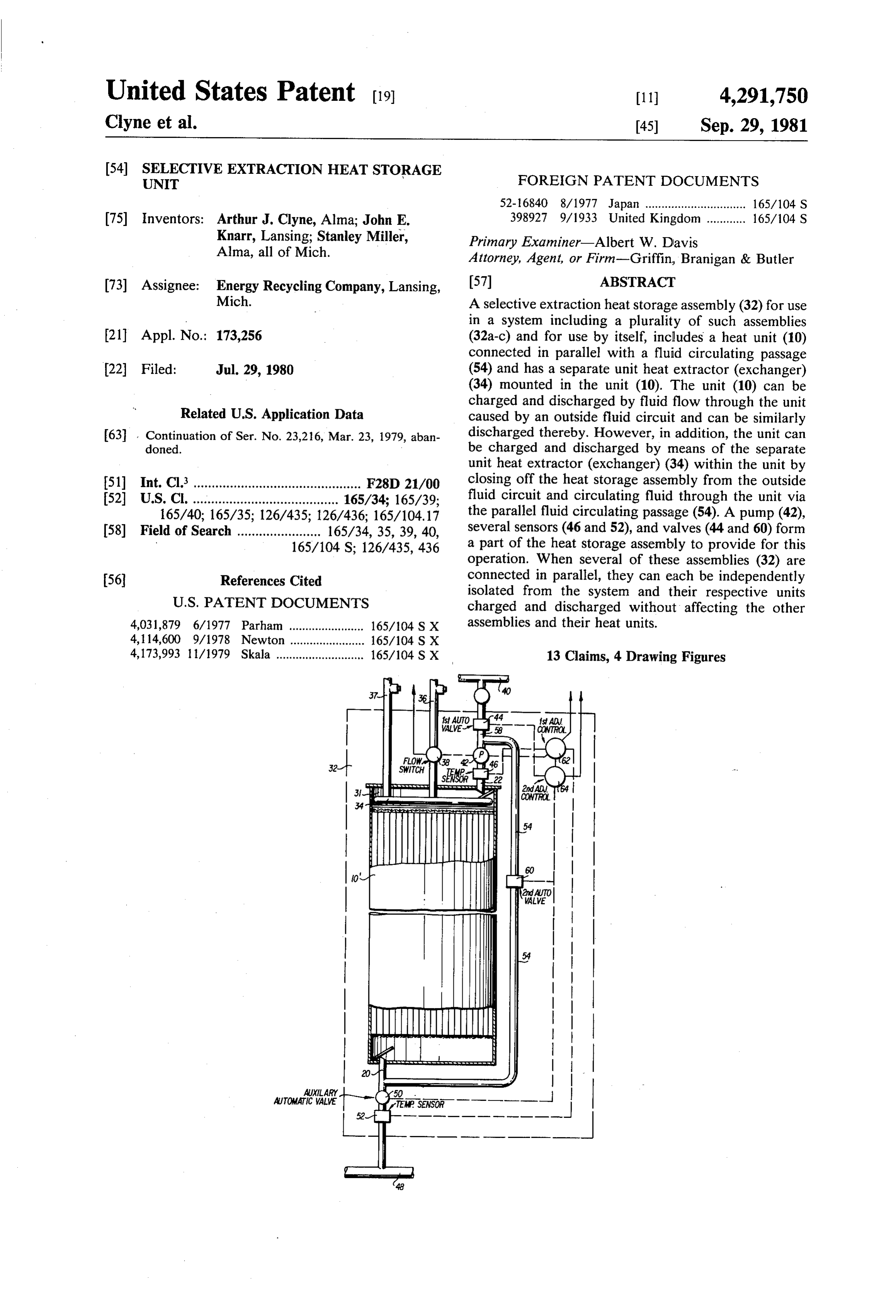
Alma, all of Mich. Attorney, Agent, or Firm-Griffin, Branigan & Butler (73) Assignee: Energy Recycling Company, Lansing, (57) ABSTRACT Mich. A selective extraction heat storage assembly (32) for use in a system including a plurality of such assemblies 21 Appl. No.: 173,256 (32a-c) and for use by itself, includes a heat unit (10) connected in parallel with a fluid circulating passage 22 Filed: Jul. 29, 1980 (54) and has a separate unit heat extractor (exchanger) (34) mounted in the unit (10). The unit (10) can be charged and discharged by fluid flow through the unit
Related U.S. Application Data caused by an outside fluid circuit and can be similarly 63 Continuation of Ser. No. 23,216, Mar. 23, 1979, aban discharged thereby. However, in addition, the unit can doned. be charged and discharged by means of the separate unit heat extractor (exchanger) (34) within the unit by 51 Int, C.3 closing off the heat storage assembly from the outside (52) fluid circuit and circulating fluid through the unit via 165/40; 165/35; 126/435; 126/436; 165/104.17 the parallel fluid circulating passage (54). A pump (42), (58) Field of Search ....................... 165/34, 35, 39, 40, several sensors (46 and 52), and valves (44 and 60) form 165/104 S; 126/435, 436 a part of the heat storage assembly to provide for this operation. When several of these assemblies (32) are (56) References Cited connected in parallel, they can each be independently
isolated from the system and their respective units charged and discharged without affecting the other 4,031,879 6/1977 Parham ....................... 165/104 S X assemblies and their heat units.
4,173,993 l M1979 Skala ........................... 165/104 S X 13 Claims, 4 Drawing Figures
Page 2
Drawing sheet — no readable text.
Page 3
FLOW Ra E3 swife 42 SPs
SENSOR 22
yvyx YVN ANYayyyy
Nes
I0 F
| - WALWE
I T awawaYawawa Yax"YYYYYahayaww.www.waway wayway
AUTOMATIC 5.1 - EMP SENSOR -
Page 4
ing passage tube and a unit heat extractor (heat ex
SELECTIVE EXTRACTION HEAT STORAGE UNIT changer) which is in series with the unit. The unit is normally charged by closing the parallel fluid circula
This is a continuation, of application Ser. No.23,216, tion passage and causing transfer fluid flow from an filed Mar. 23, 1979 now abandoned. external system through the unit and its associated heat BACKGROUND OF THE INVENTION extractor (exchanger). Although the system can also be discharged in this manner, it can, in addition, be dis
This invention relates broadly to heat storage systems charged by isolating the assembly from the external and particularly to systems for storing solar energy and system with valves, circulating transfer fluid through recycled discharge heat. 10 the parallel fluid circulation passage, and discharging As used herein, the terminology "heat storage unit" heat with the unit heat extractor (exchanger). The unit refers to an energy assembly of one or more cells which could also be charged by inserting heat into a unit heat receives energy in the form of heat, stores this energy, extractor (heat exchanger) while circulating the fluid. A and thereafter furnishes this energy in the form of heat separate pump and various valves and sensors are in upon demand therefor. 15 cluded in the assembly to accomplish the above. U.S. Pat. No. 4,127,161 to Clyne et al., describes an BRIEF DESCRIPTION OF THE DRAWINGS energy storage assembly and system wherein a plurality of fusion-type heat storage units are connected in paral The foregoing and other objects, features and advan lel with a heat exchanger. To charge the units, solar or tages of the invention will be apparent from the follow waste heat is fed into the heat exchanger where it is 20 ing more particular description of a preferred embodi picked up by a heat transfer fluid which flows around ment of the invention, as illustrated in the accompany cells in the respective units to sequentially melt sub ing drawings in which reference characters refer to the stances in these cells and thereby store energy in the same parts throughout the different views. The draw cells. To discharge the system, the heat transfer fluid is, ings are not necessarily to scale, emphasis instead being again, pumped through the units and the heat exchanger 25 placed upon illustrating principles of the invention in a to thereby pick up heat from substances in the cells (as clear manner.
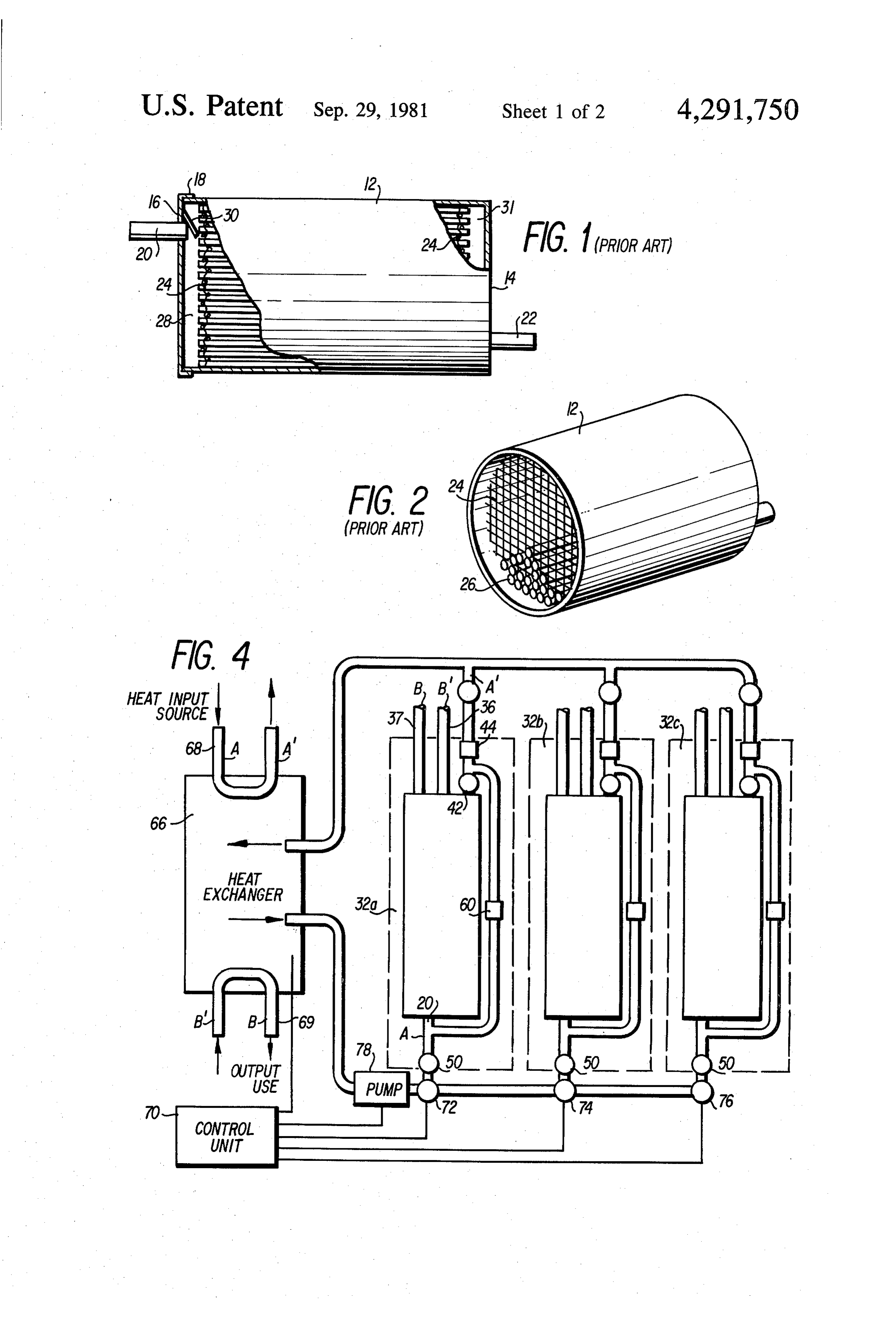
they become frozen) which is taken out of the system at FIG. 1 is a side view, partially broken away, of a the heat exchanger. prior-art heat storage unit of a type used in this inven A limitation of this prior-art system is that heat en tion;
ergy cannot be discharged from the system at several 30 FIG. 2 is an isometric view of the heat storage unit of selected predetermined temperatures simultaneously. FIG. 1, partially filled with containers (cells) and with That is, the system only allows the extraction of one an end closure being removed;
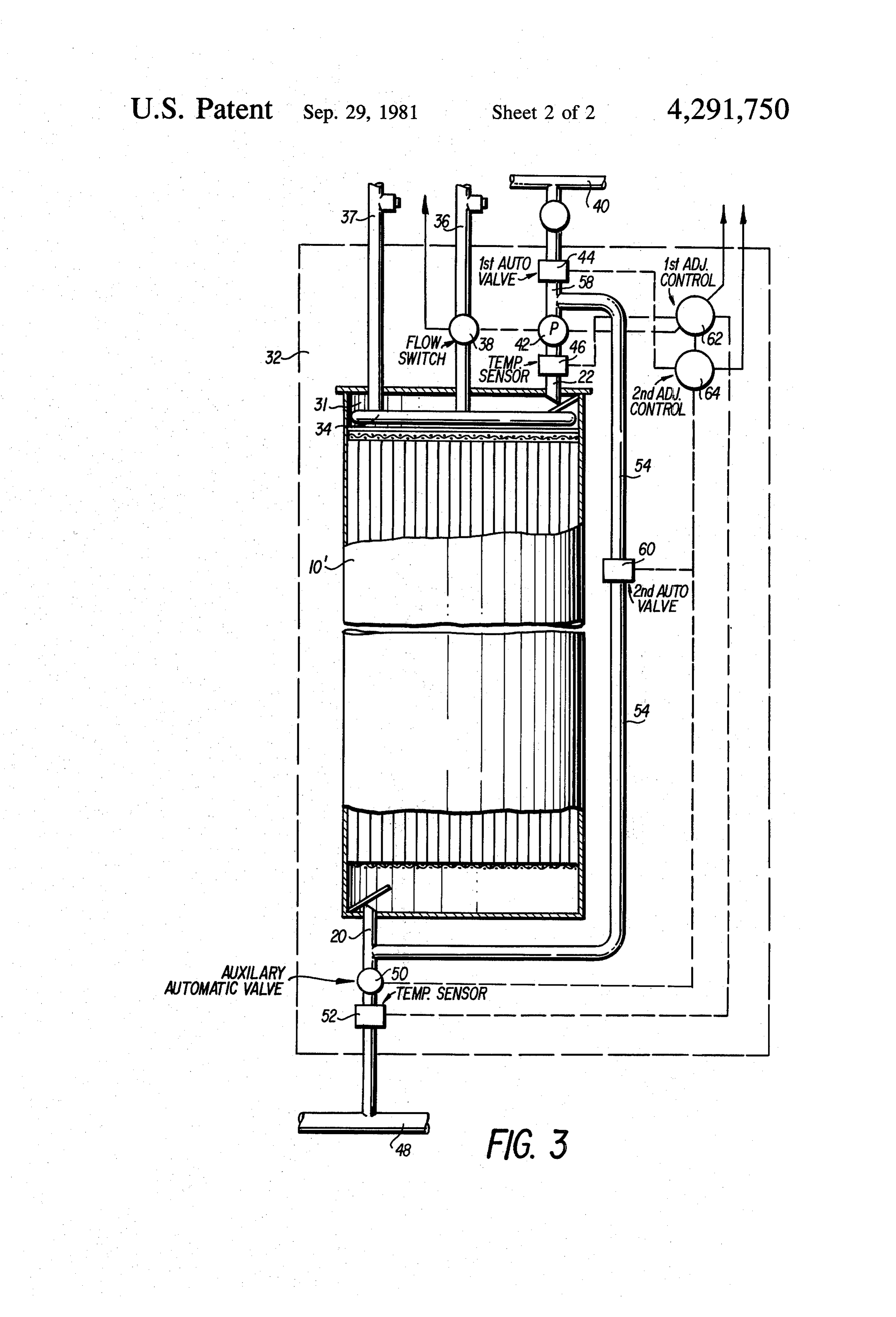
temperature heat energy at a time. Thus, it is an object FIG. 3 is a schematic diagram of a heat storage as of this invention to provide a heat storage system which sembly of this invention employing a modified heat allows the discharge of heat at several temperatures 35 storage unit; and simultaneously. FIG. 4 is a schematic diagram of a heat storage sys Another limitation of the above described system is tem combining several of the heat storage assemblies of that during periods when high temperature fluid is FIG. 3.
available from solar sources, or waste sources, one can not necessarily store this energy at the high temperature 40 DESCRIPTION OF PREFERRED in a high temperature unit. This is because heat may also EMBODIMENTS OF THE INVENTION be required to be simultaneously discharged from the The basic heat storage unit of the general type used in system causing the total fluid temperature to be re this invention (shown in FIGS. 1 and 2) is described in duced. Thus, it is an object of this invention to provide greater detail in U.S. Pat. No. 4,127,161 to Clyne et al. a system which allows an available high temperature 45 It comprises a cylindrical housing 12 having a sealed charging fluid to charge a high-temperature unit while end 14 and a removable end closure 16. When in use, the simultaneously allowing another unit of the system to end closure 16 is mounted to the cylinder 12 by fasten be discharged. ers 18. To prevent leakage of heat transfer fluid, a gas Still another limitation of the prior art was that the ket is used between the closure 16 and cylinder 12. A various heat storage assemblies could only be used with 50 fluid flow inlet pipe 20 is fixed to the end closure 16 and an external heat exchanger thus lowering the efficiency an outlet pipe 22 is fixed to end plate 14. and increasing the expense of the system when only one A planar support member, shown as screen 24 in heat storage assembly is used. It is therefore another FIG. 2, is provided adjacent and parallel to each end object of this invention to provide a heat storage assem plate of the assembly. These screens are fixed within the bly which does not require an external heat. exchanger 55 cylinder for supporting heat storage containers or cells for the charging and discharging thereof. 26. These containers or cells 26 are in the form of closed It is still another object of this invention to provide a tubes., The tubes are individually removable from the heat storage assembly which can be used in a parallel assembly and an access plug is provided at one end of system, or which can be used alone advantageously. each tube so that a heat storage substance contained Finally, it is an object of this invention to provided a 60 therein can be easily replaced. fusion-type heat storage assembly which can be eco Referring to FIG. 1, when in use a heat transfer fluid nomically manufactured and which is efficient in opera will be directed from an inlet pipe 20 into an entrance tOn. space 28 by a fluid flow deflector 30. Deflector 30 has SUMMARY OF THE INVENTION holes therein so that while some fluid is deflected down 65 wardly, other fluid is diffused into the space above the
According to principles of this invention, a fusion deflector. The fluid will then pass through the screen type heat storage assembly includes a fusion-type heat 24, flow around the heat storage tubes 26, and into an storage unit connected in parallel with a fluid circulat exit space. 31 toward outlet pipe 22. The screens 24
Page 5
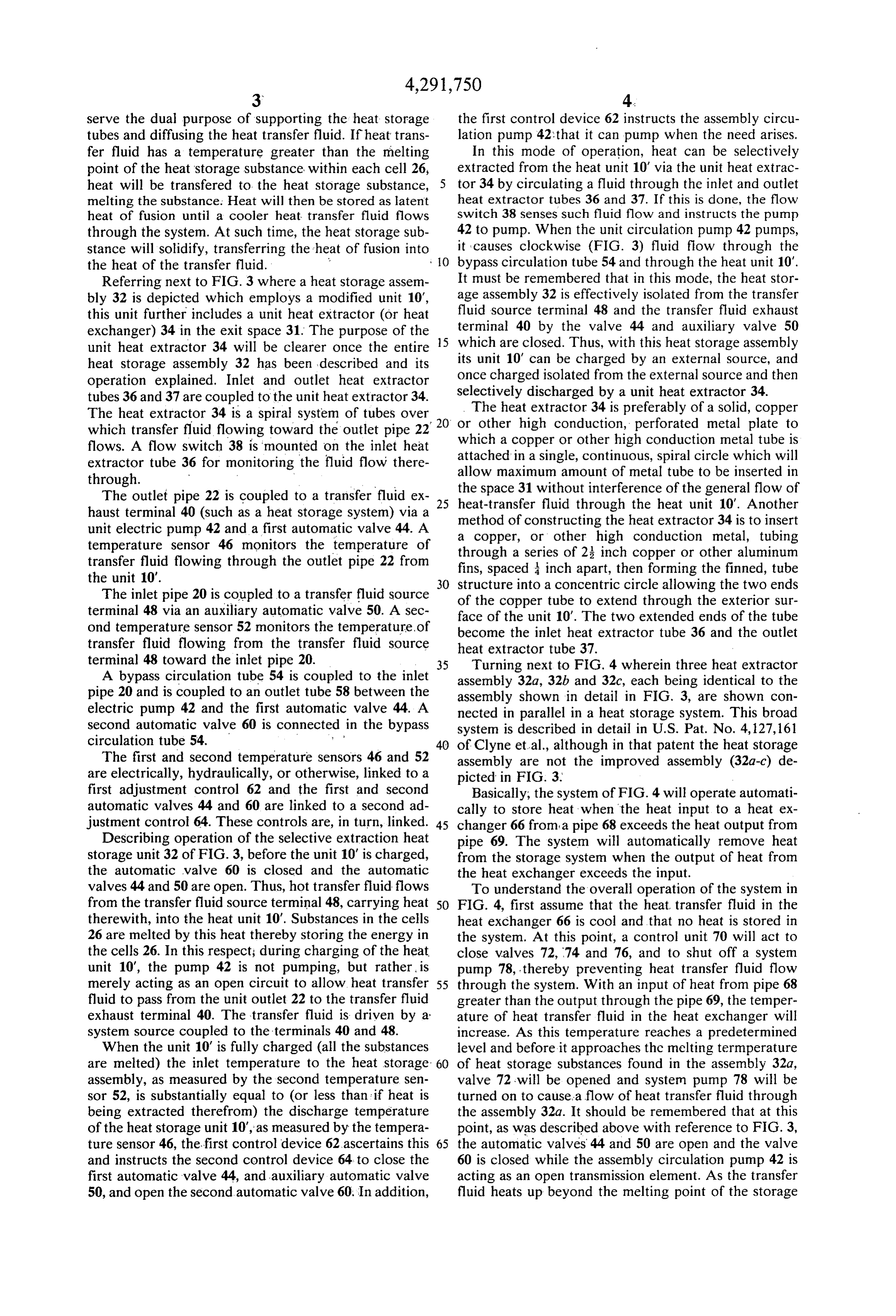
serve the dual purpose of supporting the heat storage the first control device 62 instructs the assembly circu tubes and diffusing the heat transfer fluid. If heat trans lation pump 42 that it can pump when the need arises. fer fluid has a temperature greater than the melting In this mode of operation, heat can be selectively point of the heat storage substance within each cell 26, extracted from the heat unit 10" via the unit heat extrac heat will be transfered to the heat storage substance, tor 34 by circulating a fluid through the inlet and outlet melting the substance: Heat will then be stored as latent heat extractor tubes 36 and 37. If this is done, the flow heat of fusion until a cooler heat transfer fluid flows switch 38 senses such fluid flow and instructs the pump through the system. At such time, the heat storage sub 42 to pump. When the unit circulation pump 42 pumps, stance will solidify, transferring the heat of fusion into it causes clockwise (FIG. 3) fluid flow through the the heat of the transfer fluid. . O bypass circulation tube 54 and through the heat unit 10". Referring next to FIG. 3 where a heat storage assem It must be remembered that in this mode, the heat stor bly 32 is depicted which employs a modified unit 10", age assembly 32 is effectively isolated from the transfer this unit further includes a unit heat extractor (or heat fluid source terminal 48 and the transfer fluid exhaust exchanger) 34 in the exit space 31. The purpose of the 5 terminal 40 by the valve 44 and auxiliary valve 50 unit heat extractor 34 will be clearer once the entire which are closed. Thus, with this heat storage assembly heat storage assembly 32 has been described and its its unit 10" can be charged by an external source, and operation explained. Inlet and outlet heat extractor once charged isolated from the external source and then tubes 36 and 37 are coupled to the unit heat extractor 34. selectively
The heat discharged by a unit heat extractor 34.
extractor 34 is preferably of a solid, copper
The heat extractor 34 is a spiral system of tubes over • 20 or other high which transfer fluid flowing toward the outlet pipe 22 which a copperconduction, or other high perforated metal plate to conduction metal tube is flows. A flow switch 38 is mounted on the inlet heat extractor tube 36 for monitoring the fluid flow there attached in a single, continuous, spiral circle which will allow maximum amount of metal tube to be inserted in
The outlet pipe 22 is coupled to a transfer fluid ex 25 the space 31 without interference of the general flow of heat-transfer fluid through the heat unit 10'. Another haust terminal 40 (such as a heat storage system) via a method of constructing the heat extractor 34 is to insert unit electric pump 42 and a first automatic valve 44. A a copper, or other high conduction metal, tubing temperature sensor 46 monitors the temperature of through a series of 2 inch copper or other aluminum transfer fluid flowing through the outlet pipe 22 from fins, spaced inch apart, then forming the finned, tube the unit 10'.
The inlet pipe 20 is coupled to a transfer fluid source structure into a concentric circle allowing the two ends terminal 48 via an auxiliary automatic valve 50. A sec face of the unittube of the copper to extend through the exterior sur 10'. The two extended ends of the tube ond temperature sensor 52 monitors the temperature, of become the inlet heat extractor tube 36 and the outlet transfer fluid flowing from the transfer fluid source heat extractor tube 37.
terminal 48 toward the inlet pipe 20. 35 Turning next to FIG. 4 wherein three heat extractor A bypass circulation tube 54 is coupled to the inlet assembly 32a, 32b and 32c, each being identical to the pipe 20 and is coupled to an outlet tube 58 between the assembly shown in detail in FIG. 3, are shown con electric pump 42 and the first automatic valve 44. A nected in parallel in a heat storage system. This broad second automatic valve 60 is connected in the bypass system is described in detail in U.S. Pat. No. 4,127, 161 circulation tube 54. 40 of Clyne et al., although in that patent the heat storage The first and second temperature sensors 46 and 52 assembly are not the improved assembly (32a-c) de are electrically, hydraulically, or otherwise, linked to a picted in FIG. 3.
first adjustment control 62 and the first and second Basically, the system of FIG. 4 will operate automati automatic valves 44 and 60 are linked to a second ad cally to store heat when the heat input to a heat ex justment control 64. These controls are, in turn, linked. 45 changer 66 from a pipe 68 exceeds the heat output from Describing operation of the selective extraction heat pipe 69. The system will automatically remove heat storage unit 32 of FIG. 3, before the unit 10' is charged, from the storage system when the output of heat from the automatic valve 60 is closed and the automatic the heat exchanger exceeds the input. valves 44 and 50 are open. Thus, hot transfer fluid flows To understand the overall operation of the system in from the transfer fluid source terminal 48, carrying heat 50 FIG. 4, first assume that the heat transfer fluid in the therewith, into the heat unit 10'. Substances in the cells heat exchanger 66 is cool and that no heat is stored in 26 are melted by this heat thereby storing the energy in the system. At this point, a control unit 70 will act to the cells 26. In this respect; during charging of the heat close valves 72, 74 and 76, and to shut off a system unit 10", the pump 42 is not pumping, but rather, is pump 78, thereby preventing heat transfer fluid flow merely acting as an open circuit to allow heat transfer 55 through the system. With an input of heat from pipe 68 fluid to pass from the unit outlet 22 to the transfer fluid greater than the output through the pipe 69, the temper exhaust terminal 40. The transfer fluid is driven by a ature of heat transfer fluid in the heat exchanger will system source coupled to the terminals 40 and 48. increase. As this temperature reaches a predetermined When the unit 10' is fully charged (all the substances level and before it approaches the melting termperature are melted) the inlet temperature to the heat storage 60 of heat storage substances found in the assembly 32a, assembly, as measured by the second temperature sen valve 72 will be opened and system pump 78 will be sor 52, is substantially equal to (or less than if heat is turned on to causea flow of heat transfer fluid through being extracted therefrom) the discharge temperature the assembly 32a. It should be remembered that at this of the heat storage unit 10", as measured by the tempera point, as was described above with reference to FIG. 3, ture sensor 46, the first control device 62 ascertains this 65 the automatic valves 44 and 50 are open and the valve and instructs the second control device 64 to close the 60 is closed while the assembly circulation pump 42 is first automatic valve 44, and auxiliary automatic valve acting as an open transmission element. As the transfer 50, and open the second automatic valve 60. In addition, fluid heats up beyond the melting point of the storage
Page 6
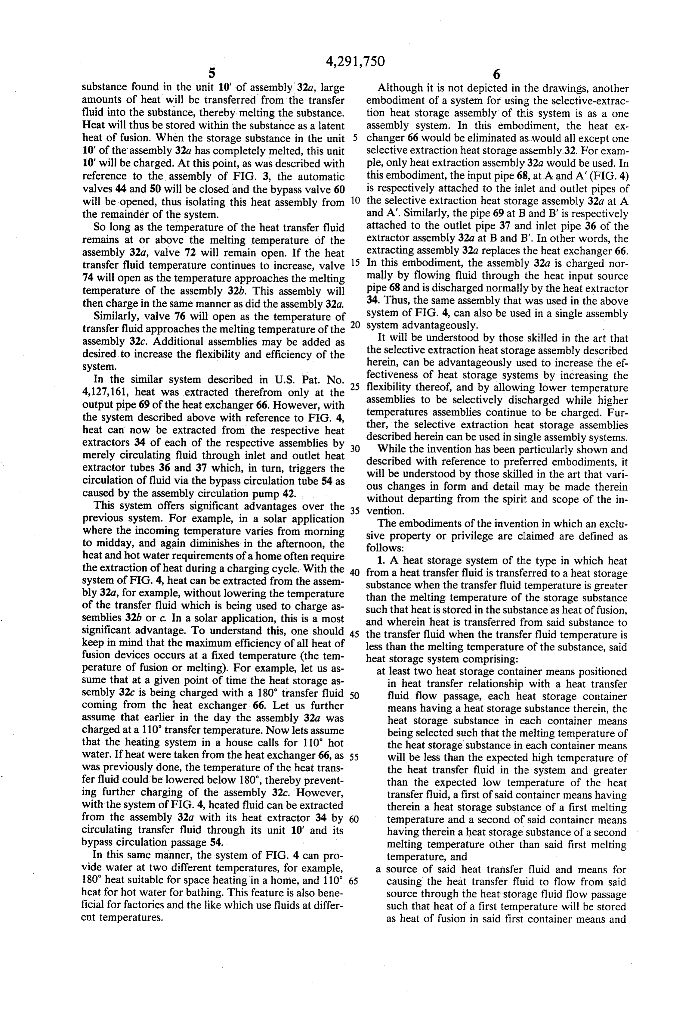
substance found in the unit 10' of assembly 32a, large Although it is not depicted in the drawings, another amounts of heat will be transferred from the transfer embodiment of a system for using the selective-extrac fluid into the substance, thereby melting the substance. tion heat storage assembly of this system is as a one Heat will thus be stored within the substance as a latent assembly system. In this embodiment, the heat ex heat of fusion. When the storage substance in the unit changer 66 would be eliminated as would all except one 10' of the assembly 32a has completely melted, this unit selective extraction heat storage assembly 32. For exam 10' will be charged. At this point, as was described with ple, only heat extraction assembly 32a would be used. In reference to the assembly of FIG. 3, the automatic this embodiment, the input pipe 68, at A and A' (FIG. 4) valves 44 and 50 will be closed and the bypass valve 60 is respectively attached to the inlet and outlet pipes of will be opened, thus isolating this heat assembly from 10 the selective extraction heat storage assembly 32a at A the remainder of the system. and A'. Similarly, the pipe 69 at B and B' is respectively So long as the temperature of the heat transfer fluid attached to the outlet pipe 37 and inlet pipe 36 of the remains at or above the melting temperature of the extractor assembly 32a at B and B'. In other words, the assembly 32a, valve 72 will remain open. If the heat 15 extracting assembly 32a replaces the heat exchanger 66. transfer fluid temperature continues to increase, valve In this embodiment, the assembly 32a is charged nor 74 will open as the temperature approaches the melting mally by flowing fluid through the heat input source temperature of the assembly 32b. This assembly will pipe 68 and is discharged normally by the heat extractor then charge in the same manner as did the assembly 32a. 34. Thus, the same assembly that was used in the above Similarly, valve 76 will open as the temperature of system of FIG. 4, can also be used in a single assembly transfer fluid approaches the melting temperature of the 0 system advantageously.
assembly 32c. Additional assemblies may be added as It will be understood by those skilled in the art that the selective extraction heat storage assembly described desired to increase the flexibility and efficiency of the herein, system. can be advantageously used to increase the ef In the similar system described in U.S. Pat. No. 25 fectiveness flexibility of heat storage systems by increasing the thereof, and by allowing lower temperature 4,127,161, heat was extracted therefrom only at the output pipe 69 of the heat exchanger 66. However, with assemblies to be selectively discharged while higher the system described above with reference to FIG. 4, temperatures assemblies continue to be charged. Fur heat can now be extracted from the respective heat ther, the selective extraction heat storage assemblies extractors 34 of each of the respective assemblies by 30 described herein can be used in single assembly systems. While the invention has been particularly shown and merely circulating fluid through inlet and outlet heat described with reference to preferred embodiments, it extractor tubes 36 and 37 which, in turn, triggers the will be understood by those skilled in the art that vari circulation of fluid via the bypass circulation tube 54 as ous changes in form and detail may be made therein caused by the assembly circulation pump 42.
This system offers significant advantages over the without departing from the spirit and scope of the in previous system. For example, in a solar application 35 vention.
where the incoming temperature varies from morning siveTheproperty embodiments of the invention in which an exclu or privilege are claimed are defined as to midday, and again diminishes in the afternoon, the follows:
heat and hot water requirements of a home often require 1. A heat storage system of the type in which heat the extraction of heat during a charging cycle. With the 40 from a heat transfer fluid is transferred to a heat storage system of FIG. 4, heat can be extracted from the assem substance when the transfer fluid temperature is greater bly 32a, for example, without lowering the temperature than the melting temperature of the storage substance of the transfer fluid which is being used to charge as such that heat is stored in the substance as heat of fusion, semblies 32b or c. In a solar application, this is a most and wherein heat is transferred from said substance to significant advantage. To understand this, one should 45 the transfer fluid when the transfer fluid temperature is keep in mind that the maximum efficiency of all heat of less than the melting temperature of the substance, said fusion devices occurs at a fixed temperature (the tem heat storage system comprising:
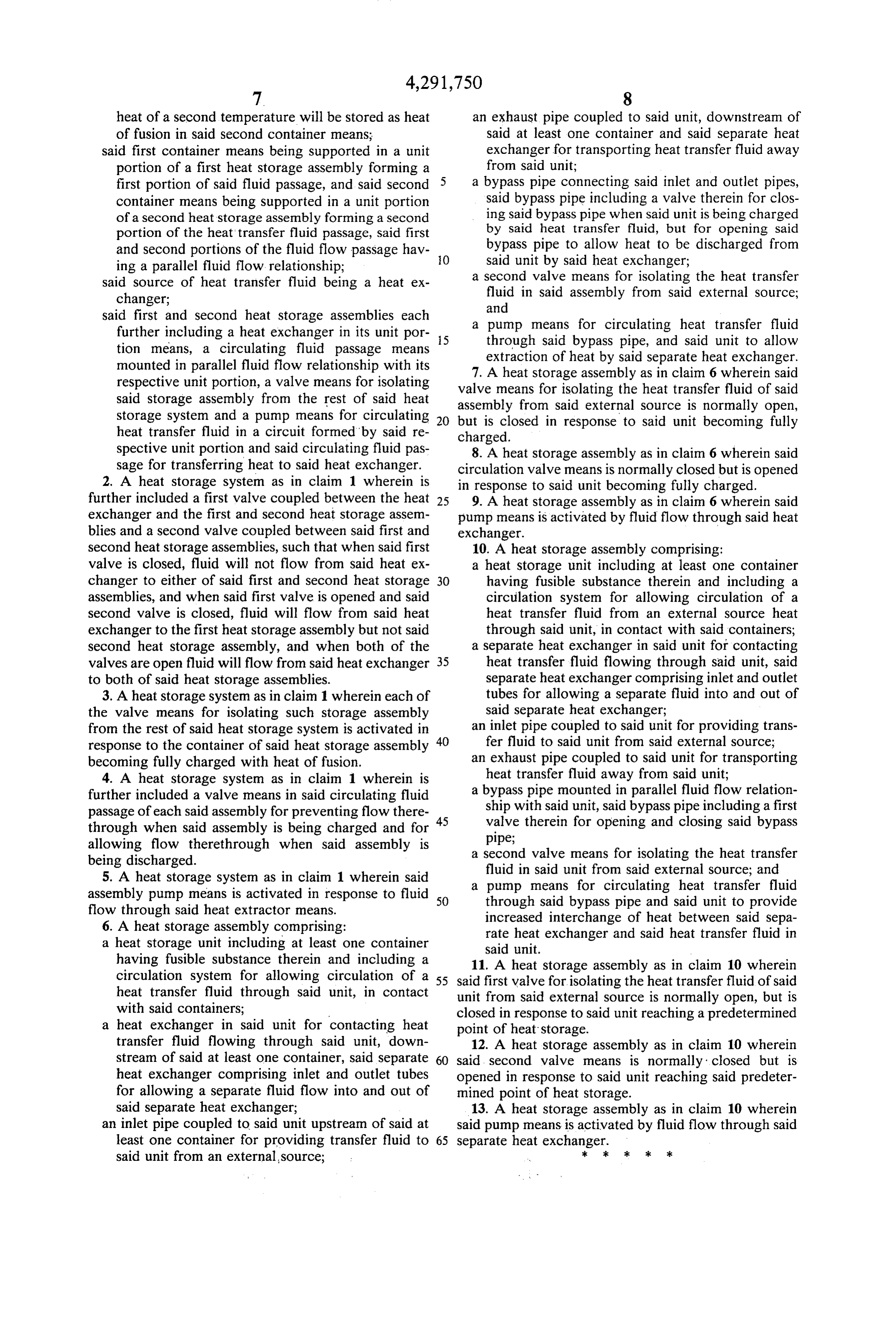
perature of fusion or melting). For example, let us as at least two heat storage container means positioned sume that at a given point of time the heat storage as in heat transfer relationship with a heat transfer sembly 32c is being charged with a 180 transfer fluid 50 fluid flow passage, each heat storage container coming from the heat exchanger 66. Let us further means having a heat storage substance therein, the assume that earlier in the day the assembly 32a was heat storage substance in each container means charged at a 110 transfer temperature. Now lets assume being selected such that the melting temperature of that the heating system in a house calls for 110” hot the heat storage substance in each container means water. If heat were taken from the heat exchanger 66, as 55 will be less than the expected high temperature of was previously done, the temperature of the heat trans the heat transfer fluid in the system and greater fer fluid could be lowered below 180, thereby prevent than the expected low temperature of the heat ing further charging of the assembly 32c. However, transfer fluid, a first of said container means having with the system of FIG. 4, heated fluid can be extracted therein a heat storage substance of a first melting from the assembly 32a with its heat extractor 34 by 60 temperature and a second of said container means circulating transfer fluid through its unit 10' and its having therein a heat storage substance of a second bypass circulation passage 54. melting temperature other than said first melting In this same manner, the system of FIG. 4 can pro temperature, and vide water at two different temperatures, for example, a source of said heat transfer fluid and means for 180 heat suitable for space heating in a home, and 110 65 causing the heat transfer fluid to flow from said heat for hot water for bathing. This feature is also bene source through the heat storage fluid flow passage ficial for factories and the like which use fluids at differ such that heat of a first temperature will be stored ent temperatures. as heat of fusion in said first container means and
Page 7
heat of a second temperature will be stored as heat an exhaust pipe coupled to said unit, downstream of of fusion in said second container means; said at least one container and said separate heat said first container means being supported in a unit exchanger for transporting heat transfer fluid away portion of a first heat storage assembly forming a from said unit;
first portion of said fluid passage, and said second 5 a bypass pipe connecting said inlet and outlet pipes, container means being supported in a unit portion said bypass pipe including a valve therein for clos of a second heat storage assembly forming a second ing said bypass pipe when said unit is being charged portion of the heat transfer fluid passage, said first by said heat transfer fluid, but for opening said and second portions of the fluid flow passage hav O bypass pipe to allow heat to be discharged from ing a parallel fluid flow. relationship; said unit by said heat exchanger; said source of heat transfer fluid being a heat ex a second valve means for isolating the heat transfer changer; fluid in said assembly from said external source; and said first and second heat storage assemblies each a pump means for circulating heat transfer fluid further including a heat exchanger in its unit por 5. through said bypass pipe, and said unit to allow tion means, a circulating fluid passage means extraction of heat by said separate heat exchanger. mounted in parallel fluid flow relationship with its 7. A heat storage assembly as in claim 6 wherein said respective unit portion, a valve means for isolating valve means for isolating the heat transfer fluid of said said storage assembly from the rest of said heat assembly from said external source is normally open, storage system and a pump means for circulating but is closed in response to said unit becoming fully heat transfer fluid in a circuit formed by said re charged.
spective unit portion and said circulating fluid pas 8. A heat storage assembly as in claim 6 wherein said sage for transferring heat to said heat exchanger. circulation valve means is normally closed but is opened 2. A heat storage system as in claim 1 wherein is in response to said unit becoming fully charged. further included a first valve coupled between the heat 25 9. A heat storage assembly as in claim 6 wherein said exchanger and the first and second heat storage assem pump means is activated by fluid flow through said heat blies and a second valve coupled between said first and exchanger.
second heat storage assemblies, such that when said first 10. A heat storage assembly comprising: valve is closed, fluid will not flow from said heat ex a heat storage unit including at least one container changer to either of said first and second heat storage 30 having fusible substance therein and including a assemblies, and when said first valve is opened and said circulation system for allowing circulation of a second valve is closed, fluid will flow from said heat heat transfer fluid from an external source heat exchanger to the first heat storage assembly but not said through said unit, in contact with said containers; second heat storage assembly, and when both of the a separate heat exchanger in said unit for contacting valves are open fluid will flow from said heat exchanger 35 heat transfer fluid flowing through said unit, said to both of said heat storage assemblies. separate heat exchanger comprising inlet and outlet 3. A heat storage system as in claim 1 wherein each of tubes for allowing a separate fluid into and out of the valve means for isolating such storage assembly said separate heat exchanger; from the rest of said heat storage system is activated in an inlet pipe coupled to said unit for providing trans response to the container of said heat storage assembly 40 fer fluid to said unit from said external source; becoming fully charged with heat of fusion. an exhaust pipe coupled to said unit for transporting 4. A heat storage system as in claim 1 wherein is heat transfer fluid away from said unit; further included a valve means in said circulating fluid a bypass pipe mounted in parallel fluid flow relation passage of each said assembly for preventing flow there ship with said unit, said bypass pipe including a first through when said assembly is being charged and for 45 valve therein for opening and closing said bypass allowing flow therethrough when said assembly is pipe;
being discharged. a second valve means for isolating the heat transfer 5. A heat storage system as in claim 1 wherein said fluid in said unit from said external source; and assembly pump means is activated in response to fluid 50 a pump means for circulating heat transfer fluid flow through said heat extractor means. through said bypass pipe and said unit to provide 6. A heat storage assembly comprising: increased interchange of heat between said sepa a heat storage unit including at least one container rate heat exchanger and said heat transfer fluid in said unit.
having fusible substance therein and including a 11. A heat storage assembly as in claim 10 wherein circulation system for allowing circulation of a 55 said first valve for isolating the heat transfer fluid of said heat transfer fluid through said unit, in contact unit from said external source is normally open, but is with said containers; closed in response to said unit reaching a predetermined a heat exchanger in said unit for contacting heat point of heat storage.
transfer fluid flowing through said unit, down 12. A heat storage assembly as in claim 10 wherein stream of said at least one container, said separate 60 said, second valve means is normally closed but is heat exchanger comprising inlet and outlet tubes opened in response to said unit reaching said predeter for allowing a separate fluid flow into and out of mined point of heat storage.
said separate heat exchanger; 13. A heat storage assembly as in claim 10 wherein an inlet pipe coupled to said unit upstream of said at said pump means is activated by fluid flow through said least one container for providing transfer fluid to 65 separate heat exchanger.
said unit from an external, source;
Page 8
UNITED STATES PATENT AND TRADEMARK OFFICE
CERTIFICATE OF CORRECTION
INVENTOR(S) : Arthur J. Clyne et al.
it is Certified that error appears in the above-identified patent and that said Letters Patent is hereby corrected as shown below:
Column 3, line 34, add a hyphen between "transfer" and "fluid". Column 4, line 36, change "assembly" to -- assemblies -- ; and line 4l, change both printings of "assembly" to
Column 8, line 32, "heat" should be placed before "source", line 37, insert --flow -- between "fluid" and "into ". signed and scaled this
Twenty-third Day of March 1982
GERALD.J. MOSSENGHOFF
Attesting Officer Commissioner of Patents and Trademarks
Provenance
- Collection
- Cited prior art
- Original PDF
- patentimages.storage.googleapis.com →
- Filed
- 1980-07-29
- Pages
- 8
- Method
- pdftotext (the PDF's own text layer) + pdftoppm 300dpi page scans
- Source
- Google Patents bibliographic record
- Granted
- 1981-09-29
- Inventors
- Arthur J. Clyne; John E. Knarr; Stanley Miller; Energy Recycling Co
- Transcribed from
- patentimages.storage.googleapis.com →