patent · US4276440
Thermoelectric generator operating with a cooling device for converting solar energy into electric energy, and system for the use thereof
30 June 1981
Page 1 — bibliographic record
United States Patent (19) 11 4,276,440 Cannelli 45) Jun. 30, 1981 54) THERMOELECTRIC GENERATOR 1,526,641 2/1925 Mulvany et al. ................ 136/224 x OPERATING WITH A COOLING DEVICE 3,794,527 2/1974 Kim ...................................... 136/208 FOR CONVERTNG SOLAR ENERGY INTO Primary Examiner-Leland A. Sebastian ELECTRICENERGY, AND SYSTEM FOR Attorney, Agent, or Firm-McAulay, Fields, Fisher, THE USE THEREOF Goldstein & Nissen 76 Inventor: Pierino Cannelli, Via Fontanellato, 57 ABSTRACT 52, Rome, Italy A generator of electric energy by the transformation o (21) Appl. No.: 27,908 thermal, solar energy, or of heat of any source, consist 22 Filed: Apr. 6, 1979 ing in one or more thermocouples combined with a cooling device, cooling down the weldings of the ther 30 Foreign Application Priority Data mocouples on which heat is produced by the Peltie! Apr. 7, 1978 IT Italy ............................... 48789 A/78 effect, also producing a very high thermal gradient. The Jan. 11, 1979 IT Italy ....... ... 47589 A/79 cooling device exploits, for the functioning thereof, the Feb. 1, 1979 IT Italy ........... ... 47851 A/79 phenomena which can be observed along the thermo couples. The system for the use of such a generato) 51) Int. Cl. ............................................. H01L 35/00 provides a particular disposition of the same in para 52 U.S. C. .................................... 136/206; 136/204; bolic collectors, as to increase the sun ray concentration 136/208; 136/224 onto the weldings exposed to the heat and as to allow :
58 Field of Search ................ 136/204, 206, 208, 224 decentralization in the electric energy supply by mean: 56 References Cited of a plurality of generators consisting in only one ther mocouple, said generators being interconnected.
1,506,962 9/1924 Andrews .......................... 136/224 X 12 Claims, 8 Drawing Figures
Page 2
Drawing sheet — no readable text.
Page 3
Drawing sheet — no readable text.
Page 4
Drawing sheet — no readable text.
Page 5
Drawing sheet — no readable text.
Page 6
Drawing sheet — no readable text.
Page 7
Said task is solved realizing an electric energy gener
THERMOELECTRIC GENERATOR OPERATING ator consisting of one or more thermocouples made WITH A COOLING DEVICE FOR CONVERTNG from metals with electrical and mechanical features SOLAR ENERGY INTO ELECTRICENERGY, AND which are the most appropriate for the purpose, com SYSTEM FOR THE USE THEREOF bined with an adsorption cooling device, fed by the same heat supplied along the thermocouple(s) used, and
The present invention concerns a generator of electri said cooling device acting onto said welding of the cal energy by the conversion of thermal, solar energy or thermocouple(s) on which, by the Peltier effect, heat is of any other appropriate heat source, consisting in one developed, as to reduce there the temperature of a maxi or more thermocouples combined with an absorption 10 mum and therefore keep the thermal gradient between cooling device acting on one of the weldings of the the hot and the cold weldings of the thermocouple(s) at thermocouples, said cooling device being fed exploiting a high level, thus obtaining a high value of generated the same heat produced along the thermocouple(s) e.m.f. and, consequently, a high value of the power. used. Therefore, according to one of the main principles of It is well known how urgent the problem is to find 15 the present invention, the heat developed on that weld new energy sources, and it is also well known how ing of the thermocouple(s) used on which heat develops many experiments have been made, and the many re by the Peltier effect, is reduced of a maximum. In fact, searches that have been performed looking to exploit, as a consequence of the Peltier effect, on said weldings most of all, the solar energy, to convert the same into a heat is developed which, after some time, tends to electric energy. 20 reach the values of the heat supplied from the outside The experiments performed until now have brought from the other welding of the thermocouple, so that the to two fundamental systems for converting solar energy thermoelectric effect would be annulled. This inconve into electric energy. nience is completely eliminated by the combination of The first kind consists in a system which picks up the the thermocouples with the absorption cooling device, sun rays, stores the thermal energy thereof, transform 25 which has furthermore the possibility of highering the ing the sun rays into mechanical energy and, succes thermal gradient between the cool and the hot weldings sively, into electric energy. This kind of system is of the thermocouples, increasing the efficiency of the adapted for the production of an energy of medium or electric energy generator, thus realized. great power, and requires a vast ground extension so as Another fundamental principle of the present inven to provide for a pick up of a sufficient quantity of sun 30 tion is the one of feeding the absorption cooling device rays. Consequently, beyond the machinery used, said exploiting the same heat supplied along the thermocou system requires much personnel for the conduction and ples.
the maintenance thereof. For its own nature, this kind of According to the present invention, a plurality of system can provide a satisfying efficiency only if it is of thermocouples are connected by welding in alternate remarkable dimensions. Consequently, the necessity to 35 succession of the component metals, as to assume a feed many users by one and the same system, consists in spiral-like disposition. In that spiral-like disposition, the the conventional loss of electric energy by transforma welding zone of one couple of elements will always be tion, transport and distribution. opposite to the immediately successive welding, i.e. the The second kind of such systems, which have been weldings to be exposed to the heat are always aligned until now the object of many experiments, converts the 40 oppositely to the weldings to be cooled down. Further solar radiations directly into electric energy, exploiting more, according to the present invention, the hot weld the principle of the photovoltaic cells. This kind of ing zones are blackened and placed into apposite, single system may be realized in smaller dimensions and does containers out of insulating and refractory material, not request a high cost of personnel for the conduction resistant to the smelting temperatures of the alloys of thereof. Furthermore, for the dimensions thereof, it can 45 said weldings.
also be employed for single, small users and therefore Always according to the present invention, the four allow a decentralization in the electric energy supply. principal elements forming the cooling device are ap Nonetheless, the realization thereof is, even with the plied to the thermocouples as follows: The first element, same power rate, more expensive than the first kind of i.e. the boiler, is applied immediately below the welding system discussed hereinabove. 50 zones to be exposed to the heat, as to be crossed by the From that which is described above it appears evi elements of the one and the other metal of the thermo dent that the experiments until now preformed to obtain couples.
electric energy which electric energy is, derived from The second element, i.e. the condenser, is applied solar energy, do not allow the practical actuation and astride of the elements of one and the same metal of the the diffusion of the proposed systems as these are too 55 thermocouples.
expensive. The third element, i.e. the absorber, is applied astride It is therefore a task of the present invention to pro of the elements of the thermocouples consisting in the pose a kind of system, the realization and conduction other metal.
costs thereof providing for a widespread practical appli The fourth element, i.e. the refrigerator, is applied cation, and which is simple in the realization and does opposite to the boiler, as to be crossed by the elements not require any machinery of expensive maintenance. of the one and the other metal of the thermocouples and Therefore, the system does not involve personnel costs, to contain all the welding zones which are to be cooled and it is of such reduced dimensions that even assuring down.
an optimal efficiency, the system permits a decentraliza Said four elements are evidently interconnected by tion of the electric energy supply, thus furthermore 65 means of a tubing which allows the flowing of the cool assuring a higher efficiency for the single users, as the ing fluid of the cycle.
single user is no longer dependent on a single supply According to the present invention, the elements of SOC2. the thermocouples crossing the boiler, the condensor
Page 8
and the absorber of the cooling device are appropriately According to another embodiment of the present finned as to facilitate the heat exchange, invention, which can be considered as a real variant of As has already been said, the cooling device, already the same, single generators are used provided with only known, applied to the thermocouples series, is operated, one thermocouple, to be considered as real modular according to the present invention, by the same phe unities of an assembly consisting in a plurality of such nomena which can be observed along said thermocou unities. Each one of said unities will work with a sun ray ples. In fact, the cooling fluid which is found inside the concentration, smaller that the one of the before men boiler, will be heated up to the boiling point by the heat tioned embodiment and, therefore, at a lower tempera immediately supplied, downstream of the welding ture. Taking into consideration the simpler realization, zones exposed to the heat. The evaporated fluid passes, 10 this second embodiment will result to be cheaper in the under pression, into the condensor in the form of gas, realization thereof; the lower cost is also due to the and in the condensor heat will be substracted from the possibility of making use of cheaper material for the gas by the Thompson effect, which, along that section realization, in consideration of the lower temperature at of the thermocouples, can be observed in the form of 15 which In it is working.
this embodiment the thermocouple of each single heat absorbing. The gas thus cooled down enters the cooling device where it suddenly expands and thus modular is realized in such a way that the zone to be produces the desired cold onto the welding zones con ent exposed to the heat consists in two this sheets of differ tained therein. Then the gas goes up again towards the as amaterials, the one welded onto the other and wound boiler crossing the absorber, wherein heat is now given 20 ing the shape of athecylinder spiral around boiler of the cooling device, hav and appropriately placed in, exploiting the Thompson effect, which, along that along the focus area of a parabolic-cylindrical collector, section of the thermocouples, can be observed in the and the welding zone to be cooled down consisting in form of heat production. two this sheets of the same materials of the first welding Finally it is to be noted that the end of the first ele ment of the forst thermocouple and the end of the last 25 zone, welded one onto the other, and wound like a element of the last thermocouple are connected to a same being ofthe spiral around refrigerator of the cooling device, the cylindrical shape and placed opposite of convertor, which transforms the direct current thus the convex part of said cylindrical paraboloid, i.e. in the obtained into alternate current to be put on the distribu shadow area with respect of the sun rays, the condensor tion network. and the absorber being placed parallel between the The electric energy generator thus realized can be, in 30 boiler and the refrigerator and being interconnected and general, applied, according to the present invention, to connected to the same by a feeding tubing in the cycle different kinds of systems adapted to obtain the sun ray of the cold fluid.
concentration along the welding zones of the thermo The condensor and the absorber are, in this case, couples to be exposed to the heat. In the following two appropriately finned and the functioning thereof does preferred embodiments of said systems will be de 35 not depend, as in the already described generator, from scribed. the heat given in or supplied, by the Thompson effect, The first preferred embodiment according to the from the relative sections of the thermoelectric couples, present invention provides the installation of a plurality but from the simple heat exchange with the outside. of generators as above described disposed in dial to the The two different metal sheets out of which the hot axis of a paraboloid provided with a specular surface, 40 weldings consist, are appropriately blackened to favour already known. The generators are placed in such a the heat absorption. Furthermore, the same sheets, way that the welding zones to be exposed to the heat of wound around the boiler of the cooling device are the sun rays will be found on the focus area of the parab placed, together with said boiler, in a vacuum inside a oloid, while the welding zones which are to be cooled quartz or pirex tube, as to avoid heat dispersion. The down are found beyond the convex area of the parabo 45 two different metal sheets forming the cold weldings loid, i.e. in a shadow area for the sun rays. wound around the refrigerator, are in turn contained, As to obtain a major concentration of the sun rays on together with the refrigerator, within a tubolar element the welding zones of the thermocouples to be exposed out of insulating material.
to the heat, above said zones a parabolic cap is pro The connection between the hot and cold welding vided, the concave area thereof being turned towards 50 zone is realized by a crossing of one modular unity and the concave area of said first paraboloid. The sun rays the successive one, i.e. those thermocouple elements picked up by the first paraboloid are therefore further which are out of the same material are interconnected concentrated by said second parabolic cap, reflecting between hot weldings of one modular unity and cold the same directly onto the whole welding zone to be weldings of the successive modular unity. This kind of heated up. Above said hot weldings, an already well 55 connection causes the Thompson effects, which reveal known honeycomb structure is provided consisting in a in the form of giving in, respectively of absorbing of plurality of small glass cylinders, as to avoid a heat heat along the connecting elements of different mate dispersion due to re-irradiation or to connection. The rial, achieve a thermal balance. For this purpose it is single generators are connected between themselves, preferred that the connection conductors be concentri and the functioning thereof is completely the one above 60 cally placed one to the other, as well as distanced by described. The end of the first element of the first ther insulating material.
mocouple and the last element of the last thermocouple Also in this case a parallel and/or series connection of are, here too, appropriately connected to a convertor, a plurality of modular unities thus realized will be possi transforming the direct current thus obtained into alter ble, according to the needs of the users. nate current to be put on the distribution network. It 65 The advantages reached by the present invention can will be obviously possible to realize a parallel and/or be easily noted from what above described. The ther. series connection of a plurality of similar installations, moelectric generator working with a cooling device, according to the needs of the users. according to the present invention, to convert solar
Page 9
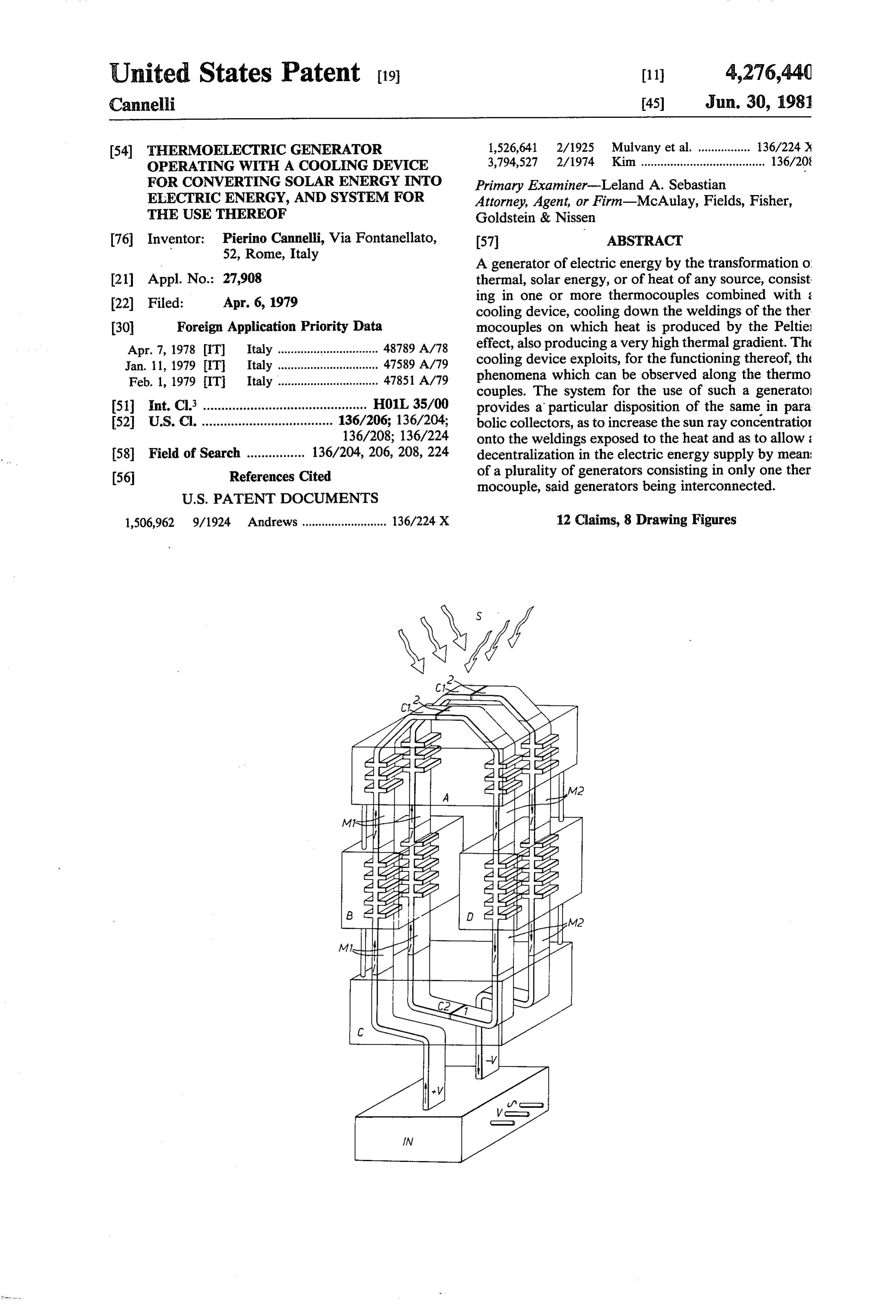
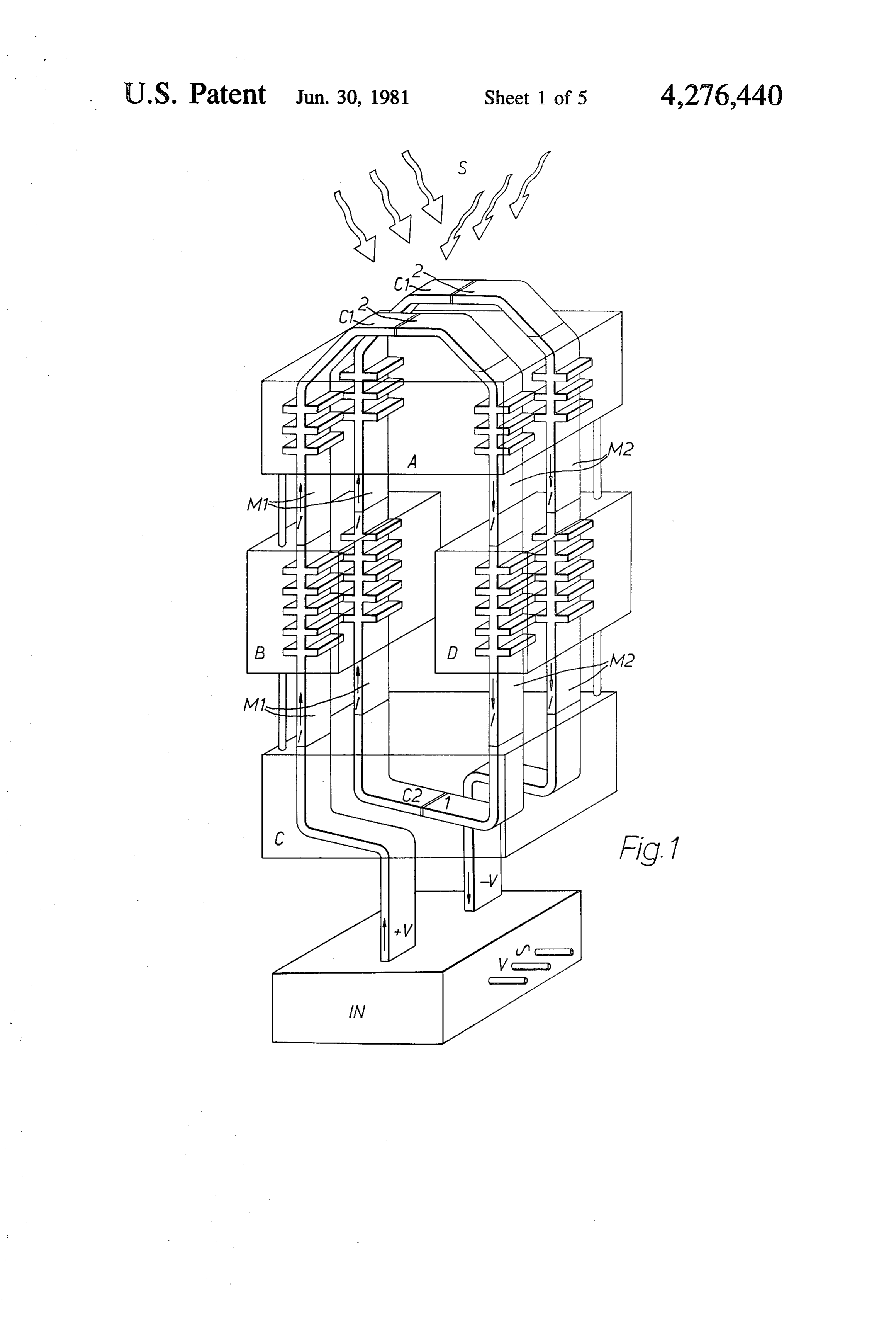
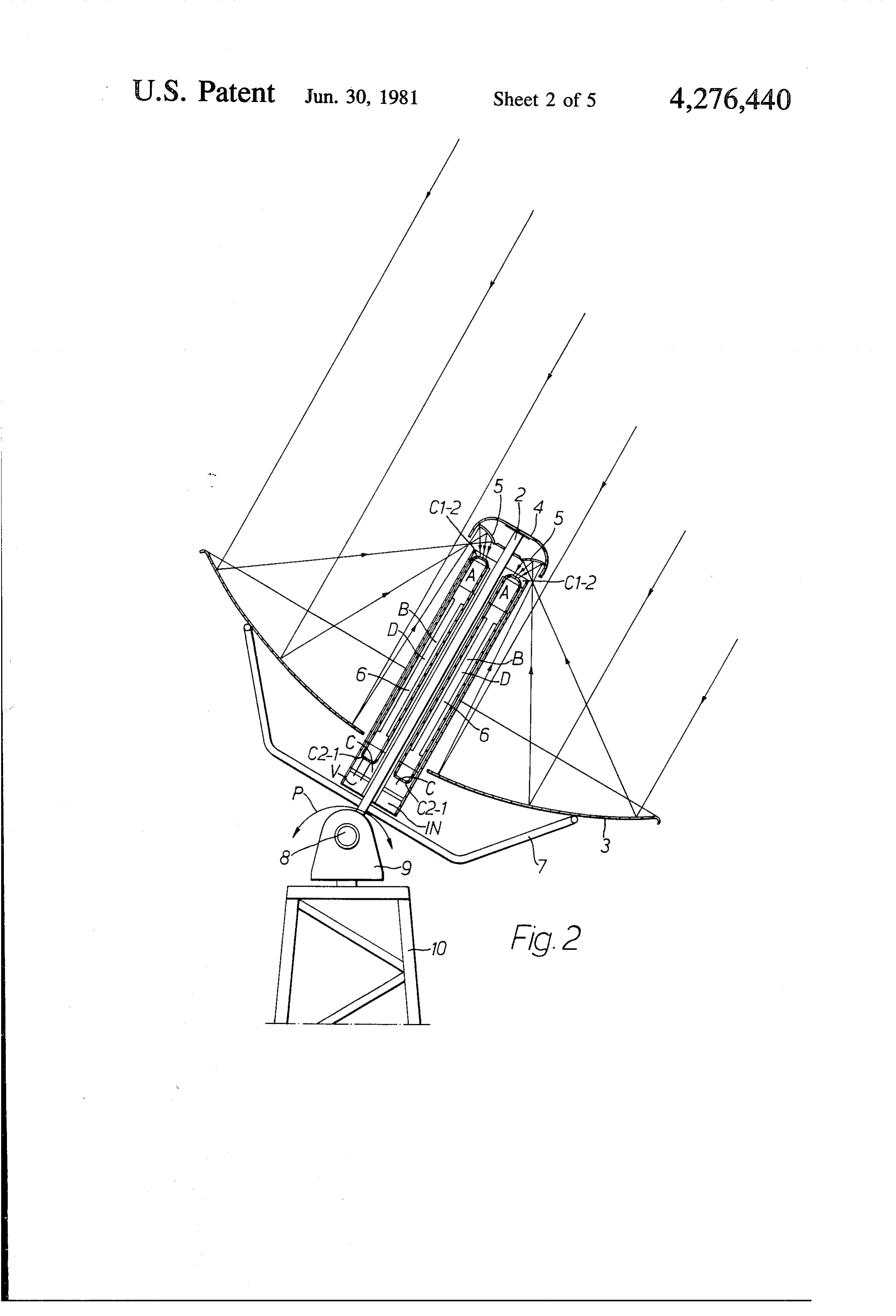
energy into electric energy, can in fact be realized in a a.c., which will be then put on the distribution network, much easier way and with much lower realization and by means of an already known connection. conduction costs, the same being of 50% lower than the FIG. 2 shows a possibility of installation of the gener ones provided by the systems until now experimented. ator according to the present invention. Said generator furthermore allows the decentralization 5 In this embodiment, a plurality of generators 6 ac of the electric energy supply, as it can be used also in cording to the present invention are placed in dial ac reduced dimensions and therefore for a limited number cording to the generating lines of a cylindrical envelope of users, and thus still not increasing the cost or reduc i placed along central axis 2 of a paraboloid 3, with a ing the efficiency. - specular surface, already known. Envelope 1 projects of The present invention will be, hereinbelow, described 10 a certain section beyond the base of paraboloid 3, so more in detail referring to those embodiments described that weldings C2-1 exposed to cooling down are found with an exemplifying and not limitative purpose, being in a shadow area, while weidings C-2 exposed to heat understood that other forms, proportions and dispositi are found in the focus area of the paraboloid. At the end ons may be adopted, without therefore going out of the of central axis 2 of the paraboloid, which is found in the limits of the present invention. In the following descrip- 15 focus area, a cap 4 is applied supporting a parabolic cap tion referring to the enclosed drawings, the figures 5 with a specular surface, placed with the concave part show: thereof turned towards the concave part of paraboloid FIG. 1, an axonometric view of a thermoelectric 3. Said cap 5 has the purpose of further increasing the generator working with a cooling device according to sun ray concentration, which from said cap are re the present invention, said cooling device being applied 20 flected on Zones C1-2 of the thermocouples of genera to the thermocouples and connected to a current con tors 6 and, consequently, of increasing the heat on said vertor; ZOS.
FIG. 2, a section of an embodiment provided with a Generators 6 are interconnected in parallel and/or in plurality of generators, placed in dial in a rotation pa series, and the ends of the connection, shown in FIG. 2 raboloid collector; 25 with --V and -V, are also contained in envelope 1, as FIG.3, a top view of the dial disposition of a plurality well as in convertor IN. Paraboloid 3 is supported by a of generators according to the present invention ac support frame 7 applied to central axis 2, which has the cording to FIG. 1; fulcrum thereof at 8 onto a flask 9 so that it can be FIG. 4, a transversal section according to line A-A adjusted in height according to arrow P. Flask 9 is in of FIG. 3; 30 turn pivotally placed onto a base 10. FIG. 5, the thermocouple of the generators, the metal Above disposition is shown more in detail in FIGS. 3 sheets welded one onto the other before being wound and 4.
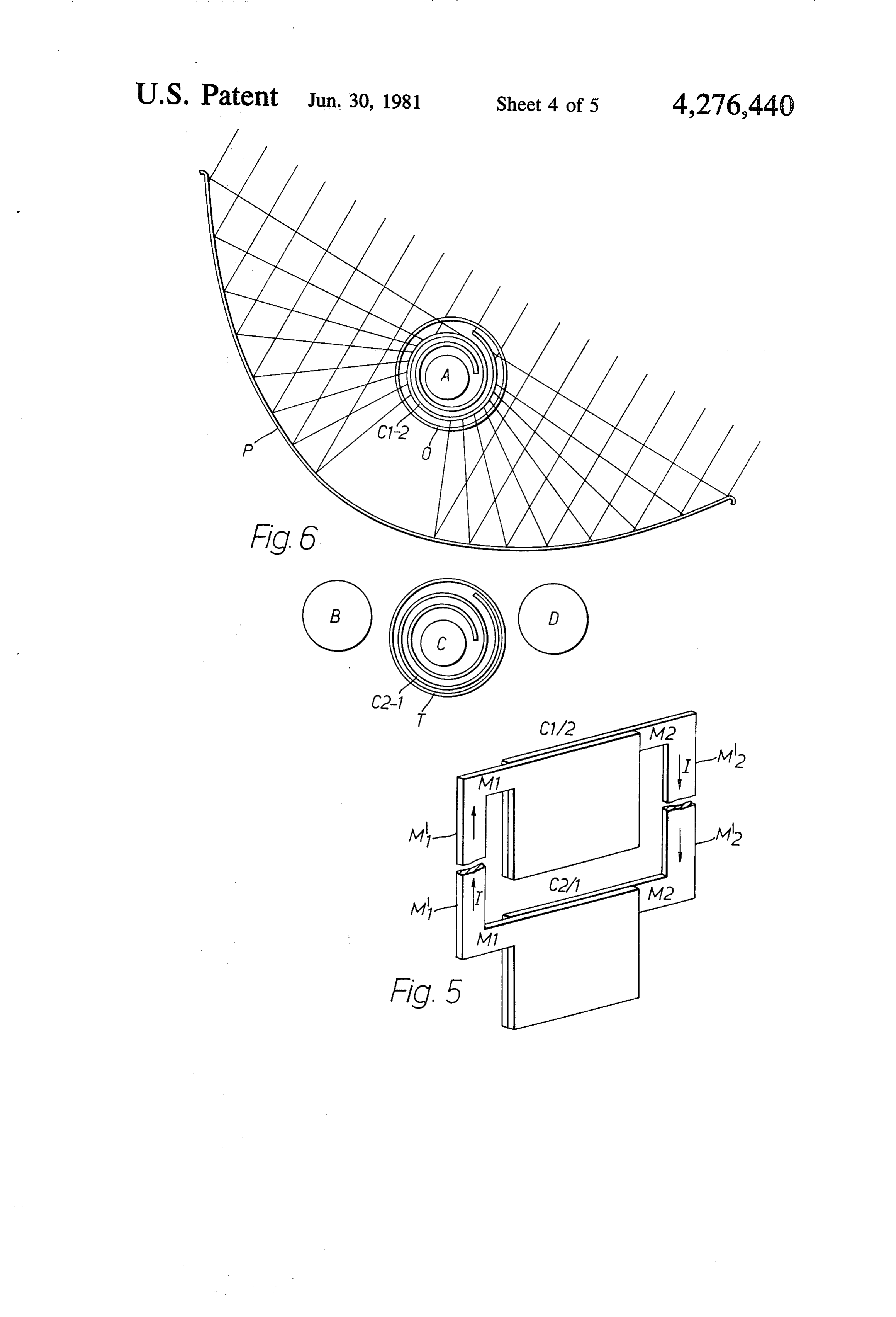
around the boiler and the refrigerator of the cooling FIG. 6 shows a different embodiment of the genera device; tor according to the present invention. In this embodi FIG. 6, a schematic section view, in enlarged scale, of 35 ment, each generator consists in a single thermocouple the disposition of the thermoelectric couple of FIG. 5 and therefore forms a modular unity to be connected to and to the cooling device of FIG. 7; others of the same kind as to form a system of any di FIG. 7, a schematic, axonometric view of the cooling mension. It has already been explained that this embodi device applied to the variant in the form of modular ment is cheaper than the first, due to the simplicity of unity; 40 the realization.
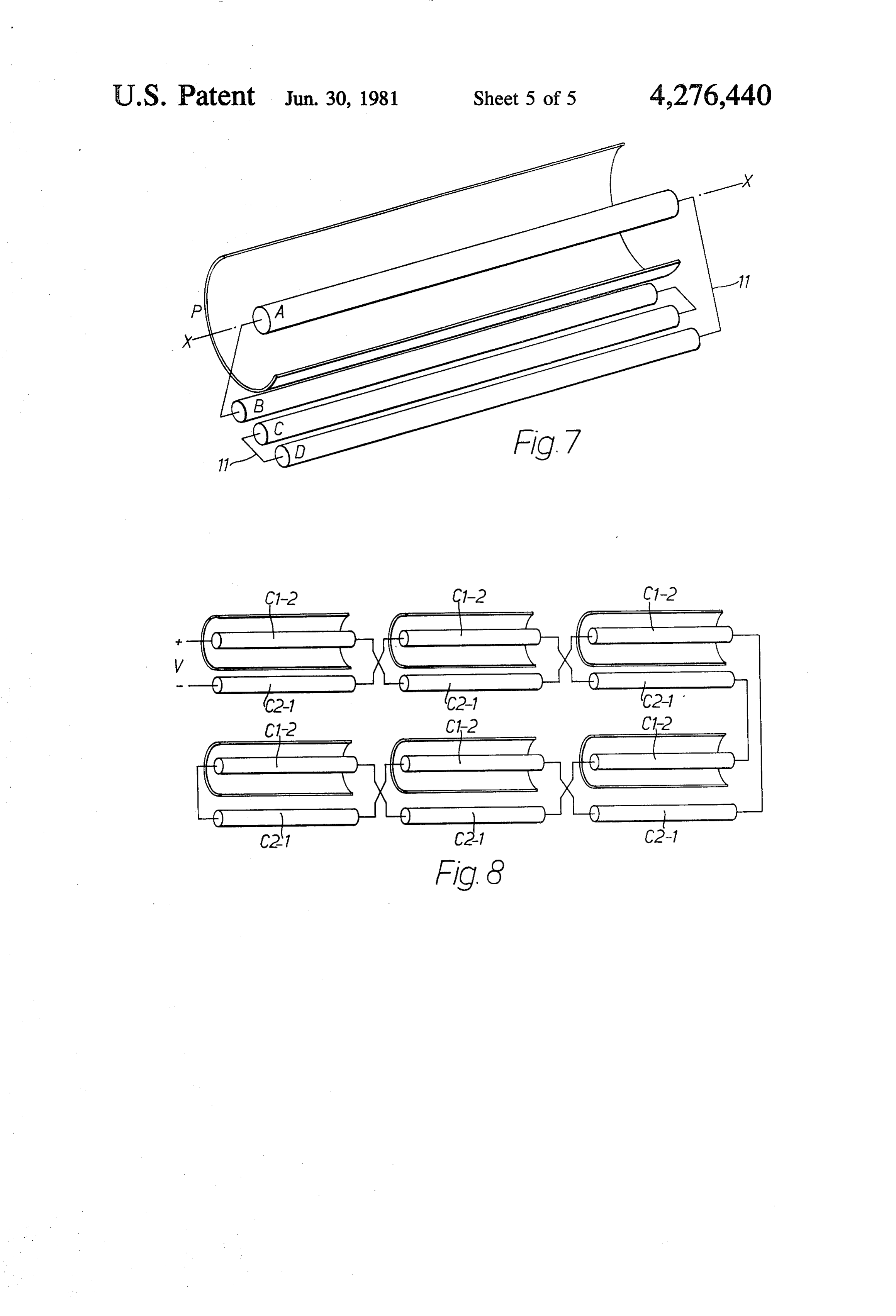
FIG. 8, a schematic view of the connection of more FIG. 5 clearly shows the two metal sheet couples M1, modular unities, as for FIGS. 5 and 6. M2 of different material, welded one onto the other as In FIG. 1, M1 and M2 show the different metal ele to form the hot welding zone C1-2 and the cold welding ments of the thermocouples (of which in the figure only zone C2-1, before being wound respectively around two are shown), placed close, like a spiral, the ends +V 45 boiler A and refrigerator C.
and -V being inserted in current convertor IN. Weld M'1 and M'2 respectively show connection arms of ings C1-2 can be noted exposed to the heat, opposite if the metal sheet couples. shows the current direction. weldings C2-1, exposed to the cooling action of refrig FIG. 6 shows, in section, how one of the metal sheet erator C. A, B, C and D show the elements of the cool couples is wound like a spiral around boiler A of the ing device. 50 cooling device and how both are placed in a tube Q out Boiler A contains cooling fluid which, under the of quartz or pirex, under vacuum, as to avoid a heat action of the heat supplied by the thermocouple, warms dispersion. The tube is placed along the focus area of a up, evaporates and is led, in the gaseous status, to con parabolic cylindrical collector P which, in an already densor B. In condensor B, from which heat is sub well known way, can be adjusted with respect to the stracted by the Thompson effect which is produced 55 sun. FIG. 6 still shows how the other couple of metal along elements Mi of the thermocouples, the gas cools sheets is wound around refrigerator C of the cooling down and goes over to refrigerator C where, due to the device and how both are placed within a tube T out of sudden expansion thereof, it produces cold onto weld insulating material. In FIG. 6 the positions of condensor ings C2-1. From refrigerator C the gas goes back again B and of absorber C of the cooling device are also sche towards boiler A, passing through absorber D, where it 60 matically sketched in, the condensor and the absorber absorbs the heat which now is given in by the Thornp being connected, by means of a tubing, here not shown, son effect produced along elements M2 of the thermo to boiler A and refrigerator C.
couples. FIG. 7 is an axonometric, schematic view of the posi Thus a remarkable thermal gradient is established tion of boiler A in the focus area of parabolic cylindrical between weldings C1-2 heated up and weldings C2- 65 collector P, as well as the position of elements B, C, D cooled down and thus a considerable e.m.f. will be of the cooling device, interconnected, of tubing 15. obtained at the ends --V and - V of the thermocouples. Finally, FIG. 8 schematically shows a connection in Convertor IN provides the transformation of d.c. into series of a plurality of modular unities, i.e. of a plurality
Page 10
of generators realized according to a variant of the beyond the convex area of paraboloid (3), and wherein present invention. From that figure it can be seen how paraboloid (3) can be inclined with respect to the sun, the connections of the metallic sheet couples relative to and rotated onto itself.
hot welding zone C1-2 and to cold welding zone C2-1 7. A system according to claim 6, wherein above of a modular unity are crossed with the corresponding welding zones (C1-2) to be exposed to the heat a para couples of the successive modular unity as to obtain a bolic cap (5), the concave part thereof being turned reciprocal balance of the Thompson effects which can towards the concave part of paraboloid (3), is provided, be observed as giving in and respectively absorbing heat as to obtain a further sun ray concentration onto weld along connection arms M' and M'2 of different materi ings (C1-2) and, consequently, a major efficiency of the als, 10 system. . ...
I claim: 8. A system according to claim 7, wherein on hot 1. A generator of electric energy for the conversion weldings (C1-2) a honeycomb structure is provided from solar, thermal energy, or from any other appropri consisting in small glass cylinders with the purpose of ate heat source, consisting in one or more thermocou avoiding any heat dispersion by re-irradiation and by ples combined with an absorption cooling device acting 15 convection.
on one of the weldings of the thermocouple(s), wherein 9. A system for the use of a generator of electric the thermocouple(s) are out of materials (M1, M2) pro energy according to claim 1, wherein the generator vided with the most appropriate electric anc mechanic consists in only one thermocouple and the welding Zone features, and wherein the absorption cooling device (A, (C1-2) to be heated up consists in two thin sheets (M1, B, C, D) is fed by the same heat supplied along the 20 M2) out of different materials welded the one onto the thermocouple(s) used, and said cooling system acting other, on that welding of the thermocouple(s) on which, by coolingand wound like a spiral around boiler (A) of the device, said boiler having the form of a cylinder the Peltier effect, heat is developed, with the purpose of and being appropriately placed along the focus area of reducing of a maximum the temperature and therefore a rotation paraboloid collector to maintain at a high level the thermal gradient between (C2-1) to be cooled down, also(P),
consisting in two thin hot weldings (C1-2) and cold weldings (C2-1) of the sheets of the same materials of the first welding zone, thermocouple(s), thus obtaining a high e.m.f. value and welded the one onto the other, is wound like a spiral consequently, a high power value.
2. A generator of electric energy according to claim aroundofrefrigerator (C) of the cooling device, also in the 1, wherein the Thompson effect is exploited for the 30 form a cylinder, being placed opposite to the convex feeding of condensor (B) and an absorber (D) of the part of said cylindric-parabolic collector (P), i.e. in the cooling device when said Thompson effect can be noted absorberarea shadow of the sun rays, a condensor (B) and an
(D) of the cooling device being placed in the as an absorption, respectively as a giving in of heat along the arms out of different metals of the thermocou same shadow area, parallel between boiler (A) and re ples. 35 frigerator (C), being interconnected and connected 3. A generator of electric energy according to claim thereto by a feeding tubing in the cycle of the cooling 1, wherein the thermocouples are connected by welding fluid.
in an alternate succession of the component metals (M1, 10. A system according to claim 9, wherein the two M2) as to assume a disposition like a spiral, so that all different metal sheets forming hot weldings (C1-2) are the weldings (C1-2) to be exposed to the heat are always appropriately blackened to favour the heat absorption aligned and opposite to weldings (C2-1) to be cooled of the same, and wherein the same, together with boiler down. (A), are placed under vacuum in a tube (Q) out of quartz 4. A generator of electric energy according to claim or pirex, to avoid heat dispersion, and wherein the two 1, wherein end (--V) of the first element of the first sheets out of different metals forming the cold weldings, thermocouple and end (-V) of the last element of the 45 wound around refrigerator (C), are in turn placed, to last thermocouple are connected to a conventor (IN) gether with the refrigerator, in a tube (T) out of a mate which transforms the direct current produced by the rial insulating towards the outside.
generator into alternate current to be put on the distri 11. A system according to claim 9 or 10, wherein the bution network. connection of the metal sheet couples corresponding to 5. A generator of electric energy according to claim 50 hot welding zone (C1-2) of one modular unity takes 1, wherein the hot welding zones are placed in appro place crossed with the corresponding couple of the priate, single containers out of insulating and refractory successive modular unity as to obtain a reciprocal ther material, resistant to the smelting temperature of the mal balance of the Thompson effects, which can be alloy of the weldings. observed in the form of giving in, respectively of ab 6. A system for the use of a generator of electric 55 sorption of heat along connection arms (M1, M2) out of energy according to claim 1, wherein a plurality of different materials.
generators (6) are placed in dial according to the longi 12. A system according to claim 1, including tudinal central axis (2) of a rotation paraboloid collector a honey-comb structure comprising small glass cylin (3) provided with a specular surface, so that welding ders provided on said hot weldings for avoiding zones (C1-2) to be exposed to the heat are found in the any heat dispersion by re-irradiation and by con focus area of the paraboloid, while welding zones vection.
(C2-1) to be cooled down are found in a shadow area,
Provenance
- Collection
- Cited prior art
- Original PDF
- patentimages.storage.googleapis.com →
- Filed
- 1979-04-06
- Pages
- 10
- Method
- pdftotext (the PDF's own text layer) + pdftoppm 300dpi page scans
- Source
- Google Patents bibliographic record
- Granted
- 1981-06-30
- Inventors
- Pierino Cannelli
- Transcribed from
- patentimages.storage.googleapis.com →