patent · US4263961
Method and an apparatus for storing heat energy
28 April 1981
Page 1 — bibliographic record
United States Patent (19) 11) 4,263,961 Morawetz et al. 45 Apr. 28, 1981 54 METHOD AND AN APPARATUS FOR different densities and being non-mixable. When heat is STORING HEAT ENERGY discharged from the heat storage apparatus, the first (75) Inventors: Ernst Morawetz; Birgit I. Morawetz, material, which has the lower melting temperature, is both of Staffanstorp, Sweden brought into direct heat exchanging contact with the second material which is essentially in a liquid state by 73) Assignee: Teknoterm Systems, AB, Maimo, causing droplets of the first material having a lower Sweden temperature than the melting temperature of the second (21) Appl. No.: 960,535 material to pass through the second material, whereby 22 Filed: Nov. 14, 1978 the droplets of the first material are heated and may be used in order to give off the heat in an outer circuit, 30 Foreign Application Priority Data while the second material sets essentially in droplet Nov. 14, 1977 SE Sweden ................................ 7712829 form. When heat is supplied to the heat storage appara tus, liquid flow channels are formed through the second 51) Int. Cl. .............................................. F28D 21/00 material, which is essentially in a solid state, whereupon 52 U.S.C. .................................... 165/1; 165/104 S; droplets of the first material, which have a higher tem 126/436 perature than the melting temperature of the second 58) Field of Search ................ 165/104 S, 1; 126/436, material are caused to pass through the flow channels 126/400; 62/430 whereby the second material around the flow channels 56) References Cited are caused to melt by direct heat exchange. Preferably,
3,848,416 1/1974 Bundy .......................... 165/104 S X material, the first material being sprayed or showered 4,086,958 5/1978 Lindner et al. ................... 165/104 S onto the material. The hybride heat storage apparatus comprises a vessel containing the first and the second
Primary Examiner-Albert W. Davis material, the said materials being located in layers on Attorney, Agent, or Firm-Jones, Tullar & Cooper top of each other; supply line which comprises a droplet 57 ABSTRACT forming apparatus, whereby the first material, which has the lower melting temperature, is divided into drop
A method and an apparatus for storing heat energy in a lets; and a discharge line for the first material. hybride heat storage apparatus comprising a first and a second material are disclosed, the first and the second materials having different melting temperatures and 9 Claims, 4 Drawing Figures
Page 2
Drawing sheet — no readable text.
Page 3
Drawing sheet — no readable text.
Page 4
Salt hydrates have a limited life (d). However, non
METHOD AND AN APPARATUS FOR STORING complex materials such as water/ice or paraffins are HEAT ENERGY free from this problem.
Furthermore, salt hydrates in particular have a high
The present invention relates to a method and an 5 corrosiveness (d), which creates problems at the encas apparatus for storing heat energy in a hybride storage ling.
apparatus, the heat storage capacity of which is at least Many materials having a high melting heat have a too twice as great as the heat storage capacity of a water high or a too low melting temperature to be technically tank having the same outer volume. usable (f). In order to avoid this problem it is possible to A hybride heat storage apparatus comprises two dif 10 use a heat pump.
ferent materials having different melting temperatures According to the present invention the above prob and different densities, the materials having a very lim lems are solved in the following way. A non-complex material, such as paraffin, water or an oil, is used as a ited relative solubility, i.e. they are not mixable. One of heat the materials having the lower melting temperature is storing medium, whereby the problems connected used as a heat conveyor, while the other material is used 15 with the phase conversion (a) the life of the system (d) as a heat storage material by using its melting heat. If the corrosiveness (d) and the melting temperature (f) the other material has a bad heat conducting capacity are avoided. As an example a paraffin is discussed here there are still problems concerning the heat transfer inafter without limiting the invention to this particular material. Paraffin has the drawback of having a heat between the two materials, which problems will be 20 conducting appreciable at small temperature differences. capacity which is markedly inferior to that The heat transfer between a solid (or liquid) material of water for instance, especially in a molten state, for of low heat conducting capacity and a liquid heat car which reason the problem connected with the heat rier is technically a very difficult problem and normally transfer must be solved.
requires large temperature gradients and large heat 25 icalThe present invention is based on the following phys properties.
exchanging surfaces which are expensive. In a solar Two non-mixable materials can be brought into im heating system these problems become additionally difficult since the heat from the sun collector will nor mediate contact with each other without being mixed, i.e. becoming dissolved in each other. Furthermore, the mally be available at a relatively low temperature level. surface
The efficiency of a solar heating system is consequently 30 divided of a liquid material may be multiplied by being dependent on whether an effective heat transfer can liquids of into drops or droplets, Finally, two non-misable take place at low temperature differencies, in particular other without different densities will form layers on each at the heat storage apparatus. mixing.
These physical
The present invention relates specifically to adapting the first material which properties are used in such a way that is the heat carrier and thas the a hybride heat storage apparatus for use together with a 35 lower melting temperature, e.g. water, is divided into solar heating system. drops or droplets and is caused to pass through the Experiments have been made for a long time in order other material. e.g. paraffin in drop form, in which to solve the problems connected with the storing of heat connection the heat carrier will effectively assume the in a salt hydrate melt, e.g. glauber salt, calcium chloride temperature of the other material due to the large hydrate, iron chloride hydrate, etc. These materials contact surface.
have a relatively high melting heat and are relatively An object of the present invention is to provide a inexpensive. The process for storing melting heat is method of storing heat energy in the form of melting seemingly very simple. Heat absorption and and storing heat in a hybride heat storage apparatus consisting of a take place by melting chrystalline material in a solid first and a second material having different melting state by supply of heat, whereby the material is obtained 45 temperatures and different densities, which materials in a liquid state. When heat is given off the reverse are not mixable in their liquid states. The method com process takes place. prises the steps that when heat is extracted from the heat The problems derives chiefly from storage apparatus, the first material, which has the (a) the phase conversion process lower melting temperature, is brought into direct heat (b) the heat transfer between the meltable material 50 exchanging contact with the second material which is and a heat carrier, usually a liquid or a gas essentially in a liquid state by causing droplets of the (c) life of the system first material having a lower temperature than the melt (d) the corrosiveness of the meltable material ing temperature of the second material to pass through (e) the embodiment of the encasing and the heat ex the second material, whereby the droplets of the first change 55 material are heated and may be used in order to give off (f) the melting temperature the heat in an outer circuit, while the second material During the phase conversion process (a) unfavoura sets essentially in droplet form and that when heat is ble effects may occur, such as phase separation, sedi supplied to the heat storage apparatus, liquid flow chan mentation of chrystals, chemical disintegration and nels are formed through the second material, which is undercooling. essentially in a solid state, whereupon droplets of the The heat transfer (b) and the encasing and heat trans first material, which have a higher temperature than the fer (e) are generally brought about in such a way that melting temperature of the second material are caused the heat storing material is enclosed in a large number of to pass, through the flow channels, whereby the second small containers each of which is in contact with the material around the flow channels is caused to melt by heat carrier. As a result, good heat transfer is obtained 65 direct heat exchange. Preferably, the first material has a but the encasing will easily become expensive and the higher density than the second material, the first mate containers must be piled or locked in any suitable man rial being sprayed or showered onto the second mate e. rial.
Page 5
Another object of the invention is to provide a hy charged with new heat energy until all the paraffin has bride heat storage apparatus comprising a vessel con molten once again.
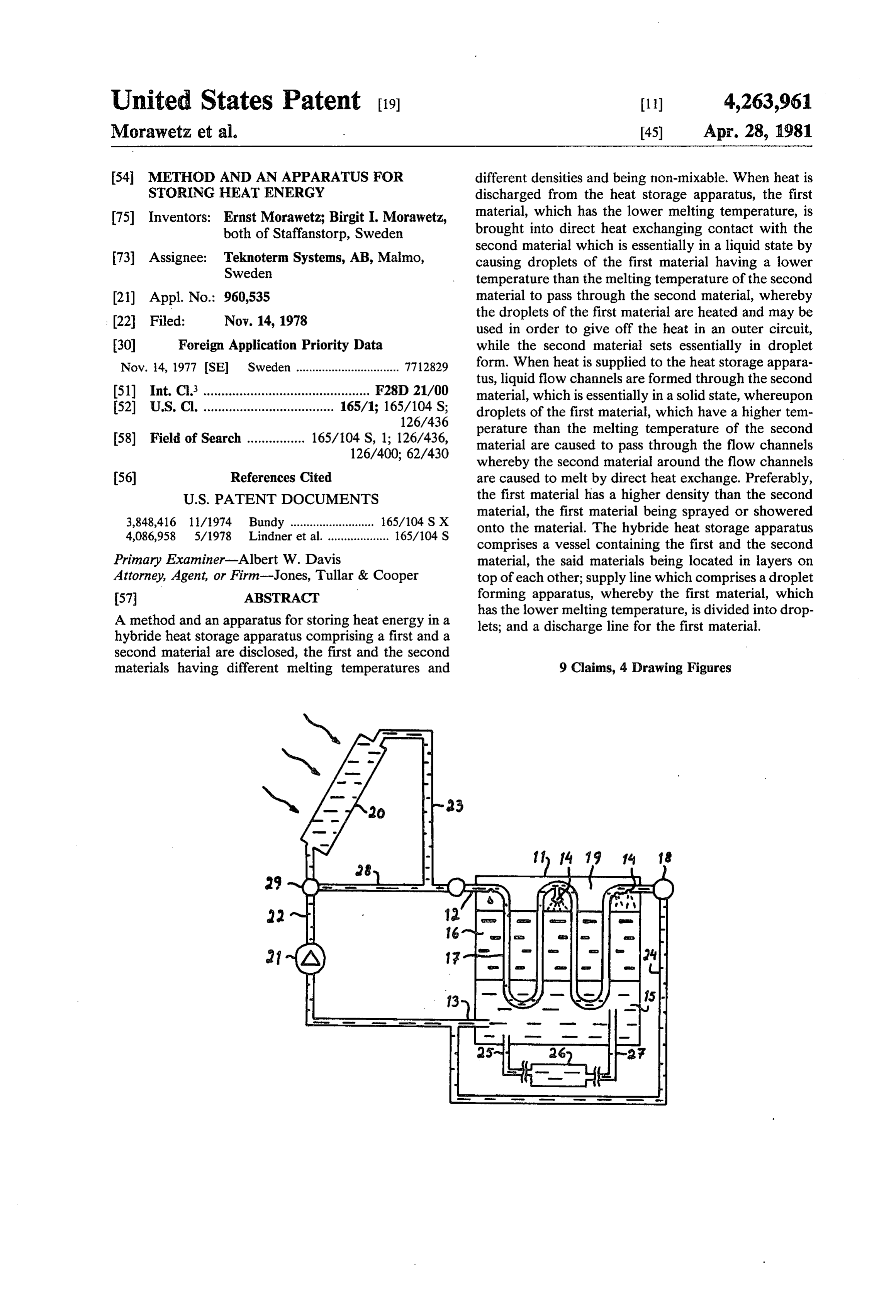
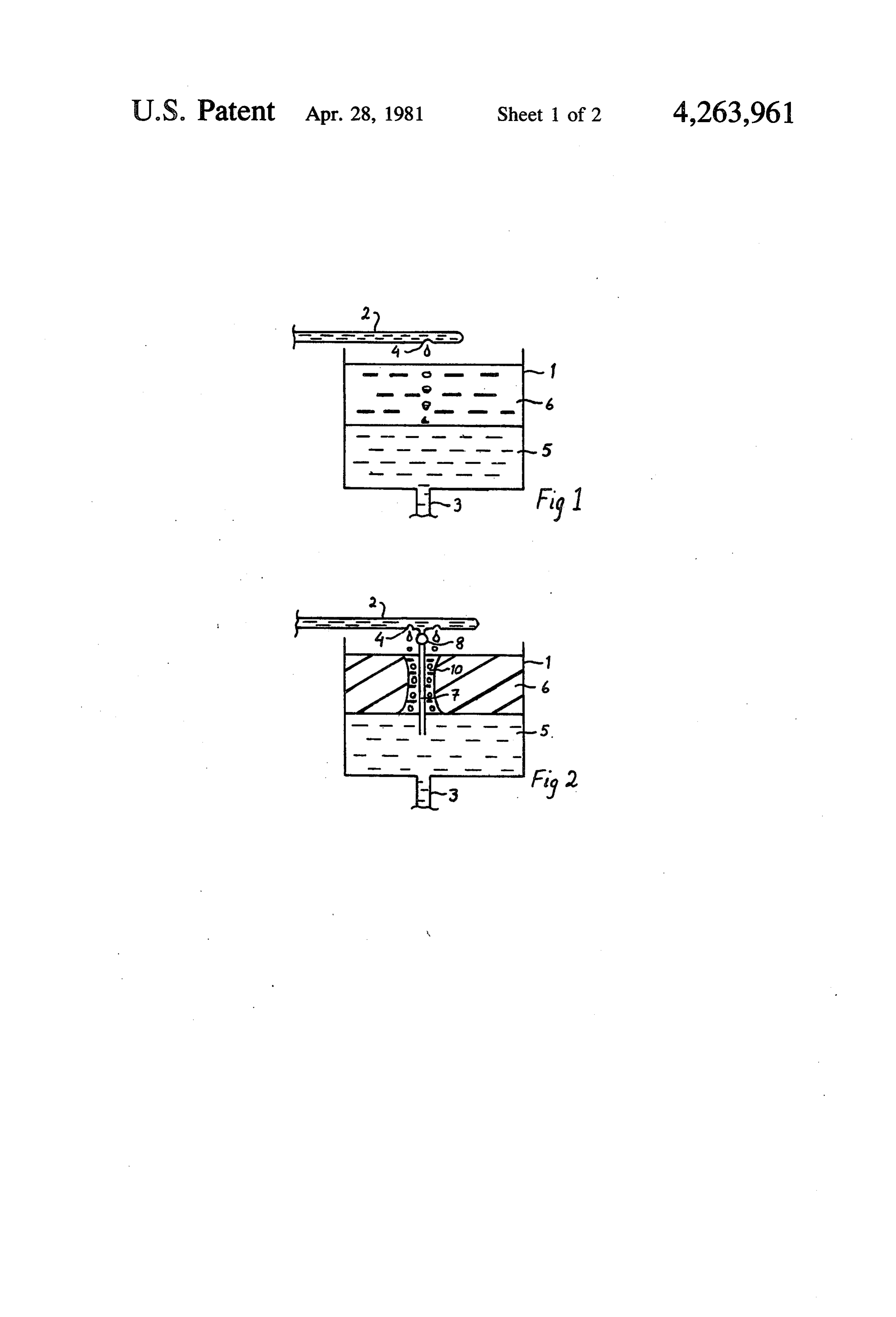
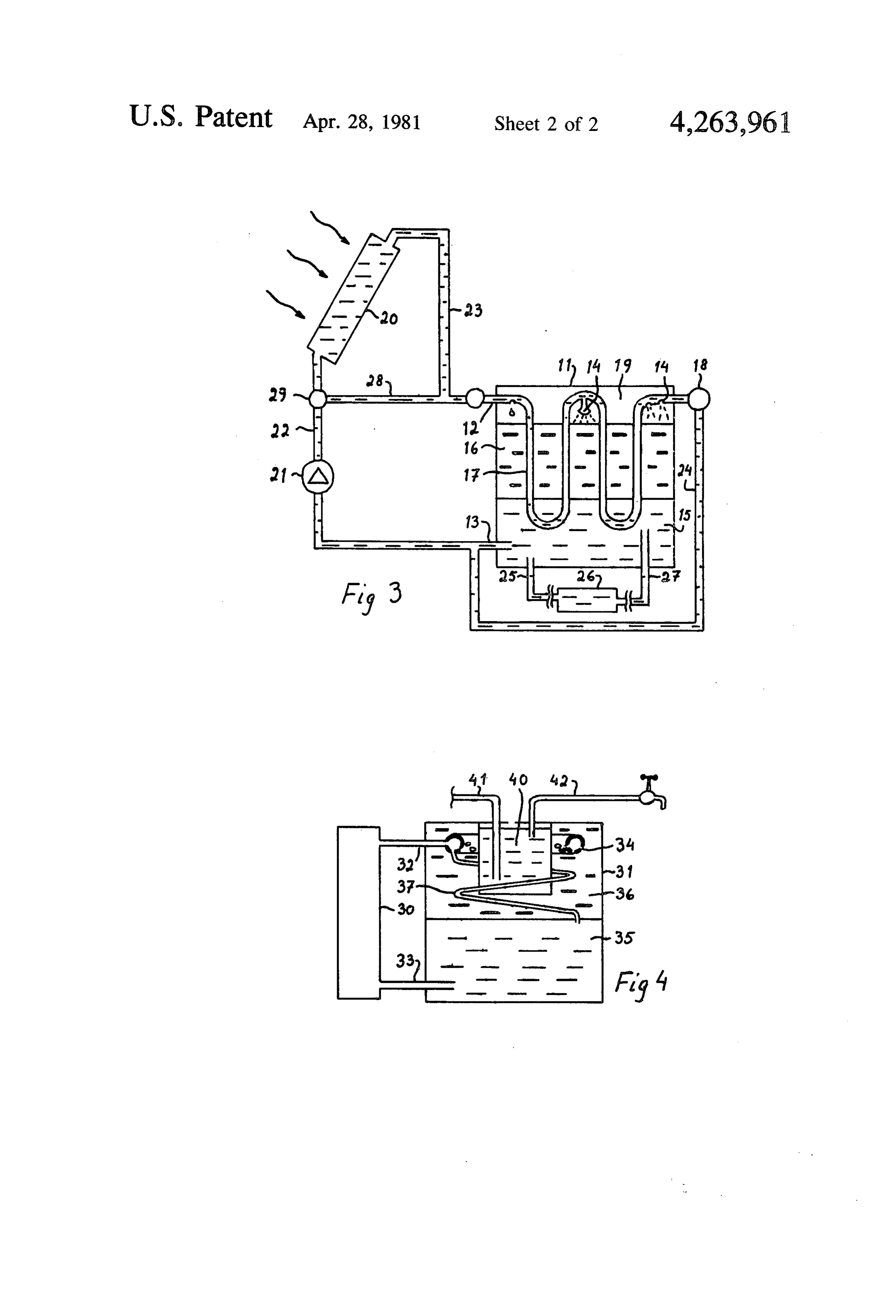
taining the first and the second material, the said materi FIG. 2 shows how the heat storage apparatus is als being located in layers on top of each other; and a charged with heat. The heat storage apparatus accord supply line which comprises a droplet forming appara ing to FIG. 1 has been supplemented in this case with a tus, whereby the first material, which has the lower vertical pipe 7 and a valve 8. The pipe 7 extends from melting temperature, is divided into droplets; and a the inlet 2 through the layer of paraffin 6 and opens into discharge line for the first material. the water 5 beneath the paraffin layer. If hot water The invention will now be described in more detail having a temperature of more than 52 C. is supplied with the aid of a preferred embodiment, reference being O through the inlet 2, the said water is allowed by means made to the accompanying drawings. of the valve to pass through the pipe 7 to the water FIG. 1 and FIG. 2 are diagrammatic views showing layer 5 lying below. AS aresult hereof that portion of the principle of the invention. the paraffin which lies around the pipe 7 will melt, FIG. 3 is a diagrammatic view showing an applica whereby a flow channel 10 is formed through the solid tion of the invention in a solar heating system, and 15 paraffin layer 6. At this stage the valve 8 is closed and FIG. 4 is a diagrammatic view showing an applica the hot water is allowed to drip through the drop form tion of the invention using a heat pump and in order to ing device 4. The dripping water may pass through the prepare hot tap water. flow channel 10, whereby a direct heat exchange be FIG. 1 shows the principle for discharging heat from 20 tween the water droplets and the molten paraffin in the the heat storage apparatus. The apparatus consists of a flow channel takes place, and the heat is transferred vessel 1 having an inlet 2 and an outlet 3. The vessel 1 from theis water droplet to the paraffin and the flow contains a quantity of the first material 5 located at the channel expanded. Finally, the entire paraffin layer 6 has molten, the heat storage apparatus being fully bottom of the vessel and a quantity of the second mate charged.
rial 6 floating on the first material. The first material The water 5 in the vessel 1 may be used in an outer consists of water and the second material consists of paraffin. The paraffin has melting temperature of ap heat circuit in order to give off and/or absorb heat. proximately 52° C. and is in a molten state. The inlet may As mentioned above, other combinations of materials pipe 2 is provided with a drop forming apparatus 4, be used, such as water/oil. If the oil has a higher density than the water the water may constitute the whereby water is given off drop-wise. The paraffin 6 30 melting and the water 5 at the bottom of the vessel 1 have the heat storing material at O C. It is also possible same temperature, which is higher than 52 C., e.g. 54 to use an oil having a lower density than water, such as C. Since the paraffin is lighter than water its floates on aprovided slightly vicous thermo oil. In that case the inlet 2 is at the bottom of the vessel 1 and the outlet 3 the water.
is provided
If cold water having a temperature of less than 52 C. 35 thermo oil lyingat the upper, portion of the vessel, the is supplied through the inlet 2 and is allowed to drip heat carrier, whereby on top of the water/ice constituting the through the drop forming apparatus 4 the following an inverted system is obtained. The drop forming device process takes place. The droplet reaches the surface of nozzle similar to a shower nozzle 4 preferably consists of an having a multitude of the molten paraffin and begins to sink through the paraf small apertures. The water passing through the orifice is fin layer. While sinking the droplet absorbs heat from 40 divided into fine droplets or into a drizzling flow. By the hot paraffin, while the paraffin in the immediate the expression droplets in the present specification are vicinity of the droplet is cooled. When the temperature meant not only separate droplets but also a flow of more of the paraffin in the immediate vicinity of the droplet or falls below 52 C. a certain amount of the paraffin be ingless continuous droplets or drops, or a flow consist gins to set on the underside of the droplet. The set paraf. 45 possibly inmultitude
part of thin yets or squirts, which may consist of drops or droplets. An essen fin forms a slightly cup-shaped droplet which accompa tial feature of the invention nies the water droplet downwardly through the paraf divided and is disintegratedis that in the water supplied is such a way that its fin, since paraffin in a solid state has a higher density contact surface with the paraffin becomes great. The than molten paraffin. When the combination of the heat vertical pipe or choking heat pipe 7 performs two func droplet and the paraffin droplet reaches the boundary 50 tions, a heat exchanging function and a choking func between the water and the paraffin the paraffin droplet tion. The exchange takes place between the outer sur stops at the boundary while the heated water droplet face of the pipe and the adjacent paraffin so that flow passes the boundary. Accordingly as more cold water is channels 10 are formed during the initial stage of the applied through the inlet 2 additional paraffin droplets charging operation. The choking function may be per are formed the boundary between the paraffin and the 55 formed by means of a choke valve, a check valve or an water. Finally, most of the liquid paraffin has become on-off-valve. Alternatively, the choking heat pipe 7 transformed into a solid state, which implies that the may consist of a capillary tube, as is explained in more melting heat stored in the paraffin has been withdrawn approximately at the melting temperature of the paraf 7detail in connection with FIG. 4. The choking heat pipe may be essentially vertical or extend downwardly in fin, i.e. at 52 C., by direct heat exchange between the 60. an axial spiral or may be arranged in an another manner water droplets and the surrounding paraffin. When in such a way as to have a downwardly inclination, so almost all paraffin has set additional water droplets that the water may flow downward in the pipe. cannot pass and the process comes to a stop. As a result FIG. 3 shows how the heat storage apparatus may be of the fact that the set paraffin droplets are slightly built into a heating system for heating of houses com cup-shaped a small quantity of water is enclosed in the 65 prising a solar collector. The heating system comprises set paraffin mass. This limited water quantity contrib a vessel 11 which is filled with water 15 and paraffin 16. utes to improving the heat conductivity in the solid The space 19 is filled with a gas. The system further paraffin. The heat storage apparatus may now be more comprises a solar collector 20, an inlet pipe 12, an
Page 6
outlet pipe 13, a drop forming device in the nature of supplied via a supply line 41 and hot water is discharged perforated pipe portions 14 or a nozzle 14a and vertical via a discharge pipe 42. When hot water is discharged pipe portions 17. A circulation pump 21 pumps the the paraffin around the hot water tank 40 will set, at the water in a circuit from the outlet pipe 13 via the riser same time as the supplied cold water is heated. The pipe 22 to the solar collector 20 and furtheron through drop forming apparatus 34 is located around the hot a down pipe 23 and a check valve to the inlet 12 of the water tank 40. From the drop forming apparatus there tank 11. A shunt pipe 24 is connected from the end of extends a capillary tube 37 in a spiral downwardly the inlet pipe 12 to the outlet pipe 13 and is controlled through the paraffin layer 36 and opens into the water by a valve 18. The valve may be a choke, check or layer 35 lying below.
on-off-valve. The shunt pipe 24 and the valve 18 may be 10 Let us assume that a paraffin layer 36 is in a com replaced by a capillary tube. A second outlet pipe 25 pletely solid state. In that case the holes or apertues in leads to the heat consumer 26, from where the water is the dropforming apparatus 34 are obstructed by set returned directly to the tank 11 via the supply pipe 27 or paraffin. If hot water is supplied through the inlet.32 to the outlet pipe 13. A second shunt pipe 28 connects this cannot flow out through the obstructed openings the riser pipe 22 with a down pipe 23 via a three-way 15 but will pass through the capillary tubes 37. In that case valve 29. flow channels are formed through the paraffin layer, The function of the system will now be explained. like before. The flow through the capillary tubes is so When heat is supplied the three-way valve 29 is in the insignificant that it can be disregarded. . position where the shunt pipe 28 is closed. At the begin The heat storage apparatus according to the inven ning the valve 18 is open. Water heated by the sun is 20 tion may also be connected with separate inlets for now driven by means of a pump 21 from the solar col charging and discharging. In that case the inlet pipe for lector 20 through the down pipe 23 through the inlet supplying heat may be completely enclosed in paraffin pipe 12 and the pipe portions 14 and 17 and further with the perforated apertures opening into the paraffin through the valve 18, the shunt pipe 24 to the outlet layer. However, the inlet pipe should be located in a pipe 13 and the pump 21. Essentially no water at all will 25 space above the paraffin layer, or else the perforated come out through the perforated pipe portion 14 since apertures will quickly be obstructed by set paraffin. the discharge resistance for the water through the per Capillary tubes may also be used in the embodiment forated apertures is greater than the flow resistance according to FIG. 3 instead of the shunt pipe 24 and a through the shunt pipe. The paraffin 16 around the pipe valve 18 or as a heat choking pipe which passes through portion 17 begins to melt, whereby flow channels are 30 the paraffin layer and opens into the water layer. At the formed. In that connection the valve 18 is closed which initial stage of the heat supplied to the apparatus the implies that water begins to be forced out through the flow resistance through the capillary pipes is less than perforated apertues and begins to pass through the par the discharge resistance through the perforared aper affin layer to the water layer below, whereby the heat tures. As soon as flow channels have been formed the energy of the water is given off to the solid paraffin 35 discharge resistance will become reduced and the water which will melt. The water flows through the outlet 13 will flow essentially along the way of less resistance to the pump 21 and through the riser pipe 22 to the solar through the perforated apertures and the paraffin layer collector 20. At the same time, a partial quantity of while the flow through the capillary pipe may be disre water may be circulated in the circuit 25, 26, 27 to a heat garded. The dimension of the capillary pipe is adjusted consumer. This consumer circuit is not disclosed in 40 in such a way that this function will be obtained. detail since it does not form part of the present inven The invention is not limited by the above embodi tion. ments but the invention should encompass all modifica When heat is withdrawn or discharged while the tions which fall within the scope of the invention as set solar collector is not producing heat energy, for in forth in the appended claims.
stance at night, the three way valve 29 is reset in such a 45 What is claimed is:
way that the shunt pipe 28 connects the riser pipe 22 1. Heat exchange method for exchanging heat be with the down pipe 23. The valve 18 is closed. Cool tween first and second materials which are not mixable water from the supply pipe 27 flows through the outlet in their liquid states, said first material having a higher 13 to the pump 21 and further through the shunt line 28 density and a lower melting temperature than the sec to the inlet 12 or the vessel 11. The water is allowed to 50 ond material, said method involving a heat extracting drip through the paraffin layer and is heated to a ten mode and a heat storing mode, said heat extracting perature of about 52 C. and is allowed to flow through mode comprising the steps of causing droplets of first the heat consumer 26. When all stored heat has been material at a lower temperature than the second mate withdrawn no water can pass through the compact rial to pass through the second material and into a layer paraffin layer, for which reason the pressure will rise in 55 of first material whereby said droplets are heated while the space 19, which may be used as a control signal in said second material solidifies, said heat storing mode order to stop the pump 21. Alternatively, the pump may comprising initially establishing flow channels through be controlled in dependence of the temperature in the solidified second material and then directing droplets of paraffin layer and may be shut off when the temperature first material at a higher temperature than the melting falls below about 50 (or any other suitable tempera 60 point of the second material from a gas-filled space tures). positioned above the second material into said flow FIG. 4 shows the heat storage apparatus in connec channels to thereby melt second material and expand tion with a heating pump 30 in order to heat hot tap said flow channels.
water in a hot water tank. The system comprises a ves 2. A method as recited in claim 1, in which the flow sel 31 having an inlet 32, an external conventional ex 65 channels are initially established without directing the pansion vessel (not shown) and an outlet 33 and a drop first material toward the second material. forming apparatus 34. Enclosed in the paraffin layer 36 3. A method as recited in claim 2, in which the first there is a hot water tank 40 to which cold water is material is water and the second material is paraffin.
Page 7
4. A method as recited in claim 3, in which the flow said first material, a layer of said second material above channels are initially established by passing first mate said layer of first material, and a gas-filled space above rial at a temperature above the melting point of the said layer of second material, a heat loop including second material through a loop including conduit means conduit means having apertures in said gas-filled space extending downwardly through the second material, which function both to direct droplets of first material and in which the enlargement of the channels is ob through said second material during said heat extracting tained by closing a valve in the loop whereby droplets mode and to direct droplets into the flow channels to of first material are caused to flow through apertures in enlarge said flow channels during the heat storage the loop positioned above the initially established flow mode.
channels. 10 8. Apparatus as recited in claim 7, in which said first 5. A method as recited in claim 1, in which the drop material is water and in which said second material is lets of the first material in the heat extracting mode are paraffin. v directed into the second material from a gas-filled space 9. Apparatus as recited in claim 8, in which said heat above the second material. loop and apertures are sized so that first material does 6. A method as recited in claim 1, in which the flow 15 not flow through said apertures when first material is channels are initially established by recirculating first circulating in said loop and in which said heat loop material at a temperature above the melting point of the includes valve means downstream of said apertures second material through a heating loop passing through which functions on closing to cause first material flow the second material. ing in said loop upstream of said apertures to flow 7. Apparatus for performing the method according to 20 through said apertures in thek formsk of droplets.
claim 1, comprising a vessel containing a lower layer of
Provenance
- Collection
- Cited prior art
- Original PDF
- patentimages.storage.googleapis.com →
- Filed
- 1978-11-14
- Pages
- 7
- Method
- pdftotext (the PDF's own text layer) + pdftoppm 300dpi page scans
- Source
- Google Patents bibliographic record
- Granted
- 1981-04-28
- Inventors
- Ernst Morawetz; Birgit I. Morawetz; Teknoterm Systems AB
- Transcribed from
- patentimages.storage.googleapis.com →