patent · US4262735
Installation for storing and recovering heat energy, particularly for a solar power station
21 April 1981
Page 1 — bibliographic record
United States Patent (19) 11) 4,262,735 Courrege et al. 45) Apr. 21, 1981 (54) INSTALLATION FOR STORING AND (56) References Cited RECOVERING HEAT ENERGY, U.S. PATENT DOCUMENTS
PARTICULARLY FOR A SOLAR POWER
STATION 2,933,885 4/1960 Benedeb et al. ............. 165/104 S X 3,107,052 10/1963 Garrison ....................... 165/104 S X 75) Inventors: Philippe Courrége; Jean Defiandre; 4, 14,600 9/1978 Newton ........................ 165/104 S X Francois Valette, all of Paris, France Primary Examiner-Albert W. Davis 73 Assignee: Agence Nationale de Valorisation de Attorney, Agent, or Firm-Daniel M. Rosen; J. David Dainow la Recherche, Neuilly-sur-Seine,
France 57 ABSTRACT (21) Appl. No.: 913,814 - An installation for storing and recovering heat energy having a principal application in solar power stations.
22) Filed: Jun. 8, 1978 The heat produced is stored in a storage reservoir when 30) Foreign Application Priority Data the converted energy demanded is less than the heat energy produced, and recovered in the opposite case,
Jun. 10, 1977 FR) France ................................ 77 17850 these operations being carried out entirely automati cally. The heat transfers are effected through a ther 51) int. Cl. .............................................. F28D 17/00 mofluid able to flow by streaming over containers of 52 U.S. C. .................................... 165/4; 165/104 S; any shape, enclosing a heat storage substance, and dis 60/659; 126/436 posed loosely or methodically in said storage reservoir.
60/659; 126/400, 436 25 Claims, 5 Drawing Figures
Page 2
Drawing sheet — no readable text.
Page 3
Drawing sheet — no readable text.
Page 4
Drawing sheet — no readable text.
Page 5
Drawing sheet — no readable text.
Page 6
(and so a larger quantity towards the storage reservoir),
INSTALLATION FOR STORING AND the lower the demand is for secondary energy com RECOVERING HEAT ENERGY, PARTICULARLY pared with the amount of primary energy collected in FOR A SOLAR POWER STATION the form of heat, and conversely, while assuming that the amount of primary energy collected in the form of
BACKGROUND AND SUMMARY OF THE heat is greater, at the moment considered, than the INVENTION energy demanded (heat storage); regarding furthermore The present invention relates to an installation for the flow of thermofluid supplying the second ex storing and recovering heat energy, particularly for a O changer, i.e. that in which the heat of the thermofluid is solar power station. transferred, e.g. to the water of a boiler, said distribut A solar power station must be designed so as to take ing means will take from the storage reservoir a quan into account the fluctuating and even intermittent na tity thereof the greater (and so a smaller quantity from ture of the heat source, since it concerns the sun. More the first exchanger), the higher the demand for second over, it is desirable for the installation which uses the ary energy with respect to the amount of energy pro heat energy, e.g. an installation converting heat energy 15 duced in heat form, and conversely, assuming that the into electric energy, to produce this secondary energy energy produced in the form of heat is less, at the mo even outside periods of sunshine, especially if it is a ment considered, than the energy demanded (heat des relatively isolated installation not able to receive a com torage).
pensating primary energy in any other form, at night or These distributing means will also be arranged, cor
In other words, the production of energy must be relatively, to take from the storage reservoir, so as to supply it to the input of the first exchanger, a quantity of able to adapt itself to the demand. To reach this result, cold thermofluid equal to that of the hot thermofluid it is advisable to store the energy produced and not which is taken at the output of the first exchanger to be consumed, when the primary heat energy production is 25 directed toward the reservoir (case of the above-men greater than the demand for converted energy, and to tioned storage), and to return to the storage reservoir take it out of store when the demand for converted energy is on the contrary greater than the primary heat from the output of the second exchanger, a quantity of energy production. cold thermofluid equal to that of the hot thermofluid The aim of the present invention is essentially to which has been taken from said reservoir to supply said overcome this problem and, to do this, an installation of 30 second exchanger (case of the above-mentioned destor the type mentioned above is characterized in that it age), all this so that of course the flows are balanced. comprises: a first exchanger, associated with a heat We can also add here that the distributing means will source, in which a circulating heat-carrying fluid or also naturally be arranged to ensure an adequate distri thermofluid may undergo a temperature increase; a bution of the thermofluid in the following particularly second exchanger in which said thermofluid may yield 35 or boundary cases: (1) when the amount of secondary heat to a user unit; a first circuit connecting the output energy demanded corresponds exactly to the primary of the first exchanger to the input of the second; a sec heat energy produced, the distributing means are ar ond circuit connecting the output of the second ex ranged so that, in this case, no thermofluid enters the changer to the input of the first; a storage reservoir storage reservoir or or leaves therefrom (storage out of containing a material able to store the heat, connected 40 circuit), (2) when the secondary energy demanded is to both the first and to the second circuit; and distribut zero, the distributing means are arranged so that, in this ing means adapted to effect automatically a specific case, all the thermofluid coming from the first ex distribution, on the one hand of the thermofluid coming changer flows into the storage reservoir. (3) when the from the first exchanger between the second exchanger heat energy produced is zero, the distributor means are and the storage reservoir, on the other hand of the 45 arranged so that, in this case, all the thermofluid supply thermofluid coming from the second exchanger be ing the second exchanger is taken from the storage tween the first exchanger and said reservoir. reservoir. These cases of operation will also be de By "first exchanger' is meant above one or more scribed with more detail herebelow. boilers or heating coils in which flows any heat-carry As regards now the material capable of storing the ing fluid, e.g. a thermofluid known commercially as heat, so capable
Gilotherm, and on which heating coils the sun's rays may be formed byofsalts storing the energy in heat form, it melting easily at a relatively low may be conentrated by a system of mirrors (heliostats). temperature, e.g. soda (NaOH), sodium nitrate As for the second exchanger, it will serve for example for transferring the heat from the heat-carrying fluid to (NaNO3), potassium nitrate (KNO3) and similar, the the liquid of a boiler for the production of steam capable 55 melting temperatures of the above three materials being respectively about 320 C., 300° C. and 280 C.; soda of supplying any steam thermodynamic conversion may be preferred since its cost price is lower. machine whatever (A piston engine, a screw engine, or These examples are however not limitative, it being a turbine) driving for example an electric generator.
Steam engines may be preferred, particularly to tur understoodwith that the invention may also use heat storage bines, particularly in the case of small and medium sized materials a lower melting temperature allowing the use of special low temperature thermodynamic cy powers, for reasons of efficiency and flexibility of use.
The arrangement and operation of said distributing cles or else heat storage materials having a higher melt means will be described with more detail later on but ing temperture.
we can already note their general organization as for Thus, during periods of storage, the easily melting the flow of thermofluid coming from the first ex 65 material is borne by the heat carrying fluid or thermofl changer, i.e. as the case may be, from boilers associated uid at a temperature greater than its melting point, with the heliostats, these distributing means will direct which allows it to accumulate tangible heat and latent to the user unit a smaller quantity of the thermofluid heat of fusion.
Page 7
The advantage of using such materials resides in large Thus, to take an example, if the weight of the heat specific storage capacities, in the constancy of the tem storage material is 60 tons, which corresponds to about perature at which the heat is restored (it is practically 30m of non-conditioned crude soda, the soda contain the temperature of change of state), and in the smallness ers will be disposed in a storage reservoir of about 60m3, of the heat losses, the energy stored being almost en 5 e.g. with a base of 10m2 and a weight of 6m, or in a tirely restored if the heat insulation of the installation is storage reservoir of less volume. This ratio of is how suitable. ever given particularly by way of indication and it is Furthermore, it should be noted that the fact of stor evident that it could vary to a large extent without the ing the energy in heat form, i.e. before conversion, principle of the invention being modified. enables the power of the conversion unit to be reduced O In any case, the fact of providing a heat storage mate and so its cost price, which generally forms a large part rial divided, i.e. spread out in a large number of rela of the investment ( to of the total price). tively small containers, will allow the exchange surfaces However, most of the storage materials which may offered to the streaming of the thermofluid to be effec be considered, examples of which have been given tively increased, for a given mass of said material, and above, have the disadvantage of being poor heat con 15 so the heat storage capacity thereof to be better used. ductors in the solid state, which results in mediocre heat Another problem posed by using an installation of the transfers during de-storing, and so another problem of type described at the beginning and conforming to the exchange surfaces, specific to the installations of the invention resides in the fact that the thermofluid taken above-described kind. from the storage reservoir will have to have a tempera The invention has therefore as an aim to overcome ture compatible with its destination. Thus, it was ex this problem also and to this end an installation such as plained above that thermofluid could be taken from the described above may be further characterized in that it storage reservoir for forming a supplementary, or make comprises means for streaming said thermofluid over up, supply with respect to the flow of thermofluid con the walls of cointainers enclosing said heat storage ma ing from the first exchanger (heat source), to supply the terial, disposed in said storage reservoir, and in that, for 25 Second exchanger (user unit), during a period of de-stor this, said storage reservoir extends essentially vertically. age; it will be evident that this thermofluid will have to Said material for storing the heat, formed particularly have a sufficiently high temperature. from an easily melting substance or similar, contained in It was also explained above that thermofluid could be said storage reservoir, is distributed over a set of con taken from the storage reservoir for forming a supple tainers whose individual volume is small compared with mentary, or make-up, supply with respect to the ther the total volume of said material. These containers are mofluid coming from the second exchanger, for supply superposed in said reservoir, over substantially the ing the first exchanger, during a period of storage; it whole of its height, so that spaces are provided therebe will also be evident that this thermofluid will have to tween, to allow free flows of said thermofluid to pass, have a sufficiently low temperature. from the upper part to the lower part of said reservoir. 35 Another advantageous feature of an installation in Thus, it is essentially by streaming the thermofluid accordance with the invention allows this problem also over the walls of said containers that the necessary heat to be surmounted and it consists essentially in dividing exchanges take place between this fluid and the material the storage reservoir into compartments. More exactly, which stores the heat, enclosed in the containers, an installation in accordance with the invention may be whether in the storage phase, in which the hot thermofl 40 characterised in that said storage reservoir comprises uid yields heat to said materials, or in the de-storing several superposed compartments or levels, each of phase, during which cold thermofluid receives heat, which is provided with a therrnofluid reserve collecting given up by the material. the thermofluid which has streamed over the containers The optimum dimensions of the containers in ques of the compartment considered and from which, on the tion will be determined for example from a mathemati 45 one hand, the thermofluid may be taken by means of an cally designed pattern, particularly so that practically outlet duct, to be directed either to the first exchanger, all the material is melted in each container during a or to the second, and on the other hand this thermofluid prolonged storage phase, and is practically completely may flow, particularly by overflowing towards the solidified therein during a prolonged de-storage phase. level situated immediately below the level considered, Said containers may be formed for example by boxes 50 while streaming over the containers of heat storage or cans, of the kind used for canned foods or similar, material of said level located below. particularly cylindrical, loosely or methodically Thus, to each reserve there corresponds a tempera stacked in said reservoir. Care will however be taken ture of the thermofluid which comes therefrom, and all that there are no preferential passages for flows of ther that is required is to choose by an adequate procedure mofluid between the cans, which would reduce the heat 55 the reserve from which it will be extracted, and depend storage capacity of the assembly. ing on its destination, e.g. by an intermittent sequential Many other arrangements could however be pro searching of the temperatures of the thermofluid com vided for containing the storage, material, e.g. super ing from the different reserves, and stopping on the posed layers of spaced horizontal tubes, disposed in an reserve which contains the thermofluid having the cor alternating arrangement in a storage reservoir having a 60 rect temperature. The means for doing this will be de rectangular or square base, etc... or else cylindrical cans scribed in more detail hereafter. aligned so as to form in the aggregate horizontal tubes, According to yet another characteristic of the inven these tubes being spread out in superposed layers and tion, it could be arranged for a storage reservoir of disposed alternately. However, it will certainly be ad circular section that the reserve for each level is annular vantageous to provide in all cases for the total volume 65 and surrounds, substantially over the whole of its of the containers to be equal at least to about a half, or height, the storage compartment of the level located substantially more than a half, of that of the storage immediately below, which contains a part of said heat reservoir. storage material containers.
Page 8
A variation could also be provided in which, for a tainers, which will ensure maximum heat exchanges storage reservoir having a square or rectangular sec between this fluid and the divided heat storage material. tion, said reserve of each level is formed by two gutters It is also evident that to the same end the perforations or disposed on each side of the storage compartment of the spaces formed between the gutters have equal sections level located immediately below, which contains a part and are perfectly uniformly spread out over the whole of said heat storage material containers and extends surface of said distributor.
substantially over the same height. According to yet another feature of the invention, it Said part of said heat storage material containers may is provided that the volume of each reserve of thermofl comprise the same number of containers, having the uid of the storage reservoir is greater than the volume of said individual volume, for each storage compartment 10 the reserve located immediately above it. of the storage reservoir. Thus, if this reservoir com More exactly, it is arranged that the volume of a prises in storage compartments (n levels), each storage reserve of thermofluid of one level is at least equal to compartment may contain the nth part of the total num the sum of the volume of the thermofluid reserve of the ber of containers. level situated immediately above and of the volume of In practice, it may furthermore be arranged that the 15 the thermofluid streaming into the storage compart bottom of each storage compartment is formed from a ment of the level considered.
grid or grating, or from a perforated metal sheet or the Thus, if the levels of the storage reservoir are num like, capable of holding the heat storage material con bered from 1 to n, from top to bottom, the volume of the tainers of the level considered and allowing free flow of thermofluid reserve of the first level will be at least the thermofluid streaming over said containers towards 20 equal to v, that of the reserve of the second level will be the reserve of said considered level. at least equal to 2v, and so on, and the volume of the According to another practical arrangement, it may lowest reserve of thermofluid will be at least equal to further be provided that below said grid or or the like of nv, V representing the volume of the thermofluid each level there is disposed a conical deflector or a streaming over the walls of the heat storage material deflector in the shape of a dual-pitch roof, for directing 25 containers of one level.
the thermofluid which has streamed over the containers This arrangement takes into account the time which of the storage compartment of the level considered elapses between the moment when the thermofluid is towards the reserve of said level. introduced in the upper part of the storage reservoir and Also advantageously, the edges of said deflector are the moment when this same thermofluid reaches its formed in the shape of a funnel extended downwardly 30 lower part. The reserves thus form efficient buffers for by an inlet pipe emerging adjacent the bottom of the avoiding any delay in taking fluid, or any no load pump reserve of the level considered. ling.
It is furthermore advantageous for the outlet duct(s) The need for providing buffer reserves of sufficient which enable thermofluid to be taken from the reserve volume and increasing in volume from top to bottom of one level to direct it either to the first exchanger or 35 can be understood by assuming that the hot thermofluid to the second, to emerge in said reserve essentially adja is taken from the reserve of the first level to form a cent to and at the same level as the inlet ducts. supplementary supply for the second exchanger. The With this arrangement, it is ensured that the point cooled thermofluid coming from the second exchanger where thermofluid is taken from one reserve is situated will return only partially to the first exchanger, the adjacent to and at the same level as the point to which 40 complementary part returning to the upper part of the it is brought into this reserve, which gets over the prob storage reservoir to balance the flows. But this ther lems of stratification of the temperature in the reserve, mofluid returning to upper part of the storage reservoir which may arise following changes of state in the stor will obviously not be able to reach immediately the age compartment of the immediately higher level. It is reserve of the first level, since it will first of all have had also ensured by this means that the temperature of the 45 to flow over the walls of the containers of this first thermofluid, measured in an outlet pipe, an essential level. This is why the volume of the reserve of the first parameter for determining whether this thermolfluid level will have to be at least equal to v, so that the return can if necessary be sent to the first exchanger or to the of the thermofluid taken from this reserve can be waited second, is indeed that of the thermofluid after streaming for without no-load pumping.
over the containers of the level considered. This pre 50 Of course, if a supplementary reserve of volume v' is caution will avoid anarchic operation of the automatic provided above the upper level (the advantage of such system of selection of the outlet ducts (described be a reserve will be seen herebelow), similar reasoning low). shows that the reserve of thermofluid of the first level According to another important arrangement of the will have to have a volume at least equal to v--v', that invention, it is provided that above the storage com 55 that of the second level will have to have a volume at partment of each level of the storage reservoir there is least equal to 2v -- v' and so on, the volume of the lowest disposed a horizontal distributor formed from a perfo reserve then being equal to v'+ nv. rated plate or from spaced gutters situated in the same It was explained above that in the case where the horizontal plane, this distributor collecting the ther thermofluid had to be taken from the storage reservoir, mofluid overflowing from the reserve of the storage 60 it had to be so at a temperature which was best adapted compartment of the level situated immediately above. to its destination: a relatively low temperature if it is It is important that said distributor is perfectly hori suitable to send it back to the first exchanger (boiler or Zontal, to ensure a perfectly homogeneous distribution heating coils heated by the heliostats), failing which it of the thermofluid above the heat storage material con might be brought in this exchanger up to a temperature tainers, particularly to avoid any preferential streaming 65 greater than its operating temperature limit (about 350 paths of the fluid over the containers. The thermofluid C. for the Gilotherm); and a relatively high temperature will thus be able to be at all times in contact with the if it is suitable to send it back to the second exchanger whole of the surface of the exchange walls of said con (user unit), failing which it would be incapable of fulfill
Page 9
ing its role, e.g. for causing the evaporation of the water mofluid is sufficiently hot to be sent to the second ex in the boiler of the user unit. changer will be the most rapidly found. In other words, it is advisable at all times to ensure Another essential problem to be resolved, if an en that thermofluid is automatically taken from the reserve tirely automatic operation installation is desired, is to which it leaves at the correct temperature. To do this, arrange that, on the one hand, the cold thermofluid is an installation in accordance with the invention may be automatically taken from the storage reservoir to be further characterised in that the outlet ducts, each of sent to the first exchanger during periods of storing heat which comes from a given reserve, and which are energy, i.e. when the demand for converted energy is meant to supply the first exchanger, are connected re less than the production of heat energy, and that correl spectively to the inputs of a first rotary valve whose 10 atively hot thermofluid, coming from the first ex output may be connected to said first exchanger, said changer, is sent to said reservoir, and furthermore that valve being controlled by a motor slaved to a regulator hot thermofluid is automatically taken from the storage comparator receiving on the one hand a signal represen reservoir to be sent to the second exchanger during a tative of a first control temperature, on the other hand period of de-storage of heat energy, i.e. when the de a signal representative of the temperature of the ther 5 mand for converted energy is greater than the produc mofluid at the output of said valve. tion of heat energy and that correlatively cooled ther Thus, the motor will automatically stop the valve mofluid, coming from the second exchanger, is sent to when the output thereof is connected to an outlet duct said reservoir. It is also a matter of course of allowing of the storage reservoir, in which the thermofluid has a automatic operation of the installation in the particular temperature less than or equal to the control tempera or borderline cases cited above (demand equal to cffer; ture. It may moreover be arranged that the regulator Zero production of heat energy; zero demand for con comparator does not take the temperature of the ther verted energy). These different roles are assumed by the mofluid into account until after stabilization thereof (it distributing means mentioned at the beginning. is sufficient to derive the signal and not to take its value In accordance with the invention, the installation will into account until this derived signal is zero or very 25 to this end be characterised in that said distributing low), this is to avoid any risk of uneven operation-or means comprise, between the storage reservoir and said pumping-of the regulation system. first circuit, a first three-way valve, with a double pres There may also be provided intermediate reserves for sure actuatable flap and one way of which, emerging ensuring the permanence of the supply of the first ex into a chamber intermediate the flaps, communicates changer during the time that the rotary valve takes to with said first circuit and the other ways of which are pass from one outlet duct to the next, and to avoid any connected, one to an input communicating with the risk of cavitation. upper part of the reservoir and the other to a thermofl According to yet another feature, it may also be ar uid outlet, particularly a (second) rotary valve outlet, ranged that the motor is coupled to said first rotary said first circuit comprising, upstream of said ex valve so that said search of said outlet ducts takes place 35 changer, a circulating pump slaved to a signal represen while passing from one outlet duct connected to one tative of the converted energy demanded. The opera reserve to the outlet duct connected to the reserve tion of such a three-way two flap-valve will be ex immediately above, and so on. In this case, it is in fact by plained in more detail with reference to the figures, but beginning the search of the reserves from the bottom here and now the principle thereof can be explained: in that the one in which the thermofluid is sufficiently cold 40 the case where the converted energy demanded is to be sent to the first exchanger will be the most rapidly greater than the heat energy available(de-storing), a found. signal, e.g. an electrical signal, will control the circulat Similarly, it may also be arranged that the outlet ing pump so that the flow of thermofluid which it sets ducts, each one of which comes from a given reserve up in the first circuit increases, which will cause a rela and which are intended to supply the second exchanger, 45 tive depression upstream of this pump and consequently are connected respectively to the inputs of a second in the intermediate chamber mentioned. This depression rotary valve whose output may be connected to said will then control the double flap, so as, on the one hand, second exchanger, said valve being controlled by a to establish communication between the outlet of the motor slaved to a regulator-comparator receiving on rotary valve (here the second valve) and the first circuit the one hand a signal representative of a second control 50 to bring a complement of hot thermofluid to the second temperature, on the other hand a signal representative exchanger and, on the other hand, to cause the commu of the temperature of the thermofluid at the outlet of nication to cease (if it existed beforehand) between this said valve. first circuit and the inlet of the upper part of the storage In the same way, it will thus be achieved that the reservoir.
motor (second motor) will automatically stop this sec 55 The case for storing heat energy is treated in an oppo ond valve when the outlet thereof is connected to an site manner, the double flap of the first three-way valve outlet duct of the storage reservoir in which the ther then taking up its other position. Similarly, it may be mofluid has a temperature greater than or equal to the arranged that said distributing means comprise further second control temperature. Of course the same supple more, between the storage and said second circuit, a mentary arrangements as those indicated above in rela 60 second three-way valve with a double pressure actuat tion to the first rotary valve may also be provided. able flap, and one branch of which, emerging into an Advantageously also, it will be arranged that the intermediate chamber between the flaps, communicates motor is coupled to said second rotary valve so that the with said second circuit, and the other branches of search of said outlet ducts takes place by going from which are connected, one to an inlet communicating one outlet duct connected to one reserve, to the outlet 65 with the upper part of the reservoir. and the other to a duct connected to the immediately lower reserve, and thermal fluid outlet particularly a (first) rotary valve so on. In this case, it is by beginning the search of the outlet, said second circuit comprising, upstream of the reserves from the top that the one in which the ther first exchanger, a circulating pump-slaved to a signal
Page 10
representative of the heat energy produced by said first thus defining the fluid flow in the first circuit 5, i.e. the exchanger. flow of thermofluid.
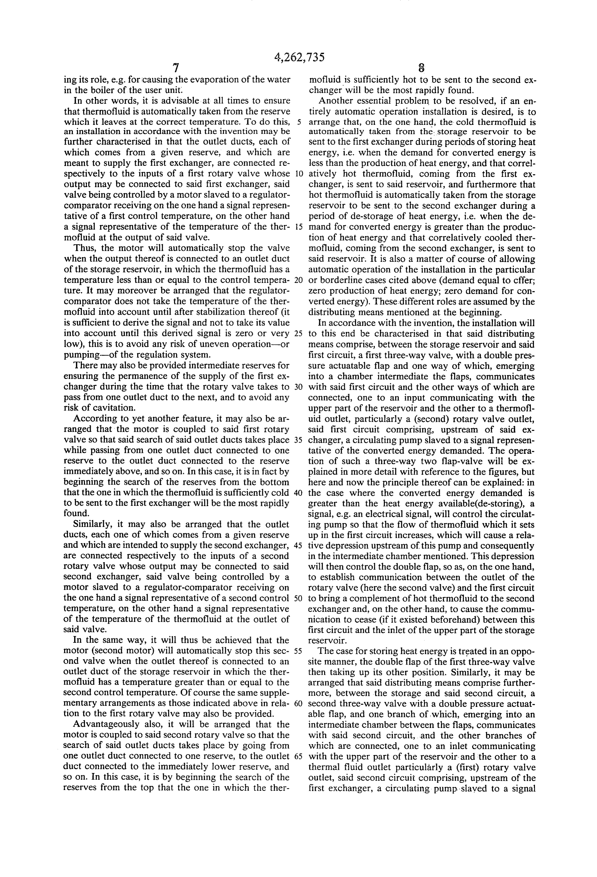
It will be readily understood that this second three At 16, there is shown a condenser supplied by a cold way valve operates similarly to the first one. , water source 17 and returning, after condensation, the Thus, to only take up again here a case of operation in steam coming from engine 12 into heating coils 10, in correlation with what has been described above (de accordance with a conventional heat cycle. Reference storage), to a depression created by this circulating 18 designates the outlet for the water heater in con pump in the intermediate chamber of the first three-way denser 16 (heat cast-offs), valve will correspond a relative over-pressure in the As to the output 19 of the second exchanger 8, it is intermediate chamber of the second three-way valve. 10 connected to input 20 of the first exchanger 1 by second This valve is of course then arranged so that its double circuit 21 comprising another circulating pump 22 and a flap takes up a position allowing a connection between pressure accumulator 23, also forming a reserve, ensur the second circuit and the inlet of the upper part of the ing that a minimum flow of thermofluid always passes heat storage reservoir, so that a part of the thermofluid through the first exchanger 1. This thermofluid is for cooled in the second exchanger may be re-heated 15 example fluid known commercially under the name therein and prohibiting moreover, (if it existed before "Gilotherm', and its temperature at the output 3 must hand) communication between this second circuit and not exceed about 350° C., failing which it could un the outlet of the rotary valve (here the first valve). Here dergo cracking.
again, the case of heat storage will be treated in an In accordance with the invention, a heat storage opposite manner, the double flap of the second three reservoir 24 having several levels or tiered storage com way valve then taking up its other position. Other types partments 25 is connected between the first circuit 5 and of distributing means could be provided, using for ex the second circuit 21. This connection is achieved ample a subsidiary reservoir with two insulated com through two three-way double-flap valves, shown sche partments disposed at the upper part of the storage matically at 26 and 27 in the following way: One branch reservoir. Such a variation will only be described with 25 28 of first valve 26 is connected to the first circuit 5; reference to the figures. another branch 29 of this valve is connected to a ther DETALED DESCRIPTION OF THE mofluid inlet 30 at the upper part of heat storage reser DRAWINGS AND THE PREFERRED voir 24; and the third branch 31 of this valve is con EMBODIMENTS nected to the outlet 32 of a rotary valve shown schemat ically at 33, and whose inlets (not shown in FIG. 1) are
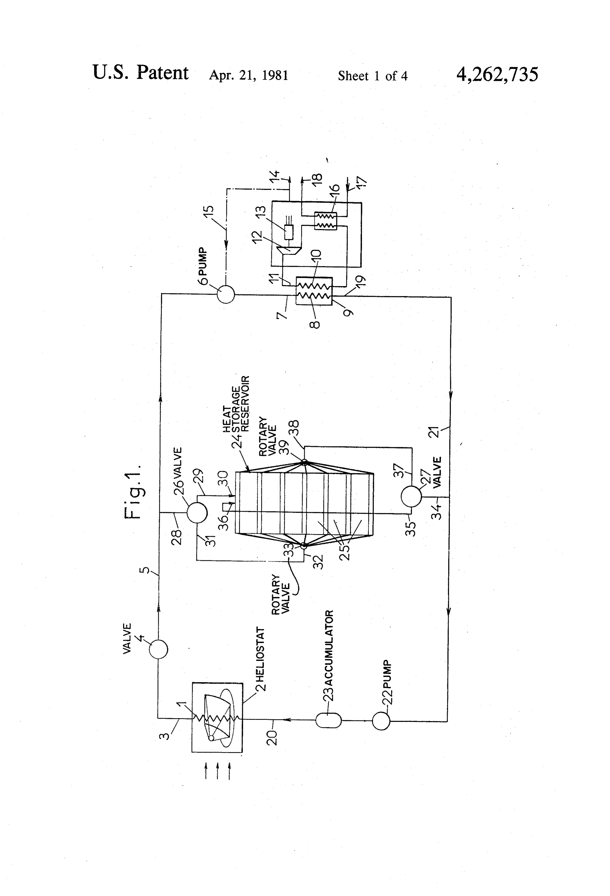
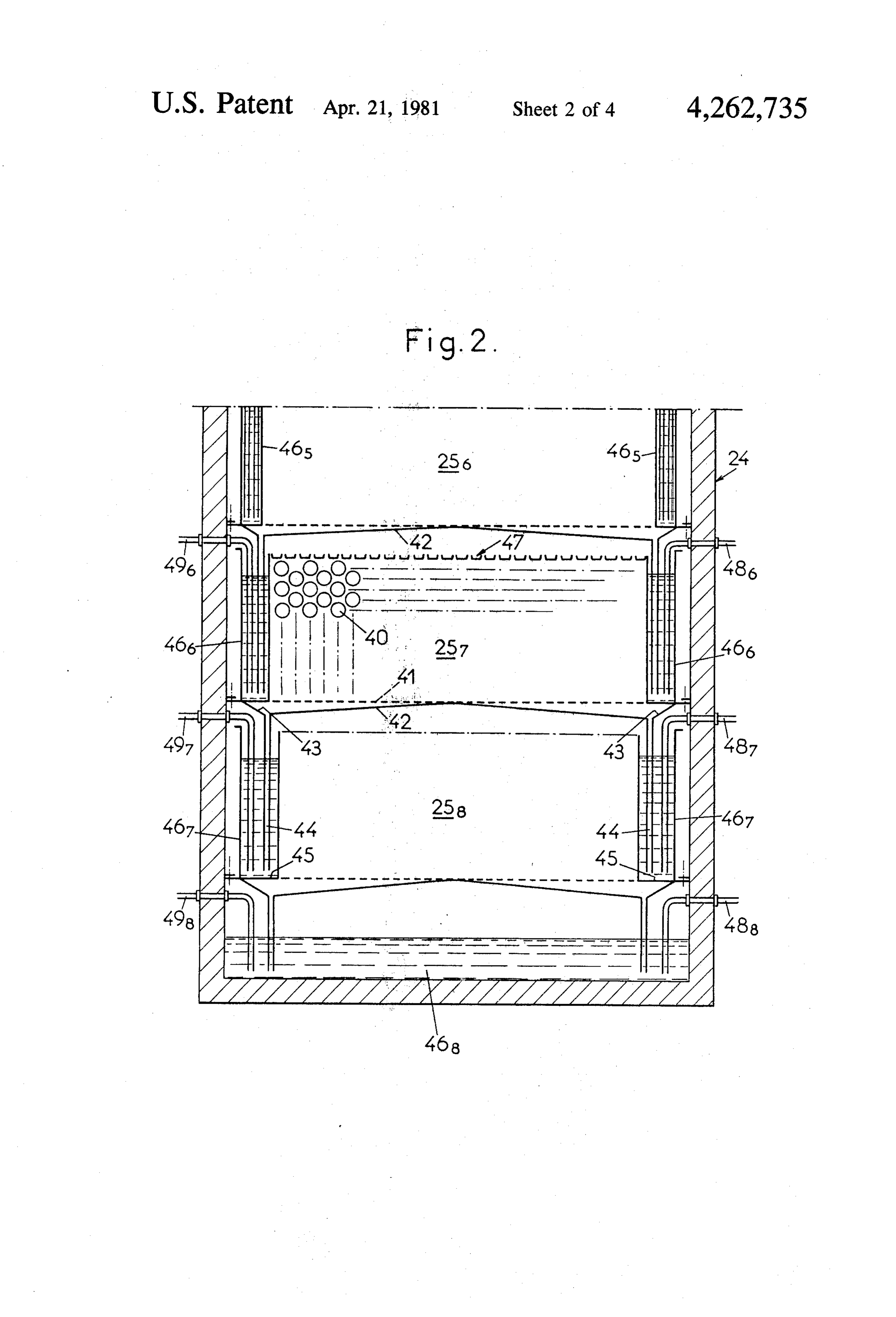
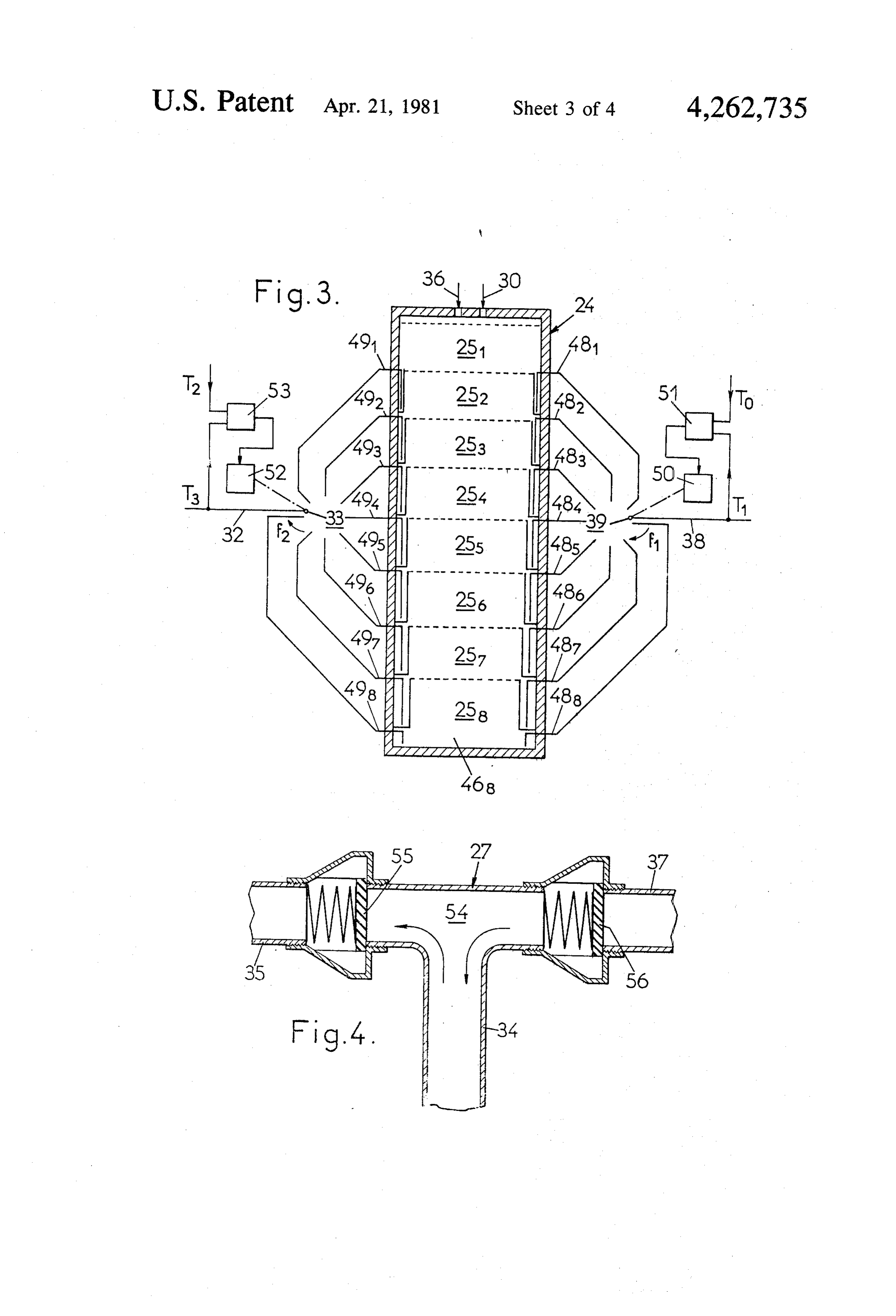
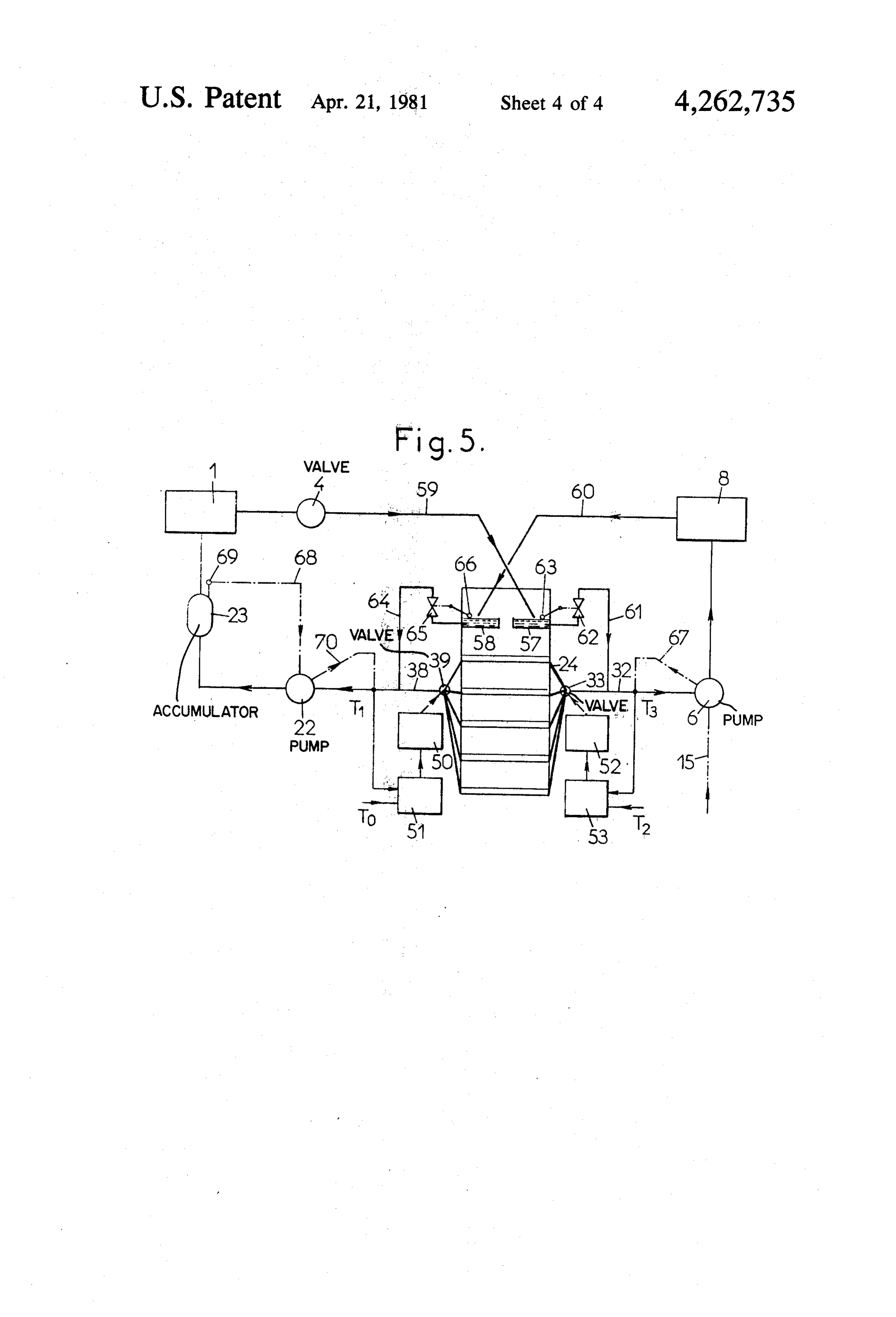
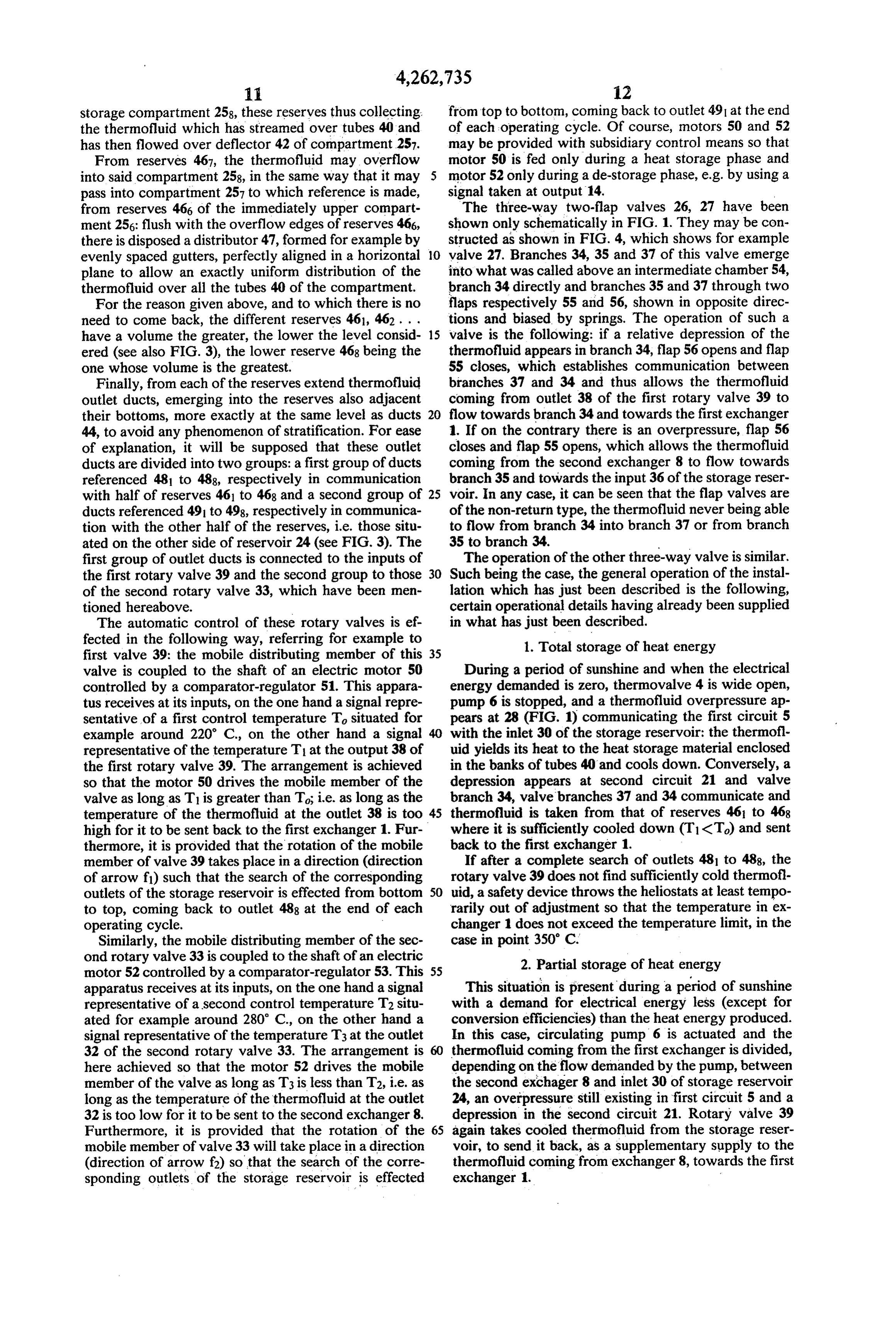
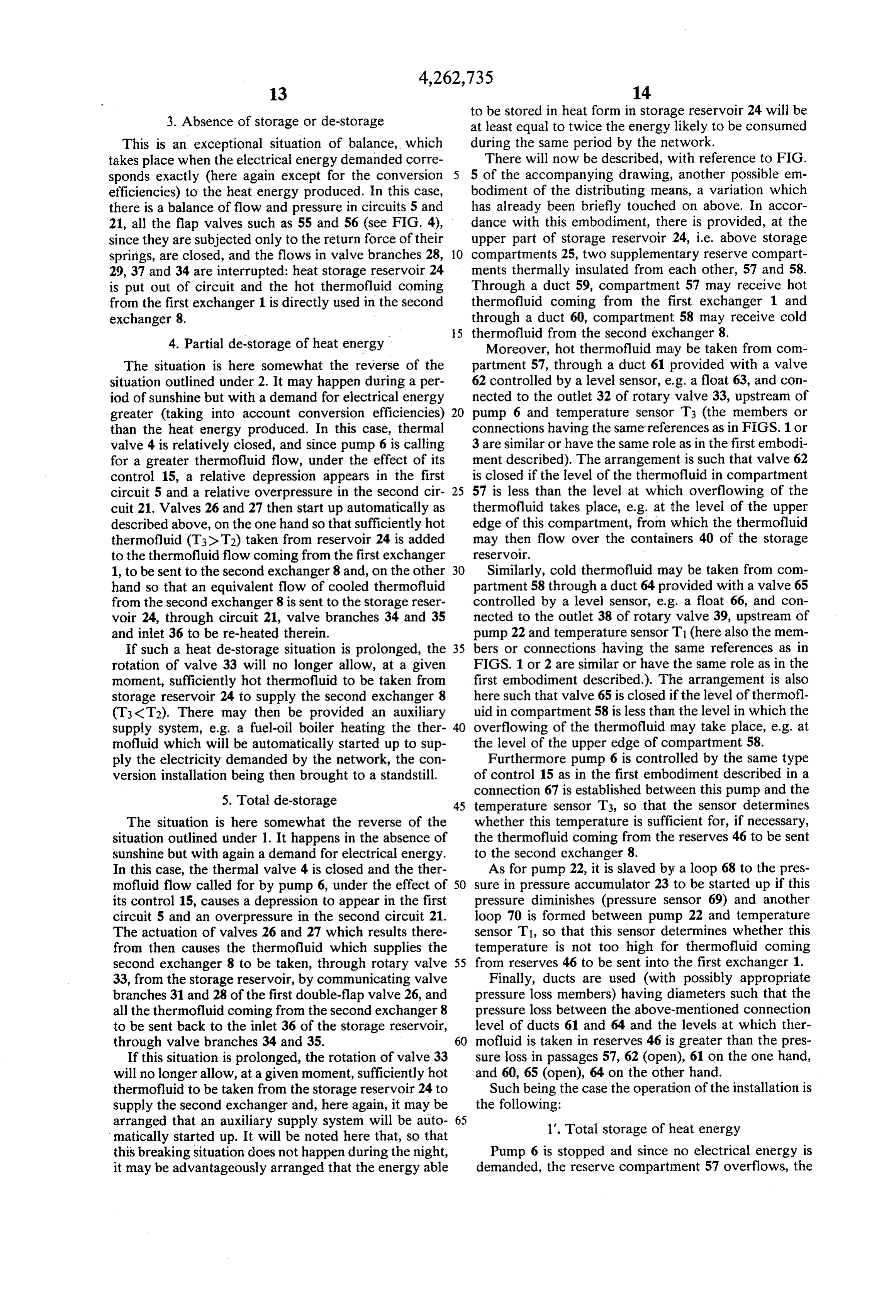
An installation for storing and recovering heat en connected respectively to different levels 25 of reser ergy in accordance with the invention, particularly for voir 24, as will be better seen in detail hereafter. a solar power station, is described in more detail below, Similarly, one branch 34 of the second three-way with reference to the figures of the accompanying valve 27 is connected to the second circuit 21; another drawings in which: 35 branch 35 of this valve is connected to another ther FIG. 1 is a schematic overall view of an installation in mofluid inlet 36 at the upper part of reservoir 24; and accordance with the invention; the third way 37 of this valve is connected to the outlet FIG. 2 is a partial elevation view in axial section of a 38 of another rotary valve shown schematically at 39, heat storage reservoir usable in the installation of FIG. and whose inlets (not shown either in FIG. 1) are also 1: : 40 connected respectively to the different levels 25 of stor FIG. 3 is a schematical view of the storage reservoir age reservoir 24. The first valve 26 and the second valve showing the organisation and the automatic control of 27 form, in this embodiment, what has been called "dis the two rotary valves for taking thermofluid from the tributing means'.
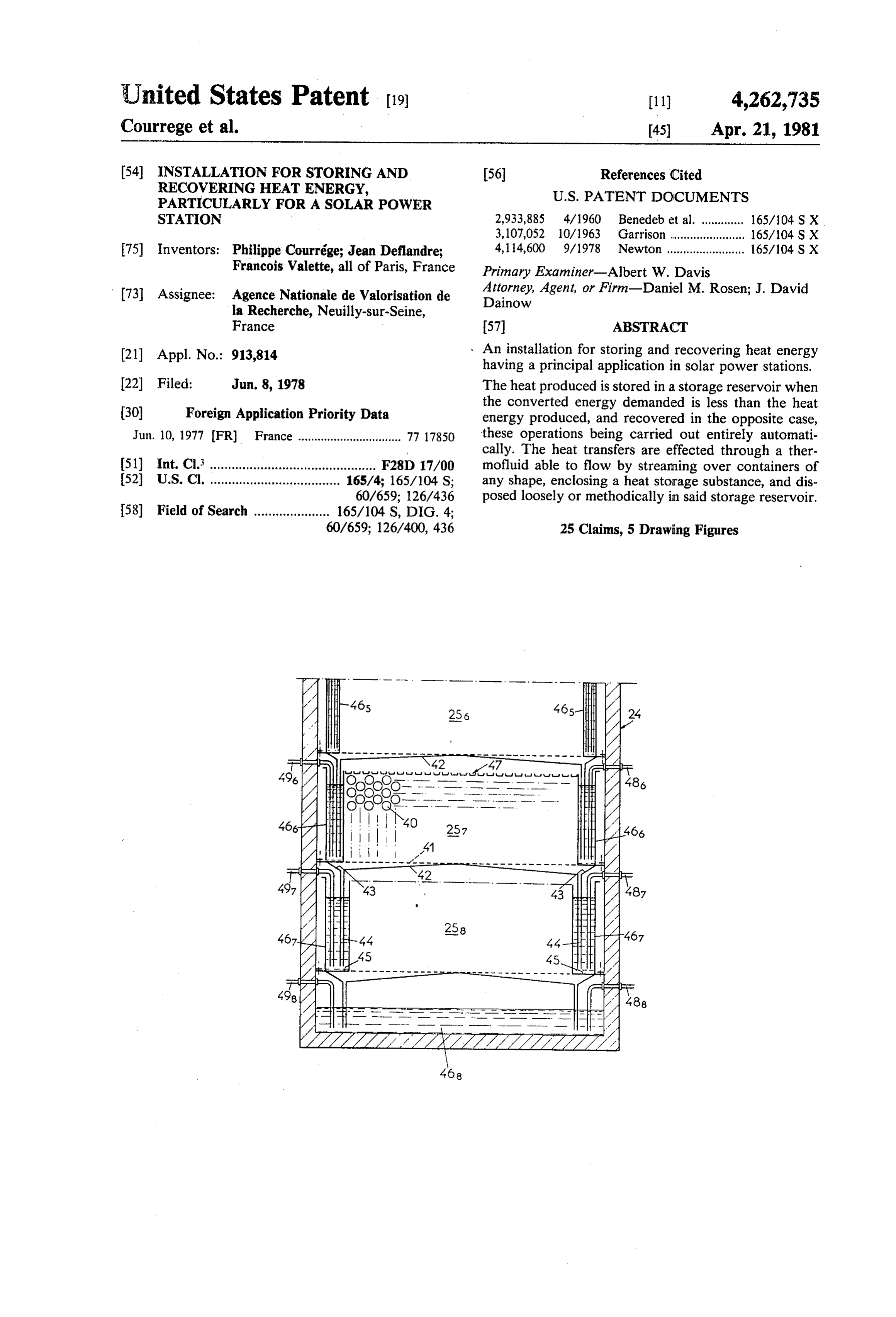
reservoir; In FIG. 2 there is only shown the lower part of the FIG. 4 is a partial schematic and sectional view of a 45 heat storage reservoir 24, so as to simplify the drawing. three-way double-flap valve for forming means for This reservoir can have for example the shape of a distributing the thermofluid; and rectangular based tower extending essentially upwards. FIG. 5 is another schematical overall view of an It is divided for example into eight levels the lower installation in accordance with the invention showing a three of which only appear in FIG. 2. Since these levels modification of the distributing means. 50 are essentially identical, reference will only be made to The installation shown in FIG. 1 shows, as a first one of them, e.g. the second from the last. exchanger, forming a heat source, a system of heating This level comprises a heat storage compartment 257 coils or boilers, reference at 1 and on which are directed in which are superposed banks of horizontal tubes 40 the sun's rays, through a system of swivelling mirrors. disposed for example alternately so that even passages This system is shown schematically at 2 (heliostats). 55 are provided between them from top to bottom of the The outlet 3 of the first exchanger 1 is connected, compartment. These tubes 40 are closed and contain a through a thermo-valve 4, to a first circulation circuit 5 heat storage material melting at a temperature within itself connected, through a circulating pump 6, to the the range of temperatures able to be reached normally inlet 7 of an exchanger 8. This second exchanger forms by the Gilotherm; for this purpose, as indicated above, part of a boiler 9 provided with a system of heating coils 60 soda may be chosen.
10 in heat connection with the second exchanger 8 and Instead of tubes 40, the soda could be enclosed in through which water flows. Steam coming from 11 of metal boxes loosely stacked in the compartment, on a the heating coils 10 supplies a turbine or piston steam perforated bottom or grid 41 thereof. Underneath grid engine 12 driving an electricity generator 13. Reference 41 is disposed a deflector in the form of a double pitch 14 designates symbolically the output of converted 65 roof 42, whose side edges are in the shape of funnels 43 energy produced by the installation. An electrical signal extended downwards by inlet pipes 44. These pipes representative of the electrical energy demanded gov emerge adjacent the bottoms 45 of two lateral reserves erns, through a control circuit 15, circulating pump 6, 467 disposed on each side of the immediately lower
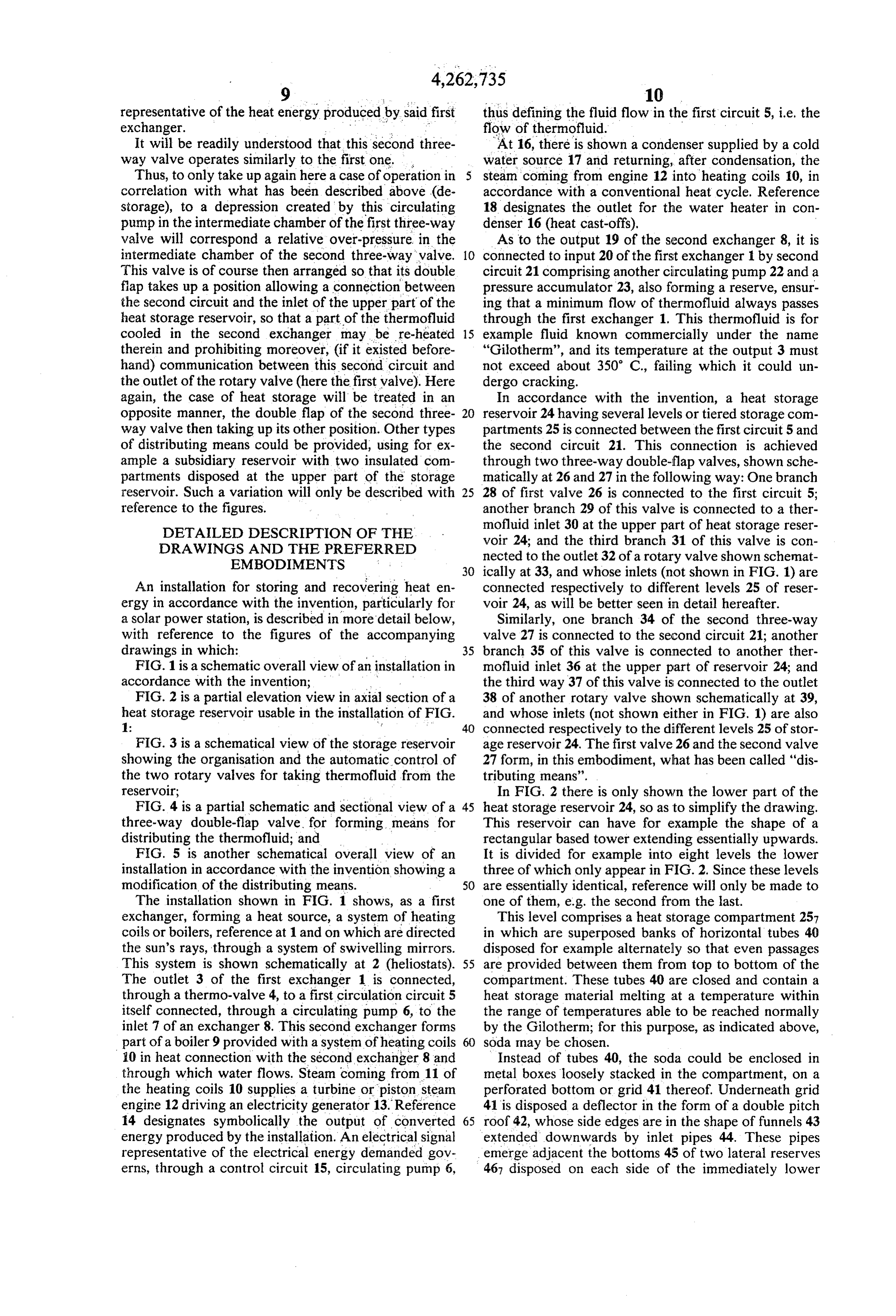
Page 11
storage compartment 258, these reserves thus collecting from top to bottom, coming back to outlet 491 at the end the thermofluid which has streamed over tubes 40 and of each operating cycle. Of course, motors 50 and 52 has then flowed over deflector 42 of compartment 257. may be provided with subsidiary control means so that From reserves 467, the thermofluid may overflow motor 50 is fed only during a heat storage phase and into said compartment 258, in the same way that it may motor 52 only during a de-storage phase, e.g. by using a pass into compartment 257 to which reference is made, signal taken at output 14.
from reserves 466 of the immediately upper compart The three-way two-flap valves 26, 27 have been ment 256: flush with the overflow edges of reserves 466, shown only schematically in FIG. 1. They may be con there is disposed a distributor 47, formed for example by structed as shown in FIG. 4, which shows for example evenly spaced gutters, perfectly aligned in a horizontal 10 valve 27. Branches 34, 35 and 37 of this valve emerge plane to allow an exactly uniform distribution of the into what was called above an intermediate chamber 54, thermofluid over all the tubes 40 of the compartment. branch 34 directly and branches 35 and 37 through two For the reason given above, and to which there is no flaps respectively 55 and 56, shown in opposite direc need to come back, the different reserves 461, 462 . . . tions and biased by springs. The operation of such a have a volume the greater, the lower the level consid 15 valve is the following: if a relative depression of the ered (see also FIG. 3), the lower reserve 468 being the thermofluid appears in branch34, flap 56 opens and flap one whose volume is the greatest. 55 closes, which establishes communication between Finally, from each of the reserves extend thermofluid branches 37 and 34 and thus allows the thermofluid outlet ducts, emerging into the reserves also adjacent coming from outlet 38 of the first rotary valve 39 to their bottoms, more exactly at the same level as ducts 20 flow towards branch 34 and towards the first exchanger 44, to avoid any phenomenon of stratification. For ease 1. If on the contrary there is an overpressure, flap 56 of explanation, it will be supposed that these outlet closes and flap 55 opens, which allows the thermofluid ducts are divided into two groups: a first group of ducts coming from the second exchanger 8 to flow towards referenced 481 to 488, respectively in communication branch35 and towards the input 36 of the storage reser with half of reserves 461 to 468 and a second group of 25 voir. In any case, it can be seen that the flap valves are ducts referenced 491 to 498, respectively in communica of the non-return type, the thermofluid never being able tion with the other half of the reserves, i.e. those situ to flow from branch 34 into branch 37 or from branch ated on the other side of reservoir 24 (see FIG. 3). The 35 to branch 34. s . first group of outlet ducts is connected to the inputs of The operation of the other three-way valve is similar. the first rotary valve 39 and the second group to those 30 Such being the case, the general operation of the instal of the second rotary valve 33, which have been men lation which has just been described is the following, tioned hereabove. certain operational details having already been supplied The automatic control of these rotary valves is ef in what has just been described.
fected in the following way, referring for example to 1. Total storage of heat energy first valve 39; the mobile distributing member of this 35 valve is coupled to the shaft of an electric motor 50 During a period of sunshine and when the electrical controlled by a comparator-regulator 51. This appara energy demanded is zero, thermovalve 4 is wide open, tus receives at its inputs, on the one hand a signal repre pump 6 is stopped, and a thermofluid overpressure ap sentative of a first control temperature To situated for pears at 28 (FIG. 1) communicating the first circuit 5 example around 220 C., on the other hand a signal 40 with the inlet 30 of the storage reservoir; the thermofl representative of the temperature T at the output 38 of uid yields its heat to the heat storage material enclosed the first rotary valve 39. The arrangement is achieved in the banks of tubes 40 and cools down. Conversely, a so that the motor 50 drives the mobile member of the depression appears at second circuit 21 and valve valve as long as T1 is greater than To; i.e. as long as the branch 34, valve branches 37 and 34 communicate and temperature of the thermofluid at the outlet 38 is too 45 thermofluid is taken from that of reserves 461 to 468 high for it to be sent back to the first exchanger 1. Fur where it is sufficiently cooled down (T. CT) and sent thermore, it is provided that the rotation of the mobile back to the first exchanger 1.
member of valve 39 takes place in a direction (direction If after a complete search of outlets 481 to 488, the of arrow f) such that the search of the corresponding rotary valve 39 does not find sufficiently cold thermofl outlets of the storage reservoir is effected from bottom 50 uid, a safety device throws the heliostats at least tempo to top, coming back to outlet 488 at the end of each rarily out of adjustment so that the temperature in ex operating cycle. changer 1 does not exceed the temperature limit, in the Similarly, the mobile distributing member of the sec case in point 350° C.
ond rotary valve 33 is coupled to the shaft of an electric 2. Partial storage of heat energy motor 52 controlled by a comparator-regulator 53. This 55 apparatus receives at its inputs, on the one hand a signal This situation is present during a period of sunshine representative of a second control temperature T2 situ with a demand for electrical energy less (except for ated for example around 280 C., on the other hand a conversion efficiencies) than the heat energy produced. signal representative of the temperature T3 at the outlet In this case, circulating pump 6 is actuated and the 32 of the second rotary valve 33. The arrangement is thermofluid coming from the first exchanger is divided, here achieved so that the motor 52 drives the mobile depending on the flow demanded by the pump, between member of the valve as long as T3 is less than T2, i.e. as the second exchager 8 and inlet 30 of storage reservoir long as the temperature of the thermofluid at the outlet 24, an overpressure still existing in first circuit 5 and a 32 is too low for it to be sent to the second exchanger 8, depression in the second circuit 21. Rotary valve 39 Furthermore, it is provided that the rotation of the again takes cooled thermofluid from the storage reser mobile member of valve 33 will take place in a direction voir, to send it back, as a supplementary supply to the (direction of arrow f) so that the search of the corre thermofluid coming from exchanger 8, towards the first sponding outlets of the storage reservoir is effected exchanger 1.
Page 12
3. Absence of storage or de-storage to be stored in heat form in storage reservoir 24 will be at least equal to twice the energy likely to be consumed
This is an exceptional situation of balance, which during the same period by the network.
takes place when the electrical energy demanded corre There will now be described, with reference to FIG. sponds exactly (here again except for the conversion 5 of the accompanying drawing, another possible em efficiencies) to the heat energy produced. In this case, bodiment of the distributing means, a variation which there is a balance of flow and pressure in circuits 5 and has already been briefly touched on above. In accor 21, all the flap valves such as 55 and 56 (see FIG. 4), dance with this embodiment, there is provided, at the since they are subjected only to the return force of their upper part of storage reservoir 24, i.e. above storage springs, are closed, and the flows in valve branches 28, O compartments 25, two supplementary reserve compart 29, 37 and 34 are interrupted: heat storage reservoir 24 ments thermally insulated from each other, 57 and 58. is put out of circuit and the hot thermofluid coming Through a duct 59, compartment 57 may receive hot from the first exchanger 1 is directly used in the second thermofluid coming from the first exchanger 1 and exchanger 8. through a duct 60, compartment 58 may receive cold 5 thermofluid from the second exchanger 8.
4. Partial de-storage of heat energy Moreover, hot thermofluid may be taken from com The situation is here somewhat the reverse of the partment 57, through a duct 61 provided with a valve situation outlined under 2. It may happen during a per 62 controlled by a level sensor, e.g. a float 63, and con iod of sunshine but with a demand for electrical energy nected to the outlet 32 of rotary valve 33, upstream of greater (taking into account conversion efficiencies) 20 pump 6 and temperature sensor T3 (the members or than the heat energy produced. In this case, thermal connections having the same references as in FIGS. 1 or valve 4 is relatively closed, and since pump 6 is calling 3 are similar or have the same role as in the first embodi for a greater thermofluid flow, under the effect of its ment described). The arrangement is such that valve 62 control 15, a relative depression appears in the first is closed if the level of the thermofluid in compartment circuit 5 and a relative overpressure in the second cir 25 57 is less than the level at which overflowing of the cuit 21. Valves 26 and 27 then start up automatically as thermofluid takes place, e.g. at the level of the upper described above, on the one hand so that sufficiently hot edge of this compartment, from which the thermofluid thermofluid (T3) T2) taken from reservoir 24 is added may then flow over the containers 40 of the storage to the thermofluid flow coming from the first exchanger reservoir.
1, to be sent to the second exchanger 8 and, on the other 30 Similarly, cold thermofluid may be taken from com hand so that an equivalent flow of cooled thermofluid partment 58 through a duct 64 provided with a valve 65 from the second exchanger 8 is sent to the storage reser controlled by a level sensor, e.g. a float 66, and con voir 24, through circuit 21, valve branches 34 and 35 nected to the outlet 38 of rotary valve 39, upstream of and inlet 36 to be re-heated therein. pump 22 and temperature sensor T1 (here also the mem If such a heat de-storage situation is prolonged, the 35 bers or connections having the same references as in rotation of valve 33 will no longer allow, at a given FIGS. 1 or 2 are similar or have the same role as in the moment, sufficiently hot thermofluid to be taken from first embodiment described.). The arrangement is also storage reservoir 24 to supply the second exchanger 8 here such that valve 65 is closed if the level of thermofl (T3<T2). There may then be provided an auxiliary uid in compartment 58 is less than the level in which the supply system, e.g. a fuel-oil boiler heating the ther 40 overflowing of the thermofluid may take place, e.g. at mofluid which will be automatically started up to sup the level of the upper edge of compartment 58. ply the electricity demanded by the network, the con Furthermore pump 6 is controlled by the same type version installation being then brought to a standstill. of control 15 as in the first embodiment described in a 5. Total de-storage connection 67 is established between this pump and the 45 temperature sensor T3, so that the sensor determines
The situation is here somewhat the reverse of the whether this temperature is sufficient for, if necessary, situation outlined under 1. It happens in the absence of the thermofluid coming from the reserves 46 to be sent sunshine but with again a demand for electrical energy. to the second exchanger 8.
In this case, the thermal valve 4 is closed and the ther As for pump 22, it is slaved by a loop 68 to the pres mofluid flow called for by pump 6, under the effect of 50 sure in pressure accumulator 23 to be started up if this its control 15, causes a depression to appear in the first pressure diminishes (pressure sensor 69) and another circuit 5 and an overpressure in the second circuit 21. loop 70 is formed between pump 22 and temperature The actuation of valves 26 and 27 which results there sensor T1, so that this sensor determines whether this from then causes the thermofluid which supplies the temperature is not too high for thermofluid coming second exchanger 8 to be taken, through rotary valve 55 from reserves 46 to be sent into the first exchanger 1. 33, from the storage reservoir, by communicating valve Finally, ducts are used (with possibly appropriate branches 31 and 28 of the first double-flap valve 26, and pressure loss members) having diameters such that the all the thermofluid coming from the second exchanger 8 pressure loss between the above-mentioned connection to be sent back to the inlet 36 of the storage reservoir, level of ducts 61 and 64 and the levels at which ther through valve branches 34 and 35. 60 mofluid is taken in reserves 46 is greater than the pres If this situation is prolonged, the rotation of valve 33 sure loss in passages 57, 62 (open), 61 on the one hand, will no longer allow, at a given moment, sufficiently hot and 60, 65 (open), 64 on the other hand. thermofluid to be taken from the storage reservoir 24 to Such being the case the operation of the installation is supply the second exchanger and, here again, it may be the following:
arranged that an auxiliary supply system will be auto 65 1'. Total storage of heat energy matically started up. It will be noted here that, so that this breaking situation does not happen during the night, Pump 6 is stopped and since no electrical energy is it may be advantageously arranged that the energy able demanded, the reserve compartment 57 overflows, the
Page 13
hot thermofluid flows into the heat storage compart which it overflows into the different storage compart ments 25 of reservoir 24, where it is cooled. Since valve ments of the reservoir to be re-heated therein. Here 65 is closed, and since the level in reserve 58 is too low, again, if this situation is too prolonged and if the search there reigns a relative depression in pressure accumula of the reserves by valve 38 cannot find sufficiently hot tor 23, which, through loop 68, controls the starting up thermofluid, the conversion installation is stopped or of pump 22 and the temperature control system T1. the thermofluid is heated by an auxiliary boiler, e.g. Rotary valve 39 (whose inlets are connected, in a way working on fuel-oil.
not shown in FIG. 5, but in the same way as in the first As is evident and as it follows already moreover from embodiment described, to reserves 461 to 468) estab what has gone before, the invention is in no wise limited lishes the connection, being automatically controlled by 10 to those of its modes of application and embodiments motor 50 and regulator 51, between its outlet 38 and which have been more especially considered; it em that of its outlet which is connected to the reserve in braces, on the contrary, all variations thereof. which the thermofluid is sufficiently cold (TCT) to We claim:
be sent back to the first exchanger . 1. An installation for storing and recovering heat Of course, here again, if this situation were too pro 15 energy, particularly for a solar power station, compris longed and if rotary valve 39 could no longer find suffi ing: a first exchanger, associated with a heat source, in ciently cold thermofluid in reserves 46, it could be ar which a circulating heat-carrying fluid or thermofluid ranged for the heliostats to be put out of adjustment (or may undergo a temperature increase; a second ex to start up the conversion system). changer in which said thermofluid may yield heat to a
2". Partial storage of heat energy user unit; a first circuit connecting the outlet of the first In this case, since valve 62 is open, and because re connectingtothetheoutlet exchanger inlet of the second; a second circuit of the second exchanger to the serve 57 is overflowing, the hot thermofluid supplying inlet of the first; a storage reservoir containing a heat the second exchanger 8 is taken solely from this reserve storage material capable of storing heat, connected both 57 since an over abundance of thermofluid arrives 25 therein from the first exchanger 1, the surplus continu means for automatically effecting a givenanddistribution to the first circuit and to the second; distributing
ing to flow into the storage compartments 25 of reser either the thermofluid coming from the first exchanger voir 24 to be cooled down therein; the rotary valve 33 between the second exchanger and the storage reser is then stopped. Moreover, since the flow in duct 60 is voir, or the thermofluid coming from the second ex less than the flow in duct 59, reserve 58 is not sufficient 30 to supply the first exchanger 1 with cold thermofluid changer means between the first exchanger and said reservoir;
for streaming said thermofluid over the walls and the complement must be supplied by rotary valve 39, operating as in case 1". of containers enclosing said heat storage material and which are disposed in said storage reservoir;
3. Absence of storage or de-storage 35 and
This corresponds to an equality of thermofluid flow wherein said storage reservoir comprises several su inducts 59 and 60. Only reserves 57 and 58 are in action perposed compartments or levels, each of which is and the state of the storage reservoir does not change; provided with a thermofluid reserve collecting the reserves 57 and 58 do not overflow and receive exactly thermofluid which has streamed over the contain the same amount of thermofluid as that which is taken ers of the compartment considered and from therefrom. Rotary valves 33 and 39 are then stopped. which, the thermofluid may either be taken through at least one outlet duct, to be directed 4. Partial de-storage of heat energy either towards the first exchanger or towards the In this situation, the thermofluid flow in duct 60 is second, or this thermofluid may flow, particularly greater than the thermofluid flow in duct 59, and re 45 by overflowing, towards the level situated immedi serve 57 is not sufficient to supply second exchanger 8 ately below the level considered, by streaming with hot thermofluid. Rotary valve 33 is started up and over the containers of heat storage material of said takes from that of reserves 46 where it is hot enough level situated below.
(T3) T2) complementary thermofluid to send it to the 2. An installation according to claim 1, wherein said second exchanger 8. The operation of this valve is the 50 storage reservoir extends essentially vertically and same as in the case of the first embodiment described. If wherein said material capable of storing heat, formed this situation is too prolonged, T3 becomes lower than particularly of a meltable substance or similar, con the control temperature T2 and an auxiliary installation tained in said storage reservoir, is distributed in an as must then be started up, as in the case of situation 4 seen sembly of containers whose individual volume is small above. 55 with respect to the total volume of said material, these As to reserve 48, it is overflowing and it is sufficient containers being superposed in said reservoir, substan to supply the first exchanger 1 with cold thermofluid, tially over its height, so that spaces are provided there through valve 65, then open. Rotary valve 39 is then between, in order to let said thermofluid pass from the stopped; the surplus of cold thermofluid overflows and upper part to the lower part of said reservoir. flows, to be re-heated, in storage compartments 25 of 60 3. An installation according to claim 2 wherein said reservoir 24. containers are boxes or cans, of the kind used for food preservation or similar, particularly cylindrical, stacked 5'. Total de-storage loosely or methodically in said reservoir.
Since the flow in duct 59 is zero, valve 62 is closed 4. An installation according to claim 2 wherein said and all the thermofluid supplying the second exchanger 65 containers are formed from horizontal spaced tubes, or 8 is taken, through rotary valve 33, from reserves 46 of cylindrical boxes aligned so as to form overall horizon storage reservoir 24. The cooled thermofluid returns, tal tubes, these tubes being spread out in superposed and through duct 60, to reserve compartment 58, from alternately disposed layers. : m
Page 14
5. An installation according to claim 1, wherein said duct connected to the reserve immediately thereabove, storage reservoir has a circular section, said reserve of and so on, coming back to the first duct. each level is annular and surrounds, substantially over 16. An installation according to claims 1, 5 or 6, the whole of its height, the storage compartment of the wherein the outlet ducts, each of which comes from a level situated immediately below, which contains a part given reserve, and which are intended to supply the of said heat storage material containers. second exchanger, are connected respectively to the 6. An installation according to claim 1, wherein said inlets of a second rotary valve whose outlet may be storage reservoir has a square or rectangular section, connected to said second exchanger, said valve being said reserve of each level being formed by two gutters. commanded by a motor controlled by a regulator-com disposed on each side of the storage compartment of the 10 parator receiving and comparing a signal representative level situated immediately below, which contains a part of a second control temperature and a signal representa of said heat storage material containers and extends tive of the temperature of the thermofluid at the outlet substantially over the same height. of said valve.
7. An installation according to claims 1, 5, or 6, 17. An installation according to claim 16, wherein the wherein the bottom of each storage compartment is 15 motor formed by grid means for retaining the heat storage search isofcoupledsaid to said second rotary valve so that the outlet ducts takes place by passing from material containers of the level considered and for al an outlet duct connected to one reserve, to the outlet lowing a free flow of the thermofluid streaming over duct connected to the reserve immediately below, and said containers towards the reserve of said considered level. 20 so on, coming back to the first duct. 8. An installation according to claim 7, wherein wherein 18. An installation according to claims 1, 5 or 6, below said grid means of each level there is disposed a storage the distributing means comprise, between the downwardly sloping deflector means for directing the able three-branchanddouble-flap reservoir said first circuit, a pressure actuat valve, one branch of thermofluid having streamed over the containers of the which, emerging into an intermediate chamber between storage compartment of the level considered towards 25 the reserve of said level. the flaps, communicates with said first circuit and the 9. An installation according to claim 8, wherein the other branches of which are connected, one to an inlet edges of said deflector means are formed in the shape of communicating with the upper part of the reservoir, a funnel extended downwards by an inlet pipe emerging and therotary other to a thermofluid outlet, particularly a adjacent the bottom of the reserve of the level consid 30 second valve outlet, said first circuit comprising, upstream of the second exchanger, a circulating pump ered.
10. An installation according to claim 9, wherein the slaved to a signal representative of the converted en outlet ducts which allow thermofluid to be taken from ergy demanded.
the reserve of one level to direct it either to the first 19. An installation according to claims 1, 5 or 6, exchanger or to the second, emerge into said reserve 35 wherein the distributing means comprise furthermore, substantially adjacent to, and at the same level as, the between the storage reservoir of said second circuit, a inlet pipes. second pressure actuatable three-branch double-flap 11. An installation according to claims 1, 5 or 6 valve, one branch of which, emerging into an interme wherein above the storage compartment of each level diate chamber between the flaps, communicates with of the storage reservoir there is disposed horizontal 40 said second circuit, and whose other branches are con distributor means for collecting the thermofluid over nected, one to an inlet communicating with the upper flowing from the reserve of the storage compartment of part of the reservoir, and the other to a thermofluid the level situated immediatly above. outlet, particularly a first rotary valve outlet, the second 12. An installation according to claims 1, 5 or 6, circuit comprising, upstream of the first exchanger, a wherein the volume of the different reserves of ther 45 circulating pump slaved to a signal representative of the mofluid of the storage reservoir is greater, the lower the heat energy produced by said first exchanger. corresponding level. 20. An installation according to claims 1, 5 or 6, 13. An installation according to claim 12, wherein the wherein the distributing means comprise two thermally volume of a thermofluid reserve of one level is at least insulated reserve compartments disposed at the upper equal to the sum of the volume of the thermofluid re 50 part of the heat storage reservoir, and from which ther serve of the level situated immediately above and of the mofluid may overflow towards the lower part of said volume of streaming thermofluid in the storage com reservoir so as to be able to exchange heat with the heat partment of the level considered. storage material, one of said compartments being 14. An installation according to claims 1, 5 or 6, adapted to receive thermofluid coming from the outlet wherein the outlet ducts, each of which comes from a 55 of the second exchanger and being able to communicate given reserve, and which are intended to supply the first with the inlet of the first exchanger through a valve, the exchanger, are connected respectively to the inlets of a other compartment being adapted to receive thermofl first rotary valve whose outlet may be connected to said uid coming from the outlet of the first exchanger and first exchanger, said valve being controlled by a motor able to communicate with the inlet of the second which motor is controlled by a regulator-comparator 60 through another valve, and wherein these valves are receiving and comparing a signal representative of a subjected to the control of a sensor of the level of ther first control temperature, and a signal representative of mofluid in the corresponding compartment, so as to be the temperature of the thermofluid at the outlet of said closed when this level is less than that at which said valve. overflowing takes place, means for circulating the ther 15. An installation according to claim 14, wherein the 65 mofluid being furthermore provided respectively be motor is coupled to said first rotary valve so that the tween the first valve mentioned and the inlet of the first search of said outlet ducts takes place by passing from exchanger and between the second valve mentioned an outlet duct connected to one reserve, to the outlet and the inlet of the second exchanger.
Page 15
21. An installation according to claim 20, wherein the 23. An installation according to claim 21, wherein the valve associated with the reserve compartment which pump connected to the inlet of the second exchanger is receives thermofluid coming from the first exchanger is slaved to a control depending on the demand for con connected to the outlet of a rotary valve whose inlets verted energy, particularly to a signal representative of communicate with tiered reserves of the heat storage the temperature at the outlet of the second exchanger. reservoir, this outlet being itself connected to the inlet 24. An installation according to claim 21, wherein the of the second exchanger through a circulating pump, pressure drop between the points at which the ducts and in that the valve associated with the reserve com connected to said valves join the outlets of the respec partment which receives thermofluid coming from the tiye rotary valves, and the levels at which thermofluid second exchanger is connected to the outlet of another 10 is taken from said tiered reserves of the heat storage rotary valve whose inlets communicate with tiered reservoir, is greater than the pressure drop in the pas reserves of the heat storage reservoir, this outlet being sages which comprise the corresponding connections itself connected to the inlet of the first exchanger between the exchangers and the associated reserve through another circulating pump. compartment, as well as the corresponding valve, con 22. An installation according to claim 21, wherein the 15 sidered open.
pump connected to the inlet of the first exchanger has a 25. An installation according to claim 14, further control slaved to a signal representative of the amount comprising a thermofluid reserve capable of avoiding of heat energy supplied by the first exchanger, particu cavitation phenomena between each rotor valve and the larly to a signal representative of the pressure of the corresponding pump. s thermofluid downstream. 20
Provenance
- Collection
- Cited prior art
- Original PDF
- patentimages.storage.googleapis.com →
- Filed
- 1978-06-08
- Pages
- 15
- Method
- pdftotext (the PDF's own text layer) + pdftoppm 300dpi page scans
- Source
- Google Patents bibliographic record
- Granted
- 1981-04-21
- Inventors
- Philippe Courrege; Jean Deflandre; Francois Valette; Agence National de Valorisation de la Recherche ANVAR
- Transcribed from
- patentimages.storage.googleapis.com →