patent · US3425402
Installation for regulating an internal combustion engine operating according to a recirculating method,especially underwater crafts
4 February 1969
Page 1
Drawing sheet — no readable text.
Page 2
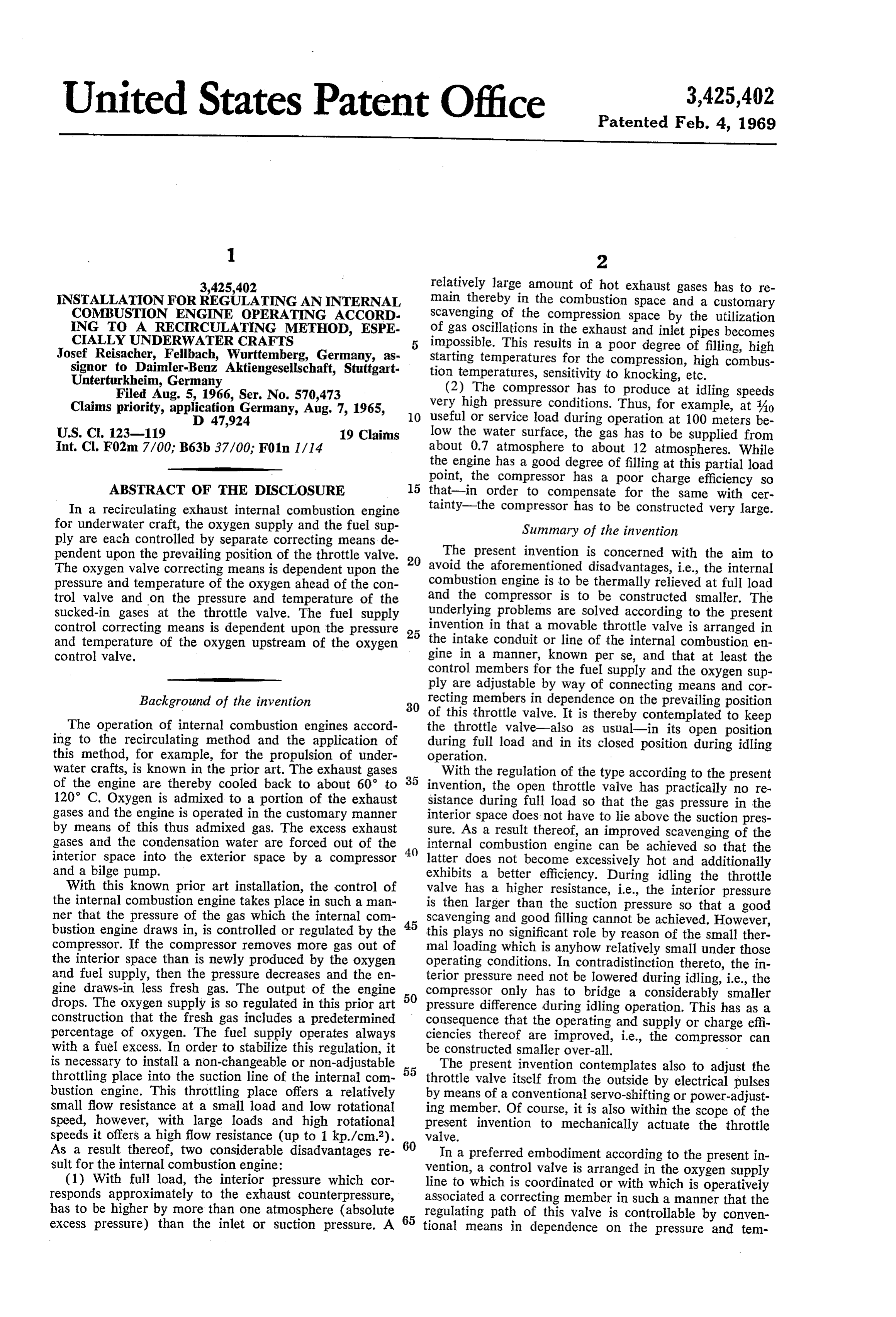
United States Patent Office 3,425,402 Patented Feb. 4, 1969
3,425,402 relatively large amount of hot exhaust gases has to re INSTALLATION FORREGULATING AN INTERNAL main thereby in the combustion space and a customary COMBUSTON ENGINE OPERATING ACCORD Scavenging of the compression space by the utilization
ING TO A RECIRCULATING METHOD, ESPE
CIALLY UNDERWATER CRAFTS
of gas oscillations in the exhaust and inlet pipes becomes
Josef Reisacher, Fellbach, Wurttemberg, Germany, as impossible. This results in a poor degree of filling, high starting temperatures for the compression, high combus signor to Daimler-Benz Aktiengesellschaft, Stuttgart tion
Unterturkheim, Germany temperatures, sensitivity to knocking, etc. Filed Aug. 5, 1966, Ser. No. 570,473 (2) The compressor has to produce at idling speeds Claims priority, application Germany, Aug. 7, 1965, 10 very high pressure conditions. Thus, for example, at Ao D 47,924 useful or service load during operation at 100 meters be
U.S. C. 123-119 19 Claims low the Water surface, the gas has to be supplied from Int, C. F02m 7/00, B63b 37/00, F01n 1/14 about 0.7 atmosphere to about 12 atmospheres. While the engine has a good degree of filling at this partial load point, the compressor has a poor charge efficiency so
ABSTRACT OF THE DISCLOSURE 15 that-in order to compensate for the same with cer In a recirculating exhaust internal combustion engine tainty-the compressor has to be constructed very large. for underwater craft, the oxygen supply and the fuel Sup Summary of the invention ply are each controlled by separate correcting means de pendent upon the prevailing position of the throttle valve. 20 The present invention is concerned with the aim to The oxygen valve correcting means is dependent upon the avoid the aforementioned disadvantages, i.e., the internal pressure and temperature of the oxygen ahead of the con combustion engine is to be thermally relieved at full load trol valve and on the pressure and temperature of the and the compressor is to be constructed smaller. The sucked-in gases at the throttle valve. The fuel supply underlying problems are solved according to the present control correcting means is dependent upon the pressure invention in that a movable throttle valve is arranged in and temperature of the oxygen upstream of the oxygen 25 the intake conduit or line of the internal combustion en control valve. gine in a manner, known per se, and that at least the control members for the fuel supply and the oxygen sup
ply are adjustable by way of connecting means and cor
Background of the invention 30 recting members in dependence on the prevailing position of this throttle valve. It is thereby contemplated to keep
The operation of internal combustion engines accord the throttle valve-also as usual-in its open position ing to the recirculating method and the application of during full load and in its closed position during idling this method, for example, for the propulsion of under operation.
water crafts, is known in the prior art. The exhaust gases With the regulation of the type according to the present of the engine are thereby cooled back to about 60 to invention, the open throttle valve has practically no re 120° C. Oxygen is admixed to a portion of the exhaust sistance during full load so that the gas pressure in the gases and the engine is operated in the customary manner interior space does not have to lie above the suction pres by means of this thus admixed gas. The excess exhaust sure. As a result thereof, an improved scavenging of the gases and the condensation water are forced out of the internal combustion engine can be achieved so that the interior space into the exterior space by a compressor 40 latter does not become excessively hot and additionally and a bilge pump. exhibits a better efficiency. During idling the throttle With this known prior art installation, the control of valve has a higher resistance, i.e., the interior pressure the internal combustion engine takes place in such a man is then larger than the suction pressure so that a good ner that the pressure of the gas which the internal com scavenging and good filling cannot be achieved. However, bustion engine draws in, is controlled or regulated by the 45 this plays no significant role by reason of the small ther compressor. If the compressor removes more gas out of mal loading which is anyhow relatively small under those the interior space than is newly produced by the oxygen operating conditions. In contradistinction thereto, the in and fuel supply, then the pressure decreases and the en terior pressure need not be lowered during idling, i.e., the gine draws-in less fresh gas. The output of the engine compressor only has to bridge a considerably smaller drops. The oxygen supply is so regulated in this prior art 50 pressure difference during idling operation. This has as a construction that the fresh gas includes a predetermined consequence that the operating and supply or charge effi percentage of oxygen. The fuel supply operates always ciencies thereof are improved, i.e., the compressor can with a fuel excess. In order to stabilize this regulation, it be constructed smaller over-all. - is necessary to install a non-changeable or non-adjustable 55 The present invention contemplates also to adjust the throttling place into the suction line of the internal com throttle valve itself from the outside by electrical pulses bustion engine. This throttling place offers a relatively by means of a conventional servo-shifting or power-adjust small flow resistance at a small load and low rotational ing member. Of course, it is also within the scope of the speed, however, with large loads and high rotational present invention to mechanically actuate the throttle speeds it offers a high flow resistance (up to 1 kp./cm.). 60 valve.
As a result thereof, two considerable disadvantages re In a preferred embodiment according to the present in sult for the internal combustion engine: vention, a control valve is arranged in the oxygen supply (1) With full load, the interior pressure which cor line to which is coordinated or with which is operatively responds approximately to the exhaust counterpressure, associated a correcting member in such a manner that the has to be higher by more than one atmosphere (absolute 65 regulating path of this valve is controllable by conven excess pressure) than the inlet or suction pressure. A tional means in dependence on the pressure and tem
Page 3
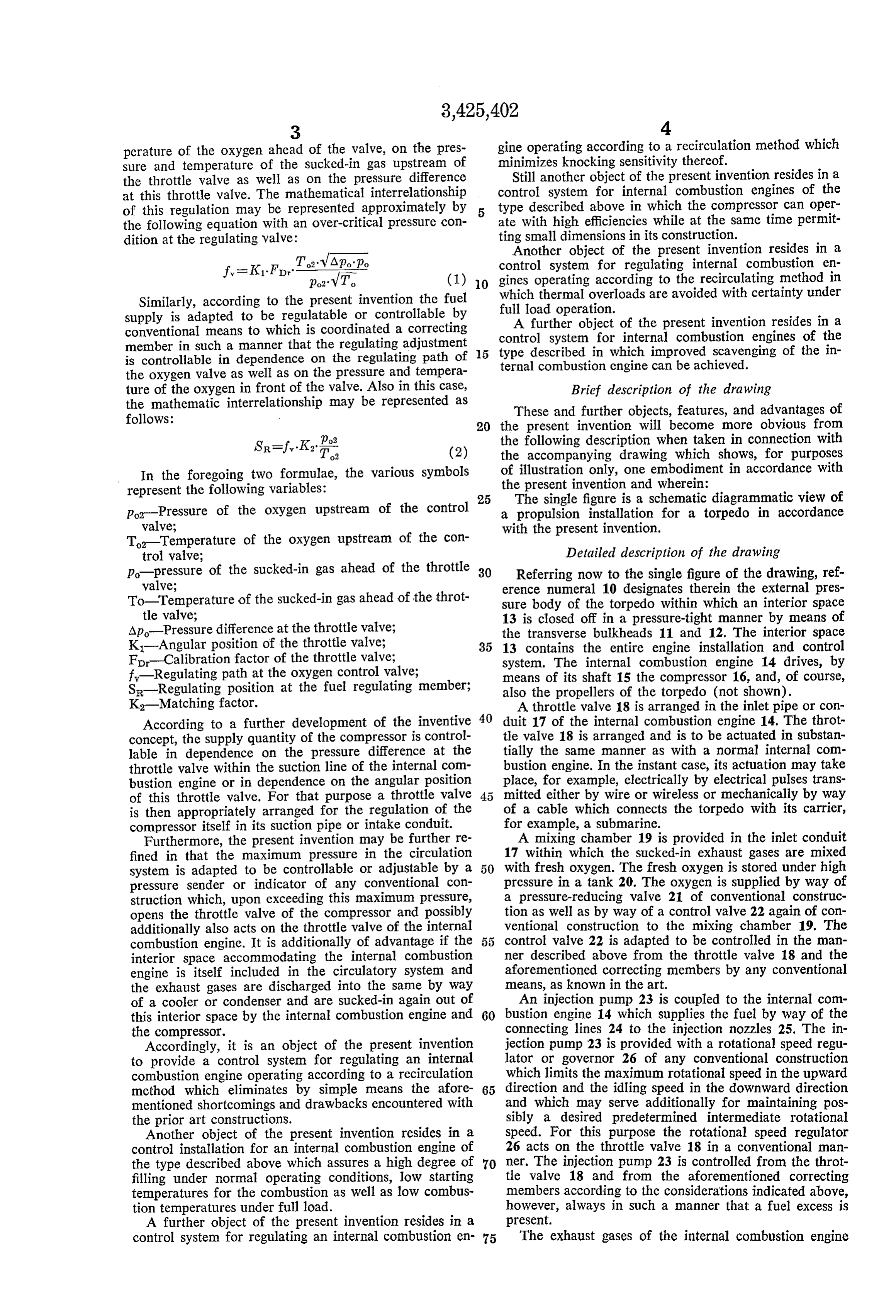
perature of the oxygen ahead of the valve, on the pres: gine operating according to a recirculation method which sure and temperature of the sucked-in gas upstream of minimizes knocking sensitivity thereof, the throttle valve as well as on the pressure difference Still another object of the present invention resides in a at this throttle valve. The mathematical interrelationship control system for internal combustion engines of the of this regulation may be represented approximately by type described above in which the compressor can oper the following equation with an over-critical pressure con ate with high efficiencies while at the same time permit dition at the regulating valve: ting small dimensions in its construction. Another object of the present invention resides in a
To: VApop.
f = K1. For" parvT. control system for regulating internal combustion en (1) 0 gines operating according to the recirculating method in
Similarly, according to the present invention the fuel which full thermal overloads are avoided with certainty under load operation.
supply is adapted to be regulatable or controllable by A further object of the present invention resides in a conventional means to which is coordinated a correcting member in such a manner that the regulating adjustment 15 control system for internal combustion engines of the is controllable in dependence on the regulating path of type described in which improved scavenging of the in ternal combustion engine can be achieved.
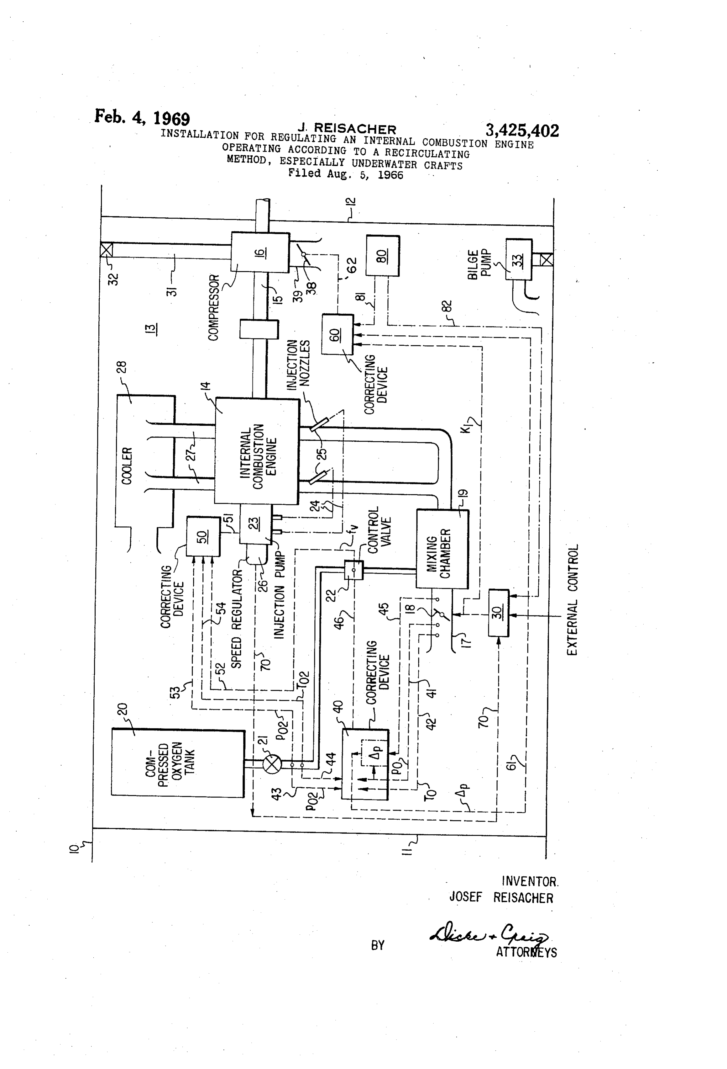
the oxygen valve as well as on the pressure and tempera ture of the oxygen in front of the valve. Also in this case, Brief description of the drawing the mathematic interrelationship may be represented as These and further objects, features, and advantages of follows: 20 the present invention will become more obvious from
SR=fy. K2 T2 (2) the following description when taken in connection with the accompanying drawing which shows, for purposes
In the foregoing two formulae, the various symbols ofthe illustration only, one embodiment in accordance with present invention and wherein:
represent the following variables: 25 The single figure is a schematic diagrammatic view of p-Pressure of the oxygen upstream of the control a propulsion installation for a torpedo in accordance valve;
T Temperature of the oxygen upstream of the con with the present invention.
trol valve; Detailed description of the drawing p-pressure of the sucked-in gas ahead of the throttle 30 Referring now to the single figure of the drawing, ref valve; erence numeral 10 designates therein the external pres To Temperature of the sucked-in gas ahead of the throt sure body of the torpedo within which an interior space tle valve; 13 is closed off in a pressure-tight manner by means of Ap-Pressure difference at the throttle valve; the transverse bulkheads 11 and 12. The interior space K-Angular position of the throttle valve; 35 13 contains the entire engine installation and control F-Calibration factor of the throttle valve; system. The internal combustion engine 14 drives, by f-Regulating path at the oxygen control valve; means of its shaft 15 the compressor 16, and, of course, S-Regulating position at the fuel regulating member; also the propellers of the torpedo (not shown). K-Matching factor. A throttle valve 18 is arranged in the inlet pipe or con According to a further development of the inventive 40 duit 17 of the internal combustion engine 14. The throt concept, the supply quantity of the compressor is control tle valve 18 is arranged and is to be actuated in substan lable in dependence on the pressure difference at the tially the same manner as with a normal internal com throttle valve within the suction line of the internal com bustion engine. In the instant case, its actuation may take bustion engine or in dependence on the angular position place, for example, electrically by electrical pulses trans of this throttle valve. For that purpose a throttle valve mitted either by wire or wireless or mechanically by way is then appropriately arranged for the regulation of the of a cable which connects the torpedo with its carrier, compressor itself in its suction pipe or intake conduit. for example, a submarine.
Furthermore, the present invention may be further re A mixing chamber 19 is provided in the inlet conduit fined in that the maximum pressure in the circulation 17 within which the sucked-in exhaust gases are mixed system is adapted to be controllable or adjustable by a 50 with fresh oxygen. The fresh oxygen is stored under high pressure sender or indicator of any conventional con pressure in a tank. 20. The oxygen is supplied by way of a pressure-reducing valve 21 of conventional construc struction which, upon exceeding this maximum pressure, opens the throttle valve of the compressor and possibly tion as well as by way of a control valve 22 again of con additionally also acts on the throttle valve of the internal ventional construction to the mixing chamber 19. The combustion engine. It is additionally of advantage if the control valve 22 is adapted to be controlled in the man interior space accommodating the internal combustion ner described above from the throttle valve 18 and the engine is itself included in the circulatory system and aforementioned correcting members by any conventional the exhaust gases are discharged into the same by way means, as known in the art.
of a cooler or condenser and are sucked-in again out of An injection pump 23 is coupled to the internal com this interior space by the internal combustion engine and 60 bustion engine 14 which supplies the fuel by way of the the compressor. connecting lines 24 to the injection nozzles 25. The in Accordingly, it is an object of the present invention jection pump 23 is provided with a rotational speed regu to provide a control system for regulating an internal lator or governor 26 of any conventional construction combustion engine operating according to a recirculation which limits the maximum rotational speed in the upward method which eliminates by simple means the afore 65 direction and the idling speed in the downward direction mentioned shortcomings and drawbacks encountered with and which may serve additionally for maintaining pos the prior art constructions. sibly a desired predetermined intermediate rotational Another object of the present invention resides in a Speed. For this purpose the rotational speed regulator control installation for an internal combustion engine of 26 acts on the throttle valve 18 in a conventional man the type described above which assures a high degree of 70 ner. The injection pump 23 is controlled from the throt filling under normal operating conditions, low starting tle valve 18 and from the aforementioned correcting temperatures for the combustion as well as low combus members according to the considerations indicated above, tion temperatures under full load. however, always in such a manner that a fuel excess is A further object of the present invention resides in a present.
control system for regulating an internal combustion en 75 The exhaust gases of the internal combustion engine
Page 4
14 are supplied by way of the exhaust pipes 27 to a jection pump 23 by way of a control linkage schematically cooler or condenser 28 and are cooled back therein to a temperature of about 60 to 120° C. The exhaust gases mechanical, electrical, hydraulic 51 indicated by reference numeral which may again be or pneumatic in nature.
leave from the cooler 28 into the interior space 13 and As input to the correcting device 50 are fed the position of are again sucked-in by the internal combustion engine the control valve 22 by means indicated schematically by out of the interior space 13 by way of the throttle valve reference numeral 52 as well as the pressure and tempera 18. The excess exhaust gases are sucked-in by the com ture of the oxygen by means schematically indicated by pressor 16 by way of its inlet conduit or pipe section reference numeral 53 and 54.
39-in which a further throttle valve 38 is provided for A still further correcting device generally designated by its regulation-and are pumped into the outside through reference numeral 60 is coordinated to the control valve the line 31 by way of a check valve 32 of conventional 30 or the compressor 16 by a linkage designated by ref. construction. A bilge pump 33 may additionally be pro erence numeral 62, again of mechanical, electrical, hy vided for the elimination of condensation water or the draulic or pneumatic nature. Fed as input to the correct like. ing device 60 by means schematically indicated by ref The throttle valve 18 in the inlet connection 17 of the 5 erence numeral 61 is the pressure difference of the gases internal combustion engine 14 is open at full load. It of Suckd-in by the internal combustion engine 14 upstream fers practically no resistance in this position so that the of the throttle valve 18 and downstream thereof. This internal pressure within the interior space 13 is equal to pressure difference may be obtained by utilizing again the suction pressure, which may lie, for example, cor conventional sensing devices sensitive to pressure and in responding to the desired charge at 2.7 atmospheres (ab 20 stalling the same at appropriate places in the inlet con solute excess pressure). Since the exhaust counterpressure duit 17 or by utilizing the pressure difference already ob also corresponds essentially to the interior pressure, a tained within the correcting device 40. good scavenging of the internal combustion engine is An operative connection schematically indicated by possible. In this manner, the internal combustion engine reference numeral 70 operatively connects the speed regu is relieved thermally. In contradistinction thereto, the 25 lator 26 with the servo-control 30 so as to adjust the speed throttle valve 18 offers a very high resistance during idl of the internal combustion engine 14 in accordance with ing. It is therefore possible to start with the same in the control signals produced by the regulator 26 to limit terior pressure in order to obtain the considerably smaller the maximum and minimum speeds and possibly also to suction pressure of the internal combustion engine during maintain a predetermined speed. Since the details of such idling. In this manner, the compressor may start practical 30 controls are known, per se, in the prior art, a detailed ly with a substantially constant interior pressure, for ex description thereof is dispensed with herein. ample, of 2.7 atmospheres at the greatest depth of water, A pressure indicator and transmitter generally desig or from the pressure naturally adjusting itself depending nated by reference numeral 80, which is adjusted to a on the compressor size and the water depth. Consequently, predetermined maximum permissive pressure, is opera the compressor may be dimensioned smaller. 35 tively connected by means schematically indicated at 81 While the control and regulating system according to with the correcting device 60 to adjust the latter for open the present invention uses conventional components to ing the throttle valve 30 when this maximum pressure is achieve the desired regulation as described above, a brief exceeded. The pressure indicator and transmitter, which rescription thereof will follow hereinafter by reference to is also of conventional construction, may also be opera the schematic showing in the drawing. 40 tively connected, by means indicated at 82 and shown in Reference numeral 30 designates a conventional servo dash and dot lines, with the servo-member 30 to influence motor which actuates the throttle valve 18 in response the throttle valve 18 in a corresponding appropriate man to receipt of electrical pulses supplied externally. Such a Inc.
system is well known per se in the art, and therefore its The various correcting devices may be of any conven details are not shown and rescribed herein. tional construction. Since the details of their construction A correcting device generally designated by reference 45 are well within the skill of any person familiar with such numeral 40, also of conventional construction, is coordi devices, a detailed description thereof is dispensed with nated to the control valve 22 for the oxygen supply. Con ventional temperature and pressure sensing devices are herein.
While I have shown and described one embodiment in thereby arranged to determine the pressure and tempera 50 accordance with the present invention, it is understood ture of the sucked-in gases and of the oxygen, for ex that the same is not limited thereto but is susceptible of ample by being arranged in the inlet conduit 17 upstream numerous changes and modifications as known to a person of the throttle valve 18 and in the pipe system upstream skilled in the art, and I therefore do not wish to be limited of the control valve 22. The pressure in the inlet connec to the details shown and described herein but intend to tion 17 thus sensed is transmitted to the correcting device 55 cover all such changes and modifications as are encom 40 by means indicated schematically by reference numeral passed by the scope of the appended claims. 41 while the temperature of the sucked-in gases in the in I claim:
let connection 17 is transmitted to the correcting device 40 1. An installation for regulating an internal combus by means schematically indicated by reference numeral tion engine operating according to the recirculating meth 42. The pressure of the oxygen upstream of the control od, comprising means forming an interior space, internal valve 22 is transmitted to the correcting device 40 by 60 combustion engine means within said interior space and means schematically indicated by reference numeral 43 including intake conduit means provided with adjustable and the temperature thereof by means schematically in throttle valve means, fuel Supply and oxygen supply dicated by reference numeral 44. The pressure of the means for said internal combustion engine means, control sucked-in gas downstream of the throttle valve is also 65 means for said fuel supply means and control means for sensed by a conventional pressure-sensing means located said oxygen supply means, and connecting means includ downstream of the throttle valve 18 and is transmitted ing correcting means for operating each of said control to the correcting device 40 by means schematically in means in dependence on the prevailing position of said dicated by reference numeral 45. The adjustment of the throttle valve means.
control valve 22 from the correcting device 40 is realized 70 2. An installation according to claim 1, further com by a suitable mechanical, hydraulic, pneumatic or elec prising means for adjusting said throttle valve means ex trical connection schematically indicated by reference ternally by electric pulses.
numeral 46. 3. An installation according to claim 2, wherein said A further correcting device generally designated by ref internal combustion engine means propels an underwater erence numeral 50 is operatively associated with the in 75 craft.
Page 5
4. An installation for regulating an internal combus control valve means is controllable in dependence on the tion engine operating according to the recirculating meth pressure and temperature of the oxygen ahead of the od, comprising means forming an interior space, internal control valve means, on the pressure and temperature of combustion engine means within said interior space and the sucked-in gases ahead of the adjustable throttle valve including intake conduit means provided with adjustable 5 means as well as on the pressure difference at said throt throttle valve means, fuel supply and oxygen supply tle valve means.
means for said internal combustion engine means, control 11. An installation according to claim 10, wherein said means for said fuel supply means and control for said control means adjust the fuel supply means, the correcting oxygen supply means, and connecting means including means being so coordinated to the control means for the correcting means for operating said control means in de 10 fuel supply means that the control position of the fuel pendence on the prevailing position of said throttle valve supply control means is controllable in dependence on means, means for adjusting said throttle valve means ex the control path of the control valve means for the oxy ternally by electric pulses, said internal combustion engine gen supply as well as on the pressure and temperature of means propelling an underwater craft, said oxygen sup the oxygen upstream of the control valve means thereof. ply means includes an oxygen supply line provided with 5 prising 12. An installation according to claim 11, further com control valve means, the correcting means being so coor compressor means for expelling the excess exhaust dinated to said last-mentioned control valve means that gases into the outside, and further control means for con the control path of said control valve means is controlla trolling the supply quantity of said compressor means in ble in dependence on the pressure and temperature of the dependence on one of the two magnitudes consisting of oxygen ahead of the control valve means, on the pressure 20 the pressure difference at said adjustable throttle valve and temperature of the sucked-in gases ahead of the ad means and angular position of said adjustable throttle justable throttle valve means as well as on the pressure valve means.
difference at said throttle valve means. 13. An installation according to claim 12, wherein said 5. An installation according to claim 4, wherein said further control means includes further throttle valve control means adjust the fuel supply means, the correcting 25 means in the inlet connection of said compressor means. means being so coordinated to the control means for the connection of said compressor means. fuel supply means that the control position of the fuel 14. An installation according to claim 13, further com supply control means is controllable in dependence on the prising regulating means for regulating the maximum control path of the control valve means for the oxygen pressure in the circulation system including pressure-indi supply as well as on the pressure and temperature of the 30 cating and transmitting means adjustable to a predeter oxygen upstream of the control valve means thereof. mined maximum pressure, and means operatively con 6. An installation according to claim 5, further com necting said pressure-indicator and transmitter means with prising compressor means for expelling the excess ex said further throttle valve means of the compressor means haust gases to the outside, and further control means for to open said further throttle valve means upon exceeding the maximum pressure.
controlling the supply quantity of said compressor means in dependence on one of the two magnitudes consisting of 15. An installation for regulating an internal combus the pressure difference at said adjustable throttle valve tion engine operating according to the recirculating meth means and angular position of said adjustable throttle od, comprising means forming an interior space, internal valve means. combustion engine means within said interior space and 7. An installation according to claim 6, wherein said 40 including intake conduit means provided with adjustable further control means includes further throttle valve throttle valve means, fuel supply and oxygen supply means means in the inlet connection of said compressor means. for said internal combustion engine means, control means 8. An installation according to claim 7, further com for said fuel supply means and control means for said prising regulating means for regulating the maximum pres oxygen supply means, and connecting means including sure in the circulation system including pressure-indi correcting means for operating said control means in de cating and transmitting means adjustable to a predeter pendence on the prevailing position of said throttle valve mined maximum pressure, and means operatively con means, said control means adjust the fuel supply means, necting said pressure-indicator and transmitter means the correcting means being so coordinated to the control means for the fuel supply means that the control position with said further throttle valve means of the compressor means to open said further throttle valve means upon of the fuel supply control means is controllable in depend exceeding the maximum pressure and with said first the ence on the control path of the control valve means for mentioned throttle valve means for adjusting also the oxygen supply as well as on the pressure and tempera latter. ture of the oxygen upstream of the control valve means 9. An installation according to claim 8, wherein said thereof.
interior space is itself included in the circulatory System, 5 5 tion16.engine
An installation for regulating an internal combus operating according to the recirculating meth the exhaust gases being discharged by said internal com od, comprising means forming an interior space, internal bustion engine by way of a cooler into said interior space and are again sucked-in out of the interior space by Said combustion engine means within said interior space and internal combustion engine means and by said compressor including intake conduit means provided with adjustable IleanS. 60 throttle valve means, fuel supply and oxygen supply means 10. An installation for regulating an internal combus for said internal combustion engine means, control means tion engine operating according to the recirculating meth for said fuel supply means and control means for said od, comprising means forming an interior space, internal oxygen supply means, and connecting means including combustion engine means within said interior space and correcting means for operating said control means in de including intake conduit means provided with adjustable 65 pendence on the prevailing position of said throttle valve throttle valve means, fuel supply and oxygen supply means, compressor means for expelling the excess ex means for said internal combustion engine means, control haust gases into the outside, and further control means means for said fuel supply means and control means for for controlling the supply quantity of said compressor said oxygen supply means, and connecting means includ means in dependence on one of the two magnitudes con ing correcting means for operating said control means in 70 sisting of the pressure difference at said adjustable throt dependence on the prevailing position of said throttle tle valve means and angular position of said adjustable valve means, said oxygen supply means includes an oxy throttle valve means.
gen supply line provided with control valve means, the 17. An installation according to claim 16, wherein said correcting means being so coordinated to said last-men further control means includes further throttle valve tioned control valve means that the control path of said means in the inlet connection of said compressor means.
Page 6
18. An installation according to claim 16, wherein said with said further throttle valve means of the compressor interior space is itself included in the circulatory system, means to open said further throttle valve means upon ex the exhaust gases being discharged by said internal com ceeding the maximum pressure. bustion engine by way of a cooler into said interior space and are again sucked-in out of the interior space by said References Cited internal combustion engine means and by said compressor UNITED STATES PATENTS means. . .
19. An installation according to claim 17, further com 2,187,074 1/1940 Caproni -------- 123-119 XR prising regulating means for regulating the maximum pressure in the circulation system including pressure-indi O JULIUS E. WEST, Primary Examiner. cating and transmitting means adjustable to a predeter U.S. C. X.R. mined maximum pressure, and means operatively con necting said pressure-indicator and transmitter means 60-30; 114-16
Provenance
- Collection
- Cited prior art
- Original PDF
- patentimages.storage.googleapis.com →
- Filed
- 1966-08-05
- Pages
- 6
- Method
- pdftotext (the PDF's own text layer) + pdftoppm 300dpi page scans
- Source
- Google Patents bibliographic record
- Granted
- 1969-02-04
- Inventors
- Josef Reisacher; Daimler Benz AG
- Transcribed from
- patentimages.storage.googleapis.com →