patent · US4235694
Electrolytic cells for hydrogen gas production
25 November 1980
Page 1 — bibliographic record
United States Patent (19) 11 4,235,694 Hall 45) Nov. 25, 1980 54 ELECTROLYTIC CELLS FOR HYDROGEN 3,976,549 8/1976 Falvo ............................... 204/295 X GAS PRODUCTION 4,023,545 5/1977 Mosher et al. ................... 204/29 X
76 Inventor: Frederick F. Hall, 2452 Villanueva, Primary Examiner-Charles F. LeFevour Mountain View, Calif. 94040 Attorney, Agent, or Firm-Finnegan, Henderson,
Farabow, Garrett & Dunner (21) Appl. No.: 949,075 57 ABSTRACT (22 Filed: Oct. 6, 1978 An electrolytic cell bank comprising two end plate Related U.S. Application Data electrodes, a plurality of intermediate electrodes, a plu rality of dielectric separators spaced between the elec 63 Continuation of Ser. No. 767,122, Feb. 9, 1977, aban trodes to form electrolytic cell chambers, a plurality of doned. gas separator diaphragms, alkaline electrolyte, mani 51 Int. Cl. ................................................ C25B 9/00 folds for allowing off-gas withdrawal of hydrogen and 52) U.S. Cl. .................................... 204/266; 204/268; oxygen and means for back-pressuring the exterior 204/270; 204/129 walls of each end plate to counter-balance pressures 58 Field of Search ............... 204/256, 258, 266, 268, developed within the electrolytic cell chambers. The 204/270, 290 R, 129, 295 cell bank is utilized to convert water into its constituent 56) References Cited gases of oxygen and hydrogen, and the cell bank is sufficiently large to commercially produce hydrogen at
2,636,856 4/1953 Suggs et al. ..................... 204/290 R gas transmission lines.
3,704,221 11/1972 McCully .. ... 204/295 3,855,104 12/1974 Messner ........................... 204/256 X 13 Claims, 5 Drawing Figures
elect
Asoo
Page 2
Drawing sheet — no readable text.
Page 3
Drawing sheet — no readable text.
Page 4
Drawing sheet — no readable text.
Page 5
tance to permit its use for cooling DC power supply
ELECTROLYTC CELLS FOR HYDROGEN GAS components. It must be arranged so that each cell has PRODUCTION individual traps in its hydrogen and oxygen off-gas lines to prevent loss of electrolyte or liquid water. Its electro
This is a continuation of application Ser. No. 767,122, lyte must be an alkaline solution such as 15% NaOH or filed 2/9/77, now abandoned. 25% KOH to have minimal electrical resistance and BACKGROUND OF THE INVENTION prevent incell corrosion. Its electrodes are thin carbon steel plates clad on each side with a veneer of austenitic
The present invention relates to electrolytic cell stainless steel. Its electrodes are bipolar, are thin in the banks for the production of hydrogen and particularly 10 direction of DC current flow to minimize electrode relates to a hydrogen production plant having an elec resistance losses and are built into cell-bank tank walls trolytic cell bank for separating water into its constitu to act as diaphragms to structurally contain high in-cell ent gases of hydrogen and oxygen. operating pressures. Its end walls are thick steel plates Bipolar electrodes were patented in Germany in 1899 clad on each side with a veneer of austenitic stainless by an inventor named Schmidt for use in electrolytic 15 steel and are back-pressured from the oxygen off-gas cells intended for an entirely different purpose. He manifold using the same structural detail as for cell sought pure oxygen. Today we seek impure hydrogen bank tank walls without requiring massive steel pressure to augment and replace our dwindling supplies of natu vessels. Thick end plates equalize in-cell current flux ral gas. Hydrogen in certain regards is an ideal fuel. It and are extended to connect to DC power bus bars. Its burns giving off heat, and its ashes are water vaper. Per 20 nominal description is "ELECTROLYTIC CELLS pound, hydrogen contains three times as much heat FOR PRODUCING HYDROGEN GAS WITH value as does an average petrol-fuel. Also, per pound, LOW COSTELECTRODES BUILT INTO PRES hydrogen contains four times as much heat value as do SURE TANKS'. There is nothing like it on the market the very best grades of coal. At low pressure and ambi and anticipated costs per KWe consumed (or per pound ent temperature, hydrogen is very diffuse and is not 25 of hydrogen gas disassociated) are considerably lower attractive as a fuel. However, at higher pressures and than for competitive designs.
lower temperatures, hydrogen is an attractive fuel, pro A hydrogen production plant to be a competitive vided "free fuel' power plants are built to produce it. source of fuel gas sould consist of the following subsys Two things are most required to enable economical teaS:
production of hydrogen. The first is a truly inexpensive 30 1. A source of AC power having its production based hydrogen production cell-bank requiring no mainte on "free fuels' such as solar energy, wind power or nance. The second is an inexpensive method of collect water power.
ing solar light, converting it to heat at very high item 2. Solid state, low cost, reliable, high voltage, peratures and then using this heat to produce hydrogen AC/DC rectifier as are available commerically. gas which can be burned as a fuel at any later time in 35 3. Large, high capacity, modular, efficient, low cost, conventional thermal-electric plants. This invention is electrolytic cell banks which can be operated at temper directed to the hydrogen production cell-bank. atures to 810" R. and pressures above those used in
SUMMARY OF THE INVENTION
existing natural gas transmission pipelines. Such cell banks are not available commercially.
The invention is a unique, modular bank of electro 4. A small makeup water purification and deminerali lytic cells. It can only be used to separate water into its zation plant is necessary to provide high specific resis constituent gases of hydrogen and oxygen. It can be tace water for first cooling AC/DC rectifier compo powered using any commercially available AC/DC nents and then as source of clean makeup water to pre rectifier. It can be arranged to accept DC current at any vent silting of electrolytic cells. standard operating voltage to 20,000 volts. It can accept 45 5. An oxygen cryostat to permit liquefaction of off DC currents at any desired current flux although, inher gassed oxygen from electrolytic cell-banks when this ently, current flux must be low if hydrogen production can be done profitably. Where this cannot be done prof. efficiency is to be high. It can accept DC current at any itably off-gassed oxygen would be vented through a standard operating voltage to 20,000 volts. It can accept gas-turbine used to drive a neon compressor. DC current at any desired current flux although, inher 50 6. A neon refrigerator would be used to chill and ently, current flux must be low if hydrogen production shrink the specific volume of of gassed hydrogen from efficiency is to be high. It can accept DC current flow electrolytic cell banks in order that fuel value through in either direction provided off-gas manifolds are cor put existing gas transmission pipelines could be main rectly connected to extraneous gas piping systems. It tained or increased.
can be operated at any temperature to the structural 55 7. A total off-gassed hydrogen flow sensitive hydro limitations of its plastic dielectric separators which gen gas contaminator would be used to insure that pro would be close to 810 R. if Teflon is used. It can be duced hydrogen gas would have a distinct odor, burn arranged to be operated at any in-cell pressure that is with a visible flame and not subject existing steel natural slightly above gas-transmission piping working pressure gas transmission lines to hydrogen embrittlement. so as to obviate need for off-gas compressors. It can be 60 This invention has to do with item (3) the electrolytic operated in conjunction with a neon refrigerator so that cell banks that are needed for future high capacity hy hydrogen off-gas can be chilled to reduce its specific drogen gas production plants.
volume as desired down to a minimum temperature of Accordingly, it is an object of the present invention close to 60 R. Its hydrogen off-gas can also be contami to provide an improved electrolytic cell bank for the nated to have a distinct odor, have a visible flame when 65 production of hydrogen.
burned and to prevent hydrogen embrittlement of steel To achieve this and other objects in accordance with gas transmission piping. Its makeup water must be pure the purpose of the present invention, as embodied and to prevent silting of cells and have high specific resis broadly described herein, the bank of electrolytic cells
Page 6
of this invention for electrolytically converting water LOX cryostat 30 in communication with a storage tank, into its constituent gases of hydrogen and oxygen com not shown. The hydrogen off-gas flows through a con prises two end plate electrodes, a plurality of intermedi duit 34 having similar branches in communication with ate electrodes spaced between the end plate electrodes, each of the cell banks of banks 18 and 20 for flow a plurality of dielectric separators spacing and electri- 5 through a refrigerator unit 36 into a conduit 38 for cally separating adjacent electrodes from one another delivery to a hydrogen gas transmission line designated and, together with the electrodes, forming impervious 40. Suitable connections are provided for transmitting electrolytic cell chambers between adjacent electrodes, makeup water to each of the cells by way of water a plurality of gas separator diaphragms individually pumps and demineralizers 42.
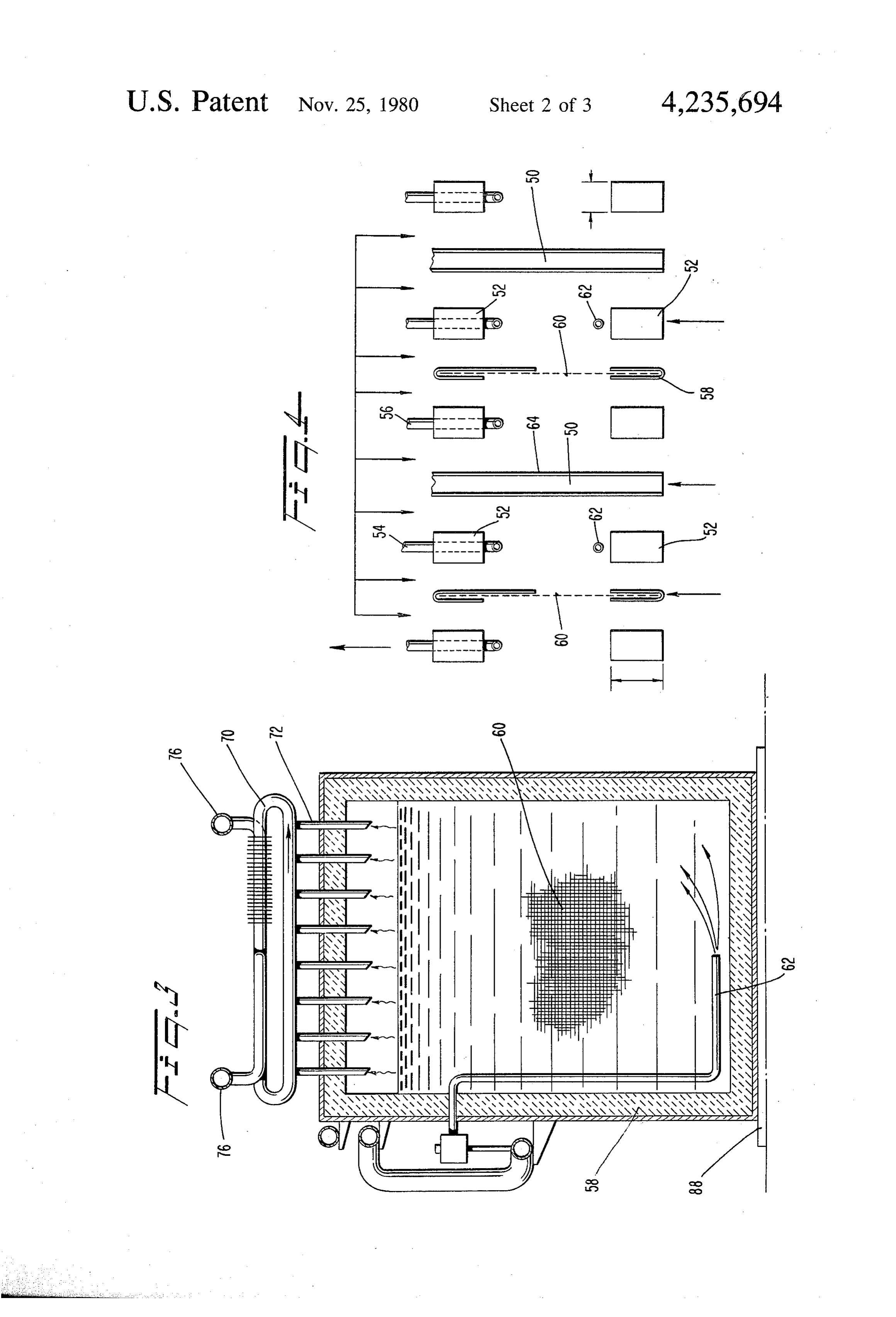
spaced between adjacent electrodes to divide each elec 10 Referring now to FIG. 4, each cell is comprised of trolytic cell chamber into two sections to prevent the electrodes 50, rectangular dielectric separator frames remixing of hydrogen and oxygen, alkaline electrolyte 52, a gas separator diaphragm 60, discrete off-gas pipes contained in each cell, means for introducing water to 54 and 56 arranged at the top of the cell, and makeup each of the electrolytic cell chambers, first manifold water inlets 62. The dielectric spearator frames 52 are means connected with like sections of each of said elec 15 disposed on opposite sides of a gas separator having a trolytic cell chambers for allowing off-gas withdrawal diaphragm fram 58 with a central opening containing of hydrogen, first automatic valve means for closing the gas separator diaphragm 60. Preferably, the elec said first manifold means whenever pressure within the trodes 50 of each cell are fused to the corresponding electrolytic cell chambers. is equal to or less than a dielectric separator frames 52 by a hot melt process preselected pressure, second manifold means connected 20 whereby the dielectric separator frame 52 is in turn with the other like sections of each electrolytic cell fused to the frame 58 of the gas separator. This fused chamber for allowing off-gas withdrawal of oxygen, construction provides a closed cell except for the off second automatic valve means for closing said second gas outlets and makeup water inlets. Electrolyte, of manifold means whenever pressure within the electro course, is disposed in each cell between the opposed lytic cell chambers is equal to or less than the prese 25 electrodes and communicates through the gas separator lected pressure and means for back-pressuring the exte diaphragm 60.
rior walls of each end plate electrode to counter-bal The electrolytic cell banks described hereinafter con ance any pressure developed within the adjacent elec sist of the following components:
trolytic cell chambers and exerted against the inside (1) Electrodes wall of the end plate electrodes. 30 (2) Dielectric Separators The accompanying drawings, which are incorpo (3) In-cell Gas Separation Diaphragms rated in and constitute a part of the Specification, illus (4) Electrolyte trate one embodiment of the invention and, together (5) Makeup Water Fill Valves with the description, serve to explain the principles of (6) Cell Off-gas Piping & Filters the invention. 35 (7) Cell-bank Off-gas Manifolds
BRIEF DESCRIPTION OF THE DRAWINGS
(8) Cathodic/Anodic End plates (9) Dielectric Skin
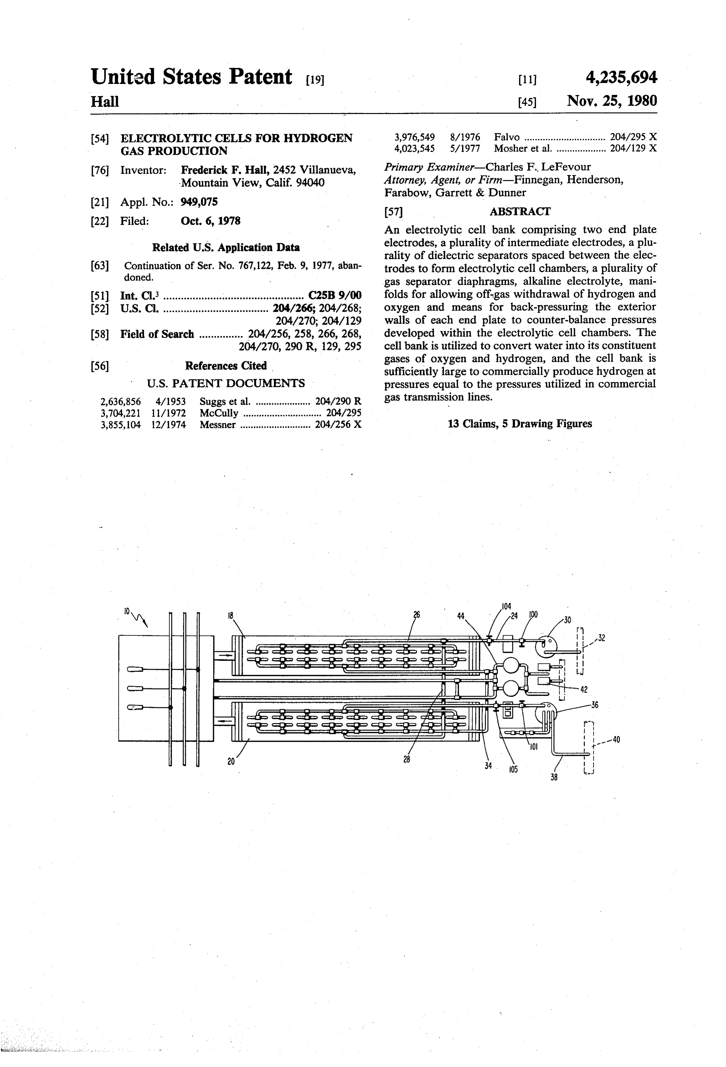
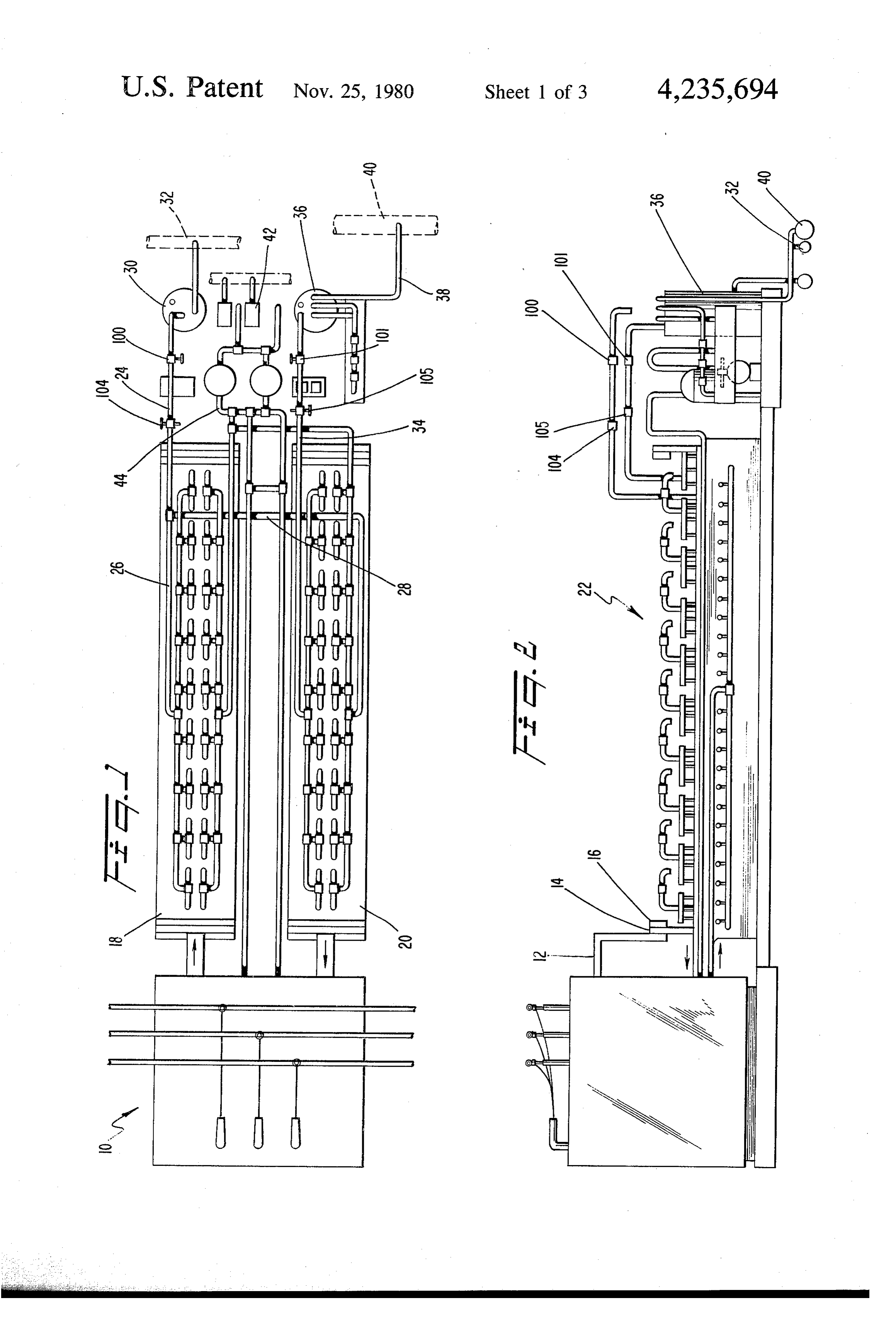
FIG. 1 is a plan view of a hydrogen production plant (10) Instrumentation & Control utilizing the electrolytic cell bank of the present inven The above listed electrolytic cell-bank components are tion; 40 described hereinbelow:
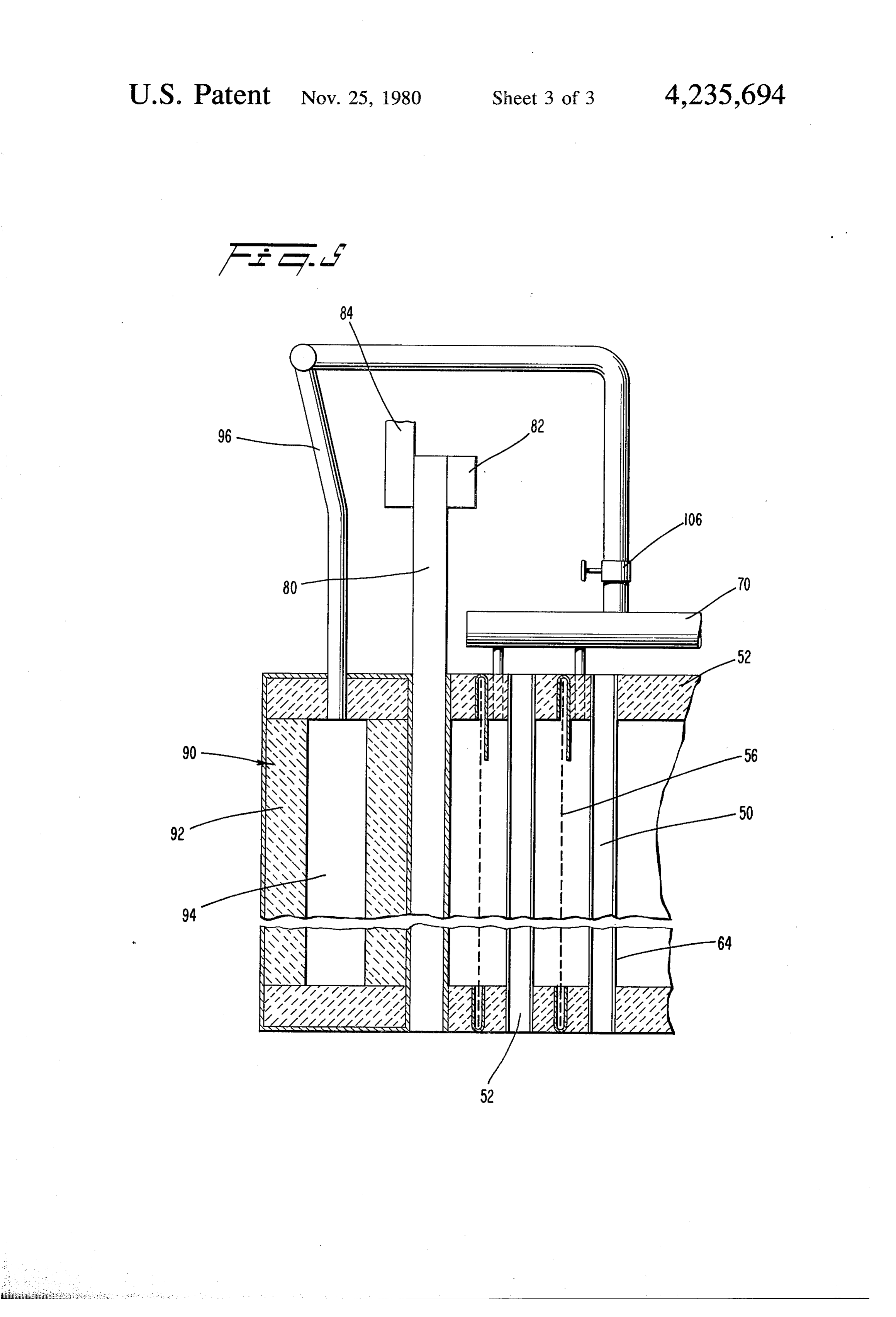
FIG. 2 is a side elevation view of the plant of FIG. 1; Electrode 50 are preferably bipolar to obviate the FIG. 3 is an enlarged cross-sectional view through need for expensive top-mounted DC current cell-to-cell one of the cells of the electrolytic cell bank illustrated in jumpers and are also thin to eliminate electrode IPR FIG. 1; FIG. 4 is a schematic side elevational view of losses as a major design consideration. Electrodes 50 are the elements comprising the cell banks in exploded 45 preferably laminated to allow low cost carbon steel juxtaposition relative to one another; and plate to be used as cores. The electrodes surfaces in FIG. 5 is an enlarged fragmentary cross-sectional contact with the electrolyte are clad with very thin view, taken perpendicular to the view shown in FIG. 4 sheets of austenitic stainless steel 64 to obviate electrode and with parts broken out for ease of illustration, of the corrosion and provide a surface for the evolution and construction of the end of the cell bank. 50 breakaway of gas bubbles. Very thin 304 L stainless
DESCRIPTION OF THE PREFERRED
steel electrical surface cladding would be satisfactory.
Electrodes 50 are built into cell-bank walls and act as
EMBODEMENT pressure-resisting diaphragms to allow in-cell pressures Reference will now be made in detail to the present to 1000 PSIA of higher so as to be above the operating preferred embodiment of the invention, an example of 55 pressure of existing fuel gas transmission piping systems. which is illustrated in the accompanying drawings. DC current can flow through electrodes 50 in either The hydrogen production plant utilizing the cell direction depending on the polarity of cell-bank end banks of this invention is illustrated in FIGS. 1 and 2 plates.
and comprises a power source generally designated 10, Dielectric separators 52 are formed using rectangular preferably and AC/DC rectifier, having suitable con 60 stock of thermoplastic material. The narrow dimension nections to a pair of cell banks 18 and 20 through a is sufficiently large to allow evolving bubbles to clear rectifier bus 12, an end plate 14, and a DC current equal surface of the electrolyte and leave through off-gas izing bar 16. Suitable off-gas piping, generally desig tubing 54, 56 at the top of cell. In effect the narrow nated 22, is connected to each of the cells to carry off dimension is equal to one-half of cell pitch. In the em generated oxygen and hydrogen. Particularly, the oxy- 65 bodiment shown in FIG. 5, the electrodes 50 are prefer gen off-gas flows through a conduit 24 in communica ably spaced one inch apart and the dielectric separators tion via branches 26 and 28 with each of the cell banks are 0.5' across. The dielectric separators 52 are wide for supply to a LOX cryostat 30. A LOX pipe 32 places enough to allow adherence to stainless steel surfaces
Page 7
and act as a beam to resist in-cell operating pressures. ods including occasional ganged refilling might be ade Preferably, dielectric separators 52 are formed of FEP quate. If individual valves were to be used the inner Teflon (fluorinated ethylene-propylene) and are ad workings would be similar to the low cost Fillmaster hered to the stainless steel surfaces of the electrodes 50 units used to replinish toilet bowl flushi tanks. The cost by the hot melt process at close to 1200' R. while under 5 of any system used will be pretty much the same and a compression pressure of at least 50 PSIG. Other suit cost will not be a major consideration. A glass rod peep able material or assembly procedure could be utilized. hole is also provided through the FEP Teflon tank sides FEP Teflon also is one of the few plastics which can be before the hot melt process, as necessary to allow visual used continously at temperatures of 800 R. or slightly checking of in-cell conditions and fill valve adjustment. higher without loss of strength. 10 It is important to keep the electrolyte solution the Each cell is divided into two sections by the gas same from cell to cell and at the optimum strength of separation diaphragm 60 to prevent remixing of hydro 15% for NaOH or 25% for KOH to maximize cell-bank gen and oxygen bubbles. Diaphragms of woven asbes performance. For reasons discussed later, cell width is tos fiber have almost universally been used despite preferably about nine feet. Each half of each cell is strong evidence of steady deterioration in service. It is 15 provided with a manifold 70 (FIG. 3) with a number of not possible to design electrolytic cells that are low in beveled tee connections 72. These manifolds in the cost if any of the internals must be inspected and main preferred embodiment, are eight feet long to allow off tained or replaced from time to time. In the preferred gas withdrawal equally across the cell width at one-foot embodiment gas separation diaphragms are preferably centers. The flow area of eight beveled tees is sufficient made up using two layers of fabric 60 having a fine 20 to maintain velocity of hydrogen gas leaving a cell at weave using glass fiber yarns. Glass cloth does not 100 feet per minute or less to minimize carryover of deteriorate when immersed for long periods in strong liquid spatters. Manifold 70 are at staggered levels to alkaline electrolyte solutions nor will its weave inhibit permit the nominal diameter of the manifold to be pref rapid passage of ions toward oppositely charged elec erably one-half of an inch. Manifolds would be filled trode surfaces. Glass cloth 60 is preferably crimped into 25 with compressed glass wool to offer substantial surface frames 58 made up of FEP Teflon sheeting to prevent area for plating out of liquids which can then drain back the glass yarns from reaching cell-bank tank wall sur to the cell through any of the eight tee connections 72. faces and acting as weep paths which could results in The ends of manifolds 70 are U-bent to form a second loss of electrolyte. Use of FEP Teflon insures proper manifold with a single tee connection aimed up near the self-welding into tank walls during the hot melt process 30 centerline of cell. These second manifolds are finned, needed to adhere the FEP Teflon dielectric separator filled with compressed glass wool and cambered to stock 52 to the stainless steel surfaces 64 of electrodes allow any added liquid that passes through the first 50. Frames 58 minimize distortion and insure proper manifold trap to condense, plate out and drain outward areas for rising gas bubbles. FEP Teflon sheeting is also and downward to one of the first level manifolds. The used in the gas phase portion of the cells above the 35 upward aimed tees of the second level manifold are electrolyte surface to create a solid gas separation bar extended to cell-bank off-gas manifolds 76. It is ex re. pected that the filtering capability of the cell off-gas If sea water could be used functionally as the electro piping as described above will approach that of lyte its cost would be very low. However a salt water 99.999998% effective microalescent type oil separators solution with the same strength as sea water will very 40 as are often used in air compressor discharge piping. All quickly attack stainless steel and visibly contaminate the piping described above is preferably formed of stainless electrolyte. Acid solutions hold no advantages and steel tubing. Beveled tees are welded to the manifolds. would increase corrosion problems. Accordingly, an All manifold connections are preferably effected using alkaline electrolyte is used in the present invention. highest grade compression fittings. Either a 15% solution of NaOH or a 25% solution of 45 Every other half cell top level manifold has its up KOH could be used. KOH costs close to 50% more ward aimed tee connected to one of two cell-bank off than NaOH but has less electrical resistance than NaOH gas manifolds 76. All remaining upward aimed tees are at all operating temperatures of interest. The recom connected to a second cell-bank off-gas manifold. Cell mended alkaline electrolyte therefore is KOH despite bank off-gas manifolds are preferably all-welded, seam the 250% increase in cost. Since the initial charge of 50 less 304L austenitic stainless steel and have pulled tees electrolyte will be used throughout the life of an elec for connection to cell off-gas outlets. Connections be trolytic cell bank, the initial extra electrolyte cost is no tween cell off-gas outlets and cell-bank off-gas mani substantial economic problem. folds preferably have a minimum of one right angle Each cell also receives makeup water to replace bend and cell-bank manifold pulled tees aim down. water that is disassociated. The system used to supply 55 Each cell-bank off-gas manifold outlet has an automatic makeup water must be dielectric in nature in order to valve (100 and 101) actuated to close whenever in-cell maintain effective cell-bank operation. Plastic piping 44 pressure is equal to or less than extraneous gas main (FIG. 1) can be used and the water is easily demineral pressure. Cell-bank manifolds are located downstream ized to a specific resistance of two ohms. Makeup water of safety valves 104 and 105 set some 50 PSIA above the pressure must exceed in-cell pressure and this is pro 60 highest anticipated in-cell working pressure and sized to vided by canning inexpensive low differential pressure prevent bursting of cell-banks. Each cell-bank off-gas type fill valves within high pressure rated valve bodies. manifold preferably has a three-quarter inch valved The problem can be compounded if cell-banks are oper outlet 106 close to each cathodic/anodic end plate for ated at widely fluctuating load levels since electrolyte back-pressuring end plates as will be discussed in the density will be least when operation is at high. tempera 65 next section. Each end of each cell-bank off-gas mani ture and higher than normal rates of hydrogen produc fold is also preferably provided with a means of deter tion. Preferably therefore individual fill valves are pro mining whether the respective manifold contains hy vided for each cell. It is not precluded that other meth drogen or oxygen so that operators will know for cer
Page 8
tain which manifold contains fuel gas and which does to any practical length keeping in mind that heated Ot. rooms for successful use of the hot melt process must Cell bank cathodic/anodic end plates 80 are similar toalways be larger than the cell-banks units assembled. electrodes 50 except that carbon steel for example on Since ratio of cell-bank weight to cell-bank volume is the order of one-inch thick are provided to reduce IR 5 low, long units can be readily loaded and unloaded. The losses to a minimal level and equalize distribution of dimensions suggested herein are reasonable maxima in arriving or leaving DC current. End plates 80 are clad view of standard truck and flat car dimensions. with very thin sheets of austenitic stainless steel to pre What is claimed is:
went corrosion. The end plates 80 extend above the 1. A bank of electrolytic cell for electrolytically con cell-bank tank and have a top-mounted copper bar 82 10 verting water into its constituent gases of hydrogen and for equalizing DC current across the top of plates. End oxygen upon the application of a voltage source com plate extensions are also provided with bolt-holes for prising:
attaching DC bus bars to or from DC recitifers. Each two end plate electrodes, end plate preferably has its outer surface lined with thin a plurality of intermediate electrodes spaced between strips of electrode material 90 alternated around FEP 15 said end plate electrodes,
Teflon stock 92 to create a series of one-inch square a plurality of dielectric separators individually spac pressure pockets running from top to bottom of the end ing and electrically separating adjacent electrodes plate and dead ended at top and bottom of the end plates from one another and together with the said elec except for a topmounted stainless steel back-pressure trodes forming impervious electrolytic cell cham manifold 96 within the order of 105 tees penetrating the bers between adjacent electrodes, pressure devel FEP Teflon top plate. This assembly is adhered to itself oping in said chamber during the converting of and to end plates 80 during the hot melt procedure used water into hydrogen and oxygen, to weld the rest of the cell-bank into a sealed pressure a plurality of gas separator diaphragms individually tank. The back pressure manifold has two valved tees spaced between adjacent electrodes to divide each aimed upward. These tees are connected to the cell 25 said electrolytic cell chamber into two sections to bank manifold valved tees, discussed previously by prevent the remixing of hydrogen and oxygen, using removable sections of stainless steel pipe. When alkaline electrolyte contained in each cell chamber, the cell banks are about to be put into operation the means for connecting a voltage source to said elec cell-bank oxygen manifold connection valves are trodes, locked open and the hydrogen manifold connection means for introducing water to each of said electro valves are closed and the connecting pipes are removed. lytic cell chambers,
When a cell-bank is completely assembled and prefer first manifold means connected with like sections of ably hot melt sealed, it is leak checked and any leaks each of said electrolytic cell chambers for allowing sealed by local heat welding procedures. Next the cell off-gas withdrawal of hydrogen, bank is sure tested at one-and-one half times its design 35 first automatic valve means for closing said first mani maximum working pressure. A one-inch thick PVC sole fold whenever the pressure within said electrolytic 88 (FIG. 3) is laid out using small sheets pretreated with cell chambers is equal to or less than a preselected a weather resistant, pressure sensitive adhesive. Joints pressure, are left open and poured full of an adhesive that will second manifold means connected with the other like adhere to PWC but not to floor. The cell-bank is then 40 lowered onto its PVC sole which will act as a perma sections of each electrolytic cell chambers for al ment dielectric barrier anl a semi-adjustable bed plate to lowing off-gas withdrawal of oxygen, allow placement of the cell-banks on pavement in lieu of second automatic valve means for closing said Second special an expensive bases. Likewise sides and ends of manifold means whenever pressure within said cell-banks are faced with one-eighth inch thick sheets of 45 electrolytic cell chambers is equal to or less than PVC pretreated with a weather resistant, pressure sensi preselected pressure, tive adhesive. Joints are left open and filled with means for back-pressuring the exterior walls of each weather resistant adhesive. These sheets act as a perma end plate electrode to counter-balance any pressure ment dielectric barrier and ultra violet light filter. Fi developed within the adjacent electrolytic cell nally, the top of the cell-bank is mopped with an one SO chambers and exerted against the inside wall of the eighth inch thick epoxy cement or equal to serve the end plate electrodes.
same purpose as the side and end sheeting. The dielec 2. The modular bank of claim 1 wherein said interme tric skin of the cell-banks also protects exposed carbon diate electrodes are clad with a thin sheet of stainless steel core of the electrodes and end plates against rust steel to obviate electrode corrosion and provide a sur ing for decades and longer. Cell-bank corners are pro 55 face for the evolution and break away of gas bubbles tected against physical damage by adding corner angles and wherein said dialectric separators are formed of pretreated with pressure sensitive weather resistant fluorinated ethylene-propylene.
adhesive. 3. The modular bank of claim 1 wherein said dialec Little or no instrumentation and control would be tric separators are adhered to said stainless steel elec required to operate the present invention. Those that 60 trode surfaces by a hot-melt process practiced at a tem would be useful will already be available at DC rectifier perature greater than 1000 R. and at a pressure greater control panel or at a control panel located within a than 25 psi.g. - mechanical equipment bay. 4. The modular bank of claim 1 wherein said gas By using nine feet wide by ten feet high by up to 70 separator diaphragm is formed of two layers of finely feet long or even longer cells, the cells allow units of 65 woven glass fabric which permits the free migration of significant hydrogen production capacity to be readily electrolyte through said diaphragm.
shipped by truck, rail, plane or container cargo ships. 5. The modular bank of claim wherein said electro Since the cell-banks are modular they can be assembled lyte is 15% NAOH.
Page 9
6. The modular bank of claim 1 wherein said electro withstanding pressures equal to or greater than the lyte comprises 25% KOH. gas transmission pressure, 7. The modular bank of claim 1 wherein said first a plurality of gas separator diaphragms individually manifold means includes a manifold filled with com spaced between adjacent electrodes to divide each pressed glass wool to offer a surface area for plating out said electrolytic cell chamber into two sections to of liquids carried by off-gas. prevent the remixing of hydrogen and oxygen, 8. The modular bank of claim 1 wherein said back alkaline electrolyte contained in each cell chamber, pressuring means comprises a material adhered to the means for connecting a voltage source to said elec exterior wall of each end plate to form pressure pockets 10 trodes, and back-pressure manifold connected to said pressure means for introducing water to each of said electro pockets. lytic cell chambers, first manifold means connected with like sections of 9. The modular bank of claim 8 wherein said back each of said electrolytic cell chambers for allowing pressure manifold is connected with said second mani off-gas withdrawal of hydrogen, fold means. 15 first automatic valve means for closing said first mani 10. The modular bank of claim 1 wherein said con fold means whenever pressure within said electro necting means comprise extensions of said end plate lytic cell chambers is equal to or less than the electrodes for connection to DC power bus bars. working pressure of the gas transmission line, 11. The modular bank of claim 1 wherein said bank second manifold means connected with the other like includes means for permitting operation attemperatures 20 sections of each electrolytic cell chamber for al up to 810 R. and pressures up to 1000 psig, lowing off-gas withdrawal of oxygen, 12. A bank of electrolytic cells for electrolytically second automatic valve means for closing said second converting water into its constituent gases of hydrogen manifold means whenever the pressure within said and oxygen upon the application of a voltage source electrolytic cell chambers is equal to or less than and for producing hydrogen at a pressure equal to or 25 the working pressure of the gas transmission line, greater than the working pressure of a gas transmission and line comprising: means for back-pressuring the exterior walls of each two end plate electrodes, end plate electrode to counter-balance pressure a plurality of intermediate, bipolar planar electrodes developed within said electrolytic cell chambers spaced between said end plate electrodes, said in 30 and exerted against the inside wall of the end plate termediate electrodes being clad with a thin sheet electrodes.
of stainless steel to obviate electrode corrosion and 13. The modular bank of claim 12 wherein said di provide a surface for the evolution and break-away electric separators are formed of fluorinated ethylene of gas bubbles, propylene and are adhered to said stainless steel elec a plurality of dielectric separators spacing and electri 35 trode surfaces by a hot-melt process practiced at a tem cally separating adjacent electrodes from one an perature greater than 1000 R. and at a pressure greater other and together with said electrodes forming than 25 psig. sk :k it k k impervious electrolytic cell chambers capable of

Provenance
- Collection
- Cited prior art
- Original PDF
- patentimages.storage.googleapis.com →
- Filed
- 1978-10-06
- Pages
- 9
- Method
- pdftotext (the PDF's own text layer) + pdftoppm 300dpi page scans
- Source
- Google Patents bibliographic record
- Granted
- 1980-11-25
- Inventors
- Frederick F. Hall
- Transcribed from
- patentimages.storage.googleapis.com →