patent · US4256554
Electrolytic cell for separating chlorine gas from other gases
17 March 1981
Page 1 — bibliographic record
United States Patent (19) (11) 4,256,554 Bjorkman, Jr. (45) Mar. 17, 1981 (54) ELECTROLYTIC CELL FOR SEPARATING 4,217,401 8/1980 Pellegri................................ 204/266 CHLORINE GAS FROM OTHER GASES Primary Examiner-T. M. Tufariello 75) Inventor: Harry K. Bjorkman, Jr., Attorney, Agent, or Firm-Harness, Dickey & Pierce Birmingham, Mich. 57 ABSTRACT 73) Assignee: Energy Development Associates, Inc. An electrolytic cell for separating chlorine gas from Madison Heights, Mich. other (foreign) gases, having an anode electrode, a cath 21 Appl. No.: 134,929 ode electrode, a gas impermeable (but liquid permeable) 22 Filled: Mar. 28, 1980 membrane interposed between the anode and cathode (22) Filed: ar. Zs, electrodes, an aqueous electrolyte, a housing, and a 51) Int. Cl. ........................... C25B 1/26; C25B 9/00 constant voltage power supply. The electrolytic cell (52) U.S. C. .................................... 204/128; 204/258; may be constructed in either a rectangular or cylindri 204/260; 204/265; 204/266 cal geometry, and may be combined with other electro 58 Field of Search ............... 204/128, 130, 258, 260, lytic cells to form a multiple cell system. In operation, a 204/266, 278, 265 stream of chlorine and foreign gases enters the cell at (56) References Cited the lower portion of the cathode electrode. The chlo rine gas is dissolved into the electrolytic and electro
3,813,301 5/1974 Carr ....................................... 429/50 ions diffuse through the gas impermeable membrane, 3,841,989 10/1974 Delsa ....... - - - 5,5. and are electrochemically oxidized at the anode into E; Ag: Mer a m 3.2 purified chlorine gas. The foreign gases do not partici 3569258 5/1975 car. . 97 pate in the above, and are vented from the cell. 3,954,502 5/1976 Symons .................................. 429/39 4,77,116 12/1979 Denora ................................. 204/260 21 Claims, 6 Drawing Figures
Page 2
Drawing sheet — no readable text.
Page 3
Drawing sheet — no readable text.
Page 4
The present invention further provides for a novel
ELECTROLYTIC CELL FOR SEPARATING multiple cell system for use when the gas flow rate into CHLORINE GAS FROM OTHER GASES one cell is beyond its capacity to reduce all of the chlo rine gas entering the cell. Generally, when the chlorine
BACKGROUND AND SUMMARY OF THE 5 and foreign gas flow rate into a cell is very low, even an
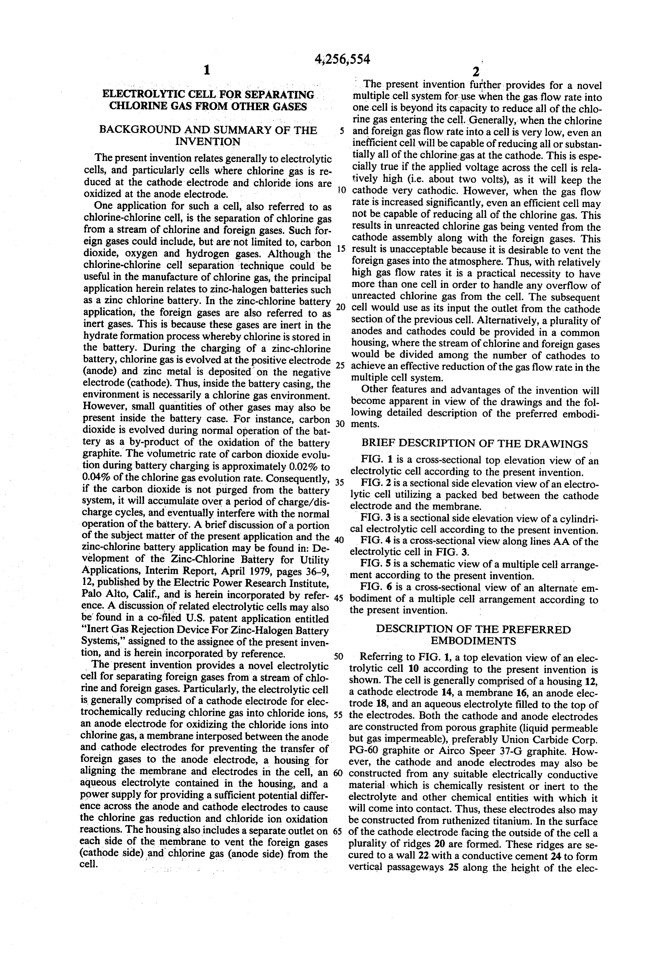
INVENTION inefficient cell will be capable of reducing all or substan The present invention relates generally to electrolytic tially all of the chlorine gas at the cathode. This is espe cells, and particularly cells where chlorine gas is re cially true if the applied voltage across the cell is rela duced at the cathode electrode and chloride ions are tively high (i.e. about two volts), as it will keep the oxidized at the anode electrode. O cathode very cathodic. However, when the gas flow One application for such a cell, also referred to as rate is increased significantly, even an efficient cell may chlorine-chlorine cell, is the separation of chlorine gas not be capable of reducing all of the chlorine gas. This from a stream of chlorine and foreign gases. Such for results inassembly unreacted chlorine gas being vented from the eign gases could include, but are not limited to, carbon 15 cathode result is along with the foreign gases. This unacceptable because it is desirable to vent the dioxide, oxygen and hydrogen gases. Although the chlorine-chlorine cell separation technique could be high foreign gases into the atmosphere. Thus, with relatively useful in the manufacture of chlorine gas, the principal more gas flow rates it is a practical necessity to have than one cell in order to handle any overflow of application herein relates to zinc-halogen batteries such unreacted chlorine gas from the cell. The subsequent as a zinc chlorine battery. In the zinc-chlorine battery 20 application, the foreign gases are also referred to as sectioncell would use as its input the outlet from the cathode inert gases. This is because these gases are inert in the anodes of the previous cell. Alternatively, a plurality of and cathodes could be provided in a common hydrate formation process whereby chlorine is stored in housing, the battery. During the charging of a zinc-chlorine would bewhere the stream of chlorine and foreign gases divided among the number of cathodes to battery, chlorine gas is evolved at the positive electrode 25 achieve (anode) and zinc metal is deposited on the negative multipleancelleffective system.
reduction of the gas flow rate in the electrode (cathode). Thus, inside the battery casing, the Other features and advantages of the invention will environment is necessarily a chlorine gas environment. become apparent in view of the drawings and the fol However, small quantities of other gases may also be lowing detailed description of the preferred embodi present inside the battery case. For instance, carbon 30 ments.
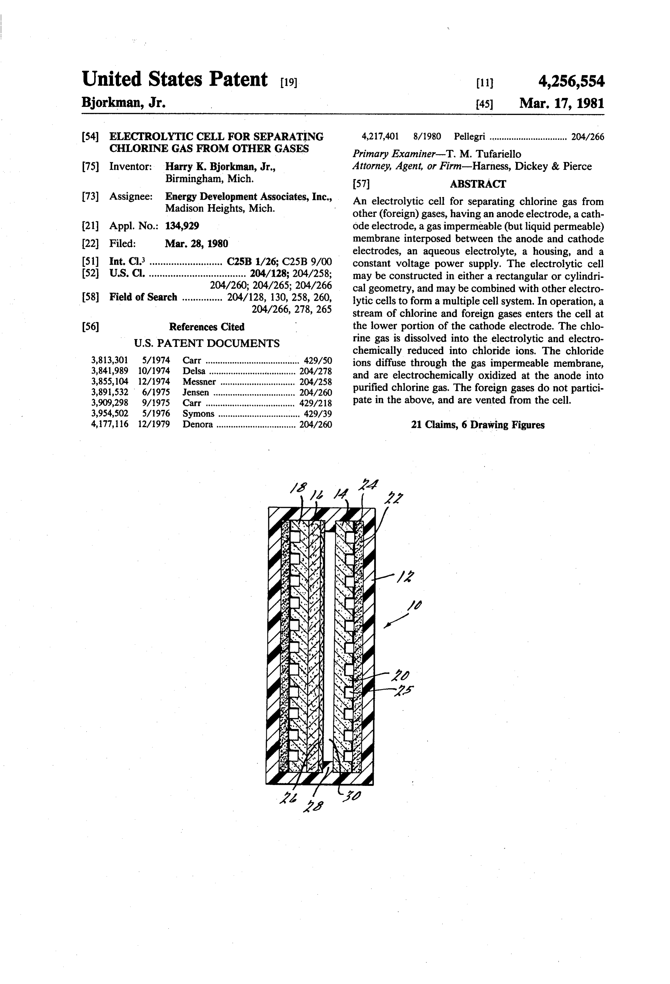
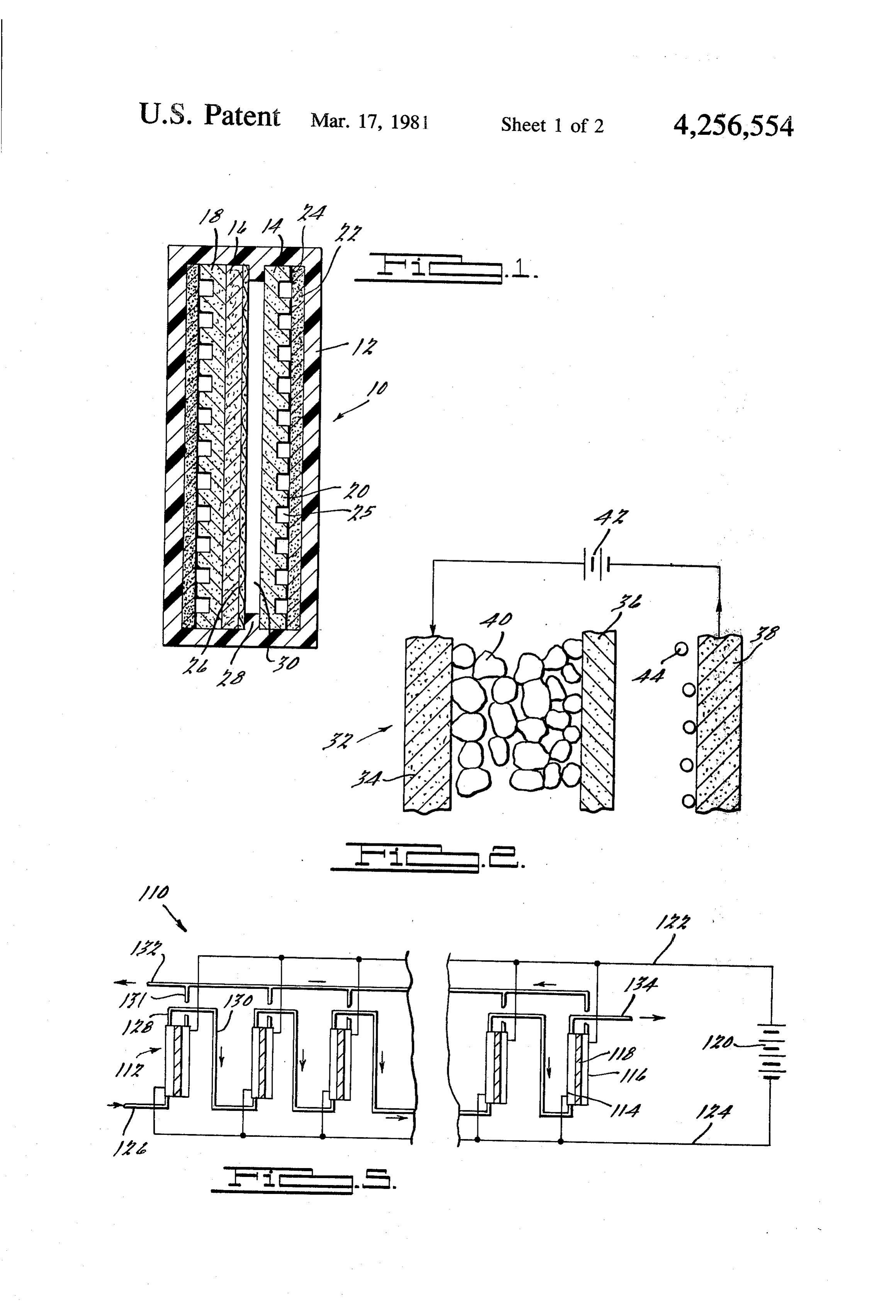
dioxide is evolved during normal operation of the bat tery as a by-product of the oxidation of the battery BRIEF DESCRIPTION OF THE DRAWINGS graphite. The volumetric rate of carbon dioxide evolu FIG. 1 is a cross-sectional top elevation view of an tion during battery charging is approximately 0.02% to electrolytic 0.04% of the chlorine gas evolution rate. Consequently, 35 FIG. 2 is acell according to the present invention. sectional side elevation view of an electro if the carbon dioxide is not purged from the battery lytic cell utilizing a packed bed between the cathode system, it will accumulate over a period of charge/dis electrode and the membrane.
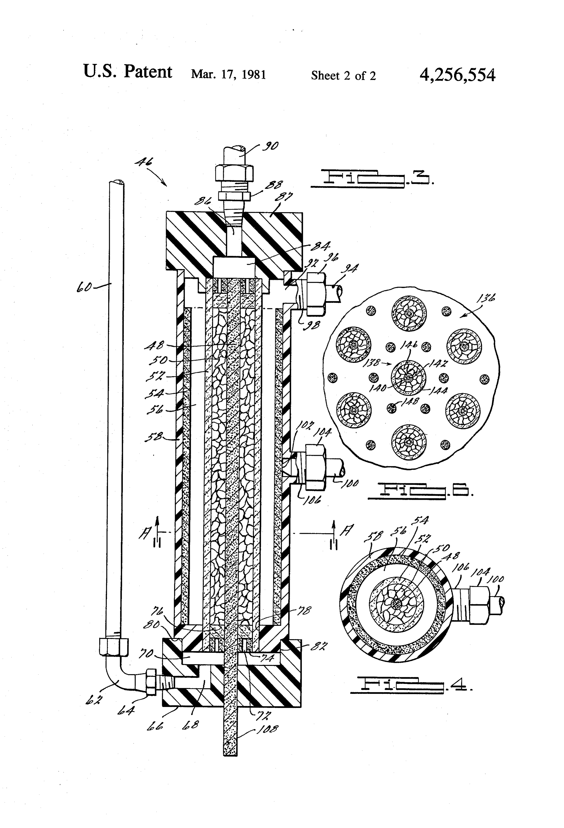
charge cycles, and eventually interfere with the normal FIG. 3 is a sectional side elevation view of a cylindri operation of the battery. A brief discussion of a portion cal electrolytic cell according to the present invention. of the subject matter of the present application and the FIG. 4 is a cross-sectional view along lines AA of the zinc-chlorine battery application may be found in: De electrolytic cell in FIG. 3.
velopment of the Zinc-Chlorine Battery for Utility FIG. 5 is a schematic view of a multiple cell arrange Applications, Interim Report, April 1979, pages 36-9, ment according to the present invention. 12, published by the Electric Power Research Institute, FIG. 6 is a cross-sectional view of an alternate em Palo Alto, Calif., and is herein incorporated by refer 45 bodiment of a multiple cell arrangement according to ence. A discussion of related electrolytic cells may also the present invention.
be found in a co-filed U.S. patent application entitled
"Inert Gas Rejection Device For Zinc-Halogen Battery DESCRIPTION OF THE PREFERRED Systems," assigned to the assignee of the present inven EMBODIMENTS tion, and is herein incorporated by reference. 50 Referring to FIG. 1, a top elevation view of an elec The present invention provides a novel electrolytic trolytic cell 10 according to the present invention is cell for separating foreign gases from a stream of chlo shown. The cell is generally comprised of a housing 12, rine and foreign gases. Particularly, the electrolytic cell a cathode electrode 14, a membrane 16, an anode elec is generally comprised of a cathode electrode for elec trode 18, and an aqueous electrolyte filled to the top of trochemically reducing chlorine gas into chloride ions, 55 the electrodes. Both the cathode and anode electrodes an anode electrode for oxidizing the chloride ions into are constructed from porous graphite (liquid permeable chlorine gas, a membrane interposed between the anode but gas impermeable), preferably Union Carbide Corp. and cathode electrodes for preventing the transfer of PG-60 graphite or Airco Speer 37-G graphite. How foreign gases to the anode electrode, a housing for ever, the cathode and anode electrodes may also be aligning the membrane and electrodes in the cell, an 60 constructed from any suitable electrically conductive aqueous electrolyte contained in the housing, and a material which is chemically resistent or inert to the power supply for providing a sufficient potential differ electrolyte and other chemical entities with which it ence across the anode and cathode electrodes to cause will come into contact. Thus, these electrodes also may the chlorine gas reduction and chloride ion oxidation be constructed from ruthenized titanium. In the surface reactions. The housing also includes a separate outlet on 65 of the cathode electrode facing the outside of the cell a each side of the membrane to vent the foreign gases plurality of ridges 20 are formed. These ridges are se (cathode cell.
side) and chlorine gas (anode side) from the cured to a wall 22, with a conductive cement 24 to form vertical passageways 25 along the height of the elec
Page 5
trode. Wall 22 is constructed from dense or fine grained appropriate aperture in the top of the housing. The graphite (liquid and gas impermeable), preferably chloride ions in the cell gap 30 diffuse through mem Union Carbide Corp. CS grade graphite. The cement is brane 16, and are electrochemically oxidized at anode an electrically conductive resinous polymeric cement, electrode 18 to form chlorine gas. Although in practice such as Cotronics Corp. 93 graphite adhesive or a 5 a portion of the chlorine gas was generated in the pas composition of graphite and furfuryl alcohol. As illus sageways of the anode electrode, most of the chlorine trated in FIG. 1, a similar construction for the formation gas was generated at the surface of the anode electrode of passageways is provided for anode electrode 8. A facing the membrane. As a result, the chlorine gas gen more detailed description of the electrode and passage erated at this interface was forced to push the mem ways may be found in U.S. Pat. No. 3,954,502 issued O brane aside in order to rise up the electrode and be May 4, 1976, entitled "Bipolar Electrode For Cell Of vented out of the cell. Although this result was undesir High Energy Density Secondary Battery,” and is herein able, this cell successfully demonstrated the concept of incorporated by reference. separating foreign gases from a stream of chlorine and Interposed between cathode electrode 14 and anode foreign gases through the use of an electrolytic cell. electrode 18 is membrane 16. The membrane may be 15 In order for the reduction of chlorine gas and oxida made from any suitable material which will permit the tion of chloride ions to take place, a sufficient potential transfer of ions and liquid and prevent the transfer of difference must be provided between the cathode and gas across it, and be chemically resistent or inert to the anode electrodes. Such potential difference may be in electrolyte and other chemical entities with which it the range of 0.2 to 2.0 volts. Any suitable direct current will come into contact. Thus, the membrane may be 20 (constant voltage) power supply may be used which constructed from asbestos, ceramics, Dupont Nafion, or will provide an appropriate current density over the porous graphite. In the electrolytic cell of FIG. 1, an active surface area of the cell in the above-identified asbestos membrane is employed. This membrane is held voltage range. Such a power supply should be capable in place by a titanium mesh screen 26, and the screen is of providing a current density up to 300 milli-amperes in turn held in place by a spacer member 28 on each side 25 per square centi-meter of active (apparent) surface area. of the cell. It should be appreciated that if another mate Referring to FIG.2, a sectional side elevation view of rial is used for the membrane in substitution for the an electrolytic cell 52 illustrating the concept of a cath asbestos, such as porous graphite, the titanium mesh ode assembly if shown. The cathode assembly is gener screen is not necessary and may be deleted. With such a ally comprised of a cathode electrode 34, a membrane substitution, the spacers also provide an electrical isola 30 36, and a packed bed of graphite particles 40 interposed tion between the cathode and anode electrodes in the between the cathode electrode and the membrane. Both cell, as exemplified by cell gap 30. The spacers are the cathode electrode 34 and the anode electrode 38 are preferably constructed from the same material as hous constructed from dense or fined grained graphite. The ing 12, and may be an integral part thereof. The housing graphite particles (or powder) provide the primary sites may be made from any suitable electrically non-conduc 35 for the reduction of chlorine gas, and provide a substan tive material, which is chemically resistent or inert to tial increase in the available surface area for the chlorine the electrolyte and other chemical entities with which it gas reduction to take place. The graphite powder is will come into contact. Thus, the housing may be con made from activated Union Carbide Corp. PG-60 structed from such materials as General Tire & Rubber graphite. A description of the preferred process for Corp. Boltron polyvinyl chloride (4008-2124), Dupont activating graphite may be found in U.S. Pat. No. Teflon (tetrafluorinated ethylene), Pennwalt Kynar 4,120,774, issued Oct. 17, 1978, entitled "Reduction of (polyvinylidene fluoride), or any of the other appropri Electrode Overvoltage," and is herein incorporated by ate materials described in Section 33 of the Develop reference. However, it should be understood that other ment of the Zinc-Chlorine Battery for Utility Applica electrically conductive, electrochemically active, and tions report identified earlier. 45 chemically resistive or inert materials may be employed The electrolyte for this cell (as well as for the subse as a substitute for the graphite powder, such as particles quent embodiments) is preferably composed of a 10% of carbon or ruthenized titanium.
by weight solution by hydrochloric acid in water. How Also shown in FIG. 2 is a schematic representation of ever, the hydrochloric acid concentration may be var a source of direct current electrical powder, and direc ied over a range from 5% to 30% without an apprecia 50 tion of the current flow as indicated by the arrows. ble affect on the performance of the cell. Alternate Finally, for illustrative purposes gas bubbles 44 are chloride ion containing electrolytes may also be pro shown, and represent the chlorine gas generated at the vided, such as zinc chloride, potassium chloride or so anode electrode.
dium chloride. Referring to FIG. 3, a sectional side elevation view of In operation, the stream of chlorine and foreign gases 55 a cylindrical cell 46 according to the present invention enters cell 10 at the bottom of passageways 25. The is shown. This cell represents the embodiment of the chlorine gas dissolves into the electrolyte and diffuses cathode assembly concept illustrated in FIG. 2. Cell 46 through cathode electrode 14, where it is electrochemi is generally comprised of a cathode electrode rod 48, a cally reduced into chloride ions. However, as the for packing of graphite particles 50, a membrane cylinder eign gases do not dissolve into the electrolyte or partici 60 52, an anode electrode cylinder 54 suitably larger in pate in any electrochemical reactions, they will rise up diameter than the membrane to provide for cell gap 56, the passageways and be vented into cell gap 30 through and a housing 58. A cross-sectional view of this cell is holes (not shown) drilled in the cathode electrode at the also shown in FIG.4, which is taken along lines AA of top of the passageways. Any unreacted and undissolved FIG. 3. In this embodiment, the cathode electrode rod chlorine gas will also be vented along with the foreign 65 and anode electrode cylinder are constructed from gases. As membrane 16 is gas impermeable, the foreign dense or fine grained graphite, the membrane is con and chlorine gases are prevented from reaching anode structed from porous graphite and the housing is con electrode 18, and are vented from the cell through an structed from Boltron polyvinyl chloride.
Page 6
The stream of chlorine and foreign gases is injected dent from the flow rate of the gases and the efficiency of into the cell through tube 60, which is preferably con the cells, The chlorine gas generated at the anode elec structed from Teflon. The gases travel through tube 60, trode in the first cell is vented through outlet tube 131 elbow 62, connector 64, and enter the cell through and into tube 132, which collects the chlorine gas gener. passageways 68 and 70 provided in the bottom cap 66 of ated in each of the cells. Finally, tube 134 from the the housing. The gases then travel through the plurality cathode section of the last cell provides the outlet for of holes 72 in the dense graphite plug 74, diffuse the foreign gases from the cell arrangement (which may through a layer of Carborundum Co. graphite felt 76, be simply vented into the atmosphere). and enter the packed bed of graphite particles 50. It Referring to FIG. 6, a cross-sectional view of an should be appreciated that a gas-tight seal is achieved at 10 alternate embodiment of a multiple cell arrangement the bottom of membrane 52 in order to prevent the 136 according to the present invention is shown. In this foreign gases from entering cell gap 56. This seal is cell design, a plurality of cathode assemblies 138 and achieved by a press fit between plug 74 and one face of anode electrodes 148 would be contained in a common membrane 52, and a press fit between the other face of housing (not shown). As in the cell design of FIG. 3, the the membrane and surface 78 of the housing. Surface 78 15 cathode assembly employs a dense graphite cathode may additionally be supplied with a coating of a Kynar electrode rod 140, a porous graphite membrane cylinder adhesive (75% NN-dimethyl formamide) in order to 144, and a packing of graphite particles 146. However, cement the housing to the membrane. This Kynar adhe an alternate means for injecting the stream of chlorine sive may also be used to seal bottom cap 66 to the hous and foreign gases into the cathode assembly is illus ing at surfaces 80 and 82, or in addition or as a substitu 20 trated. By providing a hole 142 through the length of tion, plastic welding techniques may be used as well. It the cathode electrode rod (and a cross hole in the rod at should be observed that a similar plug, felt, and sealing the bottom of the graphite packing), the gases could be construction is also employed at the top of the cell. injected down through the center of the cathode assem The foreign gases and any unreacted chlorine gas is bly. It should be appreciated that a Teflon tube could be vented from the top of the cathode assembly into pas 25 used in the place of the cathode electrode rod. In such sageways 84 and 86 in the top cap 87 of the housing. a case, at least one of the dense graphite plugs sealing These gases are then vented from the cell through con the top and bottom of the cathode assembly (corre nector 88 and tube 90. As with tube 60, tube 90 is also sponding to plug 74 of FIG. 3) would be incorporated preferably made from Teflon. Connectors 64 and 88, as into a dense graphite bus structure connecting each of well as elbow 62, are preferably made from Kynar. 30 the cathode assemblies in the cell arrangement. In either The chlorine gas generated at anode electrode 54 case, a dense graphite bus structure would also be pro rises up into the gas space 92 above the electrolyte type vided to connect each of the anode electrode rods 148. (at the top of the anode electrode), and is vented out of Thus, these bus structures would provide an electrically the cell through tube 94. Tube 94 is preferably made parallel connection for the respective cathode assem from Teflon, and is secured to the housing by a Kynar 35 blies and anode electrodes in the cell arrangement. It threaded cap 96 over housing portion 98. A similar should also be appreciated that the cell arrangement in construction is also employed to provide an electrical FIG. 6 would not employ the successive passes of the connection from the power supply to the anode elec foreign and unreacted chlorine gases from one cell to trode. A dense graphite rod 100 is inserted into the another, as in the cell arrangement of FIG. 5. Rather, housing, and is pressed up against surface 102 of the the stream of chlorine and foreign gases entering the anode electrode to provide this electrical connection. cell arrangement would be divided among the plurality Rod 100 is secured to the housing by threaded cap 104 of cathode assemblies 138. Thus, a complete separation over housing portion 106. The electrical connection for of the foreign gases from the chlorine gas would be the cathode electrode may be made by conventional achieved by dividing the flow rate of the stream of means anywhere along portion 108 of the cathode elec 45 gases among the number of cathode assemblies in the trode rod. cell arrangement.
Referring to FIG. 5, a schematic view of a multiple It will be appreciated by those skilled in the art that cell arrangement 110 according to the present invention various changes and modifications may be made to the is shown. The plurality of electrolytic cells 112 each electrolytic cells and multiple cell arrangements de have a cathode section 114, a membrane 118, and an 50 scribed in this specification without departing from the anode section 116. For example, these cells could each spirit and scope of the invention as defined by the ap represent a cell such as electrolytic cell 46 illustrated in pended claims. The various embodiments which have FIGS. 3 and 4. A single power supply 120 provides the been set forth were for the purpose of illustration and electrical power for the cell arrangement. These cells were not intended to limit the invention. are connected in parallel, with conductor 122 con 55 What is claimed is:
nected to each of the anode electrodes in the cells, and 1. An electrolytic cell for separating foreign gases conductor 124 connected to each of the cathode elec from a stream of chlorine and foreign gases, comprising: trodes in the cells. The stream of chlorine and foreign (a) cathode means for reducing chlorine gas into gases enters the cathode section of the first cell through chloride ions;
tube 126. The foreign gases and unreacted chlorine gas 60 (b) anode means for oxidizing chloride ions into chlo leave the first cell through outlet tube 128, and pass rine gas;
through tube 130 which provides the inlet to the cath (c) membrane means for permitting ionic and liquid ode section of the next cell. This interconnection of the transfer and preventing gas transfer between said outlet tube from the cathode section of a previous cell cathode and anode means; to the inlet tube of the cathode section of the subsequent 65 (d) a housing for aligning said cathode means, said cell is repeated as necessary to insure a complete separa membrane means, and said anode means, and in tion of the foreign gases from the chlorine gas. It should cluding inlet means for receiving said stream of be appreciated that the number of cells needed is depen chlorine and foreign gases, foreign gas outlet
Page 7
means for venting said foreign gases from said cell, assembly, and a packing of graphite particles inter and chlorine gas outlet means for venting said chlo posed between said cathode electrode rod and said rine gas generated by said anode means from said membrane cylinder means;
cell; (b) an outer anode electrode cylinder, spaced apart (e) an aqueous electrolyte contained in said housing; 5 from said cathode assembly means, for oxidizing and said chloride ions into chlorine gas; (f) electrical power means for providing a potential (c) a housing for aligning and separating said cathode difference across said anode and cathode means assembly means and said anode electrode cylinder, sufficient to cause said chlorine gas reduction and including inlet means for receiving said stream of chloride ion oxidation. 1C chlorine and foreign gases, foreign gas outlet 2. The electrolytic cell according to claim 1, wherein means for venting said foreign gases from said cell, said cathode means includes a cathode electrode, and and chlorine gas outlet means for venting said chlo said anode means includes an anode electrode. rine gas generated at said anode electrode from said 3. The electrolytic cell according to claim 2, wherein cell;
said cathode means further includes a packing of carbo- 15 (d) an aqueous electrolyte contained in said housing; naceous particles interposed between said cathode elec and trode and said membrane means. (e) electrical power means for providing a potential 4. The electrolytic cell according to claim 3, wherein difference across said anode and cathode elec said carbonaceous particles are composed of graphite. trodes sufficient to cause said chlorine gas reduc 5. The electrolytic cell according to claim 2, wherein 20 tion and chloride ion oxidation. said cathode and anode electrodes are constructed from 19. A multiple cell system for separating foreign gases porous graphite. from a stream of chlorine and foreign gases, comprising: 6. The electrolytic cell according to claim 2, wherein (a) a plurality of electrolytic cells each having cath at least one of said cathode and anode electrodes is constructed from dense graphite. 25 ode means for reducing chlorine gas into chloride 7. The electrolytic cell according to claim 2, wherein ions, anode means for oxidizing chioride ions into at least one of said cathode and anode electrodes is chlorine gas, membrane means for permitting ionic constructed from ruthenized titanium. and liquid transfer and preventing gas transfer be 8. The electrolytic cell according to claim 2, wherein tween said cathode and anode means, a housing, said inlet means is in association with the lower end of 30 and an aqueous electrolyte contained in said hous said cathode electrode. ing;
9. The electrolytic cell according to claim 2, wherein (b) first gas passage means for connecting the outlet said foreign gas outlet means is in association with the of said cathode means from a previous electrolytic top end of said cathode electrode. cell with the inlet of said cathode means for a sub 10. The electrolytic cell according to claim 2, 35 sequent electrolytic cell;
wherein said foreign gas outlet means is disposed in the (c) second gas passage means for interconnecting the top of said housing between said cathode electrode and outlets of said anode means for each of said electro said membrane means. lytic cells; and 11. The electrolytic cell according to claim 2, (d) electrical power means for providing a potential wherein said chlorine gas outlet means is in association 40 difference across said anode and cathode means with the top end of said anode electrode. sufficient to cause said chlorine gas reduction and 12. The electrolytic cell according to claim 2, chloride ion oxidation for each of said electrolytic wherein said chlorine gas outlet means is disposed in the cells.
top of said housing between said anode electrode and 20. A multiple cell system for separating foreign gases said membrane means. 45 from a stream of chlorine and foreign gases, comprising: 13. The electrolytic cell according to claim 1, (a) a plurality of cathode assembly means for reduc wherein said housing is constructed from an electrically ing chlorine gas into chloride ions, including a non-conductive material chemically resistent to said packing of graphite particles contained in a mem chlorine gas and said electrolyte. brane means for permitting chloride ion transfer 14. The electrolytic cell according to claim i, 50 from said cathode assembly means; wherein said electrolyte is composed at least in part of (b) a plurality of anode means, spaced generally equi a chloride ion containing species. distant around each of said cathode assembly 15. The electrolytic cell according to claim 1, means, for oxidizing said chloride ions into chlo wherein said electrolyte is composed of dilute hydro rine gas;
chloric acid. 55 (c) first electrically conductive bus means for inter 16. The electrolytic cell according to claim 15, connecting at least one end of each of said cathode wherein said concentration of hydrochloric acid is be assembly means;
tween 5 and 15 percent by weight of electrolyte. (d) second electrically conductive bus means for in 17. The electrolytic cell according to claim 1, terconnecting at least one end of each of said anode wherein said cell is in association with a zinc-chlorine 60 means;
battery for removing foreign gases from said battery. (e) a housing for aligning and separating said pluraity 18. A cylindrical electrolytic cell for separating for of cathode assembly means and said anode means, eign gases from a stream of chlorine and foreign gases, including inlet means for receiving said stream of comprising: chlorine and foreign gases, distribution means for (a) cathode assembly means for reducing chlorine gas 65 dividing said stream of chlorine and foreign gases into chloride ions, include a central cathode elec among said cathode assembly means; foreign gas trode rod, membrane cylinder means for permitting outlet means for venting said foreign gases from the transfer of said chloride ions from said cathode said ceil, and chlorine gas outlet means for venting
Page 8
said chlorine gas generated by said plurality of (a) injecting said stream of chlorine and foreign gases anode means from said cell; into said cell, so that said stream comes into contact (f) an aqueous electrolyte contained in said housing; with said cathode electrode; and (b) dissolving said chlorine gas into said electrolyte; (g) electrical power means, connected across said (c) reducing said chlorine gas into chloride ions at first and second bus means, for providing a poten said cathode electrode;
tial difference sufficient to cause said chlorine gas (d) transferring said chloride ions through said mem reduction and said chloride ion oxidation. brane means to said anode electrode; 21. A method of separating foreign gases from a (e) oxidizing said chloride ions into chlorine gas at stream of chlorine and foreign gases in an electrolytic O said anode electrode, concomitantly with said cell having a housing, a cathode electrode, an anode chlorine gas reduction; electrode, membrane means for permitting only ionic (f) venting said chlorine gas generated at said anode and liquid transfer between said cathode and anode electrode from said housing; and electrodes, an aqueous electrolyte, and electrical power (g) venting said foreign gases from said housing means for providing a potential difference across said 15 above said cathode electrode. cathode and anode electrodes, comprising the steps of: sk
Page 9
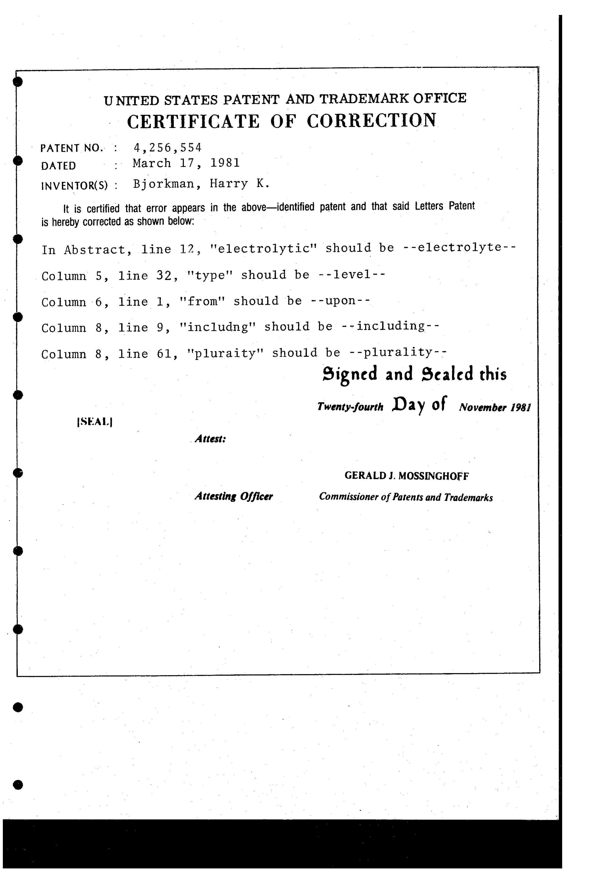
UNITED STATES PATENT AND TRADEMARK OFFICE
CERTIFICATE OF CORRECTION
INVENTOR(S) : Bjorkman, Harry K.
it is Certified that error appears in the above-identified patent and that said Letters Patent is hereby Corrected as shown below:
In Abstract, line 12, "electrolytic" should be --electrolyte-- Column 5, 1ine 32, "type' should be - -level- - Column line 1, "from" should be - - upon - - Column line 9, "including" should be -- including-- Column line 61, "plurality' should be -- plurality-- signed and Sealed this
Twenty-fourth Day of November 1981
SEAL
GERALDJ. MOSSINGHOFF
Attesting Officer Commissioner of Patents and Trademarks
Provenance
- Collection
- Cited prior art
- Original PDF
- patentimages.storage.googleapis.com →
- Filed
- 1980-03-28
- Pages
- 9
- Method
- pdftotext (the PDF's own text layer) + pdftoppm 300dpi page scans
- Source
- Google Patents bibliographic record
- Granted
- 1981-03-17
- Inventors
- Harry K. Bjorkman, Jr.; Energy Development Associates Inc
- Transcribed from
- patentimages.storage.googleapis.com →